HD-P8000 CE.qxp - Ramsey Winch
HD-P8000 CE.qxp - Ramsey Winch
HD-P8000 CE.qxp - Ramsey Winch
- No tags were found...

Create successful ePaper yourself
Turn your PDF publications into a flip-book with our unique Google optimized e-Paper software.
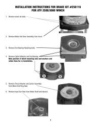
Remove seal (item #37) from gear housing end bearing (item #9). Loosen nut(item #20) and remove nylon setscrew (item #17). Remove ring gear fromgear housing end bearing, if necessary. Remove bushing (item #12) from endbearing.Press new bushing into end bearing. Install ring gear, then nylon setscrew andnut. Ring gear must be fully seated in end bearing and slot in ring gear MUSTNOT be aligned with clutch shifter hole. Install new seal in end bearing, withsharp edge of seal outward.372612 9Generously apply grease (MOBILITH SHC 007) to teeth of ring gear (item #26),20teeth of planet gears in drum (item #1), and to bushing (item #12) in gearhousing end bearing. Apply a small amount of grease to base of bushing (item#13) on motor end bearing. Apply grease to teeth of output sun gear (item #7) and input shaft (item #10).Place end of shaft with output sun gear on it into drum (item #2). Rotate shaft to engage planet gears with output sun gear.Place Gear End Bearing on Drum and engage planet gears with ring gear.Assemble motor end bearing (item #8) to drum assembly and use tie plates (items #11) and capscrews (items #15) to holdboth end bearings together. Tighten capscrews to 55 ft-lbs (75 Nm).17If necessary, remove and replace the shifter assembly (manual, item #2, or air-cylinder, item #3), as follows:MANUAL CLUTCH SHIFTER ASSEMBLYLoosen setscrew (item #19) and jam nut, then unscrew shifter assembly (item #2). Be sure slot in ring gear is not aligned withclutch shifter hole. Rotate drum, if necessary, to ensure hole and slot are not aligned.Reinstall shifter assembly with plunger, jam nut, and handle positioned in gear housing as shown below. Thread assembly (withhandle engaged in cylinder slot) into the gear housing. Pull drum toward the gear end bearing housing to remove play. Holddrum in position and continue threading the shifter assembly in until the gap between the end of the handle and cylinder is7/16 +0 -1/16 inch and handle is in the horizontal position (see below). Note: This gap will vary with drum endplay. With thedrum pulled against the motor end housing, the gap should be 3/8 inch.Lightly tighten jam nut. Rotate drum until handle snaps fully into the engaged position. Pull handle out and rotate 90°. Verify thatdrum can be rotated freely (at least one full revolution)with clutch shifter at the DISENGAGED39position. Securely tighten jam nut while holding LIGHT SWITCH454the handle. Tighten setscrew (item #19) securely.Re-check clutch operation as described on9382LIGHT ASSEMBLYpage 5.AIR CYLINDER SHIFTER ASSEMBLYLoosen set screw (item #19) to remove shifter1616assembly (item #3). To reinstall, place 1 or 219shims (items #41) over plunger and threadHANDLE (HORIZONTAL)shifter assembly into gear end housing. Add orremove shims to orient ports for pneumatic connections.Ports should point down (below horizontal).Tighten setscrew. Check for clutch oper-CYLINDERation as described on page 5.2If the light assembly (item #2) or light switch(item #45) needs to be replaced, refer to theschematic on page 12 for electrical connectionsand disassemble and reassemble as shown.419PLUNGER3JAM NUTAIR-CYLINDERCLUTCH SHIFTERMANUAL CLUTCHSHIFTERMANUAL CLUTCH ADJUSTMENT