User Instructions - English4.3 System Replacement PartsPartNo.ComponentDescriptionTRTB Top Bracket Assembly 5 ft. (1.5m) galvanized steel bracket (1-1/2” x 1-1/2” tube) includes inline shock absorber with shackle, two rung clampassemblies (each w/4-hole mounting plate for 1-1/2" tube, two 3/8"-16 x 1-5/8" x 3-1/2" U-bolts, four 3/8" lockwashers, andfour 3/8"-16 hex nut fasteners), and bottom rung clamp assembly (w/3/8"-16 x 1-5/8" x 3-1/2" U-bolt, two 3/8" lockwashers,two 3/8"-16 hex nut fasteners and two fastener caps).TRTB-7TRTB-10TRRCATRRCA-107 ft. (2m) Top BracketAssembly10 ft. (3m) Top BracketAssemblyExtra Rung Clamp Assembly(for 5 ft. top bracket)Extra Rung Clamp Assembly(for 7ft. & 10 ft. top brackets)7 ft. (2m) galvanized steel bracket (2” x 2” tube) includes inline shock absorber with shackle, two rung clamp assemblies(each w/4-hole mounting plate for 2" tube, two 3/8"-16 x 1-5/8" x 3-1/2" U-bolts, four 3/8" lockwashers, and four 3/8"-16 hextwo 3/8" lockwashers, and two 3/8"-16 hex nut fasteners).10 ft. (3m) galvanized steel bracket (2” x 2” tube) includes inline shock absorber with shackle, two rung clamp assemblies(each w/4-hole mounting plate for 2" tube, two 3/8"-16 x 1-5/8" x 3-1/2" U-bolts, four 3/8" lockwashers, and four 3/8"-16 hextwo 3/8" lockwashers, and two 3/8"-16 hex nut fasteners).Includes 4-hole mounting plate for 1-1/2" tube, two 3/8"-16 x 1-5/8" x 3-1/2" U-bolts, four 3/8" lockwashers, and four 3/8"-16 hex nut fastenersIncludes 4-hole mounting plate for 2" tube, two 3/8"-16 x 1-5/8" x 3-1/2" U-bolts, four 3/8" lockwashers, and four 3/8"-16hex nut fastenersTRLL Cable Lifeline 3/8” diameter galvanized steel cable with thimble. Various lengths available.TRQL Quick Link Galvanized steel quick-link used for connecting cable to shackle on inline shock absorber.VGCG Automatic Pass-ThroughCable Guide1.5mm locknuts.TRCG<strong>Manual</strong> Pass-ThroughCable GuideGalvanized steel cable bracket with convertible polyurethane cable retainer head includes 3/8"-16 x 1-1/4" x 2" U-Bolt, twoTRBB Bottom Bracket Assembly Galvanized steel bracket (1-1/2” x 1-1/2” tube) includes rung clamp assembly (w/4-hole mounting plate for 1-1/2" tube, two3/8"-16 x 1-5/8" x 3-1/2" U-bolts, four 3/8" lockwashers, and four 3/8"-16 hex nut fasteners), bottom rung clamp assemblyfasteners), and tensioning rod assembly (w/compression spring, two saddle clips, 7/16" washer, and six 7/16"-14 hex nutfasteners).ModelNo.VGCSTRCSCable Sleeve<strong>Vi</strong>-<strong>Go</strong> Automatic Pass-Through Cable Sleeve [Also available with carabiner (VGCS-C) or with integral swivel and carabiner (VGCS-SC)]<strong>Vi</strong>-<strong>Go</strong> <strong>Manual</strong> Pass-Through Cable Sleeve [Also available with carabiner (TRCS-C) or with integral swivel and carabiner (TRCS-SC)]5.0 System Installation (see 8.0 Inspection and Maintenance). Do not use if there are any damaged or missing parts (see 4.3 SystemReplacement Parts). resulting from a fall (see 3.0 System Requirements). may be purchasedTRIKseparately. Contact your <strong>Miller</strong> distributor.WARNING: Personal fall protection is required during installation.Persons installing the system must use caution and shall not beexposed to a fall hazard during the installation procedure. Do notconnect to any component of a partially installed system.System Installation Overview: The recommended installation procedure of the <strong>Vi</strong>-<strong>Go</strong> Vertical Cable LifelineSystem is to install from the top of the ladder down.Tools Required for Installation: Torque wrench, standard sockets--7/8" and 3/4", deep socket--9/16", standardwrenches--7/16", 11/16" and 3/4", crowfoot wrench--17mm (for part VGCG only), cable cutters--minimum 3/8"capacity needed (5/8" capacity preferred), and a tape measure.8
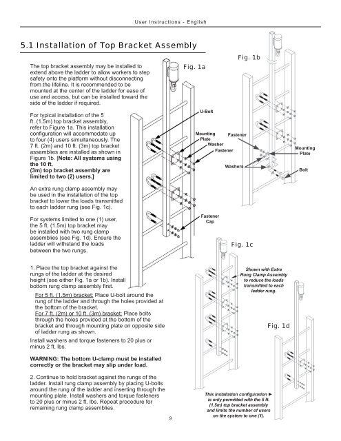
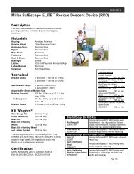
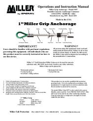
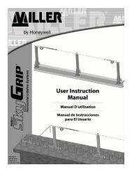
User Instructions - English5.1 Installation of Top Bracket AssemblyThe top bracket assembly may be installed toextend above the ladder to allow workers to stepsafety onto the platform without disconnectingfrom the lifeline. It is recommended to bemounted at the center of the ladder for ease ofuse and access, but can be installed toward theside of the ladder if required.For typical installation of the 5ft. (1.5m) top bracket assembly,refer to Figure 1a. This installationto four (4) users simultaneously. The7 ft. (2m) and 10 ft. (3m) top bracketassemblies are installed as shown inFigure 1b. [Note: All systems usingthe 10 ft.(3m) top bracket assembly arelimited to two (2) users.]Fig. 1aU-BoltMounting FastenerPlateWasherFastenerWashersFig. 1bMountingPlateBoltAn extra rung clamp assembly maybe used in the installation of the topbracket to lower the loads transmittedto each ladder rung (see Fig. 1c).For systems limited to one (1) user,the 5 ft. (1.5m) top bracket maybe installed with two rung clampassemblies (see Fig. 1d). Ensure theladder will withstand the loadsbetween the two rungs.FastenerCapFig. 1c1. Place the top bracket against therungs of the ladder at the desiredheight (see either Fig. 1a or 1b). InstallFor 5 ft. (1.5m) bracket: Place U-bolt around therung of the ladder and through the holes provided atthe bottom of the bracket.For 7 ft. (2m) or 10 ft. (3m) bracket: Place boltsthrough the holes provided at the bottom of thebracket and through mounting plate on opposite sideof ladder rung as shown.Install washers and torque fasteners to 20 plus orminus 2 ft. lbs.WARNING: The bottom U-clamp must be installedcorrectly or the bracket may slip under load.Shown with ExtraRung Clamp Assemblyto reduce the loadstransmitted to eachladder rung.Fig. 1d2. Continue to hold bracket against the rungs of theladder. Install rung clamp assembly by placing U-boltsaround the rung of the ladder and inserting through themounting plate. Install washers and torque fastenersto 20 plus or minus 2 ft. lbs. Repeat procedure forremaining rung clamp assemblies.9is only permitted with the 5 ft.(1.5m) top bracket assemblyand limits the number of userson the system to one (1).