MANUEL DE MONTAGE INSTALLATION MANUAL - Profurl
MANUEL DE MONTAGE INSTALLATION MANUAL - Profurl
MANUEL DE MONTAGE INSTALLATION MANUAL - Profurl

Create successful ePaper yourself
Turn your PDF publications into a flip-book with our unique Google optimized e-Paper software.
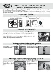
Seq 3Enfoncer un pion d’alignement (19) sur lagaine (17) coupée, du côté de la coupe, enla laissant dépasser de 11 mm.Step 3Hammer in an alignment pin (19) into thecut end (cut side) of the upper extrusion(17), leaving it protruding by 11 mm / 7/16 ”.Seq 4Enfiler l’extrémité inférieure de l’étai à travers lagaine (17) coupée, du côté de la coupe.Emboîter les 2 demi éclisses supérieures(21) sur l’extrémité coupée de la gaine (17).Step 4Slide the lower end of the stay into the upperextrusion (17) at cut end.Fit the 2 half bearings/torque links (21) into thetop (cut end) of the upper extrusion (17).Seq 5Enfiler le cordage ø 6 mm et dans la gorge dedroite (tribord) vers le bas de l’enrouleur.Vérifier la libre circulation du cordage dans lagorge.Note: la ralingue de gauche (bâbord) seraréservée à la ralingue de la voile.Emboîter la boite à réa (24) sur l’éclissesupérieure (21).Step 5Slide the 6 mm / 1/4” halyard into thestarboard (right) side groove of the extrusion(17).Check that it can run free in the groove.Note: the port (left) side groove will be usedfor the luff tape of the sail.Fit the sheave housing (24) over the twoupper half-bearings/torque links (21).www.profurl.com