MANUEL DE MONTAGE INSTALLATION MANUAL - Profurl
MANUEL DE MONTAGE INSTALLATION MANUAL - Profurl
MANUEL DE MONTAGE INSTALLATION MANUAL - Profurl
- No tags were found...

Create successful ePaper yourself
Turn your PDF publications into a flip-book with our unique Google optimized e-Paper software.
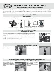
<strong>MANUEL</strong> <strong>DE</strong> <strong>MONTAGE</strong><br />
<strong>INSTALLATION</strong> <strong>MANUAL</strong><br />
Gamme Croisière Electrique<br />
Cruising Electric Systems<br />
Enrouleurs motorisés / Motorized systems<br />
N<strong>DE</strong>C 420<br />
N<strong>DE</strong>C 430<br />
N<strong>DE</strong>C 480<br />
N<strong>DE</strong>C 520<br />
N<strong>DE</strong>C 530<br />
Gamme Croisière Hydrauliques<br />
Cruising Hydraulic Systems<br />
NDHC 420<br />
NDHC 430<br />
NDHC 480<br />
NDHC 520<br />
NDHC 530<br />
Gamme Régate Electriques<br />
Racing Electric Systems<br />
N<strong>DE</strong>R 420<br />
N<strong>DE</strong>R 430<br />
N<strong>DE</strong>R 480<br />
Gamme Régate Hydrauliques<br />
Racing Hydraulic Systems<br />
NDHR 420<br />
NDHR 430<br />
NDHR 480<br />
www.profurl.com Indice A / 2008
Mécanisme d’émerillon<br />
Halyard swivel mechanism<br />
LEXIQUE<br />
GLOSSARY<br />
2 demi paliers<br />
2 half bearings<br />
Eclisse supérieure<br />
Upper bearing holder<br />
Multitop<br />
Wrapstop<br />
Tête de gaine<br />
Upper stop<br />
2 manilles lyre<br />
2 bow shackles<br />
Emerillon complet<br />
Complete Halyard<br />
swivel<br />
Vis auto-taraudeuse<br />
Self-taping screw<br />
1/2 lune<br />
C-shaped washer<br />
Avale ridoir<br />
Turnbuckle cylinder<br />
Vis de jonctions<br />
Set screws<br />
Eclisse de raccordement<br />
Joining bearing holder<br />
Vis de jonctions<br />
Set screws<br />
Vis de jonctions<br />
Set screws<br />
Eclisse de raccordement<br />
Joining bearing holder<br />
2 demi paliers<br />
2 half bearings<br />
Jonction complète<br />
Complete joining kit<br />
2 demi paliers<br />
2 half bearings<br />
Gaine intermédiaire équipée<br />
Complete intermediate extrusion<br />
Gaine intermédiaire<br />
Intermediate luff extrusion<br />
Vis de jonctions<br />
Set screws<br />
Gaine inférieure équipée<br />
Complete lower extrusion<br />
Vis avale ridoir<br />
Turnbuckle cylinder<br />
screws<br />
Gaine inférieure<br />
Lower luff extrusion<br />
Vis tétons<br />
Nippled screws<br />
Eclisse inférieure<br />
Lower bearing holder<br />
Eclisse inférieure complète<br />
Complete lower bearing holder<br />
Boitier relais<br />
Contactor unit<br />
Disjoncteur<br />
Circuit breaker<br />
Façade disjoncteur<br />
Circuit breaker<br />
plate<br />
Kit de motorisation<br />
Motorisation kit<br />
Sangle Velcro®<br />
Velcro® webbing<br />
2 demi paliers<br />
2 half bearings<br />
Manivelle<br />
Crank<br />
Handle<br />
Guide ralingue complet<br />
Complete luff rope feeder<br />
Guide ralingue<br />
Luff rope feeder<br />
Axe de dépannage<br />
pour perçeuse<br />
Square drive for<br />
drilling machine<br />
Axe d’étai<br />
Stay pin<br />
Axe de cadène<br />
Stemhead<br />
chainplate pin<br />
Vis d’arret de gaine<br />
Lower extrusion<br />
stop screws<br />
Vis de tube embase<br />
Screw for stainless<br />
steel tube<br />
Bague de fourreau<br />
Anti corrosion bushing<br />
Fourreau de tube<br />
Stainless steel ring<br />
Cardan<br />
Toggle<br />
Manchon entraineur<br />
Shape adapter<br />
Manille<br />
Shackle<br />
Bouchon<br />
de manivelle<br />
Crank<br />
socket cap<br />
Motoréducteur complet<br />
Complete gear motor<br />
Tube embase inox<br />
Stainless steel tube
TABLE <strong>DE</strong>S MATIERES / CONTENTS<br />
Préparation 4 Preparation<br />
Principe général de montage 5 Quick overview<br />
Identification du système 5 Identification of the system<br />
Identification de vos terminaisons d’étai 6 Identification of your forestay terminals<br />
Montage de la partie mécanique 7-11 Fitting the mechanical part<br />
Montage de l’option avale ridoir 12 Fitting an optional turnbuckle cylinder<br />
Mise à longueur des gaines 13 Cutting extrusions to length<br />
Montage des gaines sur l’étai 14 Fitting the extrusions onto the stay<br />
Jonction entre les gaines 15 Connecting the extrusions<br />
Montage de la gaine et de<br />
l’éclisse inférieure<br />
16 Fitting the lower extrusion and the<br />
lower bearing holder<br />
Montage de l’émerillon 16 Fitting the halyard swivel<br />
Montage du mécanisme sur les gaines 17 Fitting the mechanism onto the extrusions<br />
Montage d’un kit de motorisation 17 Fitting a motorization kit<br />
Pose du Multitop 18 Fitting the Wrapstop<br />
Installation à bord 18 Fitting on board<br />
Réglage du ridoir 19 Adjusting the turnbuckle<br />
Montage de la partie électrique (N<strong>DE</strong>) 20 Wiring of electric systems (N<strong>DE</strong> series)<br />
Montage de partie hydraulique (NDH) 21 Wiring a hydraulic system (NDH series)<br />
Montage du guide ralingue 22 Fitting the feeder<br />
Hisser la voile 22 Hoisting the sail<br />
Réglage de la hauteur de l’émerillon 23 Adjusting the position of the halyard swivel<br />
Spécifications concernant les voiles 23 Sail specifications<br />
Boîtier de commande 23 Remote control<br />
Conseils d’utilisation & 1ère utilisation 24 Operation tips & using the system for the 1st time<br />
Utilisation de la manivelle de secours 24 Using the system manually<br />
Pièces détachées 25-32 Spare parts<br />
Pièces détachées pour axe d’étai et cadène 33 Spare parts for forestay and chainplate pins<br />
Dimensions des enrouleurs PROFURL 34-35 Dimensions of PROFURL systems<br />
Dimensions boitier relais, disjoncteur et façade 36 Dimensions of contactor unit, circuit breaker and plate<br />
Dimensions des cardans 37 Dimensions of toggles<br />
Entretien 38 Maintenance<br />
Conditions de garantie 39 Limited warranty<br />
Nous contacter 40 Contact us<br />
Note aux installateurs<br />
Ce manuel devra être remis à l’utilisateur qui en prendra connaissance avant l’utilisation du matériel. Il devra être<br />
conservé à bord.<br />
Note to riggers<br />
This installation manual should be given to the boat owner, who should read it before using the system. It must be kept<br />
on board for future reference.<br />
Réception du matériel<br />
Le matériel voyage toujours aux risques et périls du destinataire. Il y a donc lieu d’effectuer une vérification dès réception<br />
et émettre toutes réserves ou exercer tous recours à l’encontre du transporteur dans les délais réglementaires.<br />
Receipt of goods<br />
All goods must be checked on delivery and the purchaser should claim from the carrier within seven days in the event<br />
of loss or damage.
Sur toutes les vues, le haut de l’étai est représenté du côté droit, et le bas du côté gauche.<br />
Every picture shows the top end of the stay on the RIGHT HAND side, and the bottom end of the stay on the LEFT<br />
HAND side.<br />
PRÉPARATION<br />
PREPARATION<br />
Les enrouleurs PROFURL ont été conçus pour être installés facilement.<br />
Pour le montage quelques outils courants sont nécessaires.<br />
Il est conseillé de démonter l’étai en totalité et de réaliser le montage sur le sol, sur une surface propre et plane.<br />
PRÉCAUTIONS PRÉLIMINAIRES:<br />
Vérifiez ou faites vérifier par une personne compétente que l’étai est en bon état. Pour information la durée de vie<br />
moyenne d’un étai est d’environ 10 ans.<br />
ATTENTION:<br />
> Sur un étai existant: AVANT de démonter l’étai, notez le réglage du ridoir (s’il existe), ou la position de l’œil inférieur<br />
de l’étai entre les lattes-ridoir.<br />
> Sur un nouvel étai: installez au préalable le nouvel étai, réglez le ridoir (si ridoir), et notez son réglage, ou la position<br />
de l’œil inférieur de l’étai entre les lattes-ridoir.<br />
The PROFURL reefing-furling systems are designed to be easily fitted.<br />
A set of common tools is required for the installation.<br />
For easier installation remove the forestay from the boat and assemble the system on a clean and level surface. Protect<br />
the system from any damage.<br />
PRELIMINARY CAUTION:<br />
Please ensure your forestay is checked by an accredited/skilled person. Recommended forestay life is about 10 years<br />
(6 years in Australia).<br />
CAUTION:<br />
Existing forestay: before attempting to remove the forestay and if a turnbuckle – or adjustment plates - are fitted, mark<br />
the position of adjustment of the turnbuckle – or adjustment plates. This will ensure the original length of the forestay<br />
is maintained.<br />
New forestay: fit the new stay to the boat first and mark the position of adjustment of the turnbuckle– or adjustment<br />
plates.
PRINCIPE GENERAL <strong>DE</strong> <strong>MONTAGE</strong><br />
QUICK OVERVIEW<br />
1. Monter provisoirement sans les gaines le kit de motorisation à la base de l’étai et/ou l’avale ridoir si cela est le cas.<br />
Ceci permettra:<br />
> de vérifier la position du mécanisme au dessus de la cadène,<br />
> de vérifier que toutes les pièces livrées avec l’enrouleur se montent correctement à la base de l’étai.<br />
2. Mesurer la distance entre le haut du kit de motorisation, ou le haut du cylindre de l’avale ridoir (si option avale ridoir),<br />
et l’extrémité du sertissage supérieur de l’étai, pour déterminer la longueur des gaines.<br />
3. Re-démonter le kit et commencer le montage de l’enrouleur proprement dit.<br />
1. Temporarily fit the motorization kit without the extrusions to the lower end of the stay and / or the turnbuckle cylinder<br />
if any. This will ensure that:<br />
> the height of the kit above the stem head chain plate suits your needs<br />
> all components delivered with your system perfectly fit to the stay lower terminal.<br />
2. Measure the distance between the top edge of the motorization kit or turnbuckle cylinder (if any) and the lower end<br />
of the top swage terminal.<br />
3. Dis-assemble the kit from the stay and start to permanently fit the system to the stay.<br />
I<strong>DE</strong>NTIFICATION DU SYSTEME<br />
SYSTEM I<strong>DE</strong>NTIFICATION<br />
Chaque enrouleur motorisé <strong>Profurl</strong> fait l’objet d’une identification. Vous<br />
trouverez sur le coté du motoréducteur le numéro de série. Sur l’émerillon le<br />
type de modèle (C420 etc...) est également spécifié.<br />
Dans le cas d’une procédure SAV, merci de relever ce numéro<br />
d’identification<br />
Seq.1<br />
Each motorized system has a serial number located on the side of the gear<br />
motor. On the swivel, the type of the model is specified (C420 etc...). In case<br />
of warranty claim, thanks to communicate this serial number.
I<strong>DE</strong>NTIFICATION <strong>DE</strong> VOS TERMINAISONS D’ÉTAI<br />
I<strong>DE</strong>NTIFICATION OF YOUR FORESTAY TERMINALS<br />
TERMINAISON SUPERIEURE <strong>DE</strong> L’ETAI<br />
FORESTAY UPPER TERMINAL<br />
Certaines terminaisons supérieures d’étai ne sont pas adaptées à la pose d’un enrouleur, et imposent une modification<br />
de l’étai:<br />
> Terminaisons à boule (principalement mâts Isomat et Z-Spars). Solution: placer une terminaison boule-œil dans la<br />
tête de mât (réf ACMO réf EBO ou équivalent), raccourcir le câble d’étai en tenant compte de la longueur de la nouvelle<br />
pièce, et sertir sur le câble une terminaison à chape articulée.<br />
> Terminaisons à T. Solution: modifier l’ancrage de l’étai sur le mât pour pouvoir disposer d’un câble comportant une<br />
chape articulée.<br />
Some terminals require special attention when assembling a reefing system:<br />
> Ball terminals (mainly found on Isomat and Z-Spars masts). Solution is to fit a ball-eye terminal (Ref: stemball eye<br />
639 from Norseman-Gibb or similar) into the mast head, to shorten the wire by a few inches, and to have a new swage<br />
terminal pressed onto the wire.<br />
> T terminals (mainly found on Kemp / Selden masts with fractional rig). Solution is to fit a new stay attachment onto the<br />
mast, and have a toggle swage terminal pressed onto the wire.<br />
TERMINAISON INFERIEURE <strong>DE</strong> L’ETAI<br />
FORESTAY LOWER TERMINAL<br />
En fonction :<br />
> de vos terminaisons d’étai,<br />
> du type d’installation choisi :<br />
- motoréducteur près du pont avec le tube d’embase recoupé<br />
ou<br />
- motoréducteur surélevé avec le tube d’embase à la longueur maxi.<br />
vous devrez:<br />
> vérifier que votre étai corresponde aux spécifications requises.<br />
> suivre les séq. page 10 et 11 pour raccorder la partie basse de l’enrouleur sur la terminaison inférieure de l’étai.<br />
According to :<br />
> the type of forestay terminals<br />
> the type of installation selected:<br />
- gear motor low to the deck with the shortened stainless steel tube<br />
- gear motor raised from deck with the stainless steel tube(length maxi),<br />
you should :<br />
> check that your forestay matches the required specifications.<br />
> follow seq. page 10 and 11 to connect the drum mechanism onto the lower end of the forestay.
<strong>MONTAGE</strong> <strong>DE</strong> LA PARTIE MECANIQUE<br />
FITTING THE MECHANICAL PART<br />
Les enrouleurs PROFURL motorisés sont montés sur l’étai comme les enrouleurs manuels en ce qui concerne:<br />
- les gaines et leurs jonctions. Voir pages 14 à 16,<br />
- l’émerillon (pages 16 et 23) et le Multitop (page 18).<br />
Le moto-réducteur est monté en lieu et place du mécanisme de tambour des enrouleurs manuels.<br />
The PROFURL motorized headsail reefing-furling systems are designed to be fitted over the existing forestay.<br />
The following components are identical to a PROFURL manual system:<br />
- extrusions and connectors. The gear motor replaces the drum mechanism found on a manual PROFURL<br />
system. See pages 14 to 16.<br />
- halyard swivel (pages 16 and 23) and Wrapstop (page 18)<br />
ADAPTATION <strong>DE</strong> L’ETAI D’ORIGINE<br />
ADAPTATION TO THE ORIGINAL FORESTAY<br />
Le cardan (voir page 2) fourni avec l’enrouleur motorisé doit être monté directement entre la terminaison<br />
inférieure de l’étai (œil) et la cadène, sans interposition d’une pièce quelconque.<br />
The toggle (please see page 2) supplied must be attached directly onto the stemhead chainplate and to<br />
the bottom eye of the forestay. No other fitting should be inserted between the toggle and the chainplate.<br />
Mesurer précisément la longueur de l’étai, d’axe en axe, et le noter.<br />
• Si l’étai comporte des lattes et un œil, veuillez repérer la position de l’œil entre les lattes<br />
• Si l’étai comporte un ridoir, veuillez repérer le réglage du ridoir pour obtenir la quête de mât et la<br />
tension d’étai requises.<br />
Accurately measure the overall length pin to pin of your forestay.<br />
• If an eye and adjustment plates are fitted please mark the position of the eye between the plates.<br />
• If a turnbuckle is fitted, please mark the adjustment position of the turnbuckle : this will maintain your existing mast<br />
rake and forestay tension.<br />
ETAI D’ORIGINE A OEIL ET LATTES<br />
ORIGINAL FORESTAY WITH EYE AND AJUSTMENT PLATES<br />
ADAPTATION <strong>DE</strong> L’ETAI<br />
a) Supprimer impérativement les lattes<br />
b) Remplacer les lattes par le cardan fourni<br />
• Si l’étai est trop court : placer les lattes recoupées en tête de mât, ou changer l’étai.<br />
• Si l’étai est trop long, le raccourcir.<br />
Seq.2<br />
ADAPTATION OF THE FORESTAY<br />
a) The adjustment plates should be completely removed<br />
b) The toggle supplied with the system should replace the adjustment<br />
• Should the forestay be too short: fit the adjustment plates or a<br />
standard toggle at the top of the stay, or fit a new forestay.<br />
• Should the forestay be too long it should be shortened to the<br />
correct length and a new eye swaged at the bottom of the stay.
ETAI D’ORIGINE AVEC RIDOIR<br />
ORIGINAL FORESTAY WITH TURNBUCKLE<br />
ADAPTATION <strong>DE</strong> L’ETAI<br />
Vous devrez disposer d’un ridoir dont la partie inférieure est une<br />
terminaison inférieure à œil. Si ce n’est pas le cas changez ou modifiez<br />
le ridoir pour obtenir une telle configuration.<br />
Montez le cardan PROFURL fourni directement entre l’œil inférieur du<br />
ridoir et la cadène avec l’axe fourni, sans interposition d’une quelconque<br />
autre pièce.<br />
Vérifiez sur le ridoir réglé que les valeurs de longueur H et de diamètre<br />
T soient inférieures aux valeurs indiquée dans le tableau 1 ci dessous.<br />
Seq.3<br />
• Dans le cas ou l’étai est trop court, ajoutez une chape en haut de<br />
l’étai ou changez l’étai.<br />
• Dans le cas ou l’étai est trop long, réduisez la longueur du câble<br />
et rajoutez à l’extrémité basse de l’étai un nouveau ridoir avec une<br />
terminaison à oeil serti.<br />
MODIFICATION OF THE FORESTAY<br />
You should check, modify or change your forestay to have an eye at the<br />
bottom of your turnbuckle.<br />
Fit the PROFURL toggle supplied between the bottom eye of the<br />
forestay and the toggle, fit the pin supplied, without using any other<br />
part in this assembly.<br />
Check on your turnbuckle that dimensions H and diameter T are smaller<br />
than the ones shown on headboard 1 below.<br />
• Should the forestay be too short : add a toggle at the top of the stay,<br />
or change for a new stay.<br />
• Should the forestay be too long : shorten the wire and have a new<br />
turnbuckle with an eye terminal swaged at the bottom end of the stay.<br />
Seq.4<br />
Tableau / headboard 1<br />
Modèles / Models<br />
T max<br />
sans avale-ridoir /<br />
without turnbuckle cylinder<br />
H max<br />
avec avale-ridoir /<br />
with turnbuckle cylinder<br />
N<strong>DE</strong>/NDH 420-430 40 mm / 1’ 37/64’’ 400 mm / 1 3’ 3/4’’ 765 mm / 2 6’ 1/8’’<br />
N<strong>DE</strong>/NDH 480-520-530 50 mm / 1’ 31/32’’ - 730 mm / 2 4’ 47/64’’<br />
ETAI D’ORIGINE A CHAPE<br />
ORIGINAL FORESTAY WITH AN EYE JAW TOGGLE<br />
ADAPTATION <strong>DE</strong> L’ETAI<br />
Enlever la chape d’origine et fixer la terminaison à oeil directement<br />
sur le cardan fourni<br />
ADAPTATION OF THE STAY<br />
You should remove the captive pin to have an eye terminal. The<br />
PROFURL toggle supplied should be fitted between the eye and the<br />
chainplate, with no other fitting inserted in between.<br />
Seq.5<br />
<strong>MONTAGE</strong> SUR UN ETAI ROD:<br />
FITTING ON A ROD STAY:<br />
Comme pour les étais en câble acier, vous devez disposer<br />
d’une terminaison à oeil qui devra être fixée directement sur<br />
le cardan fourni.<br />
As for an installation on a standard stay (wire), you must<br />
have an eye terminal which will be fitted directly on the<br />
toggle supplied.
REGLAGE <strong>DE</strong> LA HAUTEUR DU MOTOREDUCTEUR AU-<strong>DE</strong>SSUS DU PONT<br />
ADJUSTMENT OF THE HEIGHT OF THE GEAR MOTOR ABOVE <strong>DE</strong>CK<br />
1. Les enrouleurs PROFURL motorisés de la série N<strong>DE</strong>/<br />
NDH peuvent être: soit montés à la hauteur standard en<br />
utilisant le tube d’embase inox (cf page 2) tel que livré ou<br />
en raccourcissant ce tube (si nécessaire), il est possible de<br />
diminuer la hauteur du moto-réducteur au-dessus du pont,<br />
dans la limite de la longueur de la terminaison inférieure<br />
d’étai. Voir tableau 1 page 8<br />
2. Mesurer les dimensions de la terminaison d’étai selon<br />
le tableau 1 pour vérifier si le réglage est possible, et dans<br />
quelles limites le cas échéant. Voir dessins ci-dessous<br />
pour L mini<br />
3. Raccourcir le tube d’embase inox à son extrémité<br />
supérieure. Cette opération sera, de préférence, effectuée<br />
par tronçonnage sur un tour pour une finition optimale.<br />
4. Percer les trous de fixation à :<br />
1. The N<strong>DE</strong> / NDH motorized PROFURL systems allow<br />
you to choose the height of the gear motor above deck.<br />
The maximum allowed dimensions of the lower terminal<br />
may also determine the minimum height of the gear<br />
motor above deck. Please refer to headboard 1 (page<br />
8) for dimensions.<br />
2. Measure the forestay terminal as per headboard 1 to<br />
check whether adjustment is possible, and until which<br />
amount. Please refer to drawing for minimum allowed<br />
length (L) of the tube.<br />
3. Fitting the gear motor low to deck is achieved by<br />
shortening the stainless steel tube. The tube should be<br />
shortened only at the top end. It is preferable the tube is<br />
shortened by machining in a lathe.<br />
4. Having shortened the tube drill<br />
Seq.6<br />
Modèles 420 - 430 / 420 - 430 models<br />
Seq.7 Modèles 480 - 520 - 530 / 480 - 520 - 530 models<br />
5. Il conviendra enfin de procéder à une décontamination<br />
chimique, et à un polissage manuel pour<br />
éviter toute amorce de corrosion ultérieure.<br />
Monter provisoirement le moto-réducteur à la base de<br />
l’étai, ce qui permettra :<br />
• de vérifier la compatibilité des différents composants<br />
(étai, cardan, ridoir, diamètre des axes, hauteur du motoréducteur,<br />
etc..).<br />
• de simuler le passage de l’ancre sans dommage pour le<br />
moto-réducteur.<br />
• d’obtenir précisément la cote permettant de définir la<br />
longueur des gaines (voir page 13).<br />
5. If the tube has been shortened it is strongly recommended<br />
that it is electro and hand polished.<br />
This will reduce discoloration and corrosion of the tube.<br />
The gear motor should be temporarily fitted at the bottom<br />
end of the stay. This will allow you to :<br />
• check that dimensions of the different components (stay,<br />
toggle, chainplate, turnbuckle, clevis pins, etc…) match<br />
together<br />
• check that raising or lowering the anchor will not damage<br />
the system.<br />
• accurately calculate the length of extrusions (please refer<br />
to page 13).
<strong>MONTAGE</strong> <strong>DE</strong> LA FIXATION DU MOTOREDUCTEUR:<br />
STANDARD FITTING OF THE GEAR MOTOR:<br />
Seq.8<br />
<br />
<br />
<br />
<br />
<br />
10
<strong>MONTAGE</strong> DU MOTOREDUCTEUR SUR LE BATEAU<br />
FITTING THE GEAR MOTOR ON THE BOAT<br />
Seq.9<br />
Seq.10<br />
<br />
<br />
<br />
<br />
<br />
Seq.11<br />
<br />
<br />
<br />
<br />
11
<strong>MONTAGE</strong> <strong>DE</strong> L’OPTION AVALE RIDOIR (N<strong>DE</strong>/NDH 420/C430)<br />
FITTING AN OPTIONAL TURNBUCKLE CYLIN<strong>DE</strong>R<br />
(N<strong>DE</strong>/NDH420/C430)<br />
Seq.12<br />
Démonter les vis et retirer le manchon<br />
entraineur.<br />
Remove the screws and the shape<br />
adapter.<br />
Seq.13<br />
Monter l’avale ridoir dans le<br />
motoréducteur<br />
Fit the turnbuckle cylinder into the gear<br />
motor.<br />
Seq.14<br />
Monter les vis à simple téton<br />
Fit the nippled screws.<br />
Seq.15<br />
Placer le manchon entraineur en haut<br />
de l’avale ridoir.<br />
Fit the shape adapter to the top of the<br />
turnbuckle cylinder.<br />
Seq.16<br />
Monter les vis d’arrêt de gaine en haut<br />
de l’avale ridoir.<br />
Fit the stop screws to the top of the<br />
turnbuckle cylinder.<br />
Vérifier que l’intérieur du cylindre est parfaitement propre (pas de sable, poussière etc...).<br />
Please check that the inside of the cylinder is perfectly clean (no sand, no dust etc).<br />
12
MISE A LONGUEUR <strong>DE</strong>S GAINES<br />
CUTTING EXTRUSIONS TO LENGTH<br />
Monter le motoréducteur comme indiqué lors des étapes précédentes<br />
Mesurer «L» comme indiqué c’est à dire de la surface supérieure du manchon<br />
au bas du sertissage supérieur. La longueur totale des gaines sera “G ”:<br />
Fit the gear motor onto the stay as shown previously. Measure L as shown<br />
on the drawing: from the upper part of the shape adapter to the lower part of<br />
the top terminal of the stay. The total length of extrusions will be “G ”:<br />
Sans avale ridoir<br />
Without turnbuckle cylinder<br />
Avec avale ridoir<br />
With turnbuckle cylinder<br />
Seq.17<br />
Modèle / Model L Ajouter /<br />
Add<br />
= G<br />
N<strong>DE</strong> / NDH 420 - 430<br />
+ 32 mm<br />
N<strong>DE</strong> / NDH 480 - 520 - 530<br />
+ 45 mm<br />
Toutes les gaines mesurent 2 mètres. Couper l’une des gaines (sauf la gaine<br />
inférieure qui comporte l’engoujure de ralingue) avec une scie à métaux<br />
pour obtenir une longueur totale de gaines égale à “G ”.<br />
Each extrusion is 2 meters long. One of the extrusion (except the lower<br />
feeder extrusion with the opening in the groove) will be cut with a metal saw<br />
to obtain a total length as “G ”.<br />
Tracer «G».<br />
Mark «G».<br />
Seq.18 Seq.19 Seq.20<br />
Couper selon «G».<br />
Cut according to «G».<br />
Ebavurer la coupe.<br />
Trim smooth.<br />
REDÉMONTEZ LE MOTOREDUCTEUR<br />
DISASSEMBLE THE GEAR MOTOR<br />
13
<strong>MONTAGE</strong> <strong>DE</strong>S GAINES SUR L’ETAI<br />
FITTING THE EXTRUSIONS ONTO THE STAY<br />
MISE EN PLACE <strong>DE</strong> L’ÉCLISSE SUPÉRIEURE<br />
FITTING THE UPPER BEARING HOL<strong>DE</strong>R<br />
L’éclisse supérieure est identifiable par la rainure proche de son extrémité.<br />
The upper bearing holder is one piece with a slot located close to its upper end.<br />
Prendre l’éclisse supérieure.<br />
Take the upper bearing holder.<br />
Seq.21<br />
Seq.22<br />
Monter le 1/2 palier dans l’éclisse.<br />
Fit one 1/2 bearing into the bearing<br />
holder.<br />
Seq.23<br />
Placer le câble dans cet ensemble.<br />
Fit the wire into this assembly.<br />
Glisser le 2ème demi palier dans<br />
l’éclisse.<br />
Slide the 2nd 1/2 bearing into the<br />
bearing holder.<br />
Seq.24<br />
Tourner le palier de 1/4 tour.<br />
Turn the bearing by a1/4 turn.<br />
Seq.25<br />
Seq.26<br />
Enfiler le câble dans la gaine coupée.<br />
Slide the top extrusion up the forestay.<br />
Pousser l’éclisse supérieure dans la<br />
gaine jusqu’à la rainure.<br />
Push the upper bearing holder into the<br />
extrusion up to the slot.<br />
14<br />
Seq.27<br />
Seq.28<br />
Engager la demi-lune latéralement<br />
dans la rainure.<br />
Fit the stop washer into the slot in the<br />
bearing holder.<br />
Seq.29<br />
Engager la vis de butée dans la gorge<br />
de ralingue et serrer la vis de butée.<br />
Fit the stop screw into the luff groove<br />
and tighten the top screw.
JONCTIONS ENTRE LES GAINES<br />
CONNECTING THE EXTRUSIONS<br />
Seq.30<br />
Monter un palier et l’éclisse de<br />
raccordement sur le câble et répéter les<br />
séquences 24 et 25 (cf page 14).<br />
Fit a bearing and the bearing holder<br />
into the stay and repeat the seq 24 and<br />
25 (see page 14).<br />
Seq.31<br />
Engager l’éclisse dans la gaine jusqu’à<br />
la butée.<br />
Slide the bearing holder into the<br />
extrusion until it stops.<br />
Seq.32<br />
Assembler avec une gaine suivante.<br />
Fit with next extrusion.<br />
Seq.33<br />
Seq.34<br />
Seq 35<br />
Appliquer la colle fournie à l’entrée des<br />
taraudages.<br />
Dispense the adhesive sealant supplied<br />
at the threaded hole.<br />
Monter les vis de jonctions et serrer entre 4 et 5 N.m.<br />
(5 N.m = couple maxi pour éviter d’endommager la vis)<br />
Fit the set screws and tighten them between 35 and 44 lbf.in.<br />
(44 lbf.in max torque to avoid any damages on screw)<br />
PRÉCAUTIONS PARTICULIÈRES LORS DU <strong>MONTAGE</strong> <strong>DE</strong>S GAINES:<br />
• Pour un assemblage optimal et eviter toutes détériorations, disposer les gaines sur une surface plane et propre.<br />
• Vérifier que les taraudages soient propres et secs.<br />
• Ne pas resserrer les vis une fois l’installation terminée.<br />
ATTENTION: la colle frein-filet fournie nécessite des précautions d’usage: lire en page 34<br />
PRECAUTIONS TO TAKE WHEN CONNECTING THE EXTRUSIONS<br />
• For optimum assembly and to avoid damages, align luff extrusions on a flat, clean surface.<br />
• Check that all extrusions threads are clean and dry.<br />
• Do not further tighten the screws once fitting on the boat has been is completed.<br />
CAUTION: the threadlocker requires specific use conditions: see page 34<br />
15
<strong>MONTAGE</strong> <strong>DE</strong> LA GAINE ET <strong>DE</strong> L’ECLISSE INFERIEURE<br />
FITTING THE LOWER EXTRUSIONS AND THE<br />
LOWER BEARING HOL<strong>DE</strong>R<br />
Seq.36<br />
Engager un 1/2 palier et une 1/2 éclisse inférieure dans<br />
l’extrémité de la gaine inférieure et poussez jusqu’en<br />
butée.<br />
Fit the 1/2 bearing and 1/2 lower bearing holder into the<br />
end of the lower and slide inside until it stops.<br />
Seq.37<br />
Pousser le câble de coté et engager le 2ème demi palier<br />
et la 2ème éclisse.<br />
Position the forestay wire in the 1/2 bearing and fit the<br />
second 1/2 bearing and 1/2 bearing holder.<br />
Seq.38<br />
Appliquer la colle fournie à l’entrée des<br />
taraudages.<br />
Dispense the adhesive sealant supplied<br />
at the tapping entrance.<br />
Seq.39<br />
Monter les 2 vis téton pour immobilliser<br />
l’éclisse.<br />
Fit both nippled screws to hold the<br />
bearing holder.<br />
<strong>MONTAGE</strong> <strong>DE</strong> L’EMERILLON<br />
FITTING THE HALYARD SWIVEL<br />
Seq.40<br />
Enfiler l’émerillon sur les gaines dans le<br />
sens indiqué.<br />
Fit the halyard swivel onto the extrusion<br />
as shown.<br />
Seq.41<br />
Monter les 2 manilles fournies.<br />
Fit the 2 shackles onto the halyard<br />
swivel.<br />
16
<strong>MONTAGE</strong> DU MECANISME SUR LES GAINES<br />
FITTING THE MECHANISM ONTO THE EXTRUSIONS<br />
ATTENTION: Vérifiez que l’intérieur du cylindre est parfaitement propre (pas de sable, poussière, etc...).<br />
CAUTION: Please check that the inside of the cylinder is perfectly clean (no sand, dust, etc...).<br />
Seq.42<br />
Monter le motoréducteur sur la gaine inférieure.<br />
Fit the gear motor onto the lower extrusion.<br />
Seq.43<br />
Les trous T1, T2, T3 doivent être alignés avec les trous<br />
correspondants dans la gaine.<br />
Holes T1, T2, T3 must be on line with the corresponding holes in<br />
the lower extrusion.<br />
Seq.44<br />
Commencer à visser T3 en s’assurant que T1 et T2<br />
soient alignés.<br />
Fit and tighten T3 and make sure that T1 and T2<br />
remain on line with the corresponding hole.<br />
Vis d’arrêt de gaine<br />
Lower extrusion stop screws<br />
Seq.45<br />
<strong>MONTAGE</strong> D’UN KIT <strong>DE</strong> MOTORISATION SUR ENROULEUR EXISTANT<br />
FITTING A MOTORISATION KIT ON AN EXISTING FURLING SYSTEM<br />
Seq.46<br />
<br />
Perçage / drilling:<br />
Ø 8,2 mm - 21/64’’<br />
Pour convertir un enrouleur manuel ou changer de motorisation, se reporter<br />
à la notice d’installation pour le démontage.<br />
Dans le cas d’un montage de kit de motorisation sur un ancien enrouleur<br />
utilisant des gaines de 520, il peut être nécessaire sur certaines versions<br />
de repercer la gaine inférieure pour effectuer le montage. Pour cela,<br />
insérer la gaine dans le manchon et monter la vis supérieure (1). Dans le<br />
cas, ou les 2 trous inférieurs du manchon ne coïncident pas avec ceux de<br />
la gaine, utiliser le canon de perçage fourni pour repercer la gaine (Ø 8,2<br />
mm).<br />
To convert a manual furling system or to change the motorisation, please<br />
see the installation manual for dismantling.<br />
When fitting a motorisation kit on an existing system using 520 extrusions,<br />
it might be necessary on some versions to drill the lower extrusion to fit<br />
the system. In that case, slide the lower extrusion into the shape adapter<br />
and screw the upper screw (1). If the two lower holes are not aligned with<br />
the holes of the extrusion, use the drilling guide delivered to drill the extrusion<br />
(Ø 8,2 mm - 21/64’’).<br />
17
POSE DU MULTITOP<br />
FITTING THE WRAPSTOP<br />
Seq.47<br />
Mesurer précisement le diamètre Ø de<br />
l’étai.<br />
Accurately measure the stay wire<br />
diameter Ø.<br />
Seq.48<br />
Percer le Multitop à Ø -1 mm.<br />
Drill the Wrapstop at Ø minus 1 mm<br />
(3/64’’).<br />
Seq.49<br />
Monter et serrer le Multitop sous<br />
le sertissage.<br />
Fit and tighten the Wrapstop onto the<br />
wire against the swage terminal.<br />
Le Multitop sera orienté sur l’étai pour obtenir cette disposition :<br />
The large diameter of the Wrapstop should face forward:<br />
Seq.50<br />
<strong>INSTALLATION</strong> A BORD<br />
FITTING ON BOARD<br />
N’installez pas par fort vent.<br />
Do not attempt to hoist the assembled system in strong winds.<br />
Seq.51<br />
Veuiller à ne pas cambrer exagérément les gaines lors des<br />
manipulations.<br />
Make sure not to over bend extrusions when installing on board. please<br />
ensure that the grub screws have not loosened in transit / installation.<br />
Avant de capeler la terminaison supérieure d’étai sur la tête de mât,<br />
vérifier que le Multitop est correctement orienté tel que décrit en séq.61.<br />
Before re-attaching the top of the stay onto the mast head, please double check<br />
that the Wrapstop is properly aligned as per seq.61 i.e. the large diameter facing<br />
forward.<br />
18
REGLAGE DU RIDOIR<br />
TURNBUCKLE ADJUSTMENT<br />
Pour régler le ridoir, il est nécessaire de soulever le motoréducteur et de le faire coulisser sur les gaines pour dégager<br />
le ridoir. Dévisser les vis de l’avale ridoir pour faire coulisser le motoréducteur. Attention: il est nécessaire d’assurer le<br />
train de gaines pour éviter qu’il ne retombe sur le ridoir avec un noeud de bosse<br />
Régler le ridoir et l’assurer avec les moyens appropriés. Redescendre le motoréducteur, et ré-assembler en sens<br />
inverse (voir page 11)<br />
Pour les modèles électriques: il est important de prévoir une longueur de câble suffisante lors du montage afin de<br />
pouvoir soulever le motoréducteur et d’accèder au ridoir.<br />
To adjust the turnbuckle, it is necessary to lift the gear motor upwards to slide it onto the extrusions until the upper part<br />
of the turnbuckle can be reached. Unscrew the screws of the turnbuckle cylinder to slide the gear motor (1). Warning: it<br />
is mandatory to secure the whole extrusions to avoid them falling onto the turnbuckle.<br />
Adjust the turnbuckle and secure it. Slide the gear motor down and reassemble in reverse order (see page 11).<br />
For electric models: please make sure that the length of the cable is long enough to allow to lift the gear motor and to<br />
get access to the turnbuckle.<br />
<br />
<br />
<br />
<br />
Seq.52<br />
19
<strong>MONTAGE</strong> <strong>DE</strong> LA PARTIE ELECTRIQUE (N<strong>DE</strong>)<br />
WIRING OF ELECTRIC SYSTEMS (N<strong>DE</strong> series)<br />
Modèles / Models<br />
Puissance du moteur /<br />
Power of motor<br />
Ø extérieur des câbles<br />
électriques fournies: 12 & 24V<br />
Outside Ø of the<br />
electrical wires (supplied): 12 & 24V<br />
Vitesse de rotation maxi<br />
Max rotation speed<br />
Section des câbles<br />
d’alimentation fourni<br />
Minimal power supply<br />
wires section supplied<br />
Ampérage disjoncteur<br />
Circuit breaker<br />
amperage<br />
12V 24V 12V & 24V 12V & 24V 12V & 24V 12V 24V<br />
N<strong>DE</strong> 420 - 430 700 W 800 W 8 mm (5/16’’) 30 tours / min - 30 Rpm 16 mm² / sq mm 60A 50A<br />
N<strong>DE</strong> 480 - 520 - 530 700 W 800 W 8 mm (5/16’’) 30 tours / min - 30 Rpm 16 mm² / sq mm 60A 50A<br />
Câblage de l’enrouleur:<br />
Les 2 câbles électriques livrés montés sur le moto-réducteur sont pré-cablés<br />
en usine sur le moteur (long: 5 m). Ils doivent être reliés au boîtier relais qui<br />
permettra l’inversion des polarités sur le moteur électrique.<br />
Ce boîtier relais doit être installé dans les aménagements à l’intérieur du bateau,<br />
ou dans un endroit parfaitement sec. Le schéma de câblage est fourni avec le<br />
boitier relais.<br />
Un boîtier de commande (non fourni) installé dans le poste de manoeuvre<br />
(généralement dans le cockpit) sera branché sur le boîtier relais pour inverser le<br />
sens de rotation de l’enrouleur.<br />
Le coupe-circuit doit être facilement accessible en cas d’urgence.<br />
Il est recommandé que l’installation électrique soit réalisée par une<br />
personne compétente dans ce domaine (electricien).<br />
Seq.53<br />
Wiring the system:<br />
The two 5 Meter / 15 Ft electrical cables supplied are pre-wired in factory on the electric drive motor. The end of the two cables must be<br />
connected onto a contactor unit . It allows the rotation of the motor to be reversed for furling/unfurling.<br />
The contactor unit should be fitted inside the boat in a dry area. The instructions are delivered with the contactor unit.<br />
A control box (not provided) should be connected by cable to the contactor unit, to allow operating the system (normally from the cockpit).<br />
The main switch must be easily accessible in case of emergency.<br />
It is recommended that the electrical installation must be installed by a professional and skilled person (electrician).<br />
Le circuit électrique devra être impérativement protégé par le disjoncteur de type hydro-magnétique parfaitement calibré,<br />
fourni par <strong>Profurl</strong>. Ce disjoncteur est de type monopolaire. Pour les bateaux à coque métallique ou dans certains cas<br />
d’utilisation (Bateaux en NUC), un disjoncteur supplémentaire identique à celui fourni par <strong>Profurl</strong> (à commander en option)<br />
<br />
doit être installé.<br />
The electrical circuit has to be protected with the special circuit breaker supplied with the system, fitted as shown on the<br />
drawing. In case the boat has a metal hull or is being used for commercial sailing in some countries, the circuit breaker<br />
should be specified as bi-polar, and ordered as an option at <strong>Profurl</strong>.<br />
ATTENTION:<br />
Le moto-réducteur a été scellé en usine, et son étanchéité vérifiée. Toute tentative d’ouverture du capot du moto-réducteur<br />
peut, en l’absence d’outillage spécifique et du suivi rigoureux de la procédure de démontage et de remontage, conduire à<br />
l’impossibilité d’obtenir ultérieurement l’étanchéité du boîtier.<br />
Tout moto-réducteur ouvert sans l’accord préalable de <strong>Profurl</strong> donne lieu à l’annulation immédiate de la garantie<br />
CAUTION:<br />
The gear motor has been watertight tested in factory. Without the special tools and knowledge procedure to open the<br />
gear motor, the unit may be permanently damaged.<br />
Any attempt to open the gear motor without prior written consent of <strong>Profurl</strong> will avoid the warranty<br />
Veillez à dégager du trajet de la chaîne d’ancre ou de toute manoeuvre les câbles électriques ou tuyaux hydrauliques apparents<br />
au dessus du pont. Il est conseillé de les sur-gainer sur la plus grande longueur possible.<br />
Please make sure the anchor chain or any other line will not chafe on the electrical wires or hydraulic hoses above deck. Extra<br />
protection over the wires running above the deck is strongly recommended in any case.<br />
20
<strong>MONTAGE</strong> <strong>DE</strong> LA PARTIE HYDRAULIQUE (NDH)<br />
WIRING OF HYDRAULIC SYSTEM (NDH series)<br />
Modèles / Models<br />
Pression d’alimentation max<br />
Max operating pressure<br />
Vitesse de rotation maxi<br />
Max rotation speed<br />
Débit d’alimentation<br />
Flow at maw speed<br />
NDH 420 - 430 100 bars / 1470 Psi 30 tours / min - 30 Rpm 15 L / min - 3.96 US Gal /min<br />
NDH 480 - 520 - 530 140 bars / 2058 Psi 30 tours / min - 30 Rpm 15 L / min - 3.96 US Gal /min<br />
Huile<br />
• suivant norme ISO 6073 HL<br />
• Viscosité 10 à 30 cst<br />
Température de fonctionnement<br />
• moins 10°C à + 75°C avec huile standard<br />
• moins 35°C à + 75°C avec huile spéciale<br />
Raccordement hydraulique<br />
• Deux tuyaux d’alimentation avec embout femelle 7/16” JIC<br />
• Pas de drain<br />
La jonction sur le moto-réducteur devra se faire<br />
impérativement avec des raccordements hydrauliques par tuyaux souples, euxmêmes<br />
reliés à des passecoques,<br />
la canalisation rigide venant se repiquer sous le pont à l’intérieur du bateau.<br />
Centrales hydrauliques<br />
Les enrouleurs sont conçus pour être connectés sur les centrales hydrauliques<br />
les plus répandues, en respectant les pressions maximales indiquées dans le<br />
tableau ci dessus. Si les centrales utilisées développent une pression supérieure<br />
à ces valeurs, un limiteur de pression taré à la valeur correspondante devra être<br />
installé en sortie de distributeur.<br />
Il est recommandé que l’installation hydraulique soit réalisée par une personne<br />
compétente dans ce domaine.<br />
Seq.54<br />
Oil<br />
• As per ISO 6073 HL<br />
• Viscosity 10 to 30 cst<br />
Maximum operation temperatures<br />
• minus 10°C to + 75°C with standard oil<br />
• minus 35°C to + 75°C with special oil<br />
Hydraulic plumbing connection<br />
- Requires two feeding hoses finished by female 7/16”JIC terminal<br />
- No drain<br />
The connection onto the hydraulic gear motor should be achieved by flexible hoses above deck, being connected on through-deck<br />
fittings, and rigid tubing inside the boat.<br />
Hydraulic power packs<br />
The <strong>Profurl</strong> systems are designed to be connected to the most common power packs. The output to feed the system should be<br />
adjusted to match the values as shown in the above headboard. Should the power pack produce higher values than above, please<br />
use a limiter on the output feeding the system<br />
It is recommended that the hydraulic installation must be installed by a professional and skilled person.<br />
ATTENTION:<br />
Le moto-réducteur a été scellé en usine, et son étanchéité vérifiée. Toute tentative d’ouverture du capot du moto-réducteur<br />
peut, en l’absence d’outillage spécifique et du suivi rigoureux de la procédure de démontage et de remontage, conduire à<br />
l’impossibilité d’obtenir ultérieurement l’étanchéité du boîtier.<br />
Tout moto-réducteur ouvert sans l’accord préalable de <strong>Profurl</strong> donne lieu à l’annulation immédiate de la garantie<br />
CAUTION:<br />
The gear motor has been watertight tested in factory. Without the special tools and knowledge procedure to open the gear<br />
motor, the unit may be permanently damaged.<br />
Any attempt to open the gear motor without prior written consent of <strong>Profurl</strong> will avoid the warranty<br />
Veillez à dégager du trajet de la chaîne d’ancre ou de toute manoeuvre les câbles éwlectriques ou tuyaux hydrauliques<br />
apparents au dessus du pont. Il est conseillé de les sur-gainer sur la plus grande longueur possible.<br />
Please make sure the anchor chain or any other line will not chafe on the electrical wires or hydraulic hoses above deck. Extra<br />
protection over the wires running above the deck is strongly recommended in any case.<br />
21
<strong>MONTAGE</strong> DU GUI<strong>DE</strong>-RALINGUE<br />
FITTING THE FEE<strong>DE</strong>R<br />
Seq.55 Seq.56 Seq.57<br />
Placer la sangle Velcro® dans la 1ère<br />
fente du guide ralingue<br />
fit the Velcro® webbing into the first<br />
slot<br />
Placer le guide ralingue sur la gaine<br />
inférieure (ouverture vers le bas) et le<br />
Velcro® autour de la gaine.<br />
Fit the feeder to the lower extrusion with<br />
opening downwards and the Velcro®<br />
around the extrusion<br />
Insérer la sangle dans le 2ème trou et<br />
bien serrer pour immobiliser le guideralingue.<br />
Fit the Velcro® into the 2nd slot and<br />
tighten the Velcro® to firmly hold the<br />
feeder in place.<br />
Conseil: lorsque la voile est hissée, démonter le guide ralingue et conserver le dans le bateau. Lors de l’affalage de<br />
la voile, le guide ralingue doit être remis en place pour éviter d’endommager la voile.<br />
Tip: once the sail is hoisted, remove the feeder and keep it in the chart table. Before dropping down the sail, reinstalle<br />
the feeder to avoid any damages on the sail<br />
HISSER LA VOILE<br />
HOISTING THE SAIL<br />
1) Accrocher la drisse sur la manille située en haut de l’émerillon.<br />
Attach the halyard onto the shackle located at the top of the halyard<br />
swivel.<br />
2) Accrocher la têtière du génois sur la manille de point de drisse située<br />
en bas de l’émerillon.<br />
Attach the head of the sail onto the shackle located at the bottom of the<br />
halyard swivel.<br />
Accrocher le point d’amure de la voile sur la manille du point d’amure.<br />
Attach the tack of the sail onto the shackle of furling system tack.<br />
Hisser la voile en tirant sur la drisse et en guidant la ralingue dans le<br />
guide ralingue ou dans l’ouverture de la gorge.<br />
Gently pull up the sail by pulling the halyard, with someone guiding the<br />
luff tape to slide into the track.<br />
Si le bateau est équipé d’un pataras, étarquer la drisse APRES avoir<br />
repris le pataras.<br />
If the boat is equiped with a backstay, tension the halyard AFTER<br />
tensioning the backstay.<br />
2<br />
1<br />
Seq.58<br />
22
REGLAGE <strong>DE</strong> LA HAUTEUR <strong>DE</strong> L’EMERILLON<br />
HALYARD SWIVEL POSITION ADJUSTMENT<br />
La position de l’émerillon est déterminée par la longueur du guindant de la voile étarquée. Vérifier que la longueur de<br />
guindant est correcte: le bord supérieur de l’émerillon devra être situé de 5 à 10 cm en dessous du sommet des gaines<br />
lorsque la voile est étarquée.<br />
The position of the halyard swivel is determined by the luff length after the halyard has been tensioned. You should then<br />
have a distance of 5 to 10 cm (2 to 4 ”) between the top edge of the halyard swivel and the top end of the extrusions.<br />
ATTENTION:<br />
La plupart des voiles s’allongent de manière permanente à l’utilisation, et le voilier devra prendre en compte cet<br />
allongement permanent lors de la détermination de la longueur du guindant.<br />
En hissant, veiller à ce que l’émerillon ne puisse en aucun cas s’engager au dessus des gaines.<br />
CAUTION:<br />
Most sails permanently stretch after being used. Sailmakers should remember this when designing the luff length.<br />
DO NOT over tension the halyard swivel or let the halyard swivel go above the top end of the luff extrusions.<br />
SPECIFICATIONS CONCERNANT LES VOILES<br />
SAILS SPECIFICATIONS<br />
Il est recommandé de réaliser le montage des points de drisse et d’amure sur des sangles.<br />
It is recommended to use webbing onto the head and the tack of the sail, to allow furling without cringles.<br />
Modèles<br />
Models<br />
Diamètre extérieur des ralingues finies<br />
Luff line diameters (finished size)<br />
N<strong>DE</strong>/NDH 420 - 430 5 mm - 13/64’’<br />
N<strong>DE</strong>/NDH 480 - 520 - 530 - 480 6 mm - 15/64’’<br />
BOITIER <strong>DE</strong> COMMAN<strong>DE</strong><br />
REMOTE CONTROL<br />
Le boîtier de commande (non fourni) pourra avoir différentes formes : manette, interrupteur, bouton.<br />
Dans tous les cas, le boîtier de commande choisi ne doit pas permettre d’engager simultanément l’enroulement et le<br />
déroulement de la voile. Les manœuvres doivent s’effectuer en exerçant une pression constante sur la manette ou sur<br />
l’interrupteur.<br />
Dans le cas d’un interrupteur dans le cockpit, il est recommandé de choisir une position qui évite un déclenchement<br />
accidentel de la manœuvre.<br />
The remote control (not supplied) might be a joystick or a switch. In any case, the remote control should make impossible<br />
to select both directions (furl/unfurl) at the same time. The operations must be operated by pressing continuously<br />
the button of the remote control.<br />
When using a switch in the cockpit, it is recommended to choose an appropriate position to avoid the system to be<br />
activated accidentally.<br />
23
CONSEILS D’UTILISATION<br />
ADVICES<br />
Lors de l’enroulement de la voile, veillez à ce que l’écoute de génois soit choquée.<br />
ATTENTION: les efforts générés par l’enrouleur étant importants, une mauvaise utilisation de l’enrouleur peut provoquer<br />
des dégats. Il est donc de la responsabilité du skipper de veiller à ce que les manoeuvres d’enroulement et de déroulement<br />
soient réalisées par un équipier expérimenté.<br />
During the furling and unfurling operations, please make sure that the genoa sheet has been released.<br />
WARNING: as the force generated by the furler is very strong, a wrong use can generate damages.Therefore the<br />
operations have to be operated by a skilled person.<br />
<br />
1ère UTILISATION: PRECAUTIONS<br />
USING THE SYSTEM FOR THE FIRST TIME<br />
Lors de la première utilisation, il est fortement recommandé de dérouler et d’enrouler la voile manuellement à l’aide de la<br />
manivelle de secours (voir ci-dessous) afin de vérifier que les réglages éffectués soient corrects (longueur de guindant,<br />
position de l’émerillon, multitop etc...).<br />
When using the sytem for the first time, it is strongly recommended to furl and unfurl the sail manually with the handle<br />
supplied to check that all adjustments (sail’s luff length, position of the halyard swivel, wrapstop) are correct. See below<br />
to know how to use the handle.<br />
UTILISATION <strong>DE</strong> LA MANIVELLE <strong>DE</strong> SECOURS<br />
USING THE SYSTEM <strong>MANUAL</strong>LY<br />
En cas de panne électrique, une manille de secours,<br />
livrée avec l’enrouleur, est prévue pour faire fonctionner<br />
l’enrouleur. Pour cela dévisser le bouchon de protection<br />
pour accèder au logement et insérer la manivelle. Remettre<br />
le bouchon en place dès que l’utilisation de la manille est<br />
terminée.<br />
Seq.59<br />
<br />
<br />
ATTENTION:<br />
• Couper le circuit d’alimentation électrique de l’enrouleur<br />
avant d’insérer la manivelle de secours dans le logement.<br />
If the electrical power supply to the systems fails, a handle<br />
supplied with the system allows to operate the system<br />
manually. This handle must be inserted into the socket<br />
located at the rear side of the gear motor. Unscrew the<br />
cap before inserting the handle into the socket. Remove<br />
the handle and replace the cap as soon as the handle is<br />
not in use.<br />
WARNING:<br />
• Disconnect the electrical power supply of the system<br />
before inserting the handle into the socket.<br />
24
Pièces détachées N<strong>DE</strong>C / NDHC 420<br />
Spare Parts N<strong>DE</strong>C / NDHC 420<br />
Seuls les références en gras et italique sont disponibles à la vente.<br />
Only the kit parts in bold and italics can be sold.<br />
P254021<br />
P035060<br />
01320<br />
02232<br />
P254033<br />
1244<br />
52172<br />
P254020<br />
02103<br />
50380<br />
02231<br />
P254034<br />
50380<br />
01320<br />
P254032<br />
50380<br />
02234<br />
02231<br />
01320<br />
P254040<br />
52056<br />
50380<br />
52075<br />
P254031<br />
52050<br />
52175<br />
05501<br />
02229<br />
52084<br />
P251005<br />
52176<br />
02050<br />
P254014<br />
1244<br />
P254039<br />
01320<br />
P50718<br />
12V - 60A: 50162<br />
50705<br />
24V - 50A: 51157<br />
50716<br />
12V: 04446<br />
24V: 04447<br />
53234<br />
N<strong>DE</strong>C 420 12v: P190V12<br />
N<strong>DE</strong>C 420 24v: P190V24<br />
NDHC 420: P196010<br />
51408<br />
P190043<br />
cf. page 33<br />
50715<br />
53110<br />
53111<br />
N<strong>DE</strong>C 420 12v: P190112<br />
N<strong>DE</strong>C 420 24v: P190124<br />
NDHC 420: P196112<br />
25
Pièces détachées N<strong>DE</strong>C / NDHC 430<br />
Spare Parts N<strong>DE</strong>C / NDHC 430<br />
Seuls les références en gras et italique sont disponibles à la vente.<br />
Only the kit parts in bold and italics can be sold.<br />
P260021<br />
P035060<br />
01321<br />
02232<br />
P260033<br />
1245<br />
52172<br />
P260020<br />
02103<br />
50380<br />
50380<br />
02231<br />
P260034<br />
01321<br />
P260032<br />
50380<br />
02234<br />
02231<br />
01321<br />
P254040<br />
50380<br />
P260031<br />
52056<br />
52075<br />
52050<br />
05501<br />
02229<br />
P251005<br />
02050<br />
P254014<br />
52175<br />
52084<br />
52176<br />
1244<br />
P260039<br />
01321<br />
P50718<br />
12V - 60A: 50162<br />
50705<br />
24V - 50A: 51157<br />
50716<br />
12V: 04446<br />
24V: 04447<br />
53234<br />
N<strong>DE</strong>C 430 12v: P190V12<br />
N<strong>DE</strong>C 430 24v: P190V24<br />
NDHC 430: P196010<br />
51408<br />
P190043<br />
cf. page 33<br />
50715<br />
53110<br />
53111<br />
N<strong>DE</strong>C 430 12v: P190112<br />
N<strong>DE</strong>C 430 24v: P190124<br />
NDHC 430: P196112<br />
26
Pièces détachées N<strong>DE</strong>C NDHC 480<br />
Spare Parts N<strong>DE</strong>C NDHC 480<br />
Seuls les références en gras et italique sont disponibles à la vente.<br />
Only the kit parts in bold and italics can be sold.<br />
P265021<br />
P035060<br />
53040<br />
53029<br />
P265033<br />
1245<br />
02194<br />
P265020<br />
53039<br />
53079<br />
53079<br />
53027<br />
P265034<br />
53040<br />
53079<br />
P265032<br />
53054<br />
53027<br />
53040<br />
53079<br />
P265031<br />
53051<br />
53090<br />
53036<br />
50257<br />
53028<br />
P265005<br />
53044<br />
P265014<br />
P265039<br />
53091<br />
53040<br />
1245<br />
12V - 60A: 50162<br />
24V - 50A: 51157<br />
50991<br />
50988<br />
P50718<br />
12V: 04446<br />
24V: 04447<br />
53234<br />
51408<br />
P190043<br />
N<strong>DE</strong>C 480 12v: P299V12<br />
N<strong>DE</strong>C 480 24v: P299V24<br />
NDHC 480: P301010<br />
cf. page 33<br />
50989<br />
53120<br />
53121<br />
N<strong>DE</strong>C 480 12v: P299112<br />
N<strong>DE</strong>C 480 24v: P299124<br />
NDHC 480: P301112<br />
27
Pièces détachées N<strong>DE</strong>C NDHC 520<br />
Spare Parts N<strong>DE</strong>C NDHC 520<br />
Seuls les références en gras et italique sont disponibles à la vente.<br />
Only the kit parts in bold and italics can be sold.<br />
P268021<br />
P035060<br />
53042<br />
53035<br />
P268033<br />
1245<br />
02194<br />
P268020<br />
53039<br />
53079<br />
P268034<br />
53033<br />
53079<br />
53042<br />
P268032<br />
53079<br />
53033<br />
53056<br />
53042<br />
53079<br />
P268031<br />
50257<br />
53034<br />
53053<br />
53090<br />
P265005<br />
53044<br />
53038<br />
P268014<br />
P268039<br />
53091<br />
53042<br />
1245<br />
12V - 60A: 50162<br />
24V - 50A: 51157<br />
50991<br />
50988<br />
P50718<br />
12V: 04446<br />
24V: 04447<br />
53234<br />
51408<br />
P190043<br />
N<strong>DE</strong>C 520 12v: P293V12<br />
N<strong>DE</strong>C 520 24v: P293V24<br />
NDHC 520: P298010<br />
cf. page 33<br />
50989<br />
53120<br />
53121<br />
N<strong>DE</strong>C 520 12v: P293112<br />
N<strong>DE</strong>C 520 24v: P293124<br />
NDHC 520: P298112<br />
28
Pièces détachées N<strong>DE</strong>C NDHC 530<br />
Spare Parts N<strong>DE</strong>C NDHC 530<br />
Seuls les références en gras et italique sont disponibles à la vente.<br />
Only the kit parts in bold and italics can be sold.<br />
P269021<br />
P035060<br />
53043<br />
53035<br />
P269033<br />
11245<br />
02194<br />
P269020<br />
53039<br />
53079<br />
53079<br />
53033<br />
P269034<br />
53043<br />
P269032<br />
53079<br />
53056<br />
53033<br />
53043<br />
53079<br />
P269031<br />
53053<br />
50257<br />
53090<br />
P265005<br />
53038<br />
P268014<br />
53034<br />
53044<br />
P269039<br />
53091<br />
53043<br />
11245<br />
12V - 60A: 50162<br />
24V - 50A: 51157<br />
50991<br />
50988<br />
P50718<br />
12V: 04446<br />
24V: 04447<br />
53234<br />
51408<br />
P190043<br />
50989<br />
53120<br />
N<strong>DE</strong>C 530 12v: P293112<br />
N<strong>DE</strong>C 530 24v: P293124<br />
NDHC 530: P298112<br />
N<strong>DE</strong>C 530 12v: P293V12<br />
N<strong>DE</strong>C 530 24v: P293V24<br />
NDHC 530: P298010<br />
cf. page 33<br />
53121<br />
29
Pièces détachées N<strong>DE</strong>R - NDHR 420<br />
Spare Parts N<strong>DE</strong>R NDHR 420<br />
Seuls les références en gras et italique sont disponibles à la vente.<br />
Only the kit parts in bold and italics can be sold.<br />
P255021<br />
P035060<br />
00729<br />
02239<br />
P255033<br />
1244<br />
52172<br />
P255020<br />
02103<br />
50380<br />
02238<br />
P255034<br />
50380<br />
00729<br />
02238<br />
50380<br />
52113<br />
00729<br />
P255032<br />
P255040<br />
52028<br />
50380<br />
52078<br />
P255031<br />
52050<br />
05501<br />
P251005<br />
01970<br />
P255014<br />
52175<br />
02236<br />
52084<br />
52176<br />
1244<br />
P255039<br />
00729<br />
50705<br />
P50718<br />
12V - 60A: 50162<br />
24V - 50A: 51157<br />
50716<br />
12V: 04446<br />
24V: 04447<br />
53234<br />
N<strong>DE</strong>R 420 12v: P195V12<br />
N<strong>DE</strong>R 420 24v: P195V24<br />
NDHR 420: P197010<br />
51408<br />
P190043<br />
cf. page 33<br />
50715<br />
53110<br />
53111<br />
N<strong>DE</strong>R 420 12v: P195112<br />
N<strong>DE</strong>R 420 24v: P195124<br />
NDHR 420: P197112<br />
30
Pièces détachées N<strong>DE</strong>R - NDHR 430<br />
Spare Parts N<strong>DE</strong>R NDHR 430<br />
Seuls les références en gras et italique sont disponibles à la vente.<br />
Only the kit parts in bold and italics can be sold.<br />
P261021<br />
P035060<br />
51947<br />
51951<br />
P261033<br />
1245<br />
52172<br />
P261020<br />
02103<br />
50380<br />
50380<br />
51948<br />
P261034<br />
51947<br />
P261032<br />
50380<br />
52113<br />
51948<br />
51947<br />
P255040<br />
50380<br />
P261031<br />
52028<br />
52078<br />
52050<br />
05501<br />
P251005<br />
01970<br />
P255014<br />
02236<br />
52176<br />
52175<br />
52084<br />
1244<br />
P261039<br />
51947<br />
P50718<br />
12V - 60A: 50162<br />
50705<br />
24V - 50A: 51157<br />
50716<br />
12V: 04446<br />
24V: 04447<br />
53234<br />
N<strong>DE</strong>R 430 12v: P195V12<br />
N<strong>DE</strong>R 430 24v: P195V24<br />
NDHR 430: P197010<br />
P190043<br />
51408<br />
cf. page 33<br />
50715<br />
53110<br />
53111<br />
N<strong>DE</strong>R 430 12v: P195112<br />
N<strong>DE</strong>R 430 24v: P195124<br />
NDHR 430: P197112<br />
31
Pièces détachées N<strong>DE</strong>R - NDHR 480<br />
Spare Parts N<strong>DE</strong>R - NDHR 480<br />
Seuls les références en gras et italique sont disponibles à la vente.<br />
Only the kit parts in bold and italics can be sold.<br />
P266021<br />
P035060<br />
53041<br />
53032<br />
P266033<br />
1245<br />
02194<br />
P266020<br />
53039<br />
53079<br />
53079<br />
53030<br />
P266034<br />
53041<br />
P266032<br />
53030<br />
53079<br />
53055<br />
53041<br />
53079<br />
P266031<br />
53052<br />
50257<br />
53031<br />
53090<br />
P265005<br />
53044<br />
53037<br />
P266014<br />
P266039<br />
53091<br />
53041<br />
1245<br />
12V - 60A: 50162<br />
24V - 50A: 51157<br />
50991<br />
50988<br />
P50718<br />
12V: 04446<br />
24V: 04447<br />
53234<br />
51408<br />
P190043<br />
N<strong>DE</strong>R 480 12v: P300V12<br />
N<strong>DE</strong>R 480 24v: P300V24<br />
NDHR 480: P302010<br />
cf. page 33<br />
50989<br />
53120<br />
53121<br />
N<strong>DE</strong>R 480 12v: P300112<br />
N<strong>DE</strong>R 480 24v: P300124<br />
NDHR 480: P302112<br />
32
RÉFÉRENCES POUR LES AXES D’ÉTAI ET <strong>DE</strong> CADÈNES<br />
SPARE PARTS FOR FORESTAY AND CHAINPLATE PINS<br />
Axe d’étai / Forestay pin<br />
Axe pour cadène / Chainplate pin<br />
N<strong>DE</strong> & NDH C420, R420, C430 & R430<br />
Ø mm 12 14 16 18 19 22 25<br />
A P270500 P270501 P270502 P270503 P270504 P270505 P270506<br />
B 53150 53151 53152 53153 53154 53155 53156<br />
C 53140 53141 53142 53143 53144 53145<br />
D 53112<br />
E 03835<br />
F 51092<br />
G P270510 P270511 P270512 P270513 P270514 P270515 P270516<br />
H 53160 53161 53162 53163 53164 53165 53166<br />
I 53140 53141 53142 53143 53144 53145<br />
J 51501<br />
K 01224<br />
N<strong>DE</strong> & NDH C480, 520, 530<br />
Ø mm 16 18 19 22 25 28 32<br />
A P271500 P271501 P271502 P271503 P271504 P271505 P271506<br />
B 53210 53211 53212 53213 53214 53215 53216<br />
C 53200 53201 53202 53203 53204 53205<br />
D 53122<br />
E 02302<br />
F 00018<br />
G P271510 P271511 P271512 P271513 P271514 P271515 P271516<br />
H 53220 53221 53222 53223 53224 53225 53226<br />
I 53200 53201 53202 53203 53204 53205<br />
J 51308 53227<br />
K 00094<br />
33
Dimensions pour modèles N<strong>DE</strong> / NDH C420, R420, C430, R430, C480, R480, C520 et C530<br />
Dimensions for N<strong>DE</strong> / NDH C420, R420, C430, R430, C480, R480, C520 and C530 models<br />
C420 R420 C430 R430 C480 / R480 C520 C530<br />
Standard avec avale-ridoir<br />
with turnbuckle<br />
cylinnder<br />
Standard avec avale-ridoir<br />
with turnbuckle<br />
cylinnder<br />
Standard avec avale-ridoir<br />
with turnbuckle<br />
cylinnder<br />
Standard avec avale-ridoir<br />
with turnbuckle<br />
cylinnder<br />
Standard Standard Standard<br />
mm inch mm inch mm inch mm inch mm inch mm inch mm inch mm inch mm inch mm inch mm inch<br />
A 68 2’ 43/64’’ Voir / see standard 68 2’ 43/64’’ Voir / see standard 68 2’ 43/64’’ Voir / see standard 68 2’ 43/64’’ Voir / see standard 68 2’ 43/64'' 68 2’ 43/64'' 68 2’ 43/64''<br />
B 10 13/32’’ Voir / see standard 10 13/32’’ Voir / see standard 10 13/32’’ Voir / see standard 10 13/32’’ Voir / see standard 14 35/64'' 14 35/64'' 14 35/64''<br />
C 28 17/64’’ Voir / see standard 28 17/64’’ Voir / see standard 28 17/64’’ Voir / see standard 28 17/64’’ Voir / see standard 28 1’ 7/64'' 28 1’ 7/64'' 28 1’ 7/64''<br />
E 103 4’ 1/16’’ Voir / see standard 103 4’ 1/16’’ Voir / see standard 140 5’ 33/64’’ Voir / see standard 140 5’ 33/64’’ Voir / see standard 146 5’ 3/4'' 146 5’ 3/4'' 168 5’ 3/4''<br />
F 498 1 7’ 39/64’’ 863 2 9’ 31/32’’ 498 1 7’ 39/64’’ 863 2 9’ 31/32’’ 498 1 7’ 39/64’’ 863 2 9’ 31/32’’ 498 1 7’ 39/64’’ 863 2 9’ 31/32’’ 827 2 8’ 9/16'' 827 2 8’ 9/16'' 827 2 8’ 9/16''<br />
G 126 4’ 61/62’’ Voir / see standard 126 4’ 61/62 Voir / see standard 170 6’ 11/16’’ Voir / see standard 170 6’ 11/16’’ Voir / see standard 170,5 6’ 11/16'' 170 6’ 11/16'' 192,5 6’ 11/16''<br />
H max 400 1 3’ 3/4’’ 765 2 6’ 1/8’’ 400 1 3’ 3/4’’ 765 2 6’ 1/8’’ 400 1 3’ 3/4’’ 765 2 6’ 1/8’’ 400 1 3’ 3/4’’ 765 2 6’ 1/8’’ 730 2 4’ 47/64'' 730 2 4’ 47/64'' 730 2 4’ 47/64''<br />
I 144 5’ 43/64’’ Voir / see standard 144 5’ 43/64’’ Voir / see standard 196 7’ 3/4’’ Voir / see standard 196 7’ 3/4’’ Voir / see standard 194 7’ 41/64'' 194 7’ 41/64'' 218 7’ 41/64''<br />
J 72 2’ 53/64’’ Voir / see standard 72 2’ 53/64’’ Voir / see standard 72 2’ 53/64’’ Voir / see standard 72 2’ 53/64’’ Voir / see standard 84 3’ 5/16'' 84 3’ 5/16'' 84 3’ 5/16''<br />
K 47 1’ 27/32’’ Voir / see standard 47 1’ 27/32’’ Voir / see standard 47 1’ 27/32’’ Voir / see standard 47 1’ 27/32’’ Voir / see standard 47 1’ 27/32'' 47 1’ 27/32'' 47 1’ 27/32''<br />
L standard 491 1 7’ 21/64’’ 856 2 9’ 45/64’’ 491 1 7’ 21/64’’ 856 2 9’ 45/64’’ 491 1 7’ 21/64’’ 856 2 9’ 45/64’’ 491 1 7’ 21/64’’ 856 2 9’ 45/64’’ 845 2 9’ 17/64'' 845 2 9’ 17/64'' 845 2 9’ 17/64''<br />
L mini 419 1 4’ 1/2’’ 784 2 6’ 55/64’’ 419 1 4’ 1/2’’ 784 2 6’ 55/64’’ 419 1 4’ 1/2’’ 784 2 6’ 55/64’’ 419 1 4’ 1/2’’ 784 2 6’ 55/64’’ 690 2 3’ 11/64'' 690 2 3’ 11/64' 690 2 3’ 11/64'<br />
M 75 2’ 15/16’’ Voir / see standard 75 2’ 15/16’’ Voir / see standard 75 2’ 15/16’’ Voir / see standard 75 2’ 15/16’’ Voir / see standard 100 3’ 15/16'' 100 3’ 15/16'' 100 3’ 15/16''<br />
N 23 29/32’’ Voir / see standard 23 29/32’’ Voir / see standard 23 29/32’’ Voir / see standard 23 29/32’’ Voir / see standard 23 29/32'' 21 53/64'' 21 53/64''<br />
O standard 221 8’ 45/64’’ Voir / see standard 221 8’ 45/64’’ Voir / see standard 221 8’ 45/64’’ Voir / see standard 221 8’ 45/64’’ Voir / see standard 328 1 0’ 29/32’’ 328 1 0’ 29/32’’ 328 1 0’ 29/32’’<br />
O mini 149 5 55/64’’ Voir / see standard 149 5 55/64’’ Voir / see standard 149 5 55/64’’ Voir / see standard 149 5 55/64’’ Voir / see standard 173 6’ 13/16’’ 173 6’ 13/16’’ 173 6’ 13/16’’<br />
P standard 400 1 3’ 3/4’’ Voir / see standard 400 1 3’ 3/4’’ Voir / see standard 400 1 3’ 3/4’’ Voir / see standard 400 1 3’ 3/4’’ Voir / see standard 495 1 7’ 31/64’’ 495 1 7’ 31/64’’ 495 1 7’ 31/64’’<br />
P mini 328 1 0’ 29/32’’ Voir / see standard 328 1 0’ 29/32’’ Voir / see standard 328 1 0’ 29/32’’ Voir / see standard 328 1 0’ 29/32’’ Voir / see standard 340 1 1’ 25/64’’ 340 1 1’ 25/64’’ 340 1 1’ 25/64’’<br />
Q 310 1 0’ 13/64’’ Voir / see standard 310 1 0’ 13/64’’ Voir / see standard 310 1 0’ 13/64’’ Voir / see standard 310 1 0’ 13/64’’ Voir / see standard 315 1 0’ 13/32’’ 315 1 0’ 13/32’’ 315 1 0’ 13/32’’<br />
R1 134 5’ 9/32’’ Voir / see standard 134 5’ 9/32’’ Voir / see standard 134 5’ 9/32’’ Voir / see standard 134 5’ 9/32’’ Voir / see standard 150 5’ 29/32’’ 150 5’ 29/32’’ 150 5’ 29/32’’<br />
R2 94 3’ 45/64’’ Voir / see standard 94 3’ 45/64’’ Voir / see standard 94 3’ 45/64’’ Voir / see standard 94 3’ 45/64’’ Voir / see standard 100 3’ 15/16’’ 100 3’ 15/16’’ 100 3’ 15/16’’<br />
S1 62 2’ 7/16’’ Voir / see standard 62 2’ 7/16’’ Voir / see standard 62 2’ 7/16’’ Voir / see standard 62 2’ 7/16’’ Voir / see standard 75 2’ 61/64’ 75 2’ 61/64’ 75 2’ 61/64’<br />
S2 182 7’ 11/64’’ Voir / see standard 182 7’ 11/64’’ Voir / see standard 182 7’ 11/64’’ Voir / see standard 182 7’ 11/64’’ Voir / see standard 197 7’ 3/4’’ 197 7’ 3/4’’ 197 7’ 3/4’’<br />
T max 40 1’ 37/64’’ Voir / see standard 40 1’ 37/64’’ Voir / see standard 40 1’ 37/64’’ Voir / see standard 40 1’ 37/64’’ Voir / see standard 50 1' 31/32’’ 50 1' 31/32’’ 50 1' 31/32’’<br />
U standard 462 1 6’ 3/16’’ Voir / see standard 462 1 6’ 3/16’’ Voir / see standard 462 1 6’ 3/16’’ Voir / see standard 462 1 6’ 3/16’’ Voir / see standard 568 1 0’ 23/64’’ 568 1 0’ 23/64’’ 568 1 0’ 23/64’’<br />
U mini 390 1 3’ 23/64’’ Voir / see standard 390 1 3’ 23/64’’ Voir / see standard 390 1 3’ 23/64’’ Voir / see standard 390 1 3’ 23/64’’ Voir / see standard 413 1 4’ 17/64’’ 413 1 4’ 17/64’’ 413 1 4’ 17/64’’<br />
V 133 5’ 15/64’’ Voir / see standard 133 5’ 15/64’’ Voir / see standard 133 5’ 15/64’’ Voir / see standard 133 5’ 15/64’’ Voir / see standard 148 5’ 53/64'' 148 5’ 53/64'' 148 5’ 53/64''<br />
W 94 3’ 45/64’’ Voir / see standard 94 3’ 45/64’ Voir / see standard 94 3’ 45/64’ Voir / see standard 94 3’ 45/64’ Voir / see standard 114 4’ 31/64'' 114 4’ 31/64'' 114 4’ 31/64''<br />
X 61 2’ 13/32’’ Voir / see standard 61 2’ 13/32’’ Voir / see standard 61 2’ 13/32’’ Voir / see standard 61 2’ 13/32’’ Voir / see standard 73 2’ 7/8’’ 73 2’ 7/8’’ 73 2’ 7/8’’<br />
Y 42 1’ 21/32’’ Voir / see standard 42 1’ 21/32’’ Voir / see standard 42 1’ 21/32’’ Voir / see standard 42 1’ 21/32’’ Voir / see standard 48 1 57/64'' 52 2 3/64'' 52 2 3/64''<br />
Z standard 16485 54 1’ 1/32’’ 16850 55 3’ 25/64’’ 14485 47 6’ 9/32’’ 14850 48 8’ 41/64’’ 18485 60 7’ 3/4’’ 18850 61 10’ 1/8’’ 16485 54 1’ 1/64’ 16850 55 3’ 25/64’’ 18813 61 8’ 43/64'' 20813 68 3’ 13/32'' 22813 74 10’ 5/32''<br />
Z mini 16413 53 10’ 3/16’’ 16778 55 0’ 35/64’’ 14413 47 3’ 7/16’’ 14778 48 5’ 13/16’’ 18413 60 4’ 59/64’’ 18778 61 7’ 19/64’’ 16413 53 10’ 3/16’’ 16778 55 0’ 35/64’’ 18658 61 2’ 9/16'' 20658 67 9’ 5/16'' 22658 74 4’ 3/64’’<br />
34
Dimensions pour modèles N<strong>DE</strong> / NDH C420, R420, C430, R430, C480, R480, C520 et C530<br />
Dimensions for N<strong>DE</strong> / NDH C420, R420, C430, R430, C480, R480, C520 and C530 models<br />
N<strong>DE</strong>-NDH 420 / 430: montage standard:<br />
N<strong>DE</strong> - NDH 420 / 430: standard fitting<br />
N<strong>DE</strong>-NDH 480 / 520 / 530: montage avec avale-ridoir:<br />
N<strong>DE</strong> - NDH 480 / 520 / 530: fitting with turnbuckle cylinder<br />
35
Dimensions Pour Boitier Relais, Disjoncteur et<br />
Facade De Disjoncteur<br />
Dimensions For Contactor Unit, Circuit Breaker and<br />
Circuit Breaker Plate<br />
Version 1<br />
Boitier relais / Contactor unit<br />
Disjoncteur / Circuit breaker<br />
Version 2<br />
Boitier relais / Contactor unit Disjoncteur / Circuit breaker Façade de disjoncteur /<br />
Circuit breaker plate<br />
36
Dimensions des cardans pour les modèles 420 et 430<br />
Dimensions of the toggle for 420 and 430 models<br />
Axe étai / Forestay pin<br />
Axe cadène/ Chainplate pin<br />
Dimensions des cardans pour les modèles 480, 520 et 530<br />
Dimensions of the toggle for 480, 520 and 530 models<br />
Axe étai / Forestay pin<br />
Axe cadène/ Chainplate pin<br />
37
ENTRETIEN<br />
MAINTENANCE<br />
Votre enrouleur PROFURL a été conçu pour fonctionner sans entretien pendant de nombreuses années. Cependant pour lui conserver<br />
un aspect neuf, il est recommandé de procéder au moins une fois par an à un rinçage à l’eau claire des parties mécaniques, et à un<br />
nettoyage des gaines avec un chiffon imbibé d’alcool. Pour les parties en inox comme le tube embase, <strong>Profurl</strong> vous recommande<br />
d’utiliser un passiveur comme le Wichinox de Wichard (ref: 9601)<br />
Your PROFURL system requires no special maintenance. You can rinse it with fresh water as often as necessary to remove salt and<br />
dirt from the components. This will also improve the appearance of the system. For some parts of the motorized systems like the<br />
stainless steel tube, <strong>Profurl</strong> recommends to use Wichinox (part # 9601), a Wichard product, to passivate the stainless steel parts.<br />
ATTENTION<br />
Ne jamais appliquer de lubrifiant type WD 40 ® (ou équivalent), ce qui endommagerait irrémédiablement les joints d’étanchéité et<br />
détruirait à terme les roulements à billes.<br />
CAUTION<br />
Never use WD 40 ® (or similar) on the seals in the drum or halyard swivel mechanism as it will permanently damage them and affect<br />
the watertightness of the bearings.<br />
ATTENTION:<br />
est livré avec l’enrouleur PROFURL un mastic adhésif, se reporter aux conditions d’utilisation ci-dessous<br />
CAUTION:<br />
with the PROFURL system, an adhesive sealant is supplied. Read below the conditions of use.<br />
FR: R36/37 Irritant pour les yeux et les voies respiratoires. - S23 Ne pas respirer les vapeurs. - S25 Éviter le contact avec les yeux.<br />
S26 En cas de contact avec les yeux, laver immédiatement et abondamment avec de l’eau et consulter un spécialiste. - S36 Porter un vêtement<br />
de protection approprié. - S51 Utiliser seulement dans des zones bien ventilées.<br />
EN: R36/37 Irritating to eyes and respiratory system. - S23 Do not breathe vapour. - S25 Avoid contact with eyes. - S26 In case of contact with<br />
eyes, rinse immediately with plenty of water and seek medical advice. - S36 Wear suitable protective clothing. - S51 Use only in well-ventilated<br />
areas.<br />
<strong>DE</strong>: R36/37 Reizt die Augen und die Atmungsorgane. - S23 Dampf nicht einatmen. - S25 Berührung mit den Augen vermeiden. - S26 Bei Berührung<br />
mit den Augen sofort gründlich mit Wasser abspülen und Arzt konsultieren. - S36 Bei der Arbeit geeignete Schutzkleidung tragen.<br />
S51 Nur in gut gelüfteten Bereichen verwenden.<br />
NL: R36/37 Irriterend voor de ogen en de ademhalingswegen. - S23 Damp niet inademen. - S25 Contact met de ogen vermijden.<br />
S26 Bij aanraking met de ogen onmiddellijk met overvloedig water afspoelen en raadpleeg en arts. - S36 Draag geschikte beschermende kleding.<br />
S51 Uitsluitend op goed geventileerde plaatsen gebruiken.<br />
IT: R36/37 Irritante per gli occhi e le vie respiratorie. - S23 Non respirare i vapori. - S25 Evitare il contatto con gli occhi. - S26 In caso di contatto<br />
con gli occhi, lavare immediatamente e abbondantemente con acqua e consultare un medico. - S36 Usare indumenti protettivi adatti. - S51 Usare<br />
soltanto in luogo ben ventilato.<br />
Xi<br />
(FR) Irritant, (EN) Irritant,<br />
(<strong>DE</strong>) Reizend,<br />
(NL) Irriterend<br />
(IT) (ES) (PT) Irritante,<br />
(NO) Irriterende (SV) Irriterande<br />
(DA) Lokalirriterende<br />
(FI) Ärsyttävä<br />
ES: R36/37 Irrita los ojos y las vías respiratorias. - S23 No respirar los vapores. - S25 Evítese el contacto con los ojos. - S26 En caso de contacto<br />
con los ojos, lávense inmediata y abundantemente con agua y acúdase a un médico. - S36 Úsese indumentaria protectora adecuada. - S51<br />
Úsese únicamente en lugares bien ventilados.<br />
PT: R36/37 Irritante para os olhos e vias respiratórias. - S23 Não respirar os vapores. - S25 Evitar o contacto com os olhos. - S26 Em caso de<br />
contacto com os olhos, lavar imediata e abundantemente com água e consultar um especialista. - S36 Usar vestuário de protecção adequado.<br />
- S51 Utilizar somente em locais bem ventilados.<br />
NO: R36/37 Irriterer øynene og luftveiene. - S23 Unngå innånding av damp. - S25 Unngå kontakt med øynene. - S26 Får man stoffet i øynene,<br />
skyll straks grundig med store mengder vann og kontakt lege. - S36 Bruk egnede verneklær. - S51 Må bare anvendes på godt ventilerte steder.<br />
SV: R36/37 Irriterar ögonen och andningsorganen. - S23 Undvik inandning av ånga. - S25 Undvik kontakt med ögonen. - S26 Vid kontakt med<br />
ögonen, spola genast med mycket vatten och kontakta läkare. - S36 Använd lämpliga skyddskläder. - S51 Sörj för god ventilation.<br />
DA: R36/37 Irriterer øjnene og åndedrætsorganerne. - S23 Undgå indånding af dampe. - S25 Undgå kontakt med øjnene. - S26 Kommer stoffet i<br />
øjnene, skylles straks grundigt med vand og læge kontaktes. - S36 Brug særligt arbejdstøj. - S51 Må kun bruges på steder med god ventilation.<br />
FI: R36/37 Ärsyttää silmiä ja hengityselimiä. - S23 Vältettävä höyryn/sumun hengittämistä. - S25 Varottava kemikaalin joutumista silmiin.<br />
- S26 Roiskeet silmistä huuhdeltava välittömästi runsaalla vedellä ja mentävä lääkäriin. - S36 Käytettävä sopivaa suojavaatetusta. - S51 Huolehdittava<br />
hyvästä ilmanvaihdosta.<br />
Réf / Part #: 52225<br />
PRECAUTIONS D’UTILISATON:<br />
• Il est recommandé d’utiliser cette colle frein-filet par temps sec et lorsque la température ambiante est supérieure à 5°c. Sinon utiliser cette colle sous abri.<br />
• Les pièces à coller doivent être à la même température ou à une température supérieure à celle de l’environnement (pour éviter la condensation).<br />
• Pour une performance maximum du frein-filet, il est recommandé une polymérisation de 24h (à température supérieure à 5°c)<br />
PRECAUTIONS OF USE<br />
• When using the threadlocker, check that the ambient temperature is above 5°c and the weather is dry. If not use the threadlocker inside.<br />
• The parts must be at the same temperature or warmer than the environment (to avoid condensation and dampness).<br />
• To get the maximum performance of the threadlocker, it is recommended 24h of polymerisation (with an ambient temperature above 5°c).<br />
38
CONDITIONS <strong>DE</strong> GARANTIE<br />
Sans préjudice de la garantie légale, votre enrouleur PROFURL est garanti 3 (trois) ans à partir de la date de sa mise en service, la facture d’achat<br />
au revendeur ou au constructeur faisant foi.<br />
La garantie se limite au remplacement ou à la réparation en nos ateliers des pièces reconnues défectueuses.<br />
La garantie disparaît immédiatement et complètement si le client modifie ou fait réparer sans l’accord de Wichard le matériel fourni. La réparation,<br />
la modification ou le remplacement des pièces pendant la période de garantie ne peuvent avoir pour effet de prolonger le délai de garantie du<br />
matériel.<br />
La garantie ne couvre pas les dommages consécutifs à un mauvais montage, à une utilisation inappropriée ou abusive, à un accident ou à toute<br />
fortune de mer.<br />
VERIFICATIONS IMPERATIVES<br />
Il appartient à l’utilisateur de vérifier ou de faire vérifier par une personne compétente que :<br />
- la longueur du guindant de la voile est correcte, ni trop longue ni trop courte<br />
- les fixations de l’enrouleur à la base de l’étai sont correctement réalisées<br />
- les différentes vis sont correctement serrées<br />
- la drisse, une fois la voile hissée, est correctement tendue<br />
- le Multitop est correctement installé et serré<br />
- le diamètre de l’axe de fixation fourni avec l’enrouleur correspond bien à celui de l’axe d’origine<br />
- Le voltage adequat au système ou la pression d’alimentation adéquate<br />
Les ennuis consécutifs à ces défauts de montage ou d’utilisation, souvent constatés, ne sont pas couverts par la garantie.<br />
PROCEDURE A SUIVRE EN CAS D’APPEL EN GARANTIE<br />
En cas d’impossibilité de faire constater par une personne compétente la nature des dommages, le client prendra contact directement avec WICHARD<br />
S.A. - France.<br />
La ou les pièce(s) défectueuse(s) devra (devront) impérativement être retournée(s) pour inspection à WICHARD S.A.S (France), à WICHARD, Inc<br />
aux USA ou à WICHARD PACIFIC Pty Ltd, port aux frais du client, dans les 14 (quatorze) jours suivant le constat de l’avarie.<br />
En cas de réexpédition du matériel depuis un pays tiers, les frais de dédouanement éventuels correspondant à l’entrée en France ou aux USA restent<br />
à la charge du client.<br />
Au cas où le client exige une réexpédition des pièces avant réception des pièces défectueuses par WICHARD S.A.S (France), WICHARD Inc (USA)<br />
ou WICHARD PACIFIC Pty, celles-ci seront facturées et payables avant l’expédition, règlement par carte bancaire, transfert bancaire ou tout autre<br />
moyen. Si la responsabilité de WICHARD est reconnue, WICHARD remboursera le client dans les meilleurs délais.<br />
LIMITED WARRANTY<br />
Your PROFURL reefing-furling system is warranted for a period of 3 (three) year from the date of purchase against parts and materials.<br />
This warranty is limited to the repair and replacement of defective parts by an authorized PROFURL dealer and only after the written consent of<br />
WICHARD S.A.S (France), WICHARD Inc, or WICHARD PACIFIC (addresses below).<br />
The warranty is void if the system is modified or repaired prior written consent of WICHARD S.A.S (France), WICHARD Inc or WICHARD PACIFIC.<br />
This warranty covers only the WICHARD parts and materials. Any accidental damage or expenses are not covered by the warranty.<br />
This warranty does not cover damages caused by a system which was installed or used improperly, damaged by collision, or any act of God.<br />
In the event of a warranty claim, WICHARD’s liability is limited to the value of the system at the date of purchase. Packaging costs, shipment or<br />
custom charges are at customer’s expense.<br />
OWNER SHOULD CHECK OR HAVE CHECKED BY A SKILLED PERSON THE FOLLOWING<br />
After installation of the system the customer must check the following:<br />
- the sail luff is cut at the correct length<br />
- the locking devices attaching the drum mechanism are properly secured<br />
- all screws are tightened<br />
- the halyard is tight when the sail is hoisted<br />
- the Wrapstop is properly installed as shown in this manual<br />
- the diameter of the clevis pin supplied with the WICHARD’s system is correct with the forestay terminal<br />
- the appropriate power of the system or the operation pressure<br />
WHICH PROCEDURE SHOULD YOU FOLLOW IN CASE OF WARRANTY CLAIM<br />
• In case it is impossible for the owner to have the damage checked by a skilled person, the owner will contact WICHARD S.A.S (France), WI-<br />
CHARD, Inc (USA) or WICHARD PACIFIC Pty Ltd. Please see address below.<br />
• The defective part should be returned at owner’s expenses to WICHARD S.A.S (France), WICHARD Inc or WICHARD PACIFIC Pty Ltd within 14<br />
(fourteen) days after the damage occured to the system.<br />
• In case the parts are shipped from a country outside France, USA or Australia, custom duties for return to WICHARD should be prepaid by the<br />
owner.<br />
• In case the owner will demand urgent replacement of part before the defective part is received by WICHARD, the replacement part will be charged<br />
to the owner, and paid before shipping (credit cards accepted). In case WICHARD’s responsibility is finally acknowledged, WICHARD will refund the<br />
owner.<br />
• No replacement part purchased from a PROFURL dealer will be refunded to the owner.<br />
• In the normal warranty procedure, the parts will be returned to the owner, shipping and customs at owner’s expenses.<br />
39
www.profurl.com<br />
WICHARD France<br />
Hotline / Support technique / SAV<br />
33 rue de l’Etoile du matin<br />
44600 Saint Nazaire,<br />
France<br />
Tel +33 (0)2 51 76 00 35<br />
Fax +33 (0)2 40 01 40 43<br />
Email : hotline@wichard.com<br />
WICHARD, Inc<br />
148a Bryce Blvd<br />
Fairfax - VT05454<br />
USA<br />
Tel : +1 401 683 5055<br />
Fax :+1 802 655 4689<br />
Free toll number: + 1 800 852-7084<br />
Email : info@wichard-usa.com<br />
WICHARD PACIFIC Pty Ltd<br />
PO Box 712 Edgecliff NSW 2027<br />
Australia<br />
Tel : + 61 2 9516 0677<br />
Fax : + 61 2 9516 0688<br />
Freecall from Australia: 1800 639 767<br />
Email : info@wichard.com.au<br />
P30FGB08<br />
40