
You also want an ePaper? Increase the reach of your titles
YUMPU automatically turns print PDFs into web optimized ePapers that Google loves.
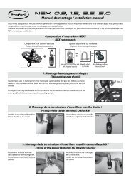
I - GENERAL DESCRIPTIONNote : names in bold refer to parts identified on the exploded viewMK 3RThe <strong>PROFURL</strong> in-boom furling system includes :1. One set of luff profiles (1 and 2) articulated on the aft face of the mast .There are 2 different kinds of luff profiles : one 0.60 m long feeder profile (1) onwhich the feeder(3) is attached, and several 2 meters long normal luff profiles (2)depending on the mainsail’s luff length. One of these 2 meters long normal luffprofiles (2) will be re-cut to length at its upper end to match the expected luglength of the boat. The different luff profiles (1 et 2) are connected to each other bymean of connectors/articulations (4), which are connected to articulationbrackets (5) attached on the aft face of the mast.CAUTION : the articulation brackets (5) have a stainless steel pin. Check thedifference with end brackets (6), which have Nylon flanges.2. Articulation brackets (5) attached to the mast with 3 slide screws (7) slipped inthe mast track. Every slide screw (7) has a thread and a flat end going through ahole of the articulation brackets (5). The thread of the slide screws (7) receives alocknut (8) for attachment.3. Connectors/articulations (4) also used to connect the different luff profiles (1 and2), held by set screws (9). The lower end of the 0.60m long feeder profile (1) willbe connected on the gooseneck articulation (10), thus allowing the luff profiles (1and 2) to rotate together with the boom.4. A sheave box (11) through which the original mainsail halyard is passing. Thesheave box (11) will be fit at the top of the luff profiles (1 and 2). It is assembled onthe end brackets [2 times (6)], themselves being attached by mean of slide screws(7) and locknuts (8).5. The gooseneck (12a) and (12b) fit on the mast with 2 slide screws (7), and 2gooseneck plates (13) cambered at the mast shape before fitting, and which will beriveted onto the mast with the conical head pop rivets (14) supplied.6. A boom profile(15) which has been delivered upon request in 5 or 6 meters. It willprobably have to be re-cut to length when fitting to match the expected boom length.7. A mandrel (16) which turns on bearings (17 and 18) fit on a bearing holder (19)at the rear end of the boom, and on the drum bearing holder (21) front, turningaround a pin inserted in each of the boom end fittings (22 and 23). When recuttingthe boom profile (15) to length, the mandrel (16) should also be re-cut.8. A drum boom end fitting (22). It includes the drum (21) fit onto the mandrel (16):the drum being loaded with the furling line supplied, by pulling on the furling line andreleasing the mainsail halyard it will rotate the mandrel, which will furl the sail.9. 1 reinforced adjustable mainsheet bail (26) and 2 adjustable mainsheet bails (25).10. A special boomvang (27). It is attached :- onto the mast by mean of a boomvang attachment, including an gooseneck (12)attached onto the mast with 2 slide screws (7) locknuts (8) and 2 gooseneck plates(13) which will be riveted on the mast with pop rivets (14) with conical head supplied.The boomvang lower end will be attached onto an articulation eye (39) rotating in theboomvang gooseneck.- onto the boom with a boomvang hound (28).11. A ball bearing block (35) to lead the furling line (51) to the cockpit.4
MK 3R5
MK 3RTOOLS NEEDED FOR FITT<strong>IN</strong>GIn all cases of fitting• A tape line• An electric drill• A set of drills• A hack saw with a (new) blade with small teeth• A file• A pencil• A plastic hammer• A 13 mm pipe-wrench• A 24 mm pipe-wrench• A dynamometrical wrench (1daN/m)• 1 set of Allen wrenches (supplied)• 2 clamps with opening 300 mm• Universal pliers• A cutter blade (with new blades)• A large sheet of paper with corners perfectly at 90° and adhesive tape• Several small plywood or rubber shims.• A pop rivet gun for 5 mm stainless steel rivets.• A ratchet tie down strap more than twice the boom length.Note : the plates to fit the gooseneck and boomvang attachment are 8 mm thick andmade out of aluminium. A convenient hydraulic or mechanical press should be used tobend them at the mast shape, fitting them on the mast with the clamps.If the fitting is made on a standing mast/• A Boson’s chair• Some short ropes of 8 or 10 mm diameter.II - PREPARATIONII.1 - UNFITT<strong>IN</strong>G THE HARDWARE FROM THE MASTII 1 a - Dismantle the original gooseneck, as well as cleats, winches and winchesbrackets on the mast, as well as any piece of equipment which would interfere with thefitting of the new gooseneck and with the ability for the forward boom end fitting torotate when the boom should swing from one side to the other. Please see § III 1b anddrawing 1 for dimensions of the new gooseneck in relation with mark « C » on themast.II 1 b - The original boomvang attachment should not be used, as the axis of rotation ofthe boom and of the new gooseneck need to be in line, which would never be the casewith the original boomvang attachment.II 1 c - Dismantle the original feeder (if any) at the mast track entrance.II 1 d -Check that the slide screws (7) supplied have suitable dimensions for the masttrack. If not, their width should be modified (turned, machined, grinned, filed)accordingly.SLIDE SCREWSDrawing 1In all other cases please contact us.6
III – <strong>IN</strong>STALLATIONMK 3RIII 1 -DETERM<strong>IN</strong><strong>IN</strong>G THE HEIGHT OF THE GOOSENECKIII 1 a -To avoid any potential conflict between the boom and the cabin top, a bimini, alifeline or any other piece of equipment, please accurately mark the level of the loweredge of the original boom. Please see drawing 1.III 1 b - Check that the boomvang delivered with your system will make once installedan angle of minimum 30° with the mast and the boom. Should it not be the case, theposition of the new gooseneck must be raised on the mast in order to obtain at leastthis angle of 30°.Information: pin to pin boomvang length : 1750 mm open / 1605 mm closedIII 1 c - Draw a line « C » on the mast at the level of the lower edge of the originalboom. See drawing 1.III 1 d -Draw a line « B »on the mast at 2 9/16” (65 mm) under line « C ».The line« B » will correspond to the level of the lower edge of the lower gooseneck plates (13)once fit on the mast. Please see drawing 2 / right.Drawing 2III 2 - FITT<strong>IN</strong>G THE SLIDE SCREWS <strong>IN</strong>TO THE MAST TRACKIII 2 a - Insert the round side of the slide screws (7) into the mast track. The number ofslide screws you need to insert depends on the number of articulation brackets :A - 2 slide screws are needed for the boomvang attachment . Slide these slidescrews down to the mast foot to later fit the boomvang attachment (§ III 11, anddrawing 14).B - Slide 6 slide screws (7) into the mast track for the upper end brackets (6).C - Slide as many times 3 slide screws (7) into the mast track as the quantity ofarticulation brackets (5) to be fit. See drawing 6 and 7.III 2 b - Move the stacked slide screws mentioned in B and C upwards on the mastabove the mast track opening, and temporarily hold them with adhesive tape to preventthem slipping out of the track.III 2 c - Slide 4 extra slide screws (7) into the mast track for fitting the gooseneck.7
MK 3RIII 3 - FITT<strong>IN</strong>G THE DOUBLE GOOSENECKIII 3 a - Fit the lower gooseneck (12a) at the convenient height (§ III 1) with the twocorresponding slide screws (see above § III 2 c) and corresponding locknuts (8).Tightening torque must be 1 to 1.5 daN/m.III 3 b - Draw lead lines for drilling on the side plates (13). Would the sideplates be toolong, they can be re-cut if necessary, keeping in mind too much length is always betterthan too little. Camber the side plates to the mast shape with a mechanical or hydraulicpress machine, and adjust with clamps (please protect the plates with convenientmeans). Drill side plates so that there should have at least 12 screws or (14) on themast each side plate (13).III 3 c – Pop rivet the sideplates onto the gooseneck.III 3 d - Fit the gooseneck articulation (10) onto the gooseneck (12a) and use it todetermine the position of the upper gooseneck (12b) as per drawing 9.III 3 e – Fit the side plates with the same procedure as the one used for the uppergooseneck.III 4 - ASSEMBL<strong>IN</strong>G THE LUFF PROFILESFitting at this stage will be easier flat on the ground.III 4 a - Fit the luff profiles (1 et 2) together starting with the feeder profile (1) where thefeeder (3) is attached. The lower end of this feeder profile can be identified by the lufftrack has been machined off . Please see drawing 3.Drawing 3III 4 b - Completely insert a connector/articulation (4) at the upper end of the feederprofile (1) so that the Nylon bushing is turned towards the lower end of the feederprofile. Please see drawing 2 .III 4 c - Fit and tighten the set screws (9) at the upper end of the feeder profile.III 4 d - Fit a 2 meter long normal luff profile (2) onto the connector/articulation (4)which has been fit as above.Caution :check again that the collars of the Nylon bushings (55) of theconnectors/articulations (4) are turned towards the lower end of the luff profiles column.III 4 e - Fit and tighten the set screws (9) onto the luff profiles. Fit with the samemethod all the luff profiles (2) except the last 2 meter normal profile. Please seedrawing 7.III 4 f -Hoist the above luff profiles column from the aft side of the mast by preferablyusing the existing topping lift.8
MK 3RCaution: during hoisting check that the luff profiles are kept as straight as possible bypulling from the bottom end of the luff profiles.III 4 g - Completely insert the lower end of the feeder profile (1) into the stripedaluminium connector of the gooseneck articulation (10) . Please see drawing 4.Drawing 4III 4 h - Climb the mast taking with you : the 2 end brackets (6) all the articulation brackets (5) the sheave box (11) all the slide screws (7) to be slipped up in the mast track, and locknuts(8).9
III 5 - FITT<strong>IN</strong>G THE ARTICULATIONS BRACKETS ONTO THE MASTMK 3RIII 5 a - Consider the 3 lower slide screws (7) stacked above track entrance.III 5 b - Fit an articulation bracket (5) onto these slide screws with the stainless steelfinger pointing upwards (please see drawing 5), and completely insert the stainlesssteel finger into the Nylon bushing of the connector/articulation.III 5 c - Fit the locknuts (8) and washers onto the thread of the slide screws (7).Tightening torque should be 1 to 1,5 daN/m.Caution : during fitting the articulation brackets (5) onto the connector/articulations (4),permanently check that the feeder profile is indeed fully inserted into the gooseneckarticulation (10).III 5 d - Continue fitting all articulation brackets (5) with the same procedure.Drawing 5III 6 - FITT<strong>IN</strong>G THE SHEAVE BOXIII 6 a - Slide up in the mast track the 6 remaining slide screws (7).III 6 b - Temporarily fit the 2 end brackets (6) so that the rear upper end of the sheavebox (11) leaves a minimum clearance of 20 mm with the backstay(s). Please seedrawing 7.Drawing 610
MK 3RIII 6 c - Draw a line “A” on the mast corresponding to the position shown on drawing 7.Drawing 711
III 7 - MEASUR<strong>IN</strong>G AND FITT<strong>IN</strong>G THE UPPER (CUT) LUFF PROFILEMK 3RIII 7 a - Please see drawings 8. Accurately measure the length “A” to “D”.III 7 b - Mark the “A” to “D” length on the remaining luff profile (2) and cut it at this exactlength. File smooth the cut edge .III 7 c - Fit without tightening the 2 set screws (9) on the threads located at theopposite side of the cut end.III 7 d - Hoist the cut luff profile (2).Drawing 8III 8 - FITT<strong>IN</strong>G THE UPPER (CUT) LUFF PROFILE ONTO THE SHEAVE BOXIII 8 a - Slightly ease the 6 slide screws (7) which hold the upper end brackets (6) andremove the sheave box (11).III 8 b - Completely insert the striped aluminium bar of the sheave box (11) into the cutend of the luff profile (2).III 8 c - Insert the bottom end of the luff profile (2) into the uppermostconnector/articulation (4).III 8 d - Fit again the sheave box (11) onto/between both end brackets (6) and fastenthe 6 slides screws (7) to permanently secure this assembly.III 8 e - Tighten the set screws (9) at the bottom end of the cut luff profile (2).III 8 f - Follow the path for the mainsail halyard as shown on drawing 7.12
MK 3RIII 9 - CUTT<strong>IN</strong>G THE <strong>BOOM</strong> PROFILE AND THE MANDREL TO LENGTHIII 9 a -HOW TO CALCULATE THE LENGTH OF THE <strong>BOOM</strong> PROFILE.Case # 1: The <strong>PROFURL</strong> boom overall length should be the same as the one of theoriginal boom.Case # 2: The <strong>PROFURL</strong> boom being delivered in over length, the opportunity maybe taken to make the boom longer. Caution : changing the boom lengthcould affect the balance at the helm when sailing under sails. In this casecheck that the aft end of the boom cannot touch the backstay or any otherpiece of equipment on board.In both cases please refer to drawing 9 for dimensions.Drawing 9The <strong>PROFURL</strong> in-boom reefing system is delivered pre-assembled and in over-length.The boom profile (15) and the mandrel (16) will probably have to be re-cut to length tomatch the boat’s requirements when fitting the system.CAUTION : should the complete length of the boom profile be used, therear boom end fitting is just temporarily attached to the boom profilefor shipping. Please follow the fitting procedure from § III 9 c 7 and on,same as if the boom profile had been re-cut.III 9 a 1 - To cut the boom profile (15) and the mandrel (16) to length, first dismantle therear boom end fitting (23) from the boom profile and pull out the mandrel (16) from theboom profile.Caution : during dismantling, the mandrel (16) will not be held any more. Please keepcontrol about the mandrel potentially falling down when pulled backwards. Also mindnot to lose the washer (20) located forward of the drum (16) .13
MK 3RIII 9 a 2 - To re-cut the boom profile (15) to length, and to make sure that the cutsection is accurately perpendicular to the profile, wrap a sheet of paper or mylar (withaccurate right angle corners) so that the edges are in perfect line, and attach it withadhesive tape. See drawing 10. Draw a line on the boom profile, following the edge ofthe sheet where the boom profile will be cut.III 9 a 3 - Cut the boom profile according to the line and file smooth.Drawing 1014
MK 3RIII 9 b -CUTT<strong>IN</strong>G THE MANDREL TO LENGTHThe mandrel (16) should be re-cut of exactly the same length of the one having been Example: the boom had been re-cut by 435 mm; mandrel should be re-cut by the same length.Cut off the boom profile.III 9 b 1 – Remove the bearing holder (19) + bearing (18) assembly from the rear endof the mandrel (16).III 9 b 2 - Cut the mandrel (16) at its rear end with the same method as the one havingbeen used for cutting the boom profile (15). Same as § III 9 a2. File the rear (cut) endof the mandrel and foot track ends smooth.Caution : the forward (drum) end of the mandrel (16) must not be cut !III 9 b 3 - Fit again the bearing (18) and bearing holder (19) into the cut/rear end of themandrel. Tap threads 2 times M10 (10mm) at 90° of the foot tracks at 50 mm from thecut end. Fit and tighten the screws (38).III 9 b 4 - In case the mandrel has been cut a little too short, the fore and aft play mustbe reduced to a minimum. To do this, loosen the screws(38), push the mandrelforward, pull out the bearing holder (19) so that the washer (20) touches backwards,tighten again both screws (38).III 9 c - FITT<strong>IN</strong>G THE MANDREL ONTO THE <strong>BOOM</strong>I III 9 c 1 - Fit the mandrel (16) into the boom profile (15), fit the washer (20) and thedrum bearing (18) onto the stainless steel pin (36) inserted in the drum boom end fitting(22).III 9 c 2 - Fit the mandrel (16) into the boom profile (15), fit the washer (20) and thedrum bearing (18) onto the stainless steel pin (36) inserted in the drum boom end fitting(23).III 9 c 3 - Check that the mainsheet bails (25) reinforced mainsheet bails (26) andboomvang hound (28) are properly fit in the bottom track of the boom as shown ondrawing 12.III 9 c 4 - Slide the bearing (17) located at the rear end of the mandrel (16) onto thestainless steel pin inserted in the rear boom end fitting (23).III 9 c 5 - Completely insert the rear boom end fitting over the rear (cut) end of theboom profile (15). A ratchet tie down strap is a handy tool to do this.III 9 c 6 - Drill holes 5mm at the rear end of the boom profile (15) through the predrilledholes of the rear boom end fitting (23). Fit the corresponding flat head pop rivets(24) supplied in these holes to permanently attach the boom end fitting onto the boomprofileDrawing 1115
III 10 - FITT<strong>IN</strong>G THE <strong>BOOM</strong> ONTO THE GOOSENECKMK 3RIII 10 a - Hoist the boom with a halyard and a topping lift (see drawing 13) by keepingit as horizontal as possible. Pull it backwards at the same time.III 10 b - Slide from underneath the vertical aluminium striped bar of the gooseneckarticulation (10) into the bottom end of the feeder profile (1).III 10 c - Fit the stainless steel pin (29) of the gooseneck articulation (10) washers (30)and open the cotter pin (31).Caution : do not drop or raise the boom more than 5° from horizontal positionas it could cause permanent damage to the gooseneck.From this stage and on the luff profiles must turn together with the boom.Drawing 1216
MK 3RIII 11 - FITT<strong>IN</strong>G THE <strong>BOOM</strong>VANG HOUND AND THE <strong>BOOM</strong>VANGIII 11 a - Fit the boomvang attachment (32) with the 2 slide screws which had beenstored at the mast foot (§ III 2 B).III 11 b - Bend the aluminium gooseneck sideplates (13) with a mechanical or hydraulicpress machine to accurately camber them to the mast shape. During bending pleaseprotect the plates from dings and dents. Adjust shape with clamps.III 11 c - Would the sideplates be too long, they can be re-cut if necessary, keeping inmind too much length is always better than too little.III 11 d - Draw lead lines for drilling on the side plates (13). Drill at Ø 5 mm andmachine holes so that the conical heads of the pop rivets (14) will be flush with thesurface of the side plates . There should have at least 12 screws on th mast for eachside plate.III 11 e - Fit the stickers (37) onto the plates to hide the screws. Do the same for thegooseneck plates (see III 3 e).III 11 f - Fit the Nylon washer (40) onto the articulation eye (39), fit eye (39) onto thegooseneck (32). Fit the Nylon washer (41), SS washer (42), locknut (43), and split pin(45).III 11 g - Fit the boomvang onto the articulation eye (39) and onto the boomvang hound(28). Fit the pins and the split pins.Drawing 1317
III 12 - POSITION OF THE MA<strong>IN</strong>SHEET BAILSMK 3RIII 12 a - Adjust the position of the mainsheet bails (25) or (26) with the set screwswhich can be reached from underneath. Fasten the mainsheet blocks on the mainsheetbails.CAUTION : on boats with a mainsail track or mainsail block attachment on deck aheadof the main hatch the mainsheet bails (25) must be re-positioned as far backward aspossible.III 12 b - Push the boom by hand over the lifelines as far as possible and tie a knot onthe mainsheet so that in no case the boom profile can be damaged by the rearmostshrouds when running downwind or jibing.III 13 - <strong>IN</strong>STALLATION OF THE CONTROL L<strong>IN</strong>ES TO THE COCKPITREM<strong>IN</strong>DER TO AVOID FRICTION1. Only use good quality ball bearing blocks, which will have to becleaned and lubricated from time to time as per manufacturer’sspecifications.2. Use ball bearing blocks with a sheave of large diameter.3. Reduce as much as possible the number of lead blocks between thedrum and the cockpit.4. Reduce as much as possible the angle of deviation of the controllines.III 13 a - Attach the ball bearing block supplied at the mast foot on starboard at theconvenient position to lead the line into the middle of the drum at 90° angle .III 13 b - Pass the furling line supplied from underneath through the block, thenthrough the hole of the drum’s shaft and a tie small knot at its end so that the knotwill be completely hidden inside the drum’s shaft. (see drawing 15).III 13 c - To fill the drum with line turn the mandrel (16) by hand towards port side(seen from above) so that the furling line sticks out of the drum on the starboardside.III 13 d - Fit another ball bearing block at the mast foot to lead the mainsail halyardto the cockpit. Remind to use the right type and dimensions of blocks.III 13 e - Check that the exit from the mast of the mainsail halyard does not bringtoo much chafe.Drawing 1418
MK 3RIV - FITT<strong>IN</strong>G THE MA<strong>IN</strong>SAIL Please check again that the mandrel grooves have been filed smooth at the rear(cut) end before starting to insert the foot of the sail.CAUTION : before operating the <strong>PROFURL</strong> in-boom reefing system please makesure that :1) the mainsail construction and design are in accordance with the attachedspecifications.2) the boomvang angle adjustment ( see § VI ) is correct. This adjustment is anessential point to get a good quality furling of the mainsail as well as ease ofoperation.Please refer to the attached mainsail design specification.IV 1 - Turn the mandrel (16) by hand so that the foot track with the machinedforward end ( please see drawing 16) is upwards.IV 2 - Do not yet insert the mainsail battens into the batten pockets.IV 3 - Insert the tack slide (48) into the tack webbing with the flat part backwardsand lock the webbing ahead of the two small plastic cylinders.Drawing 15IV 4 - Insert the webbing with the tack slide (48) into the foot track.IV 5 - Insert the foot tape into the same foot track and gently pull the sail forward.IV 6 - Once almost at the front end insert the clew slide (49) into the clew webbingso that the webbing is locked between the two small plastic cylinders of the clewslide (49), and insert the clew slide into foot track. Please see drawing 16.IV 7 - Lock the flat part of the tack slide (48) into the machining at the front end ofthe foot track and pull the sail backwards to lock. Please see drawing 15.Drawing 16IV 8 - Slide the « finger » of the clew pin (50) with the ring upwards into the foottrack. Please see drawing 16.19
MK 3RIV 9 - Lash a line between the clew webbing and the ring of the clew pin (43) andtension the foot of the sail. Make sure you tie or cut any loose or extra length of lashline.IV 10 - Wrap the « leech webbing » under the mandrel, tie it on the webbing whichis sewn on the other side of the sail and adjust its tension. Please see drawing 22.IV 11 - Insert the battens into the batten pockets.IV 12 - Attach the halyard to the head of the mainsail.IV 13 - Unscrew by about 3 turns only the starboard side plastic knob (43) of thefeeder (3) to increase the gap between the bronze rollers (44).IV 14 - Slide the luff tape between the bronze rollers of the feeder and hoist by handonly a few centimetres of sail into the luff track.V - FEEDER ADJUSTMENTThe feeder has features allowing :* to very accurately trim the gap between the bronze rollers (44) to exactly matchthe bolt rope diameter.* to quickly increase the gap between the bronze rollers to easily insert the boltrope/luff tape into the groove of the luff profiles after the sail has been furled orremoved.* to instant bring back the correct gap for feeding the sail into the luff track to usethe system .V 1 - ADJUSTMENT OF THE GAP BETWEEN THE ROLLERS (Please see drawing 17)V 1 a - Screw by hand but do not over tighten the starboard side knob (43) of thefeeder. Please see drawing 16.V 1 b - Adjust screw (46) with an Allen key, till feeling that the luff tape in pinched.Then unscrew it back by about ¼ of turn to make the luff tape free to slide up anddown. The adjustment is now correct.V 1 c - Hoist the sail by gently pulling on the halyard.V 1 d - To lower or furl the sail, release the halyard.Drawing 1720
MK 3RV 2 - TO <strong>IN</strong>SERT THE LUFF TAPE <strong>IN</strong>TO THE FEEDERV 2 a - Unscrew the port side plastic knob (43) by a few turns to increase the gapbetween the bronze rollers (44).V 2 b - Insert the bolt rope/luff tape between the 2 bronze rollers (44) and push itupwards into the luff groove.V 2 c - Completely tighten by hand (do not over-tighten) the port side plastic knob(46).V 2 d - Insert the luff tape directly into the luff track.V 2 e - The mainsail is now ready to be hoisted.Drawing 1821
VI - ADJUSTMENT OF THE <strong>BOOM</strong>VANG ANGLE TO THE MASTThis essential procedure must be achieved either with no wind at all,or with extremely calm wind and the boat heading into the wind.MK 3RVI 1 - Hoist the sail as previously described and tension the halyard normally.VI 2 - Completely loosen the nuts of the boomvang hound (28) , and make sure thehound is totally free to move fore and aft.VI 3 - Make sure the mainsheet is completely loose and let the boom hang in thisposition.VI 4 - Re-tighten the nuts of the boomvang hound (28) with the boom in thisposition.VI 5 -The sail can now be furled by gently releasing the halyard and pulling togetheron the furling line.VI 6 - Fine tuning of the boomvang position adjustment may be necessary :1. If the luff tape rolls too much backwards, adjust the boomvang hound (28)position so that the boom angles down a little more.2. If the luff tape rolls too much forward, adjust the boomvang hound positionso that the boom angles up a little more.VII - US<strong>IN</strong>G THE <strong>PROFURL</strong> <strong>IN</strong>-<strong>BOOM</strong> REEF<strong>IN</strong>G <strong>SYSTEM</strong>IMPORTANT WARN<strong>IN</strong>G : when gibing please keep constant control of the boom withthe mainsheet.You can also install a boom brake. If a boom brake is added release it each timebefore operating the system.Rules of thumb :1. Make the boat‘s angle with the wind corresponding to a broad reaching orcloser to the wind.2. Before using the system completely release the mainsheet so that theboomvang push effect brings back the angle between the boom and themast to its « operating » position.3. If the mainsail is not properly do not attempt to correct this immediately, buthoist the sail completely, check points as per § VI 6 and try again.After a short period of time you will feel how much drag is to be given tothe halyard to get the right tension to obtain a smooth furling of the sail.During hoisting the sail a slight drag should be applied to the furling linein order to allow the furling line to be rolled tight enough in the drum : this willmake next furling easier.Should you wish to just a reef your sail, please carefully check that thehead of the sail is just above a connector/articulation in order to prevent the luffprofile to sag too much. Please stick insignia reefing marks on the luff of the sailwhich will be at feeder level to show when the head is at the convenientposition.When in harbor, or sailing under power, please remove the halyard from thehead of the mainsail, attach it onto the rear end of the boom and tension it.22
MK 3RVIII - LIMITS FOR US<strong>IN</strong>G THE <strong>SYSTEM</strong> <strong>IN</strong> RELATION WITH APPARENT W<strong>IN</strong>DSome boats have spreaders at 90° from boat’s axis, some other have spreadersangling backwards. Some other have aft shrouds.In these last cases the sail will drag on the standing rigging earlier than withboats having spreaders at 90°. This means that the sailcloth will touch thestanding rigging sooner or later depending on each boat. A smooth operation isobtained as long as the sail is not touching any shroud or spreader when themainsheet is completely released. In other terms it is necessary to come into thewind to reef or furl the sail just as you would have done with conventionalmainsail reefing.However in case of emergency the sail can be rolled at larger angles to the windtill the stage when the friction on the standing rigging will make the system moreand more difficult to operate. Friction would also obviously increase with thewind’s speed. In this case a smooth furling can’t be guaranteed.23
WARRANTYMK 3R1- The <strong>PROFURL</strong> in-boom reefing system is warranted for 3 years from date of purchaseagainst parts and materials, provided the warranty card is returned within fifteen days from date ofpurchase. The warranty covers the original owner and is not transferable.2 -The warranty is limited to the repair and replacement of defective parts only by an authorised<strong>PROFURL</strong> dealer and only after the written consent of <strong>PROFURL</strong> France or <strong>PROFURL</strong> USA .3 - This warranty covers only the <strong>PROFURL</strong> parts and materials. Any accidental damages orexpenses are not covered.4 - This warranty is void if the system is modified or repaired without prior written notification to<strong>PROFURL</strong> S.A. France or <strong>PROFURL</strong>, Inc (USA).5 - This warranty does not cover damages caused by systems which has not been properlyinstalled or used.6 - This warranty does not cover the misfunctionning of the system due to a sail having beendesigned and made without strictly following the attached specifications.7 - After installation the customer should check the following :- the sail dimensions are accurately adapted to the system’s dimensions.- the sail has been designed and made according to the attached specifications.- all screws are properly tight.- the various adjustments and operating procedures described in this manual are properly achieved.----------------------------------------------------------------------------------------------------------------------------------------------Please return this portion within 15 days of purchase to :Owner’s name :.............................................................Date of purchase :.............................................................<strong>PROFURL</strong>ZA Pornichet Atlantique16 Avenue du Gulf Stream44380 PornichetFRANCEBoat’s type.............................................................Boat’s length.......................................................Boat’s displacement..................................................Mainsail’s luff length................................Mainsail’s foot length.................................Installed by.......................................................Date………………………………………………………………..Owner’s signature :24
MK 3RMK 3R SPARE PARTS LISTPart # Designation Part # DesignationP207033 Complete sheave box 50360 Ball bearing blockP207036 Sheave box only 50271 10 mm (3/8'') furling lineP180037 Sheave 50713 Recommended operating procedureP180040 Sheave pin and slit pin P51236 5m (16' 4 3/4'') boom brake " 403 H model "50622 Bushing for connector/articulation P51240 6m (19' 8 1/4") boom brake " hyper model "P207112P5055650668 O-ringP177038P177039P207032Complete end bracketEnd bracket onlySlide screw for rectangular track and locknutSlide screw for round track and locknutComplete luff profile51483 Luff profile onlyP207034P207042Complete connector / articulationConnector only50622 Bushing for connector/articulation00052 Set screw STHc M6X6P180041Complete articulation bracket50556 Articulation bracket only50668 O-ringP177038P177039P207031Slide screw for rectangular track and locknutSlide screw for round track and locknutComplete feeder profile50633 Feeder profile onlyP207035Complete feeder51469 Feeder housing02346 Screw STHc M8 x 851174 Feeder rollers adjustment knob (starboard)51172 Feeder roller50603 Pop rivet 4,8 X 14 TR51173 Feeder spacer ( port )P207020Complete gooseneck51342 Gooseneck or boomvang attachment only51403 Gooseneck bushingP207045 Kit sideplates + srew and pop rivets + stickers51391 Gooseneck or boomvang sideplates50699 Set screw FHc M8 x 25 for gooseneck sideplates50667 Pop rivets 4,8 X 20 TF51392 StickersP177038P177039P207021Slide screw for rectangular track and locknutSlide screw for round track and locknutComplete gooseneck articulation51340 Gooseneck toggle51387 Bushing for horizontal pinP207022 Complete lower ending bearing holders51338 Nylon washer 25,2 x 40 x 1,7P207023 Horizontal gooseneck pin with split pin51386 Horizontal gooseneck pin51563 SS washer 2051673 Cotter pinP207005 Complete boom profile 5 m (16' 4 3/4'')P177024 Mainsheet bailP180025 Reinforced mainsheet bailP180130 Complete boomvang houndP207010 Drum boom end fitting with spacer steel51385 spacer steel <strong>BOOM</strong>VANG AND ACCESSORY50616 Mandrel for 5 m (16' 4 3/4'') boom50625 Set screw STHc M10 x 10 Part # Designation50830 Tube 1/2" for rainwater catching P180100 Complete boomvangP207012 Drum only P180043 Boomvang attachment pin51377 Drum bushing P180130 Complete boomvang houndP207006 Complete boom profile 50693 Boomvang houndP177024 Mainsheet bail 50657 SS washer 08P180025 Reinforced mainsheet bail 00018 Locknut H - M8P180130 Complete boomvang houndP207011 Drum boom end fitting with spacer steel <strong>BOOM</strong>VANG ATTACHMENT51385 spacer steel50618 Mandrel for 6 m (19' 8 1/4") Part # Designation50625 Set screw STHc M10 x 10 P207210 Boomvang attachment50830 Tube 1/2" for rainwater catching P177038 Slide screw for rectangular track and locknutP207012 Drum only P177039 Slide screw for round track and locknut51377 Drum bushing 51345 Boomvang attachment only or gooseneckP180018 Rear boom end fitting with pin and pop rivets P207045 Boomvang or gooseneck attachment sideplates50484 Pop rivets 4,8 X 16 TR 51391 Boomvang sideplates or GooseneckP180015 Rear bushing kit 50699 Set screw FHc M8 x 25 for boomvang sideplates50612 Bearing holder 50667 Pop rivets 4,8 X 20 TF50587 Rear bushing 51392 Stickers50655 SS washer 20 P207211 Complete boomvang articulationP180016 Tack slide 51417 Articulation eyeP180017 Clew slide 50608 Large PE pin washerP180019 Clew pin 50153 Small PE pin washerP177024 Mainsheet bail 50462 SS washer 1402346 Screw STHc M8 x 8 51493 Low aspect nut H - M1401659 Mainsheet bail only 51673 Cotter pinP180025 Reinforced mainsheet bail50679 Reinforced mainsheet bail only50657 SS washer 0800018 Locknut H - M825
MK 3R26
MK 3R<strong>IN</strong>-<strong>BOOM</strong> MA<strong>IN</strong>SAIL REEF<strong>IN</strong>G-FURL<strong>IN</strong>G <strong>SYSTEM</strong>MK 3RMA<strong>IN</strong>SAIL DESIGN SPECIFICATIONS1. GEOMETRYThe design of the mainsail is very critical to the proper operation of the ProFurl In-Boom Reefing Furling system. General design requires a slightly flatter sail thannormal with a minimum luff curve built into the sail to ensure proper rolling of thesail onto the furling mandrel and into the boom cavity.a) Luff curve design:Please refer to drawing #19. To compensate for various rig designs and mastprebend, a maximum of 2 inches of luff curve may be designed into the mainsail.Further draft must be built into the sail through the broadseams.Caution : if the 2 inches luff curve is exceeded it is possible the sail will not rollproperly into the boom cavity.b) Draft:As with any furling sail, the draft of the mainsail must be flatter than with aconventional mainsail. Leach broad seaming should remain normal with primarychanges to the luff broad seams. A maximum draft of 8% may be used on astandard furling mainsail. This design will offer the most optimal sail shape forreefing and furling the mainsail.If a deeper draft is desired for better light air performance, a sail shaping itemsuch as foam pad must be added to the foot of the sail. The foam pad is designedinto the foot of the sail under the same theory as a foam pad is added to the luff of areefing-furling headsail. Shape and position of the foam pad will be determined bythe depth and position of the mainsail draft.Caution : Increasing the draft above 8% may create a less desirable sail shapewhen reefing the mainsail.c) Tack angle and foot curve:The tack angle based on a straight luff and foot must be cut at 88°. Pleaserefer to drawing #20. Minimum foot curve should not exceed 0.5% of the foot lengthat mid-length of the foot. The finished foot of the sail should be a bolt rope with afinished diameter of 10 mm (3/8”).27
MK 3Rd) Roach:Maximum positive leach curve should not exceed 6% of the leach length. If afuller roach is desired additional reinforcement will be necessary at the forward endof the batten pockets and may not allow the luff of the sail to set properly in light air.Also, the added load on the battens may accelerate luff tape and broad seamswear.Battensa) Number and type of battens:4 semi-full length battens are recommended. Additional battens may be added,but keep in mind that additional battens create more bulk to the sail and will limit theability to furl max luff length into the boom cavity. Semi-flat tapered battens may beused if desired, but may also add additional bulk to the sail.b) Batten pocket positions:Please refer to drawing #20 for batten pockets angles.Note: batten pocket angles are based on a straight luff curve.Batten pockets should be sewn on the port side of the sail and be of standarddesign based on the type of battens being used. Reinforcement of the battenpocket at the luff must not be closer than 33 mm (1 5/16”) to the leading edge ofthe luff tape (see drawing #21). Leach end of the batten pockets may be finished inthe sailmakers preferred style.c) Leach line clam cleats (if any) should be fit on the port side of the sail.2. HEAD, TACK AND CLEW ASSEMBLYOnly webbing straps of 50 mm (2”) and a two ply maximum thickness of 4 mm(5/32”) should be used at the tack and clew of the sail. Metal grommets should notbe utilized as they will not allow the sail to furl properly and may damage the reefingfurlingsystem. Please refer to drawings # 22 to 25 for specific details.3. LUFF TAPE ASSEMBLYTeflon luff tape with a finished diameter of 5.7 mm is recommended for the luffof the sail. Attachment of the luff tape should be performed with the sails final luffcurve. Luff tape should have only one seam immediately aft of the bolt rope and fitto the sail with the bolt rope immediately aft of the bolt rope and fit to the sail withthe bolt rope against the cut luff curve of the sail.Caution : Luff tape applied to a sail based on a luff curve drawn onto the sail mayshorten the life expectancy of the luff tape. Also luff tape with a secondary seam aftof the primary bolt rope seam may require replacement sooner than therecommended type.28
MK 3RLUFF AND FOOT TAPE DIAMETERa) Luff tape:Maximum finished diameter of 5.7 mm Teflon luff tape is recommended tominimize friction when hoisting and striking the sail OR Baimbridge BSS High Aspector equal..b) Foot tape:Maximum finished diameter of 10 mm (13/32”).4. TACK AND CLEW RE<strong>IN</strong>FORCEMENTa) Tack reinforcement:Reinforcement patches at the tack are necessary but should add a minimumamount of bulk to this area of the sail.b) Clew reinforcement:A large primary clew reef patch is recommended. Take a measurement equal to25% of the foot length, measure from the clew towards the tack & mark the sail atthis point. At the 25% mark draw a line parallel to the luff of the sail up to the pointwhere the line intersects the leach. A single layer over this entire area will helpreinforce the clew and leach when the sail is reefed. Additional reinforcement inthis area is at the discretion of the sailmaker.5. LEACH RE<strong>IN</strong>FORCEMENT AND UV PROTECTION.a) Leach reinforcementThe leach of the mainsail should have a secondary strip approximately 2 feetwide sewn onto the starboard side of the sail. This secondary strip will help tostrengthen the leach of the sail as well as add additional bulk to the leach. Bybulking up the leach of the sail the leach will roll tighter and improve the shape ofthe reefed sail.b) UV protection:A sacrificial strip, applied to the starboard side of the sail, may serve as dualpurpose. First to strengthen the leach and also to protect the rolled mainsail fromthe elements, if a UV stable material is utilized. By having a sacrificial strip on thestarboard side of the leach the need for a formal sail cover is eliminated.Note: The sacrificial UV strip must be wide enough to completely cover the sailwhen rolled onto a 95 mm ( 3 ¾”) diameter mandrel (tube).29
MK 3R4 BATTEN MA<strong>IN</strong>SAILLUFF CURVE DESIGNDrawing 19Foot curve 0% of E30
MK 3RLuff tapeØ 5 finished Mini à Ø5.7 finished maxPatchBatten PocketDrawing 21+136 0 mm32
MK 3RCLEWDrawing 2233
MK 3RTACKDrawing 2334
MK 3RDrawing 24HEAD CONSTRUCTION35