SPRINT 05 - Faac
SPRINT 05 - Faac
SPRINT 05 - Faac
- No tags were found...

You also want an ePaper? Increase the reach of your titles
YUMPU automatically turns print PDFs into web optimized ePapers that Google loves.
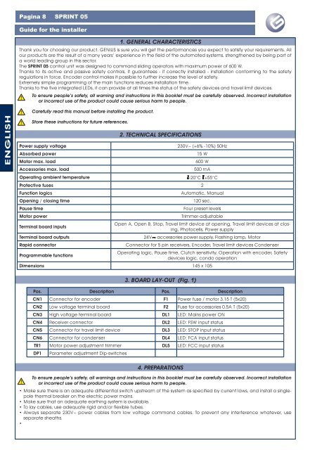
Pagina <strong>SPRINT</strong> <strong>05</strong>Guide for the installer1. GENERAL CHARACTERISTICSThank you for choosing our product. GENIUS is sure you will get the performances you expect to satisfy your requirements. Allour products are the result of a many years’ experience in the field of the automated systems, strengthened by being part ofa world leading group in this sector.The <strong>SPRINT</strong> <strong>05</strong> control unit was designed to command sliding operators with maximum power of 600 W.Thanks to its active and passive safety controls, it guarantees - if correctly installed - installation conforming to the safetyregulations in force. Encoder control makes it possible to further increase the level of safety.Extremely simple programming of the main functions reduces installation time.Thanks to the five integrated LEDs, it can provide at all times the status of the safety devices and travel limit devices.To ensure people’s safety, all warning and instructions in this booklet must be carefully observed. Incorrect installationor incorrect use of the product could cause serious harm to people.Carefully read this manual before installing the product.ENGLISHStore these instructions for future references.Power supply voltageAbsorbed powerMotor max. loadAccessories max. loadOperating ambient temperature2. TECHNICAL SPECIFICATIONS230V~ (+6% -10%) 50Hz15 W600 W500 mA-20°C +55°CProtective fuses 2Function logicsOpening / closing timePause timeMotor powerTerminal board inputsAutomatic, Manual120 sec.Four preset levelsTrimmer-adjustableOpen A, Open B, Stop, Travel limit device at opening, Travel limit devices at closing,Photocells, Power supplyTerminal board outputs 24V accessories power supply, Flashing lamp, MotorRapid connectorProgrammable functionsConnector for 5 pin receivers, Encoder, Travel limit devices CondenserOperating logic, Pause time, Clutch sensitivity, Operation with encoder, Safetydevices logic, condo operationDimensions 145 x 1<strong>05</strong>3. BOARD LAY-OUT (Fig. 1)Pos. Description Pos. DescriptionCN1 Connector for encoder F1 Power fuse / motor 3.15 T (5x20)CN2 Low voltage terminal board F2 Fuse for accessories 0.5A T (5x20)CN3 High voltage terminal board DL1 LED: Mains power ONCN4 Receiver connector DL2 LED: FSW input statusCN5 Connector for travel limit device DL3 LED: STOP input statusCN6 Connector for condenser DL4 LED: FCA input statusTR1 Motor power adjustment trimmer DL5 LED: FCC input statusDP1Parameter adjustment Dip-switches4. PREPARATIONSTo ensure people’s safety, all warnings and instructions in this booklet must be carefully observed. Incorrect installationor incorrect use of the product could cause serious harm to people.• Make sure there is an adequate differential switch upstream of the system as specified by current laws, and install a singlepolethermal breaker on the electric power mains.• Make sure that an adequate earthing system is available.• To lay cables, use adequate rigid and/or flexible tubes.• Always separate 230V~ power cables from low voltage command cables. To prevent any interference whatever, useseparate sheaths.•