The Hanau™ Spring-Bow Hanau™ Spring-Bow L'arc ... - Whip Mix
The Hanau™ Spring-Bow Hanau™ Spring-Bow L'arc ... - Whip Mix
The Hanau™ Spring-Bow Hanau™ Spring-Bow L'arc ... - Whip Mix

Create successful ePaper yourself
Turn your PDF publications into a flip-book with our unique Google optimized e-Paper software.
<strong>The</strong> Hanau <strong>Spring</strong>-<strong>Bow</strong><br />
Instruction Manual<br />
Hanau <strong>Spring</strong>-<strong>Bow</strong><br />
Gebrauchsanleitung<br />
L’arc facial flexible<br />
de marque Hanau <br />
Manuel d’utilisation<br />
L’arco-<strong>Spring</strong> Hanau <br />
Manuale D’Istruzione<br />
arco a Resorte <strong>Spring</strong>-<strong>Bow</strong><br />
de Hanau <br />
Manual de Instrucciones
Table of Contents<br />
English ...................................................................................... 1<br />
Deutsch ................................................................................... 11<br />
Français .................................................................................... 21<br />
Italiano ..................................................................................... 31<br />
Español .................................................................................... 41
<strong>The</strong> Hanau <strong>Spring</strong>-<strong>Bow</strong><br />
<strong>The</strong> HANAU SPRING-BOW is an Earpiece type,<br />
used to capture the record of a patient’s maxillary arch<br />
and its relation to the external auditory meatus. It is<br />
capable of preserving this clinically acceptable relation<br />
and to transfer it onto a HANAU Articulator.<br />
AUTOCLAVABLE…<br />
SELF-CENTERING…<br />
COMFORTABLE…<br />
RAPID<br />
Uses the ANTERIOR PATIENT REFERENCE<br />
of the INFRA-ORBITALE NOTCH and the POS-<br />
TERIOR PATIENT REFERENCE at the PORION,<br />
the superior border of the ExTERNAL AUDITORy<br />
MEATUS.<br />
Both references form the anatomical FRANk-<br />
FORT HORIzONTAL PLANE; the plane upon<br />
which this HANAU <strong>Spring</strong>-<strong>Bow</strong> is based.<br />
<strong>The</strong> patient related <strong>Spring</strong>-<strong>Bow</strong> suspends DIRECT-<br />
Ly from the Articulator for attaching the maxillary<br />
cast or–<br />
the <strong>Spring</strong>-<strong>Bow</strong> may remain in the operatory and<br />
the maxillary cast attached INDIRECTLy by using<br />
an accessory Mounting Platform No. 010356-000.<br />
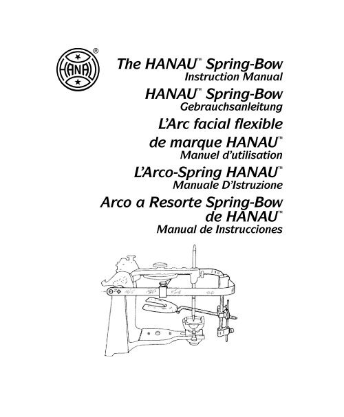
<strong>The</strong> Item No. 010328-0 HANAU <strong>Spring</strong>-<strong>Bow</strong>,<br />
Figure 1, includes:<br />
(1) <strong>Bow</strong>, Part No. 010355-000<br />
(1) Transfer Clamp Assembly, Part No. 01356-000<br />
(1) Anterior Elevator, Part No. 010358-000<br />
(1) Bitefork, Part No. 005751-000<br />
005751-000<br />
010358-000<br />
010355-000<br />
010356-000<br />
Figure 1<br />
Parallel to<br />
Sagittal<br />
Bitefork PreParation<br />
DENTULOUS - <strong>The</strong> Bitefork is covered with a triple<br />
layer of hard baseplate wax or compound, suitable<br />
for obtaining an occlusal imprint of the maxillary<br />
cusps, Figure 2.<br />
<strong>The</strong> softened impression material on the Bitefork<br />
is seated against the maxillary occlusal surface to<br />
create a distinct cuspal imprint without metal contact.<br />
Note that the stem of the Bitefork must extend<br />
approximately parallel to the sagittal plane and be at<br />
the left side of the patient.<br />
Chill the wax occlusal imprint and check it against<br />
the maxillary cast for accurate seating. Relieve any<br />
tissue bearing surface which may interfere.<br />
Heat and<br />
Pierce<br />
Maxillary Cast<br />
Wax Rim<br />
Parallel to<br />
Sagittal<br />
Covered Fork<br />
Stem at Left<br />
Figure 2<br />
Stem at<br />
Left<br />
Figure 3<br />
EDENTULOUS - Attach the Bitefork to the maxillary<br />
occlusal rim by heating the tines and piercing<br />
them fully into the wax rim, Figure 3.<br />
<strong>The</strong> “tines” shall be parallel to the occlusal plane,<br />
perhaps 3 mm from the occlusal surface and shall not<br />
distort the occlusal surface. <strong>The</strong> stem of the Bitefork<br />
shall be at the patient’s left and be approximately<br />
parallel to the sagittal plane, Figure 4. <strong>The</strong> assembly<br />
shall form a rigid occlusal rim/bitefork stem assembly,<br />
as though in one piece.<br />
1
Do Not<br />
Distort<br />
Occlusal<br />
Surface<br />
An alternative to piercing the wax rim is to fabricate<br />
an occlusal index on the Bitefork.<br />
Figure 5 illustrates the Bitefork stem at the patient’s<br />
left, covered with a triple layer of hard baseplate wax<br />
or whatever your selection. Heat seal the periphery<br />
and soften throughout in a water bath. Seat and hand<br />
mold the wax around the rim and chill to assure<br />
removal and accurate replacement of the wax rim in<br />
its indexed bite.<br />
<strong>Bow</strong> PreParation<br />
1. Finger attach the Earpieces to <strong>Bow</strong> using the<br />
knurled Thumbnuts, Figure 6. No wrenches are<br />
necessary with the HANAU <strong>Spring</strong>-<strong>Bow</strong>.<br />
2. Note that the Thumbscrew is finger tightened to<br />
retain the Anterior Patient Reference in the nonhazardous<br />
position illustrated.<br />
2<br />
Parallel to<br />
Sagittal<br />
Wax Rim<br />
Pierced and<br />
Rigid<br />
Wax Covered<br />
Molded to<br />
Occlusal Plane<br />
Figure 4<br />
Stem at Left<br />
Figure 5<br />
Earpiece<br />
Thumbnut<br />
Anterior<br />
Patient<br />
Reference<br />
Thumbscrew<br />
<strong>Bow</strong><br />
Figure 6<br />
3. Insert the Transfer Rod into the <strong>Bow</strong> Socket, Figure<br />
7. Align the “flatted” side toward the front and<br />
insert to the Rubber Ring “stop.” Finger tighten<br />
the tapered Thumbscrew against the “flatted” side<br />
of the Transfer Rod.<br />
Note the position of Clamps, illustrated.<br />
4. Loosen the Thumbscrews at No. 3 and 2 on the<br />
Bitefork Clamp and then Thumbscrew No. 1 on<br />
the Transverse Clamp.<br />
A light application of petroleum jelly on the<br />
Transfer Rod and Transverse Rod will assist<br />
Clamp positioning during patient application.<br />
<strong>Bow</strong><br />
Transfer Rod<br />
<strong>Bow</strong> Socket<br />
Transverse Rod<br />
Transverse Clamp<br />
Thumbscrew No. 1<br />
Tapered Thumbscrew<br />
“Flatted” Side<br />
Rubber Ring<br />
Thumbscrew No. 2<br />
Thumbscrew No. 3<br />
Bitefork Clamp<br />
Figure 7<br />
Patient aPPlication<br />
5. Accurately seat the prepared Bitefork to the<br />
patient, perhaps placing two cotton rolls between<br />
the mandibular occlusal surface and the underside<br />
of the Bitefork, Figure 8. Apply a “touch” of<br />
petroleum jelly on the stem end of the Bitefork.
Maxillary<br />
Input<br />
Instruct the patient to gently close and firmly<br />
support the Bitefork in this accurate and immobile<br />
maxillary occlusal registration.<br />
<strong>The</strong> imprint or the registration of the maxillary<br />
shall be used for orienting the upper cast to the<br />
Articulator. No concern is to be given to the mandible<br />
as its function in this instance is ONLy to<br />
hold the Bitefork securely against the maxillary<br />
arch.<br />
6. Figure 9 depicts the stem of the Bitefork entering<br />
the loose Bitefork Clamp. Slide this Clamp<br />
① onto the stem perhaps 4 centimeters and then<br />
“<strong>Spring</strong> open” the <strong>Bow</strong> ② and swing it downward<br />
as ③ to allow the Earpieces to enter the the external<br />
auditory meatus.<br />
3<br />
Earpieces<br />
in External<br />
Auditory<br />
Meatus<br />
Swing<br />
Insert Bitefork<br />
and Close Firmly<br />
2<br />
<strong>Spring</strong><br />
Open<br />
Swing<br />
4 cm 1<br />
Bitefork Stem<br />
Figure 8<br />
Earpieces<br />
<strong>Bow</strong><br />
Bitefork Clamp<br />
Stem of<br />
Bitefork<br />
Figure 9<br />
7. Slightly loosen the spring loaded Thumbscrew<br />
that secures the Anterior Patient Reference,<br />
Figure 10. Carefully rotate this Reference Orbitale<br />
Pointer) to a proximity with the patient’s infraorbitale<br />
notch.<br />
Elevate the <strong>Bow</strong> at the Transfer Rod to align the<br />
top of this Reference with the patient’s orbitale.<br />
This patient landmark is the lowest point on the<br />
infra-orbitale rim and is the anterior reference of<br />
the Frankfort Horizontal Plane.<br />
<strong>The</strong> top of the Earpiece relates against the porion<br />
which is said to be the posterior reference of<br />
the Frankfort. <strong>The</strong> superior surface of the temple<br />
portion of the <strong>Bow</strong> now visually represents the<br />
true Frankfort Horizontal Plane.<br />
8. Tighten the Clamp Thumbscrews in the suggested<br />
order, grasping the <strong>Bow</strong> to offset torquing and<br />
patient discomfort. A trial run of these Clamps is<br />
suggested before the patient application to recognize<br />
the amount of tightening necessary.<br />
Thumbscrew<br />
Anterior Patient<br />
Reference<br />
(Orbitale Pointer)<br />
Patient’s<br />
Infra-Orbitale<br />
Notch<br />
<strong>Bow</strong><br />
No. 2<br />
No. 3<br />
No. 1<br />
Transfer Rod<br />
Figure 10<br />
A. Thumbscrew No. 1 - hold the right side of <strong>Bow</strong><br />
while securing the Transverse Clamp to the<br />
Transfer Rod.<br />
B. Carefully rotate the Anterior Patient Reference<br />
away from the patient. Store this Reference by<br />
swinging it forward to the right temple of the<br />
<strong>Bow</strong> and lightly engage the Thumbscrew.<br />
C. Thumbscrew No. 2 - hold the right side of<br />
<strong>Bow</strong> while tightening the Bitefork Clamp to<br />
the Transverse Rod.<br />
3
D. Thumbscrew No. 3 - continue to hold the right<br />
corner of the <strong>Bow</strong> and tighten the Bitefork<br />
clamp to the stem of the Bitefork.<br />
9. Instruct the patient to “open,” releasing the Bitefork<br />
registration from the maxillary dental arch.<br />
Grasp the posterior ends of the <strong>Bow</strong> and release<br />
the Earpieces from the meatus. Withdraw the<br />
complete assembly from the patient with the Bitefork<br />
index rigidly attached to the bow.<br />
10. Recognizing that the <strong>Spring</strong>-<strong>Bow</strong> may be compromised<br />
by inadequately tightened Thumbscrews,<br />
<strong>Whip</strong> <strong>Mix</strong> offers an accessory Allen Wrench No.<br />
005125-000 to preserve their integrity.<br />
During patient recording OR immediately upon<br />
removal of the <strong>Bow</strong> assembly from the patient,<br />
the Thumbscrews may additionally secured by<br />
a Wrench. Tighten the socket screw head of the<br />
Thumbscrew in the absolute order of No.1, No.<br />
2, and No. 3 illustrated, Figure 11.<br />
Direct-Mounting Hanau <br />
SPring-<strong>Bow</strong><br />
LABORATORy PROCEDURE: <strong>The</strong> patient related<br />
HANAU <strong>Spring</strong>-<strong>Bow</strong> is consigned to the laboratory<br />
and is to be used for anatomically mounting the<br />
maxillary cast onto a HANAU Articulator.<br />
SPring-<strong>Bow</strong> SuSPenSion<br />
11. <strong>The</strong> Earpieces represent the external auditory<br />
meatus and they have small vent holes in their<br />
ends. <strong>The</strong>se Earpieces suspend the <strong>Bow</strong> directly<br />
over the Auditory Pins on the HANAU 96H2<br />
and HANAU-MATE ® Series of Articulators, Figure<br />
12A.<br />
4<br />
No. 1<br />
No. 2<br />
No. 3<br />
005125-000<br />
Allen Wrench<br />
Accessory<br />
Figure 11<br />
Auditory Pins<br />
Earpiece<br />
Figure 12A<br />
A 5/32" diameter hole, 12mm anterior to the<br />
Earpiece center, represents the condyle center<br />
of the patient. <strong>The</strong> HANAU Wide-Vue, Radial-Shift<br />
and Modular Series of Articulators will<br />
specify removing the Earpieces and suspending<br />
the 5/32" dia. holes in the <strong>Bow</strong> over the Condylar<br />
Shaft Ends on the Articulator, Figure 12B.<br />
Condylar Shaft End<br />
Earpiece Hole<br />
5/32” Diameter Hole<br />
Figure 12B<br />
anterior elevator<br />
12. <strong>The</strong> Anterior Elevator, 010358-000, slides onto<br />
the Transfer Rod, Figure 13. Place the larger hole<br />
first and twist the Elevator over and onto the<br />
Rubber Ring, the Elevating Pin and Thumbscrew<br />
toward the front. Slide the Elevating Pin to its<br />
uppermost position and secure by Thumbscrew.
Transfer Rod<br />
Rubber Ring<br />
Larger Hole<br />
vertical lanDMarkS<br />
13. Some HANAU Articulators are furnished with<br />
an Orbitale Indicator as an anatomical simulation<br />
of the patient’s infra-orbitale notch. <strong>The</strong> top of the<br />
Anterior Patient Reference (orbitale pointer) on<br />
the <strong>Spring</strong>-<strong>Bow</strong> shall be aligned to the underside<br />
of this Orbitale Indicator, Figure 14A.<br />
Reference at Underside of<br />
Orbitale Indicator<br />
Orbitale Indicator<br />
Figure 14A<br />
Should the Articulator not be equipped with an<br />
Orbitale Indicator, the top of the Anterior Patient<br />
Reference will be aligned to an acceptable substitute–the<br />
bottom of the Mounting Plate, Figure<br />
14B.<br />
Reference at Bottom of<br />
Mounting Plate<br />
Anterior Elevator<br />
Thumbscrew<br />
Mounting Plate<br />
Elevating Pin<br />
Figure 13<br />
Figure 14B<br />
<strong>The</strong> HANAU-MATE ® has none of these references.<br />
A suitable substitute is to align the top of<br />
the Anterior Patient Reference about one and onehalf<br />
millimeters (1/16”) below the underside of<br />
the Upper Member, Figure 14C.<br />
Upper member<br />
Reference 1/16” below<br />
Upper Member<br />
Mounting tHe Maxillary caSt<br />
14. Rotate the Anterior Patient Reference to its storage<br />
position at the side of the <strong>Bow</strong>.<br />
15. <strong>The</strong> Bitefork index must be adequately supported<br />
before placement of the maxillary cast and stone<br />
or plaster mounting to the Articulator.<br />
An accessory HANAU Cast Support, Item No.<br />
003401-000 is offered to support the Bitefork and<br />
maintain its position when adding the cast weight<br />
and stone mix, Figure 15.<br />
003401-000<br />
Figure 14C<br />
Figure 15<br />
5
16. Seat and lute the maxillary cast in the occlusal<br />
index of the Bitefork, Figure 16.<br />
17. <strong>The</strong> upper member of the Articulator is swung<br />
open and the mixture of stone is placed on the<br />
maxillary cast. <strong>The</strong> Upper Member is immediately<br />
closed to embed the Mounting Plate and to<br />
bring the Incisal Pin into contact with the Incisal<br />
Table.<br />
Complete the mounting, removing excess material<br />
to assure convenient removal and accurate<br />
reattachment of the cast to the Articulator.<br />
18. Upon complete set of the mounting, disengage<br />
the cast from the Bitefork index and remove the<br />
<strong>Spring</strong>-<strong>Bow</strong> and supporting means.<br />
<strong>The</strong> maxillary mount has been completed.<br />
6<br />
Embed<br />
Mounting Plate<br />
Maxillary Cast<br />
Support Bitefork Index<br />
Incisal Pin<br />
Contact<br />
Figure 16<br />
aDDitional Hanau SPring-<strong>Bow</strong><br />
caPaBility<br />
An accessory Mounting Platform/Cast Support,<br />
Item No. 010342-000 is available for INDIRECT<br />
MOUNTING of the maxillary cast, Figure 17.<br />
<strong>The</strong> INDIRECT method allows the <strong>Spring</strong>-<strong>Bow</strong><br />
to remain in the dental operatory. <strong>The</strong> Transfer Rod/<br />
Biteplane assembly with casts or impressions and<br />
interocclusal records are sent to the laboratory for<br />
mounting. <strong>The</strong> maxillary cast is accurately related by<br />
the Transfer Rod placement in the Mounting Platform<br />
010342-000. This Platform is used on HANAU <br />
Articulator Models as,<br />
ALL 96H2 Series<br />
ALL 158 Wide-Vue Series<br />
ALL 165 HANAU-MATE ®<br />
ALL 166 Radial Shift<br />
ALL 181 Condyle Repositioner<br />
ALL 183/184 Wide-Vue Series<br />
ALL 190/192 Modular Systems<br />
010342-000<br />
Figure 17
Consider an additional Transfer Clamp Assembly,<br />
Item No. 010356-000 and Bitefork 005726-000. A<br />
biteplane (perforated for index material adhesion),<br />
Item No. 005753-000 is recommended for occlusal<br />
cusp prints of the maxillary teeth. <strong>The</strong>se additional<br />
adjuncts in effect become an additional <strong>Spring</strong>-<strong>Bow</strong>–<br />
doubling or tripling <strong>Bow</strong> use while the Bitefork index<br />
awaits later laboratory mounting.<br />
010356-000 005726-000<br />
005753-000<br />
Additional adaptations to Articulators other than<br />
the premier HANAU line are described in the<br />
HANAU catalog and price list.<br />
Maintenance<br />
Sterilization is accomplished by steam autoclave<br />
of the complete <strong>Spring</strong>-<strong>Bow</strong> and/or any part of it<br />
thereof.<br />
Routinely, and especially after autoclave, apply<br />
a handpiece type of oil to all moving and threaded<br />
joints to assure free and continued movement.<br />
SteriliZe Before uSe.<br />
Do not Dry Heat SteriliZe.<br />
7
articulator Preparation and <strong>Spring</strong>-<strong>Bow</strong> attachment<br />
Locked in<br />
Centric<br />
Auditory<br />
Pin<br />
8<br />
Mounting Plate<br />
70˚<br />
Condylar<br />
Inclination<br />
Auditory<br />
Pin<br />
30˚ Bennett<br />
30˚<br />
70˚ Condylar<br />
Condylar Inclination<br />
Inclination<br />
Condylar<br />
Shaft End<br />
Close<br />
Tapered Pin<br />
zero Bennett<br />
Locked in<br />
Centric<br />
Incisal Pin<br />
Flush with<br />
Top<br />
zero<br />
Degree<br />
Earpieces<br />
over<br />
Auditory<br />
Pins<br />
Reference at<br />
Underside of Orbitale<br />
Indicator or Underside of<br />
Mounting Plate<br />
96H2 SerieS, serial 123,714 and above<br />
Registration<br />
Groove<br />
Mounting<br />
Plate<br />
Earpieces<br />
over<br />
Auditory<br />
Pins<br />
Reference at<br />
1/16” below<br />
Upper Member<br />
165 Hanau-Mate ®<br />
Mid-Line<br />
zero<br />
Degree<br />
<strong>Bow</strong> Suspended<br />
from Condylar<br />
Shaft Ends<br />
Reference at<br />
Underside of<br />
Orbitale Indicator<br />
184/183 wiDe-vu SerieS<br />
Elevating Pin<br />
Elevating Pin<br />
Elevating Pin<br />
Earpieces<br />
Removed<br />
Lock<br />
Thumbscrew<br />
Lock<br />
Thumbscrew<br />
Lock<br />
Thumbscrew
zero Degree<br />
Condylar<br />
Inclination<br />
Condylar<br />
Shaft<br />
End<br />
Locked in<br />
Centric<br />
zero Degree<br />
Condylar<br />
Inclination<br />
Condylar<br />
Shaft End<br />
zero Degree<br />
Condylar<br />
Inclination<br />
6˚ Bennett<br />
3 mm<br />
Radial<br />
Shift<br />
70˚<br />
Condylar<br />
Inclination<br />
Condylar<br />
Shaft End<br />
Locked In<br />
Centric<br />
30˚ Bennett<br />
Mounting Plate<br />
Mid-Line<br />
zero<br />
Degree<br />
<strong>Bow</strong> Suspended<br />
from Condylar<br />
Shaft Ends<br />
Reference at<br />
Underside of<br />
Mounting Plate<br />
Elevating Pin<br />
190 MoDular SySteM with adjustable Bennett fossae<br />
Locked in<br />
Centric<br />
Mounting Plate<br />
Mid-Line<br />
zero<br />
Degree<br />
<strong>Bow</strong> Suspended<br />
from Condylar<br />
Shaft Ends<br />
Reference at<br />
Underside of<br />
Mounting Plate<br />
Elevating Pin<br />
192 MoDular SySteM with Programmed fossae<br />
Mounting<br />
Plate <strong>Bow</strong> Suspended<br />
from Condylar<br />
Shaft Ends<br />
Mid-Line<br />
zero<br />
Degree<br />
Reference at<br />
Underside of<br />
Mounting Plate<br />
Elevating Pin<br />
194 MoDular SySteM with radial Shift condyle<br />
Earpieces<br />
Removed<br />
Earpieces<br />
Removed<br />
Lock<br />
Thumbscrew<br />
Lock<br />
Thumb screw<br />
Earpieces<br />
Removed<br />
Lock<br />
Thumbscrew<br />
9
additional articulator adaptations<br />
<strong>The</strong> HANAU 96H2 Series, serial 123,713 and<br />
below require the accessory Condyle Transfer Set<br />
010318-000 illustrated, Figure 18.<br />
<strong>The</strong> Earpieces are removed and the Condyle Adaptors<br />
are attached as Figure 19. <strong>The</strong>se Adaptors use the<br />
5/32” diameter holes, 12mm anterior to the Earpiece<br />
center and represent the condyle center. In turn they<br />
suspend the <strong>Spring</strong>-<strong>Bow</strong> from the Condylar Shaft<br />
ends.<br />
Locked in<br />
Centric<br />
Condylar<br />
Shaft<br />
End<br />
10<br />
30˚<br />
Condylar<br />
Inclination<br />
15˚ Bennett<br />
Mounting Plate<br />
Figure 18<br />
Flush<br />
with<br />
Top<br />
zero<br />
Degree<br />
Condylar Shaft End<br />
5/32” Dia. Hole<br />
010318-000<br />
Condyle Transfer Set.<br />
(Suspended <strong>Bow</strong> from<br />
Condylar Shaft Ends)<br />
010318-000<br />
Adaptors over<br />
Condylar<br />
Shaft<br />
Ends<br />
Reference at<br />
Underside of<br />
Orbitale Indicator<br />
96H2 SerieS, serial 123,713 and below<br />
Elevating Pin<br />
Figure 19<br />
Earpieces<br />
Removed and<br />
Adaptors<br />
Attached<br />
Lock<br />
Thumbscrew
Hanau SPRInG-BOW<br />
Der HANAU SPRING-BOW wird in den Ohren<br />
befestigt. Bei seiner Anwendung wird der Maxillärbogen<br />
des Patienten und das Verhältnis zum äußeren<br />
Gehörgang nachvollzogen. Er kann dieses klinisch<br />
akzeptierbare Verhältnis erhalten und auf den Hanau<br />
Artikulator übertragen.<br />
AUTOkLAVIERBAR<br />
SELBSTzENTRIEREND<br />
kOMFORTABEL<br />
SCHNELL<br />
Verwendet die ANTERIORE PATIENTENREFE-<br />
RENz der INFRA-ORBITALEN kERBE –<br />
und die POSTERIORE PATIENTENREFERENz<br />
am PORION, der oberen Grenze des ÄUSSEREN<br />
GEHÖRGANGS.<br />
Beide Referenzen zusammen ergeben die anatomische<br />
FRANkFORT HORIzONTALEBENE, d.h.,<br />
die Ebene, auf der sich dieser Hanau <strong>Spring</strong>-<strong>Bow</strong><br />
begründet.<br />
Der patientenorientierte <strong>Spring</strong>-<strong>Bow</strong> wird DIREkT<br />
am Artikulator aufgehängt und dient der Befestigung<br />
des Maxillärabdrucks, oder –<br />
der <strong>Spring</strong>-<strong>Bow</strong> kann in Verwendung bleiben, und<br />
der Maxillärabdruck wird INDIREkT mit Hilfe einer<br />
Montageplattform, ACCESSORy Mounting Platform<br />
No. 010342-000, befestigt.<br />
Artikel 010328-0 Hanau <strong>Spring</strong>-<strong>Bow</strong>, Abbildung<br />
1, enthält:<br />
(1) Bogen, Best.-Nr. 010355-000<br />
(1) Transfer-klemmensatz, Best.-Nr. 010356-000<br />
(1) Anterior Elevator, Best.-Nr. 010358-000<br />
(1) Bißgabel, Best.-Nr. 005751-000<br />
005751-000<br />
010358-000<br />
010355-000<br />
010356-000<br />
Abbildung 1<br />
Parallel zur<br />
Sagittalebene<br />
vorBereitung Der BiSSgaBel<br />
PATIENT MIT zÄHNEN – Die Bißgabel ist von<br />
einer dreifachen Lage hartem Basisplattenwachs oder<br />
einem Verbindungsmaterial umgeben, womit ein<br />
Okklusalabdruck der maxillären Eckzähne hergestellt<br />
werden kann (siehe Abbildung 2).<br />
Das erweichte Abdruckmaterial an der Bißgabel<br />
befindet sich an der maxillären Okklusaloberfläche, so<br />
daß ein deutlicher Abdruck der Eckzähne ohne Metallkontakt<br />
möglich ist. Es ist zu beachten, daß der Stiel<br />
der Bißgabel ungefähr parallel zur Sagittalebene und<br />
auf der linken Seite des Patienten verlaufen muß.<br />
Den Wachsokklusalabdruck abkühlen und mit<br />
dem Maxillärabdruck für akkuraten Einsatz vergleichen.<br />
Alle Störungen des gewebetragenden Materials<br />
beheben.<br />
Erhitzen und<br />
einstechen<br />
Maxillärabdruck<br />
Wachsrand<br />
Parallel zur<br />
Sagittalebene<br />
Wachsumgebene<br />
Bißgabel<br />
Stiel auf der<br />
linken Siete<br />
Abbildung 2<br />
Stiel auf<br />
der linken<br />
Siete<br />
Abbildung 3<br />
PATIENT zAHNLOS – Die Bißgabel am maxillären<br />
Okklusalrand durch Erhitzen der zinken und vollständiges<br />
Einstechen in den Wachsrand befestigen<br />
(siehe Abbildung 3).<br />
Die “zinken” sollten parallel zur Okklusalebene<br />
sein, ca. 3 mm von der Okklusaloberfläche entfernt,<br />
und sollten diese nicht verziehen. Der Stiel der Bißgabel<br />
sollte sich auf der linken Seite des Patienten<br />
11
efinden und ungefähr parallel zur Sagittalebene verlaufen<br />
(siehe Abbildung 4). Der Satz sollte eine steife<br />
Einheit aus Okklusalrand/Bißgabelstiel bilden.<br />
Okklusaloberfläche<br />
nicht verziehen<br />
Als Alternative zum Einstechen in den Wachsrand<br />
kann ein Okklusal-Index an der Bißgabel hergestellt<br />
werden.<br />
Parallel zur<br />
Sagittaleberne<br />
In Abbildung 5 wird gezeigt, daß sich der Stiel der<br />
Bißgabel auf der linken Seite des Patienten befindet<br />
und die Bißgabel mit einer dreifachen Schicht von<br />
hartem Basisplattenwachs oder sonstigem Material<br />
je nach Wahl umgeben ist. Die Peripherie durch<br />
Erhitzen abdichten und im Wasserbad gründlich<br />
erweichen. Das Wachs um den Rand herum auftragen<br />
und mit der Hand anmodellieren, dann zum Herausnehmen<br />
und für akkurate Plazierung des Wachsrandes<br />
im Index abkühlen.<br />
vorBereitung DeS BogenS<br />
1. Die Ohrbügel manuell mit Hilfe der gerändelten<br />
Flügelmuttern (siehe Abbildung 6) am Bogen<br />
12<br />
Wachsrand<br />
Eingestochen<br />
und steif<br />
Wachsbedeckt<br />
An die Okklusalebene<br />
anmodelliert<br />
Abbildung 4<br />
Stiel auf der<br />
linken Seite<br />
Abbildung 5<br />
anbringen. Für den Hanau <strong>Spring</strong>-<strong>Bow</strong> sind keine<br />
Schraubenschlüssel erforderlich.<br />
2. Bitte beachten: Die Flügelschraube mit den<br />
Fingern anziehen, so daß die anteriore Patientenreferenz<br />
wie illustriert sicher positioniert bleibt.<br />
Ohrbügel<br />
Flügelmutter<br />
Anteriore<br />
Patientenreferenz<br />
Flügelschraube<br />
Bogen<br />
Abbildung 6<br />
3. Die Transferstange in den Bogensockel einsetzen<br />
(siehe Abbildung 7). Die abgeflachte Seite auf die<br />
Vorderseite ausrichten und bis zum Gummiring<br />
einschieben. Die zugespitzte Flügelschraube mit<br />
den Fingern gegen die “abgeflachte” Seite der<br />
Transferstange anziehen.<br />
Die Position der klemmen beachten (siehe Illustration)<br />
4. Flügelschrauben 3 und 2 an der Bißgabelklemme<br />
und danach Flügelschraube 1 an der Transversalklemme<br />
lockern.<br />
Eine dünne Schicht Vaseline auf der Transfer-<br />
sowie Transversalstange unterstützt die klemmenpositionierung<br />
bei der Patientenapplikation.<br />
Bogen<br />
Transferstange<br />
Transversalstange<br />
Transversalklemme<br />
Flügelschraube 1<br />
zugesptitzte Flügelschraube<br />
“Abgeflachte” Seite<br />
Gummiring<br />
Flügelschraube 2<br />
Flügelschraube 3<br />
Bißgabelklemme<br />
Abbildung 7
aPPlikation aM Patienten<br />
5. Die vorbereitete Bißgabel akkurat am Patienten<br />
anbringen, ggf. zwei Watterollen zwischen die<br />
mandibuläre Okklusaloberfläche und die Unterseite<br />
der Bißgabel legen (siehe Abbildung 8). Ein<br />
wenig Vaseline leicht auf das Stielende der Bißgabel<br />
auftragen.<br />
Maxilläreingang<br />
Den Patienten anweisen, den Mund vorsichtig<br />
zu schließen und die Bißgabel bei dieser maxillären<br />
Okklusalregistration akkurat und unbeweglich<br />
zu halten.<br />
Der Abdruck bzw. die Registration des Oberkiefers<br />
ist für die Orientierung des oberen Abdrucks<br />
mit dem Artikulator zu verwenden. Der Unterkiefer<br />
ist hierbei zu vernachlässigen, da dessen EINzIGE<br />
Funktion in diesem Fall das Fest halten der<br />
Bißgabel gegen den maxillären Bogen ist.<br />
3<br />
Nach unten<br />
schwingen<br />
Ohrbügel<br />
im äußeren<br />
Gehörgang<br />
Bißgabel einsetzen<br />
und fest schliessen<br />
2<br />
Feder<br />
offen<br />
Nach<br />
unten<br />
schwingen<br />
4 cm 1<br />
Stiel der<br />
Bißgabel<br />
Abbildung 8<br />
Ohrbügel<br />
Bogen<br />
Bißgabelklemme<br />
Bißgabelstiel<br />
Abbildung 9<br />
6. Abbildung 9 zeigt das Eintreten des Bißgabelstiels<br />
in die gelockerte Bißgabelklemme. Diese<br />
klemme (1) ca. 4 cm weit auf den Stiel schieben,<br />
dann den Bogen “auffedern” lassen (2) und nach<br />
unten schwingen (3), so daß die Ohrbügel in den<br />
äußeren Gehörgang eintreten können.<br />
Den Bogen freigeben, so daß die Ohrbügel von<br />
der “Feder” komfortabel eingesetzt werden können.<br />
Die Enden der Ohrbügel leicht drücken und<br />
visuell sicherstellen, daß die Ohrbügel im Gehörgang<br />
sitzen.<br />
7. Die federgelagerte Flügelschraube, mit der die<br />
anteriore Patientenreferenz befestigt ist, etwas<br />
lockern (siehe Abbildung 10). Diese Referenz<br />
(Orbitalzeiger) vorsichtig rotieren, bis sie sich<br />
nahe der infra-orbitalen kerbe des Patienten<br />
befindet.<br />
Den Bogen an der Transferstange anheben, so<br />
daß die Referenzoberseite auf die Augenhöhle des<br />
Patienten ausgerichtet ist.<br />
Dieser Orientierungspunkt am Patienten ist der<br />
niedrigste Punkt am infra-orbitalen Rand und<br />
stellt die anteriore Referenz der Frankfort Horizontalebene<br />
dar.<br />
Die Oberseite des Ohrbügels bezieht sich<br />
auf das Porion, das die posteriore Referenz der<br />
Frankfort Horizontalebene darstellt. Die superiore<br />
Fläche des Bogenschläfenteils ist nun eine<br />
visuelle Darstellung der wahren Frankfort Horizontalebene.<br />
Flügelschraube<br />
Anteriore<br />
Patientenreferenz<br />
(Orbitalzeiger)<br />
Infra-Orbitale<br />
kerbe des<br />
Patienten<br />
Nr. 2<br />
Nr. 3<br />
Nr. 1<br />
Bogen<br />
Transferstange<br />
Abbildung 10<br />
13
8. Die Flügelschrauben der klemme in vorgeschlagener<br />
Reihenfolge festziehen. Dabei den Bogen<br />
festhalten, um dessen Verdrehung zu verhüten<br />
und den Patienten zu schonen. Eine probeweise<br />
Befestigung der klemmen vor der Patientenapplikation<br />
wird angeraten, um das Ausmaß des Festziehens<br />
festzustellen.<br />
A. Flügelschraube Nr. 1 – Rechte Bogenseite festhalten,<br />
während die Transversalklemme an der<br />
Transferstange befestigt wird.<br />
B. Die anteriore Patientenreferenz vorsichtig vom<br />
Patienten weg rotieren. Diese Referenz durch<br />
Schwingen nach vorn zur rechten Schläfe des<br />
Bogens und leichte Befestigung mit der Flügelschraube<br />
aufbewahren.<br />
C. Flügelschraube Nr. 2 – Rechte Bogenseite festhalten,<br />
während die Bißgabelklemme an der<br />
Transversalstange befestigt wird.<br />
D. Flügelschraube Nr. 3 – Rechte Bogenseite<br />
weiter festhalten und die Bißgabelklemme am<br />
Bißgabelstiel befestigen.<br />
9. Den Patienten anweisen, den Mund zu öffnen,<br />
wodurch die Bißgabelregistration aus dem maxillären<br />
zahnbereich freigegeben wird.<br />
Die posterioren Enden des Bogens greifen und<br />
die Ohrbügel aus dem Gehörgang nehmen. Den<br />
ganzen Satz vom Patienten abnehmen, wobei der<br />
Bißgabel-Index steif am Bogen befestigt bleibt.<br />
10. Da <strong>Spring</strong>-<strong>Bow</strong>s durch unzureichend angezogene<br />
Flügelschrauben beschädigt werden könnten, bietet<br />
<strong>Whip</strong> <strong>Mix</strong> zur Erhaltung ihrer Funktion stüchtigkeit<br />
einen Sechskantsteckschlüssel (Allen Wrench No.<br />
005125-000) als zubehör an.<br />
14<br />
Nr. 1<br />
Nr. 2<br />
Nr. 3<br />
005125-000<br />
Allen Wrench<br />
als zubehör<br />
Abbildung 11<br />
Während der Patientenaufzeichnung ODER<br />
unmittelbar nachdem der Bogen vom Patienten<br />
abgenommen wird, können die Flügelschrauben<br />
zusätzlich mit einem Schraubenschlüssel festge-<br />
zogen werden. Beim Festziehen der Flügelschrauben<br />
ist die in Abbildung 11 gezeigte Reihenfolge<br />
unbedingt einzuhalten (Nr. 1, Nr. 2 und Nr. 3).<br />
Direkte Montage Hanau <br />
SPring-<strong>Bow</strong><br />
LABORVERFAHREN: Der patientenorientierte<br />
HANAU <strong>Spring</strong>-<strong>Bow</strong> wird dem Labor übergeben,<br />
wo er zur anatomischen Montage des Maxillärabdrucks<br />
an einen HANAU Artikulator verwendet<br />
wird.<br />
SPring-<strong>Bow</strong> aufHÄngung<br />
11. Die Ohrbügel stellen den äußeren Gehörgang dar<br />
und haben kleine Luftlöcher an den Enden. Mit<br />
diesen Ohrbügeln wird der Bogen direkt über den<br />
Gehörstiften des Hanau 96H2 und der Hanau-<br />
Mate ® Series Articulators aufgehängt (siehe<br />
Abbildung 12A).<br />
Gehörstifte<br />
Ohrbügel<br />
Abbildung 12A<br />
Ein Loch mit einem Durchmesser von ca. 3<br />
mm, 12 mm anterior von der Mitte der Ohrbügel,<br />
stellt das kondyluszentrum des Patienten dar. Die<br />
Anleitungen für Artikulatoren Hanau Wide-Vue,<br />
Radial-Shift und Modular-Serien geben an, die<br />
Ohrbügel zu entfernen und das 3 mm-Loch in dem<br />
Bogen über den kondylusschaftenden am Artikulator<br />
aufzuhängen (siehe Abbildung 12 B).<br />
kondylus-Shaftende<br />
Loch am Ohrbügel<br />
Loch mit ca. 3 mm Durchmesser<br />
Abbildung 12B
anterior elevator<br />
12. Der Anterior Elevator, 010358-000, gleitet auf die<br />
Transferstange (siehe Abbildung 13). Das größere<br />
Loch zuerst plazieren und den Elevator auf den<br />
Gummiring schieben, wobei der Hebestift und die<br />
Flügelschraube nach vorn zeigen. Den Hebestift<br />
in die oberste Position schieben und mit der Flügelschraube<br />
befestigen.<br />
Transferstange<br />
Gummiring Anteriore<br />
Hebevorrichtung<br />
Grössers Loch<br />
Abbildung 13<br />
vertikale orientierungSPunkte<br />
13. Einige Hanau Artikulatoren sind mit einem<br />
Orbitalindikator ausgerüstet, der die infra-orbitale<br />
kerbe des Patienten anatomisch simuliert.<br />
Die Oberseite der anterioren Patientenreferenz<br />
(Orbitalzeiger) auf dem <strong>Spring</strong>-<strong>Bow</strong> ist auf die<br />
Unterseite dieses Orbitalindikators auszurichten<br />
(siehe Abbildung 14 A).<br />
Referenz an der Unterseite<br />
des Orbitalindikators<br />
Flügelschraube<br />
Hebestift<br />
Orbitalindikator<br />
Abbildung 14A<br />
Wenn der Artikulator keinen Orbitalindikator<br />
hat, wird die Oberseite der anterioren Patientenreferenz<br />
auf einen anderen akzeptierbaren Punkt<br />
ausgerichtet – die Unterseite der Montageplatte<br />
(siehe Abbildung 14 B).<br />
Referenz an der Unterseite<br />
der Montageplatte<br />
Abbildung 14B<br />
HANAU-MATE ® hat keine dieser Referenzen.<br />
Als geeigneter Ersatz wird die Oberseite der anterioren<br />
Patientenreferenz etwa 1,5 mm unterhalb<br />
der Unterseite des Oberteils ausgerichtet (siehe<br />
Abbildung 14 C).<br />
Oberteil<br />
Montageplatte<br />
Abbildung 14C<br />
15
Montage DeS MaxillÄraBDruckS<br />
14. Die anteriore Patientenreferenz zur ihrer Aufbewahrungsposition<br />
seitlich des Bogens rotieren.<br />
15. Der Bißgabel-Index muß vor dem Anbringen des<br />
Maxillärabdrucks und der Stein- oder Gipsmontage<br />
am Artikulator ausreichend gestützt werden.<br />
zur Stütze der Bißgabel und um deren Position<br />
beim Anbringen des Abdruckgewichts und der<br />
Steinmischung zu erhalten, wird HANAU Cast<br />
Support, Artikel-Nr. 003401-000 als zubehör<br />
angeboten (siehe Abbildung 15).<br />
16. Den Maxillärabdruck im Okklusal-Index der Bißgabel<br />
einsetzen und zementieren (siehe Abbildung<br />
16).<br />
17. Der obere Teil des Artikulators wird geöffnet, und<br />
die zementsteinmischung wird auf den Maxillärabdruck<br />
gegeben. Der obere Teil wird sofort<br />
geschlossen, so daß die Montageplatte eingebettet<br />
16<br />
Montageplatte<br />
einbetten<br />
Maxillärabdruck<br />
Bißgabel-index Stützen<br />
kontakt mit<br />
Inzisalsstift<br />
003401-000<br />
Abbildung 15<br />
Abbildung 16<br />
und der Inzisalstift mit der Inzisaltafel in kontakt<br />
gebracht wird.<br />
Die Montage beenden, überflüssiges Material<br />
entfernen, so daß einfaches Herausnehmen<br />
und akkurate Wiederbefestigung des Abdrucks<br />
gewährleistet wird.<br />
18. Wenn die Montage vollständig erhärtet ist, den<br />
Abdruck vom Bißgabel-Index abnehmen und<br />
<strong>Spring</strong>-<strong>Bow</strong> und Stützen entfernen.<br />
Damit ist die Maxillärmontage beendet.<br />
Hanau SPring-<strong>Bow</strong> ZuSÄtZlicHe<br />
fÄHigkeiten<br />
Eine Stütze für die Montageplattform/den Abdruck,<br />
Mounting Platform/Cast Support, Artikel-Nr. 010342-<br />
000, ist für die INDIREkTE MONTAGE des Maxillärabdrucks<br />
erhältlich (siehe Abbildung 17).<br />
Mit der INDIREkTEN METHODE bleibt der<br />
<strong>Spring</strong>-<strong>Bow</strong> in der zahnärztlichen Praxis. Der Transferstangen-/Bißebenensatz<br />
mit Abdrücken und interokklusalen<br />
Aufzeichnungen wird zwecks Montage<br />
an das Labor gesandt. Der Maxillärabdruck wird<br />
durch die Plazierung der Transferstange in der<br />
Montageplattform 010342-000 in das richtige Verhältnis<br />
gebracht. Diese Plattform wird für folgende<br />
HANAU Artikulator-Modelle verwendet:<br />
ALLE 96H2-Serien<br />
ALLE 165 HANAU-MATE ®<br />
ALLE 166 Radial-Shift<br />
ALLE 181 kondylus Repositionierer<br />
ALLE 183 Wide-Vue-Serien<br />
ALLE 190/192 Modularsysteme<br />
010342-000<br />
Abbildung 17
zusätzlich ist der Transferklemmensatz, Transfer<br />
Clamp Assembly, Artikel-Nr. 010356-000, und Bißgabel,<br />
Bitefork, Artikel-Nr. 005726-000, in Erwägung<br />
zu ziehen. Eine Bißebene (durchlöchert für<br />
Anhaften des Indexmaterials), Artikel-Nr. 005753-<br />
000, wird für okklusale maxilläre Eckzahnabdrücke<br />
empfohlen. Diese Hilfsmittel werden dann effektiv<br />
ein zusätzlicher <strong>Spring</strong>-<strong>Bow</strong>, die dessen Wirksamkeit<br />
verdoppeln oder verdreifachen, während der Bißgabel-Index<br />
im Labor montiert wird.<br />
010356-000 005726-000<br />
005753-000<br />
Weitere Adaptionen an Artikulatoren zusätzlich<br />
zu der HANAU Hauptproduktlinie werden im<br />
HANAU katalog und in der Preisliste beschrieben.<br />
wartung<br />
Sterilisierung wird durch Dampf-Autoklavieren<br />
des kompletten <strong>Spring</strong>-<strong>Bow</strong>s oder dessen Teile<br />
durchgeführt.<br />
Etwas Öl, das für Handstücke geeignet ist, sollte<br />
routinemäßig und besonders nach dem Autoklavieren<br />
auf allen Verbindungsgelenken sowie Gewinden<br />
angebracht werden, um unbehinderte und anhaltende<br />
Beweglichkeit zu gewährleisten.<br />
vor geBraucH SteriliSieren<br />
nicHt Mit HeiSSluft<br />
SteriliSieren!<br />
17
Vorbereitung des artikulators und Befestgung des <strong>Spring</strong>-<strong>Bow</strong>s<br />
zentrisch<br />
verschlossen<br />
Gehörstift<br />
70˚<br />
kondylusneigung<br />
Gehörstift<br />
18<br />
Montageplatte<br />
30˚ Bennett<br />
30˚<br />
kondylus- 70˚<br />
neigung Condylar<br />
Inclination<br />
kondylus-<br />
Schaftende<br />
Schliessen<br />
zugespitzter<br />
Stift<br />
Null Bennett<br />
zentrisch<br />
verschlossen<br />
Inzisalstift<br />
eben mit<br />
Oberseite<br />
Null<br />
Grad<br />
Ohrbügel<br />
über<br />
Gehörstiften<br />
Referenz an<br />
der Unterseite des<br />
Orbitalindikators<br />
96H2 SerieS, sere 123,714 und höher<br />
Registrationrille<br />
Montageplatte<br />
Ohrbügel<br />
über<br />
Gehörstiften<br />
Referenz bei<br />
ca. 1,5mm unterhalb<br />
Oberteil<br />
165 Hanau-Mate ®<br />
Mittellinie<br />
Null Grad<br />
Bogen an kondylus-<br />
Schaftenden<br />
aufgehängt<br />
Referenz an<br />
der Unterseite der<br />
Montageplatte<br />
184/183 wiDe-vu SerieS<br />
Hebestift<br />
Hebestift<br />
Hebestift<br />
Ohrbügel<br />
entfernt<br />
Sperr-Flügelschraube<br />
Sperr-Flügelschraube<br />
Sperr-Flügelschraube
0˚<br />
kondylusneigung<br />
kondylus-<br />
Schaftende<br />
zentrisch<br />
verschlossen<br />
0˚<br />
kondylusneigung<br />
kondylus-<br />
Schaftende<br />
0˚<br />
kondylusneigung<br />
6˚ Bennett<br />
3 mm<br />
Radialverschiebung<br />
70˚<br />
Condylar<br />
Inclination<br />
kondylus-<br />
Schaftende<br />
zentrisch<br />
verschlossen<br />
zentrisch<br />
verschlossen<br />
30˚ Bennett<br />
Montageplatte<br />
Mittellinie<br />
Null Grad<br />
Bogen an kondylus-<br />
Schaftenden<br />
aufgehängt<br />
Referenz an<br />
der Unterseite der<br />
Montageplatte<br />
Hebestift<br />
190 MoDularSySteM mit einstellbaren Bennett fossae<br />
Montageplatte<br />
Mittellinie<br />
Null Grad<br />
Bogen an kondylus-<br />
Schaftenden<br />
aufgehängt<br />
Referenz an der<br />
Unterseite der<br />
Montageplatte<br />
Hebestift<br />
192 MoDularSySteM mit programmierten fossae<br />
Montageplatte Bogen an kondylus-<br />
Schaftenden<br />
aufgehängt<br />
Mittellinie<br />
Null Grad<br />
Referenz an der<br />
Unterseite der<br />
Montageplatte<br />
194 MoDularSySteM mit radialverschiebung<br />
Hebestift<br />
Ohrbügel<br />
entfernt<br />
Ohrbügel<br />
entfernt<br />
Sperr-Flügelschraube<br />
Sperr-<br />
Flügelschraube<br />
Ohrbügel<br />
entfernt<br />
Sperr-<br />
Flügelschraube<br />
19
Zusätzliche artikulatoradaptionen<br />
HANAU 96H2Series, Serie 123,713 und darunter,<br />
erfordern das zusätzliche kondylus Transfer-Set<br />
010318-000, wie in Abbildung 18 gezeigt.<br />
Die Ohrbügel werden abgenommen, und die kondylus-Adapter<br />
werden wie in Abbildung 19 gezeigt<br />
angebracht. Für diese Adapter werden die Löcher mit<br />
ca. 3 mm Durchmesser, 12 mm anterior der Ohrbügelmitte<br />
verwendet; sie bedeuten die kondylusmitte.<br />
An ihnen wird wiederum der <strong>Spring</strong>-<strong>Bow</strong> von den<br />
20<br />
zentrichsch<br />
verschlossen<br />
kondylus-<br />
Schaftende<br />
30˚<br />
kondylusneigung<br />
15˚ Bennett<br />
Montageplatte<br />
Abbildung 18<br />
Eben mit<br />
Oberseite<br />
Null Grad<br />
kondylus-schaftenden aufgehängt.<br />
kondylus-Schaftende<br />
Loch mit ca. 3mm<br />
Durchmesser<br />
010318-000<br />
kondylus Transfer-Set<br />
(Bogen wird and kondylus-<br />
Schaftende aufgehängt<br />
010318-000<br />
Adapter über<br />
kondylus-<br />
Schaftende<br />
Referenz an<br />
der Unterseite des<br />
Orbitalindikators<br />
96H2 SerieS, serial 123,713 and below<br />
Hebestift<br />
Abbildung 19<br />
Ohrbügel entfernt<br />
und Adapter<br />
angebracht<br />
Sperr-Flügelschraube
L’arc facial flexible de marque Hanau <br />
L’arc facial flexible HANAU à embouts auditifs<br />
est utilisé pour enregistrer les dimensions de l’arc<br />
maxillaire du patient par référence aux trous auditifs<br />
externes. L’arc est capable de conserver cette mesure<br />
relationnelle, cliniquement acceptée, pour permettre<br />
son transfert à un Articulateur HANAU .<br />
AUTOCLAVABLE<br />
AUTOCENTRABLE<br />
CONFORTABLE<br />
RAPIDE<br />
L’appareil utilise le Pointeur Antérieur de Référence<br />
positionné dans l’Encoche Infra-Orbitale du<br />
patient et la Référence Postérieure du Patient positionnée<br />
au Porion, le bord supérieur du Conduit<br />
Auditif Externe.<br />
Ces deux références constituent le Plan Horizontal<br />
de Frankfort; plan sur lequel cet arc flexible<br />
HANAU est basé.<br />
L’arc flexible relatif au patient se suspend<br />
DIRECTEMENT à l’Articulateur pour permettre<br />
l’attachement du moulage maxillaire oul’arc<br />
flexible peut rester (in the operatory?) et<br />
le moulage maxillaire y être attaché INDIREC-<br />
TEMENT en utilisant une plateforme de montage<br />
AUxILIAIRE n o 010342-000.<br />
L’arc flexible HANAU n o 010328-0, à la figure<br />
1 inclut:<br />
(1) Arc, article n o 010355-000<br />
(1) Ensemble d’attaches de transfert, article n o<br />
010356-000<br />
(1) Elévateur antérieur, article n o 010358-000<br />
(1) Fourchette dentaire, article n o 005751-000<br />
005751-000<br />
010358-000<br />
010355-000<br />
010356-000<br />
Figure 1<br />
parallèle au<br />
plan sagittal<br />
PréParation De la fourcHette<br />
Dentaire<br />
MACHOIRE DENTEE- La fourchette dentaire est<br />
couverte avec une triple couche de cire dure ou compound,<br />
appropriée pour obtenir une empreinte occlusive<br />
des cupsides maxillaires (voir figure 2).<br />
Le matériau d’impression ramolli sur la fourchette<br />
dentaire est placé contre la surface occlusive du maxillaire<br />
afin de créer une empreinte cupsidique distincte,<br />
sans qu’il y ait contact avec la partie métallique de<br />
la fourchette. Notez que le manche de la fourchette<br />
dentaire doit être approximativement parallèle au plan<br />
sagittal et être positionné à la gauche du patient.<br />
Refroidissez l’empreinte occlusive de cire et comparez-la<br />
avec le moulage maxillaire afin d’obtenir un<br />
placement précis. Débarrassez la surface de tout tissu<br />
pouvant interférer.<br />
chauffer et<br />
enfoncer<br />
moulage maxillaire<br />
bordure de cire<br />
parallèle au<br />
plan sagittal<br />
fourchette couverte<br />
manche placé<br />
à gauche<br />
Figure 2<br />
manche<br />
placé à<br />
gauche<br />
Figure 3<br />
MACHOIRE EDENTEE- Attachez la fourchette<br />
dentaire au bord du maxillaire occlusal en chauffant<br />
les dents de la fourchette et en les enfonçant complètement<br />
dans la bordure de cire ( voir figure 3).<br />
21
Les “dents” doivent être positionnées parallèlement<br />
au plan d’occlusion, approximativement à 3mm<br />
de la surface occlusale et ne devraient pas déformer<br />
la surface occlusale.<br />
Le manche de la fourchette dentaire doit être à la<br />
gauche du patient et être approximativement parallèle<br />
au plan sagittal (voir figure 4).<br />
Le montage doit former un ensemble “bordure/<br />
fourchette” rigide comme s’ils ne constituaient<br />
qu’une seule pièce.<br />
ne pas<br />
déformer<br />
la surface<br />
occlusale<br />
Alternativement au percement du bord de cire,<br />
on peut fabriquer un index occlusal sur la fourchette<br />
dentaire.<br />
La figure 5 illustre la fourchette dentaire, manche<br />
positionné à la gauche du patient, couverte avec<br />
une triple couche de cire dure ou de produit de votre<br />
choix. Scellez à chaud la périphérie et ramollissez<br />
l’ensemble dans de l’eau chaude. Placez et moulez<br />
à la main la cire autour du bord et refroidissez pour<br />
assurer l’enlèvement puis le repositionnement précis<br />
de la bordure de cire dans l’empreinte de morsure.<br />
22<br />
parallèle au<br />
plan sagittal<br />
bordure de cire<br />
percé et rigide<br />
couverture de cire<br />
manche à<br />
gauche<br />
Figure 4<br />
Figure 5<br />
PreParation De l’arc<br />
1. Attachez les embouts auditifs à l’arc en vissant<br />
manuellement les écrous à molette (voir figure 6).<br />
L’arc flexible HANAU ne nécessite pas l’usage<br />
de clés à molette.<br />
2. Notez que la vis manuelle est resserrée afin de<br />
positionner le Pointeur de Référence Antérieur<br />
dans la position illustrée, évitant ainsi tout risque<br />
d’accident.<br />
embout<br />
auditif<br />
écrou à molette<br />
manuel<br />
pointeur de<br />
référence antérieur<br />
du patient<br />
3. Insérez la Tige de l’appareillage de Transfert dans<br />
le Trou de l’Arc, comme illustré à la figure 7.<br />
Orientez la face “plate” de la tige vers l’avant<br />
et enfoncez-la jusqu’à l’anneau d’arrêt en caoutchouc.<br />
Resserrez manuellement la vis fuselée<br />
contre la face “plate” de l’extrémité de la tige.<br />
Notez la position des attaches, comme illustré.<br />
4. Désserrez les vis manuelles n o 3 et n o 2 sur l’attache<br />
de la fourchette dentaire, ensuite désserrez la<br />
vis manuelle n o 1 sur l’attache transversale. L’application<br />
de vaseline sur la tige de l’appareil de<br />
transfert et la tige transversale facilitera le positionnement<br />
des attaches lors de l’application de<br />
l’appareillage sur le patient.<br />
arc<br />
tige de l’appareil<br />
de transfert<br />
tige transversale<br />
attache transversale<br />
vis manuelle n o 1<br />
vis manuelle<br />
arc<br />
Figure 6<br />
vis manuelle fuselée<br />
face “plate”<br />
anneau de<br />
caoutchouc<br />
vis manuelle n o 2<br />
vis manuelle n o 3<br />
attache de la<br />
fourchette dentaire<br />
Figure 7
PoSitionneMent Sur le Patient<br />
5. Placez méticuleusement la fourchette dentaire<br />
préparée dans la bouche du patient. Placez éventuellement<br />
deux boules de coton entre la surface<br />
occlusive mandibulaire et la face inférieure de la<br />
fourchette dentaire, voir figure 8. Appliquez une<br />
pointe de vaseline à l’extrémité du manche de la<br />
fourchette dentaire.<br />
entrée<br />
maxillaire<br />
insérez la fourchette dentaire et<br />
demandez de serrer fermement<br />
manche de<br />
la fourchette<br />
dentaire<br />
Figure 8<br />
Demandez au patient de fermer lentement la<br />
mâchoire puis de maintenir fermement la fourchette<br />
dentaire dans cette position immobile d’occlusion<br />
maxillaire.<br />
L’empreinte ou l’enregistrement maxillaire sera<br />
utilisé pour orienter le moulage supérieur sur l’Articulateur.<br />
On ne s’occupera pas du mandibule à<br />
ce stade, sa fonction ici se limitant ExCLUSI-<br />
VEMENT au maintien de la fourchette dentaire<br />
contre l’arc maxillaire.<br />
6. La figure 9 décrit l’entrée du manche de la fourchette<br />
dentaire dans son attache désserrée. En première<br />
étape (1), glissez cette attache sur le manche<br />
de la fourchette sur une distance de ±4 cm.<br />
Ensuite (2), écartez les branches de l’arc flexible<br />
et pivotez-le vers le bas afin de (3) positionner les<br />
embouts auditifs dans les trous auditifs externes.<br />
Relâchez lentement l’arc et laissez la flexibilité<br />
trouver une position confortable dans les trous<br />
auditifs. Appuyez légèrement sur les extrémités<br />
des embouts auditifs et assurez-vous qu’ils sont<br />
bien positionnés dans le trou auditif.<br />
3<br />
pivotez<br />
embouts<br />
auditifs dans<br />
le conduit<br />
auditif externe<br />
2<br />
écartez<br />
pivotez<br />
4 cm 1<br />
embouts<br />
auditifs<br />
attache de la<br />
fourchette dentaire<br />
manche de<br />
la fourchette<br />
dentaire<br />
Figure 9<br />
7. Désserrez légèrement la vis manuelle du Pointeur<br />
de Référence Antérieur du patient située sur<br />
l’arc (figure 10). Faites pivoter précautionneusement<br />
ce pointeur de référence (pointeur orbital) à<br />
proximité de l’encoche infra-orbitale du patient.<br />
Remontez l’arc en le coulissant sur la tige de<br />
l’appareil de transfert afin d’aligner le dessus du<br />
pointeur de référence avec l’orbite du patient.<br />
Le point de repère sur le patient est le point le<br />
plus bas de la bordure infra-orbitale. Il constitue la<br />
référence antérieure du Plan Horizontal de Frankfort.<br />
Le sommet des embouts auditifs, en rapport<br />
avec le Porion, est considéré comme la référence<br />
postérieure de Frankfort. Ainsi, la surface supérieure<br />
temporale de l’arc représente visuellement<br />
le véritable Plan Horizontal de Frankfort.<br />
8. Resserrez les attaches des vis manuelles dans l’ordre<br />
donné, maintenez l’arc pour contrebalancer la<br />
torsion et éviter l’inconfort du patient.<br />
Afin de mieux prévoir la force de serrage nécessaire<br />
des différentes vis, il est recommandé de<br />
s’accoutumer à l’appareil avant son application<br />
sur le patient.<br />
arc<br />
23
vis manuelle<br />
Figure 10<br />
A. Vis manuelle n o 1- Maintenez le côté droit de<br />
l’arc pendant que vous serrez l’attache transversale<br />
sur la tige de l’appareil de transfert.<br />
B. Faites pivoter précautionneusement le pointeur<br />
de référence antérieur du patient vers l’extérieur.<br />
Rangez cette référence en la faisant<br />
glisser vers l’avant sur le bras temporal droit<br />
de l’arc puis resserrez légèrement la vis<br />
manuelle.<br />
C. Vis manuelle n o 2- Maintenez le bras droit de<br />
l’arc tandis que vous resserrez l’attache maintenant<br />
la fourchette dentaire sur la tige transversale.<br />
D. Vis manuelle n o 3- Continuez à maintenir le<br />
coin droit de l’arc et resserrez l’attache de la<br />
fourchette dentaire située sur le manche de la<br />
fourchette dentaire.<br />
9. Demandez au patient d’ouvrir la bouche, ce qui<br />
permet de relâcher l’empreinte dentaire de l’arc<br />
dentaire maxillaire.<br />
Attrapez les extrémités postérieures de l’arc<br />
et retirez les embouts auditifs des trous auditifs.<br />
Retirez l’ensemble de l’appareil, avec la<br />
fourchette dentaire restant fermement attachée à<br />
l’arc.<br />
10. La précision de l’arc flexible pouvant être compromise<br />
du fait de vis manuelles mal serrées,<br />
<strong>Whip</strong> <strong>Mix</strong> fournit une clé Allen n o 005125-000<br />
préservant en outre leur intégrité.<br />
Pendant l’enregistrement sur le patient OU<br />
immédiatement après l’enlèvement de l’arc du<br />
patient, les vis manuelles peuvent être resserrées<br />
24<br />
pointeur de référence<br />
antérieur du patient<br />
(pointeur orbital)<br />
encoche<br />
infra-orbitale<br />
du patient<br />
N o 1<br />
arc<br />
N o 2<br />
N o 3<br />
tige de<br />
l’appareil<br />
de transfert<br />
N o 1<br />
à l’aide de la clé. Resserrez impérativement les<br />
vis dans l’ordre: vis n o 1, n o 2, et n o 3 comme illustré<br />
à la figure 11.<br />
Figure 11<br />
Montage Direct De l’arc<br />
flexiBle Hanau <br />
PROCEDURE EN LABORATOIRE: L’arc flexible<br />
de chaque patient est expédié au laboratoire et<br />
sera utilisé pour monter anatomiquement le moulage<br />
maxillaire sur un Articulateur HANAU .<br />
MiSe en SuSPenSion De l’arc<br />
flexiBle<br />
11. Les embouts auditifs représentant le conduit<br />
auditif externe présentent de petits orifices à leur<br />
extrémité. Ces embouts auditifs vont permettre de<br />
suspendre directement l’arc sur les aiguilles auditives<br />
des Articulateurs HANAU , modèle 96H2<br />
et les séries HANAU-MATE ® (voir figure 12A).<br />
aiguilles auditives<br />
embout auditif<br />
N o 2<br />
N o 3<br />
accessoire<br />
clé Allen n o<br />
005125-000<br />
Figure 12A<br />
Situé 12 mm à l’avant du centre de l’embout<br />
auditif, un trou de 3,5 mm de diamètre représente<br />
le centre du condyle du patient. Les modèles d’Articulateurs<br />
Wide-Vue de HANAU , Radial-Shift,<br />
et les séries modulaires nécessitent l’enlèvement
des embouts auditifs et le placement du trou de<br />
3,5 mm de l’arc sur les extrémités du manche<br />
condylaire de l’Articulateur, voir figure 12B.<br />
extrémité du manche<br />
condylaire<br />
trou de l’embout<br />
auditif<br />
elevateur anterieur<br />
12. L’élévateur antérieur, n o 010358-000, se glisse sur<br />
le manche de transfert, voir figure 13. Positionnez<br />
d’abord le manche dans le grand trou puis faites<br />
pivoter l’élévateur antérieur pour le faire glisser<br />
jusqu’à l’anneau de caoutchouc. L’aiguille de<br />
l’élévateur et la vis manuelle sont positionnées à<br />
l’avant du montage. Glissez l’aiguille élévatrice<br />
jusqu’à sa position la plus haute et serrez la vis<br />
manuelle.<br />
manche de transfert<br />
trou de 3,5 mm de diamètre<br />
Figure 12B<br />
anneau de<br />
caoutchouc élévateur antérieur<br />
grand trou<br />
vis manuelle<br />
aiguille<br />
élévatrice<br />
Figure 13<br />
rePereS verticaux<br />
13. Plusieurs Articulateurs HANAU sont équipés<br />
d’un Indicateur Orbital, simulation anatomique de<br />
l’encoche infra-orbitale du patient. Le dessus du<br />
Pointeur de Référence Antérieur du Patient (pointeur<br />
orbital) situé sur l’arc flexible doit s’aligner<br />
avec la face inférieure de l’Indicateur Orbital, voir<br />
figure 14A.<br />
marqueur de référence s’alignant<br />
sous l’indicateur orbital<br />
Si l’Articulateur n’est pas équipé d’un Indicateur<br />
Orbital, le dessus du marqueur de référence<br />
antérieure du patient doit s’aligner avec un substitut<br />
acceptable, par exemple le dessous du plateau<br />
de montage, comme indiqué à la figure 14B.<br />
marqueur de référence antérieure<br />
en-dessous du plateau de montage<br />
indicateur orbital<br />
Figure 14A<br />
Figure 14B<br />
Le modèle HANAU-MATE ® ne possède<br />
aucune de ses références. Un substitut acceptable<br />
consiste à aligner le dessous du marqueur de référence<br />
antérieure du patient à peu près à 1,5 mm<br />
en-dessous du bras supérieur. Voir figure 14C.<br />
Bras supérieur<br />
Référence à 1,5 mm endessous<br />
du bras supérieur<br />
plateau de montage<br />
Figure 14C<br />
25
Montage Du Moulage<br />
Maxillaire<br />
14. Faites pivoter le marqueur de référence antérieur<br />
du patient en position de rangement, parallèle à la<br />
branche de l’arc flexible.<br />
15. L’empreinte dentaire doit être soutenue adéquatement<br />
avant le placement du moulage maxillaire<br />
et le montage en pierre ou en plâtre sur l’Articulateur.<br />
Le support de moulage HANAU article<br />
n o 003401-000 est proposé comme accessoire de<br />
support de la fourchette dentaire afin de maintenir<br />
sa position lors de l’ajout de poids dû au moulage<br />
et au mélange de pl‚tre. Voir figure 15.<br />
16. Placez et le moulage maxillaire sur l’empreinte<br />
occlusive de la fourchette dentaire. Voir figure<br />
16.<br />
plateau de<br />
montage enchâssé<br />
moulage maxillaire<br />
26<br />
support de l’empreinte<br />
dentaire<br />
003401-000<br />
contact avec<br />
l’aiguille incisale<br />
Figure 15<br />
Figure 16<br />
17. Le bras supérieur de l’Articulateur est ouvert et<br />
le mélange de plâtre est coulé dans le moulage<br />
maxillaire. Le bras supérieur est immédiatement<br />
refermé ce qui permet de sceller le plateau de<br />
montage et d’amener l’aiguille incisale en contact<br />
avec la tablette d’incision. Terminez le montage<br />
en ôtant le surplus de matériau afin de faciliter<br />
l’enlèvement et le réattachement précis du moulage<br />
à l’Articulateur.<br />
18. Une fois le montage terminé, libérez le moulage<br />
de l’empreinte dentaire et enlevez l’arc flexible<br />
ainsi que les différents moyens de supports. Le<br />
montage maxillaire est ainsi achevé.<br />
ProPrieteS SuPPleMentaireS De<br />
l’arc flexiBle Hanau<br />
L’accessoire n o 010342-000 est une plateforme de<br />
montage/support de moulage et permet les MON-<br />
TAGES INDIRECTS du moulage maxillaire. Voir<br />
figure 17.<br />
Cette méthode indirecte permet de garder l’arc<br />
flexible au cabinet dentaire. L’ensemble tige de<br />
transfert/plateau de morsure avec moulages, ou les<br />
impressions et enregistrements interocclusifs sont<br />
envoyés au laboratoire pour le montage. Le moulage<br />
maxillaire est rattaché avec précision à la plateforme<br />
de montage n o 010342.000 par l’intermédiaire de la<br />
tige de transfert. Cette plateforme peut être utilisée<br />
sur les modèles d’Articulateurs HANAU des séries<br />
suivantes:<br />
Toutes les séries 96H2<br />
Toutes les séries à Wide-Vue 158<br />
Toutes les séries 165 HANAU-MATE ®<br />
Toutes les séries 166 à mouvement radial<br />
Toutes les séries 181 à repositionneur condylaire<br />
Toutes les séries 183/184 à large vue<br />
Tous les systèmes modulaires des séries 190/192<br />
Un ensemble d’attaches de transfert supplémentaires<br />
est également disponible sous le numéro d’article<br />
010356-000, ainsi qu’une fourchette dentaire, article<br />
n o 005726-000.<br />
Un plan de morsure (perforé pour permettre l’adhésion<br />
du matériau d’empreinte) (article n o 005753-<br />
000) est recommandé pour les empreintes cupsidiques<br />
occlusives des dents maxillaires.
010342-000<br />
Ces accessoires supplémentaires deviennent en réalité<br />
un arc flexible supplémentaire, doublant ou triplant<br />
ainsi la capacité d’usage de l’arc alors que l’empreinte<br />
dentaire sera utilisée plus tard pour le montage en<br />
laboratoire. D’autres adaptations aux Articulateurs<br />
autres que ceux de la gamme principale de HANAU <br />
sont décrites dans le catalogue HANAU .<br />
010356-000 005726-000<br />
005753-000<br />
entretien<br />
La stérilisation se fait par autoclavage à la vapeur<br />
de l’arc flexible au complet et/ou de chacuns de ses<br />
composants. Régulièrement, et surtout après passage<br />
à l’autoclave, appliquer une goutte d’huile de type<br />
vaseline sur les parties mobiles et filetées afin d’assurer<br />
un mouvement libre et continu.<br />
StèriliSeZ avant uSage<br />
ne PaS SteriliSer Par<br />
autoclavage en cycle Sec.<br />
Figure 17<br />
27
Preparation de L’articulateur attachement de L’arc Flexible<br />
Plateau de montage<br />
bloqué en<br />
position<br />
centrale<br />
aiguille<br />
auditive<br />
inclinaison<br />
condylaire<br />
de 70˚<br />
aiguille<br />
auditive<br />
30˚ Bennett<br />
30˚<br />
70˚<br />
Condylar<br />
Inclination<br />
28<br />
extrémité<br />
du manche<br />
condylaire<br />
fermer<br />
aiguille<br />
fuselée<br />
zéro Bennett<br />
bloqué en<br />
position centrale<br />
aiguille incisale<br />
au même niveau<br />
que la surface<br />
supérieure<br />
zéro<br />
degré<br />
embouts<br />
auditifs sur<br />
les aiguilles<br />
auditives<br />
marqueur de référence<br />
sous l’indicateur orbital ou<br />
sous le plateau de montage<br />
Séries 96H2, sériel 123,714 et supérieurs<br />
rainure<br />
d’enregistrement<br />
embouts<br />
auditifs sur<br />
les aiguilles<br />
auditives<br />
marqueur de référence à 1,5<br />
mm sous le bras supérieur<br />
Modède Hanau-Mate ® 165<br />
plateau de montage<br />
axe de<br />
symétrie<br />
zéro degré<br />
arc suspendu aux<br />
extrémités du<br />
manche condylaire<br />
marqueur de référence<br />
sous l’indicateur orbital<br />
Séries wiDe-vue 184/183<br />
aiguille élévatrice<br />
aiguille élévatrice<br />
aiguille élévatrice<br />
vis manuelle<br />
autobloquante<br />
vis manuelle<br />
autobloquante<br />
embouts<br />
auditifs retirés<br />
vis manuelle<br />
autobloquante
zéro degré<br />
d’inclinaison<br />
condylaire<br />
extrémités<br />
du manche<br />
condylaire<br />
bloqué en<br />
position centrale<br />
zéro degré<br />
d’inclinaison<br />
condylaire<br />
extrémité<br />
du manche<br />
condylaire<br />
zéro degré<br />
d’inclinaison<br />
condylaire<br />
6˚ Bennett<br />
3 mm<br />
de mouvement<br />
radial<br />
70˚<br />
Condylar<br />
Inclination<br />
bloqué en<br />
position centrale<br />
extrémité<br />
du manche<br />
condylaire<br />
bloqué en<br />
position centrale<br />
30˚ Bennett<br />
plateau de montage<br />
axe de<br />
symétrie<br />
zéro degré<br />
arc suspendu aux<br />
extrémités du<br />
manche condylaire<br />
marqueur de<br />
référence sous le<br />
plateau de montage<br />
aiguille élévatrice<br />
Système modulaire n o 190 avec ajustement des fossae Bennett<br />
plateau de montage<br />
axe de<br />
symétrie<br />
zéro degré<br />
arc suspendu aux<br />
extrémités du<br />
manche condylaire<br />
marqueur de<br />
référence sous le<br />
plateau de montage<br />
aiguille élévatrice<br />
Système modulaire avec fossae Programmées n o 192<br />
plateau de montage arc suspendu aux<br />
extrémités du<br />
manche condylaire<br />
axe de<br />
symétrie<br />
zéro degré<br />
marqueur de<br />
référence sous le<br />
plateau de montage<br />
aiguille élévatrice<br />
Sytème modulaire avec mouvement radial condylaire n o 194<br />
embouts<br />
auditifs retirés<br />
embouts auditifs<br />
retirés<br />
vis manuelle<br />
autobloquante<br />
vis manuelle<br />
autobloquante<br />
embouts<br />
auditifs retirés<br />
vis manuelle<br />
autobloquante<br />
29
adaptations Supplementaires pour articulateurs<br />
Le modèle HANAU série 96H2, les sériels<br />
123,713 et inférieurs nécessitent le set d’accessoires<br />
pour le transfert condylaire 010318-000, illustré à la<br />
figure 18<br />
Les embouts auditifs sont ôtés et les adaptateurs<br />
condylaires sont attachés comme illustré à la figure<br />
19. Ces adaptateurs s’insèrent dans les trous de<br />
3,5 mm antérieurs de 12 mm aux centres des embouts<br />
auditifs qui représentent les centres condylaires. A<br />
leur tour, ces adaptateurs permettent la suspension<br />
de l’arc flexible aux extrémités des manches condylaires.<br />
bloqué en<br />
position centrale<br />
extrémité<br />
du manche<br />
condylaire<br />
30<br />
30˚<br />
d’inclinaison<br />
condylaire<br />
15˚ Bennett<br />
Figure 18<br />
plateau de montage<br />
au même<br />
niveau<br />
que le<br />
sommet<br />
zéro<br />
degré<br />
extrémités du manche<br />
condylaire<br />
trou de 3,5 mm de<br />
diamètre<br />
set de transfert<br />
condylaire<br />
n o 010318-000 (suspend l’arc à<br />
partir des extrémités des manches<br />
condylaires)<br />
adaptateurs n o<br />
010318-000 sur les<br />
extrémités des<br />
manches<br />
condylaires<br />
marqueur de<br />
référence sous<br />
l’indicateur orbital<br />
Séries 96H2, sériels 123.713 et inférieurs<br />
aiguille élévatrice<br />
Figure 19<br />
embouts auditifs<br />
retirés et<br />
adaptateurs fixés<br />
vis manuelle<br />
autobloquante
L’arco-<strong>Spring</strong> Hanau <br />
L’ARCO-SPRING HANAU é un tipo di arco facciale<br />
con auricolari ed é usato per prendere l’impronta<br />
dell’arco mascellare del paziente e la sua relazione con<br />
i meati auricolari esterni. Quest’arco é inoltre capace<br />
di conservare questa relazione, clinicamente accettabile<br />
e di trasferirla all’Articolatore HANAU .<br />
STERILIzzABILE CON AUTOCLAVE<br />
AUTO-CENTRANTE<br />
CONFORTEVOLE<br />
RAPIDO<br />
Usa come punto di repere il RIFERIMENTO<br />
ANTERIORE DEL PAzIENTE la TACCA INFRA-<br />
ORBITALE e come RIFERIMENTO POSTERIO-<br />
RE DEL PAzIENTE al PORION, il bordo superiore<br />
dei MEATI AURICOLARI ESTERNI.<br />
Entrambi i riferimenti formano il PIANO ORIzzONTALE<br />
ANATOMICO DI FRANCOFORTE;<br />
questo é il piano su cui l’arco-<strong>Spring</strong> Hanau é basato.<br />
L’arco-<strong>Spring</strong> relativo al paziente, si inserisce<br />
DIRETTAMENTE sull’Articolatore per il montaggio<br />
del calco mascellare.<br />
Inoltre l’arco facciale può essere attaccato INDI-<br />
RETTAMENTE all’articulatore usando l’ACCES-<br />
SORIO piattaforma di montaggio n. o 010342-000<br />
Il prodotto N. o 010328-0 Arco-<strong>Spring</strong> Hanau, Figura<br />
1, include—-<br />
(1) Arco, Parte N. o 010355-000<br />
(1) Gruppo Morsetto di Trasferimento, Parte<br />
N. o 010356-000<br />
(1) Elevatore anteriore, Parte N. o 010358-000<br />
(1) Forchetta, Parte N. o 005751-000<br />
005751-000<br />
010358-000<br />
010355-000<br />
010356-000<br />
Figura 1<br />
Parallelo al<br />
piano sagittalle<br />
PreParaZione Della forcHetta<br />
CON DENTI – La forchetta é coperta da un tripolo<br />
strato piatto duro di cera o di composto, in modo da<br />
ottenere un’impronta occlusale delle cuspidi macellari,<br />
Figura 2<br />
Il materiale ammorbidito dell’impronta sulla forchetta<br />
é appoggiato sulla superficie occlusale mascellare<br />
per creare una netta impronta della cuspide senza<br />
alcun contatto con il metallo. Notare che il manico<br />
della forchetta deve essere più o meno parallelo al<br />
piano sagittale e deve trovarsi sul lato sinistro del<br />
paziente.<br />
Raffreddare la cera dell’impronta occlusale e<br />
controllare la sua posizione nei confronti del calco<br />
mascellare per un’accurata sistemazione. Eliminare<br />
qualunque tessuto di superficie di supporto che<br />
potrebbe interferire.<br />
Riscaldare e<br />
perforare<br />
Modello calco<br />
mascellare<br />
Bordo della cera<br />
Parallelo al piano<br />
sagittalle<br />
Cera du registrazione<br />
Manico sulla<br />
sinistra<br />
Figura 2<br />
Manico<br />
sulla<br />
sinistra<br />
Figura 3<br />
SENzA DENTI – Attacare la forchetta al bordo<br />
mascellare occlusale riscaldando le lame e introducendole<br />
completamente, perforando il bordo della<br />
cera, Figura 3.<br />
Le “lame” dovranno essere parallele al piano<br />
occlusale, a circa 3 mm dalla superficie occlusale<br />
e non dovranno distorcere la superficie occlusale<br />
31
stessa. Il manico della forchetta deve trovarsi alla<br />
sinistra del paziente e deve essere approsimativamente<br />
parallelo al piano sagittale, Figura 4. L’assemblaggio<br />
formerà un rigido bordo occlusale/<br />
forchetta con il manico, come fosse un pezzo unico.<br />
Non<br />
distorcere<br />
la superficie<br />
occlusale<br />
Un’alternativa alla perforazione del bordo della cera<br />
é realizzare un indice occlusale sulla forchetta.<br />
La Figura 5 mostra il manico della forchetta alla<br />
sinistra del paziente, coperto con un triplo strato<br />
piatto di cera o qualunque altro materiale si voglia<br />
scegliere. Sigillare a caldo il bordo esterno e ammorbidire<br />
il tutto immergendolo in acqua. Assestare e<br />
plasmare a mano la cera attorno al bordo e raffreddare<br />
per assicurare la rimozione e rendere accurata la<br />
sostituzione del bordo della cera nel suo incastro.<br />
PreParaZione Dell’arco<br />
1. Attaccare con le dita gli auricolari all’arco usando<br />
i dadi zigrinati, Figura 6. Con l’arco-<strong>Spring</strong><br />
Hanau non sono necessari attrezzi.<br />
2. Controllare che la vite del “Riferimento anteriore<br />
32<br />
Parallelo al<br />
sagittale<br />
Perforato e<br />
rigido<br />
Bordo della cera<br />
Ricoperto di cera<br />
Plasmato secondo il<br />
piano occlusale<br />
Figura 4<br />
Manico sulla<br />
sinistra<br />
Figure 5<br />
Pin<br />
auricolare<br />
Dado<br />
Indicatore punto di<br />
riferimento anteriore<br />
del paziente<br />
Vite<br />
Arco<br />
Figura 6<br />
del paziente” sia stretta nella posizione non pericolosa,<br />
così come illustrato.<br />
3. Inserire l’Asta di Trasferimento nell’incastro dell’arco,<br />
Figura 7. Allineare la parte “piatta” verso<br />
la parte frontale e inserire fino all’Anello di Gomma<br />
di “stop”. Stringere con le dita la vite conica<br />
contro la parte “piatta” dell’asta di trasferimento.<br />
Notare la posizione dei morsetti, illustrata.<br />
4. Allentare le Viti N. o 3 e 2 sul Morsetto della forchetta<br />
e poi la Vite N. o 1 sul Morsetto Trasversale.<br />
Una leggera applicazione di lubrificante sull’Asta<br />
di Trasferimento e sull’Asta Traversale<br />
faciliterà il posizionamento del Morsetto durante<br />
l’applicazione sul paziente.<br />
Arco<br />
Asta di<br />
trasferimento<br />
Asta trasversale<br />
Morsetto trasversale<br />
Vite n. o 1<br />
Vite conica<br />
Parte “piatta”<br />
Anello di<br />
gomma<br />
Vite n. o 2<br />
Vite n. o 3<br />
Morsetto della<br />
forchetta<br />
Figura 7<br />
aPPlicaZione Sul PaZiente<br />
5. Posizionare accuratamente nella bocca del paziente<br />
la forchetta preparato, magari introducendo due<br />
rotolini di cotone tra la superficie della mandibola<br />
occlusale e la parte inferiore della forchetta,
Maxillare<br />
inserito<br />
Figura 8. Applicare un po’ di lubrificante sulla<br />
parte terminale del manico della forchetta.<br />
Chiedere al paziente di chiudere gentilmente la<br />
bocca e supportare saldamente la forchetta durante<br />
questa accurata e immobile registrazione della<br />
mascella occlusale.<br />
L’impronta o la registrazione della mascella<br />
saranno usati per orientare il calco superiore nei<br />
confronti dell’articolatore. Nessuna attenzione va<br />
prestata alla mandibola, poichè la sua funzione in<br />
questa fase é SOLO quella di tenere la forchetta<br />
saldamente contro l’arco mascellare.<br />
6. La Figura 9 riporta il manico della forchetta mentre<br />
viene inserito nel Morsetto allentato della forchetta.<br />
① Far scivolare il Morsetto sul manico, circa 4<br />
centimetri e poi – ② “allargare l’Arco-<strong>Spring</strong>” e<br />
3<br />
Inserire la forchetta e<br />
chiudere saldamente<br />
Ruotare<br />
Olive<br />
auricolari nei<br />
meati acustici<br />
esterni<br />
2<br />
Allargare<br />
L’arco<br />
Ruotare<br />
4 cm 1<br />
Manico della<br />
forchetta<br />
Figura 8<br />
Olive<br />
auricolari<br />
Arco<br />
Moresetto della<br />
forchetta<br />
Manico della<br />
forchetta<br />
Figura 9<br />
abbassarlo come in ③ per permettere agli Auricolari<br />
di entrare nei meati auditivi esterni.<br />
Rilasciare l’Arco e consentire allo “<strong>Spring</strong>” di<br />
posizionare gli Auricolari in maniera confortevole.<br />
Pressare lentamente le estremità degli Auricolari<br />
stessi e assicurarsi visivamente che questi<br />
siano entrati nei meati.<br />
7. Allentare un po’ la Vite a molla, quella che trattiene<br />
il Riferimento Anteriore del Paziente, Figura<br />
10. Con molta cura far ruotare questo Riferimento<br />
(Puntatore Orbitale) fino alla prossimità della tacca<br />
infra-orbitale del paziente.<br />
Alzare l’Arco fino all’Asta di Trasferimento per<br />
far allineare la parte superiore di questo Riferimento<br />
con l’orbitale del paziente.<br />
Questo segno sul paziente rappresenta il punto<br />
più basso sul bordo infra-orbitale ed é il riferimento<br />
anteriore del Piano Orizzontale di Francoforte.<br />
La parte superiore degli Auricolari connette il<br />
porion, che é il riferimento posteriore del Francoforte.<br />
La superficie superiore della parte templare<br />
dell’Arco adesso rappresenta visivamente il vero<br />
Piano Orizzontale di Francoforte.<br />
8. Stringere le viti del Morsetto nell’ordine suggerito,<br />
tenere saldamente l’Arco per evitare torsioni<br />
e fastidi al paziente. Si suggerisce una prova da<br />
eseguire per questi Morsetti prima dell’aplicazione<br />
sul paziente, per rendersi conto di quanto sarà<br />
necessario stringere.<br />
Vite<br />
Indicatore del punto di<br />
riferimento anteriore del paziente<br />
(puntatore orbitale)<br />
Tacca infraorbitale<br />
del<br />
paziente<br />
N. o 2<br />
N. o 3<br />
Arco<br />
N. o 1<br />
Asta di<br />
trasferimento<br />
Figura 10<br />
A. Vite N. o 1 – tenere il lato destro dell’Arco mentre<br />
si assicura il Morsetto Traversale all’Asta di<br />
33
Trasferimento.<br />
B. Con molta cura ruotare il Riferimento Anteriore<br />
del Paziente in posizione di riposo. Metterlo<br />
a posto spingendolo verso l’asta destra<br />
dall’Arco e avvitare leggermente la Vite.<br />
C. Vite N. o 2 – tenere il lato destro dell’Arco mentre<br />
si stringe il Morsetto della forchetta all’Asta<br />
Trasversale.<br />
D. Vite N. o 3 – continuare a tenere l’angolo destro<br />
dell’Arco e stringere il Morsetto della forchetta<br />
all’asta della forchetta.<br />
9. Chiedere al paziente di “aprire” la bocca, per rilasciare<br />
l’impronta della forchetta dall’arco dentale<br />
mascellare.<br />
Afferrare le estremità posteriori dell’Arco ed<br />
estrarre gli auricolari dai meati. Allontanare l’intero<br />
assemblaggio dal paziente, con l’indice della<br />
forchetta rigidamente attaccato all’arco.<br />
10. Poichè l’Arco-<strong>Spring</strong> può essere compromesso da<br />
un’inadeguata stretta delle Viti, <strong>Whip</strong> <strong>Mix</strong> offre<br />
un accessorio, chiave Allen N. o 005125-000, per<br />
conservare la loro integrità. Durante l’operazione<br />
di misurazione sul paziente o immediatamente<br />
dopo la rimozione dell’Arco dal paziente stesso,<br />
le Viti possono essere ulteriormente strette con<br />
l’apposita chiave. Stringere la testa ad incastro<br />
delle Viti in quest’ordine: N. o 1, N. o 2 e N. o 3,<br />
come illustrato in Figura 11.<br />
N. o 1<br />
Figura 11<br />
Montaggio Diretto<br />
Dell’arco-SPring Hanau <br />
Sull’articulatore<br />
PROCEDURE DI LABORATORIO: L’Arco-<strong>Spring</strong><br />
HANAU relativo al paziente é consegnato al laboratorio<br />
per essere usato per il montaggio anatomico<br />
del calco mascellare sull’Articolatore HANAU .<br />
34<br />
N. o 2<br />
N. o 3<br />
Chiave Allen<br />
accessoria<br />
005125-000<br />
ancoraggio Dell’arco-SPring<br />
11. Gli auricolari rappresentano i meati auditivi esterni<br />
ed hanno piccoli fori di ventilazione alle loro<br />
estremità. Questi auricolari ancorano l’Arco direttamente<br />
sugli Aghi Auditivi sull’HANAU 96H2<br />
e sulla Serie di Articolatori HANAU-MATE ® ,<br />
Figura 12A.<br />
Pin auricolare<br />
ago auditivo<br />
Oliva auricolare<br />
Figura 12A<br />
Un foro con diametro 3.5 mm, avanzato 12<br />
mm rispetto al centro del foro auricolare, rappresenta<br />
il centro condilare del paziente. L’Hanau<br />
Wide Vue, lo Shift Radiale e le Serie Modulari<br />
di Articolatori, richiederanno la rimozione degli<br />
Auricolari e l’inserimento nel foro di diam. 3.5<br />
mm dell’arco dell’Estremità del Asta Condilare<br />
dell’Articolatore, Figura 12B.<br />
Estremità dell’asta<br />
condilare<br />
Foro<br />
dell’auricolare<br />
Foro con diametro 3.5 mm<br />
Figura 12B<br />
elevatore anteriore<br />
12. L’Elevatore Anteriore, 010358-000, scivola sull’asta<br />
di Trasferimento, Figura 13. Posizionare<br />
per primo il foro più largo e ruotare l’Elevatore<br />
in alto fino all’Anello di Gomma, con l’Ago di<br />
Sollevamento e la vite verso la parte frontale. Far<br />
scivolare l’Ago di Sollevamento nelle sua posizione<br />
più alta e fermarlo con la Vite apposita.
Anello di gomma<br />
Marcatore verticale<br />
13. Alcuni Articolatori HANAU sono forniti dell’Indicatore<br />
Orbitale come simulazione anatomica<br />
del punto infra-orbitale del paziente. La punta<br />
del Riferimento Anteriore del Paziente (puntatore<br />
orbitale) sull’Arco-<strong>Spring</strong> si dovrà essere allineato<br />
con la parte inferiore di questo Indicatore Orbitale,<br />
Figura 14A.<br />
35<br />
Asta di trasferimento<br />
Foro più largo<br />
Riferimento della parte inferiore<br />
dell’indicatore orbitale<br />
Elevatore anteriore<br />
Vite<br />
Ago di<br />
sollevamento<br />
Indicatre orbitale<br />
Figura 13<br />
Figura 14A<br />
Qualora l’Articolatore non fosse fornito di un<br />
Indicatore Orbitale, la punta del Riferimento<br />
Anteriore del Paziente si allinerà con un sostituto<br />
accettabileale la base del platto di montaggio,<br />
Figura 14B.<br />
Riferimento della base della<br />
piastra di montaggio<br />
Figura 14B<br />
L’HANAU MATE ® non ha nessuno di questi<br />
riferimenti. Un sostituto accettabile si ha allineando<br />
il<br />
Riferimento Anteriore del Paziente a circa un<br />
millimetro e mezzo (1/16”) sotto la parte inferiore<br />
del Membro Superiore, Figura 14C.<br />
Componente superiore<br />
Riferimento di 1.5mm sotto<br />
il componente inferiore<br />
Piastra di montaggio<br />
Figura 14C<br />
Montaggio Del calco MaScellare<br />
14. Ruotare il Riferimento Anteriore del Paziente nella<br />
sua posizione di riposo lateralmente all’Arco.<br />
15. L’indice della forchetta deve essere adeguatamente<br />
sostenuto prima del posizionamento del calco<br />
mascellare o del supporto del gesso sull’Articolatore.<br />
Un accessorio di Supporto al Calco HANAU ,<br />
prodotto N. o 003401-000 é offerto per supportare<br />
la forchetta e mantenerla nella sua posizione<br />
quando si aggiunge il peso del calco e l’impasto,<br />
Figura 15.<br />
003401-000<br />
Figura 15
16. Posizionare e fissare il calco mascellare nell’indice<br />
occlusale della forchetta, Figura 16.<br />
Racchiudere la<br />
piastra di montaggio<br />
17. La parte superiore dell’articulatore viene aperta e<br />
l’impasto viene posizionato sul calco mascellare.<br />
La Parte Superiore é chiusa immediatamente per<br />
racchiudere il Piatto di Supporto fino a che l’Asta<br />
Incisale viene a contatto con la Tavola Incisale<br />
Completare il montaggio rimuovendo il materiale<br />
in eccesso per facilitare una rimozione<br />
appropriata e un accurato riattaccamento del calco<br />
all’Articolatore.<br />
18. Ultimato il montaggio, separare il calco dall’indice<br />
della forchetta e rimuovere l’Arco-<strong>Spring</strong> e<br />
tutti i supporti.<br />
Il montaggio mascellare é stato completato.<br />
36<br />
Calco mascellare<br />
Indice di supporto<br />
della forchetta<br />
Contatto dell’ago<br />
d’incisione<br />
Figura 16<br />
caPacita’ aDDiZionali Dell’arco-<br />
SPring Hanau <br />
Un accessorio della Piattaforma di Montaggio/<br />
Supporto del Calco, prodotto N. o 010342-000 é<br />
disponibile per MONTAGGI INDIRETTI del calco<br />
mascellare, Figura 17.<br />
Il metodo INDIRETTO permette all’Arco-<strong>Spring</strong><br />
di rimanere nello studio dentistico. L’assemblaggio<br />
del Gruppo di Trasferimento con i calchi (o le<br />
impronte) e le misurazioni interocclusali sono mandate<br />
al laboratorio per il montaggio. Il calco mascellare<br />
viene posto accuratamente in relazione tramite<br />
l’Asta di Trasferimento posizionata sulla Piattaforma<br />
di Montaggio 010342-000. Questa Piattaforma é usata<br />
sui seguenti modelli dell’Articolatore Hanau :<br />
AAL 96H2 Serie<br />
ALL 130 Serie Università<br />
ALL 158 Serie Arcon H2<br />
ALL 158 Serie Wide-Vue<br />
ALL 165 HANAU-MATE ®<br />
ALL 166 Shift-Radiale<br />
ALL 181 Riposizionatore Condilare<br />
ALL 183 Serie Wide-Vue<br />
ALL 184 Serie Wide-Vue II<br />
ALL 190/192 Sistemi Modulari<br />
010342-000<br />
Figura 17
Si consideri un Morsetto di Trasferimento addizionale<br />
per l’Assemblaggio, prodotto N. o 010356-000 e<br />
forchetta 005726-000. Una cera di masticazione (perforata<br />
per l’adesione dei materiali indice), prodotto<br />
N. o 005753-000, é raccomandato per le impressioni<br />
delle cuspidi occlusali dei denti mascellari. Queste<br />
aggiunte addizionali diventano effettivamente un<br />
Arco-<strong>Spring</strong> addizionale – duplicando o triplicano<br />
l’uso dell’Arco mentre l’indie della forchetta aspetta<br />
il montaggio nel laboratorio.<br />
010356-000 005726-000<br />
005753-000<br />
Adattatori addizionali all’Articolatore, oltre al<br />
linea principale HANAU , sono descritti nel catalogo<br />
e nel listino HANAU .<br />
ManutenZione<br />
La sterilizzazione dell’Arco-<strong>Spring</strong> e/o di ogni sua<br />
parte é consentita tramite autoclave a vapore.<br />
Solitamente, e specialmente dopo l’uso dell’autoclave,<br />
applicare un poco di olio a tutte le giunture, per<br />
assicurare libertà e movimenti continuativi.<br />
SteriliZZare PriMa Dell’uSo<br />
non SteriliZZare con calore a<br />
Secco.<br />
37
Preparazione dell’articolatore e attaco dell’arco-<strong>Bow</strong><br />
Piastra di montaggio<br />
38<br />
Fermo<br />
centrale<br />
Ago<br />
auditivo<br />
Ago d’incisione<br />
allineato con la<br />
punta<br />
zero gradi<br />
Auricolari<br />
sopra gli<br />
aghi auditivi<br />
Inclinazione<br />
condilare<br />
a 70˚<br />
zero Bennett<br />
Riferimento sulla parte<br />
inferiore dell’indicatore<br />
orbitale o della parte inferiore<br />
della piastra di montaggio<br />
Ago di<br />
sollevamento<br />
Vite di<br />
bloccaggio<br />
Ago<br />
auditivo<br />
Bennett a 30˚<br />
Inclinazione 70˚<br />
condilare Condylar<br />
a Inclination 30˚<br />
Estremo dell’asta<br />
condilare<br />
Chiudere<br />
Ago conico<br />
Fermo<br />
centrale<br />
Serie 96H2, seriale 123,714 e superiori<br />
Solco di<br />
registrazione<br />
Piastra di<br />
montaggio<br />
Auricolari<br />
sopra gli<br />
aghi auditivi<br />
Riferimento a<br />
1.5mm sotto il<br />
componente superiore<br />
165 Hanau-Mate ®<br />
Linea<br />
mediana<br />
zero<br />
gradi<br />
Arco sospeso sugli<br />
estremi dell’asta<br />
condilare<br />
Riferimento sulla<br />
parte inferiore<br />
dell’indicatore orbitale<br />
184/183 Serie wiDe-vu<br />
Ago di<br />
sollevamento<br />
Ago di<br />
sollevamento<br />
Auricolari<br />
rimossi<br />
Vite di<br />
bloccaggio<br />
Vite di<br />
bloccaggio
Inclinazione<br />
condilare a zero<br />
gradi<br />
Estremo<br />
dell’asta<br />
condilare<br />
Fermo<br />
centrale<br />
Inclinazione<br />
condilare a<br />
zero gradi<br />
Estremo<br />
dell’asta<br />
condilare<br />
Inclinazione<br />
condilare a<br />
zero gradi<br />
Bennett a 6˚<br />
Shift<br />
radiale<br />
di 3mm<br />
70˚<br />
Condylar<br />
Inclination<br />
Estremo<br />
dell’asta<br />
condilare<br />
Fermo<br />
centrale<br />
Bennett a 30˚<br />
Piastra di montaggio<br />
Linea<br />
mediana<br />
zero gradi<br />
Arco sospeso sugli<br />
estremi dell’asta<br />
condilare<br />
Riferimento<br />
sulla parte<br />
inferiore della piastra di<br />
montaggio<br />
Ago di<br />
sollevamento<br />
190 SiSteMa MoDulare con fosse di Bennett aggiustabili<br />
Piastra di montaggio<br />
Linea<br />
mediana<br />
zero gradi<br />
Arco sospeso sugli<br />
estremi dell’asta<br />
condilare<br />
Riferimento sulla<br />
parte inferiore della<br />
piastra di montaggio<br />
Ago di<br />
sollevamento<br />
192 SiSteMa MoDulare con fosse Programmate<br />
Fermo<br />
centrale<br />
Piastra di<br />
montaggio Arco sospeso sugli<br />
estremi dell’asta<br />
condilare<br />
Linea<br />
mediana<br />
zero<br />
gradi<br />
Riferimento sulla<br />
parte inferiore della<br />
piastra di montaggio<br />
Ago di<br />
sollevamento<br />
194 SiSteMa MoDulare con Shift condilare radiale<br />
Auricolari<br />
rimossi<br />
Auricolari<br />
rimossi<br />
Vite di<br />
bloccaggio<br />
Vite di<br />
bloccaggio<br />
Auricolari<br />
rimossi<br />
Vite di<br />
bloccaggio<br />
39
adattamenti addizionali Dell’articolatore<br />
Le Serie HANAU 96H2, seriale 123, 713 e inferiori,<br />
richiedono il Set accessorio per il Trasferimento<br />
del Condilo 010318-000 illustrato in Figura 18.<br />
Gli Auricolari vengono rimossi mentre gli Adattatori<br />
Condilari sono attaccati come in Figura 19.<br />
Questi Adattatori usano i fori con diametro 3.5 mm,<br />
avanzati di 12 mm rispetto il centro dell’Auricolare<br />
e rappresentano il centro del condilo. A loro volta<br />
sospendono l’Arco-<strong>Spring</strong> dall’estremità del Asta<br />
Condilare.<br />
Fermo<br />
cenrale<br />
Estremo<br />
dell’asta<br />
condilare<br />
40<br />
Inclinazione<br />
condilare<br />
a 30˚<br />
Bennett a 15˚<br />
Figura 18<br />
Piasta di montaggio<br />
Allineare<br />
con la<br />
parte<br />
superiore<br />
zero<br />
gradi<br />
Estremo dell’asta<br />
condilare<br />
Foro con diam. 3.5 mm<br />
Set di trasferimento condilare<br />
010318-000 (Sospendere l’arco<br />
sugli destemi dell’asta condilree<br />
Adattatori 010318-<br />
000 sopra gli estremi<br />
dell’asta<br />
condilare<br />
Riferimento sulla<br />
parte inferiore<br />
dell’indicatore orbitale<br />
Serie 96H2, seriale 123,713 e minori<br />
Ago di<br />
sollevamento<br />
Figura 19<br />
Auricolari rimossi<br />
e adattatori<br />
attaccati<br />
Vite di<br />
bloccaggio
arco a Resorte <strong>Spring</strong>-<strong>Bow</strong> de Hanau <br />
El SPRING-BOW de HANAU es un tipo con pieza<br />
auricular, usado para capturar el registro del arco<br />
maxilar de un paciente y su relación con el meato<br />
auditivo externo. Es capaz de conservar esta relación<br />
clínicamente aceptable y transferirla a un articulador<br />
Hanau.<br />
PUEDE ESTERILIzARSE AL AUTOCLAVE<br />
AUTOCENTRANTE<br />
CÓMODO<br />
RÁPIDO<br />
Usa la REFERENCIA ANTERIOR DEL PACI-<br />
ENTE de la FISURA ORBITAL INFERIOR y la<br />
REFERENCIA POSTERIOR DEL PACIENTE a la<br />
altura del PORIÓN, el borde superior del MEATO<br />
AUDITIVO ExTERNO.<br />
Ambas referencias forman el PLANO HORIzON-<br />
TAL DE FRANkFORT anatómico, sobre el cual se<br />
basa este arco a resorte de Hanau.<br />
El arco a resorte relacionado con el paciente se<br />
suspende DIRECTAMENTE del articulador para<br />
conectarse al molde maxilar, o bien,<br />
el arco a resorte puede permanecer en el molde<br />
maxilar y el operatorio, conectado INDIRECTA-<br />
MENTE usando un ACCESORIO de plataforma de<br />
montaje N o 010342-000.<br />
El artículo N o 010328-0, <strong>Spring</strong>-<strong>Bow</strong> de HAN-<br />
AU , Figura 1, incluye:<br />
(1) Arco, pieza N o 010355-000<br />
(1) Dispositivo de abrazadera de transferencia, pieza<br />
N o 010356-000<br />
(1) Elevador anterior, pieza N o 010358-000<br />
(1) Horquilla de mordida, pieza N o 005751-000<br />
005751-000<br />
010358-000<br />
010355-000<br />
010356-000<br />
Figura 1<br />
Paralelo al<br />
Sagital<br />
PreParaciÓn De la HorQuilla De<br />
MorDiDa<br />
DÉNTULO – La horquilla de mordida está cubierto<br />
con una triple capa de cera o compuesto de placa basa<br />
duro, adecuado para obtener una impresión oclusal<br />
de las cúspides maxilares, Figura 2.<br />
El material de impresión ablandado en la horquilla<br />
de mordida se asienta contra la superficie oclusal<br />
maxilar para crear una impresión distintiva de las<br />
cúspides sin hacer contacto con el metal. Observe<br />
que el vástago de la horquilla de mordida debe extenderse<br />
aproximadamente paralelo al plano sagital y<br />
estar a la izquierda del paciente.<br />
Enfríe la impresión oclusal de cera y examínela<br />
comparándola con el molde maxilar para obtener<br />
un asentamiento preciso. Alivie cualquier superficie<br />
tisular que pudiera interferir.<br />
EDÉNTULO – Conecte la horquilla de mordida al<br />
borde oclusal maxilar, calentando los dientes e introduciéndolos<br />
completamente en el borde de cera,<br />
Figura 3.<br />
Calentar y<br />
Perforar<br />
Molde Maxilar<br />
Borde de cera<br />
Paralelo al<br />
Sagital<br />
Horquilla cubierto<br />
Vástago a la<br />
izquierda<br />
Figura 2<br />
Vástago a<br />
la izquierda<br />
Figura 3<br />
41
Los “dientes” deberán estar paralelos al plano oclusal,<br />
tal vez a 3 mm desde la superficie oclusal, y no<br />
causarán una distorsión de la superficie oclusal. El<br />
vástago de la horquilla de mordida debe quedar a la<br />
izquierda del paciente y aproximadamente paralelo al<br />
plano sagital, Figura 4. El dispositivo deberá formar un<br />
conjunto de borde oclusal rígido/vástago de la horquilla<br />
de mordida, como si formara una sola pieza.<br />
No<br />
causar<br />
distorsión de la<br />
Superficie Oclusal<br />
Como alternativa a perforar el borde de cera, se puede<br />
fabricar un índice oclusal en la horquilla de mordida.<br />
La Figura 5 ilustra el vástago de la horquilla de<br />
mordida a la izquierda del paciente, cubierto con una<br />
capa triple de cera de placa de base dura o lo que<br />
usted haya seleccionado. Selle al calor la periferia y<br />
ablande todo en un baño de agua. Asiente y moldee<br />
la cera alrededor del borde y enfríela para asegurar la<br />
extracción y el reemplazo preciso del borde de cera<br />
en su mordida índice.<br />
42<br />
Paralelo al<br />
Sagital<br />
Borde de Cera<br />
Perforado y<br />
Rígido<br />
Cubierta de Cera<br />
Moldeado al<br />
Plano Oclusal<br />
Figura 4<br />
Vástago a la<br />
Izquierda<br />
Figura 5<br />
PreParaciÓn Del arco<br />
1. Conecte con los dedos las piezas auriculares al<br />
arco, usando las tuercas estriadas, Figura 6. Con<br />
el arco a resorte Hanau no se necesitan llaves.<br />
2. Observe que la tuerca se ajusta con los dedos para<br />
retener la referencia anterior del paciente en la<br />
posición ilustrada, sin peligros.<br />
Pieza<br />
Auricular<br />
Referencia<br />
Anterior del<br />
Paciente<br />
Tuerca<br />
Arco<br />
Figura 6<br />
3. Inserte el rodillo de transferencia en el receptáculo<br />
del arco, Figura 7. Alinee el lado “aplanado”<br />
hacia el frente e inserte hasta la “parada” del<br />
anillo de caucho. Ajuste manualmente la tuerca<br />
cónica contra el lado “aplanado” del rodillo de<br />
transferencia.<br />
Note la posición de las abrazaderas, que se<br />
ilustra.<br />
4. Afloje las tuercas en los N o 3 y 2 en la abrazadera<br />
de la horquilla de mordida y luego la tuerca N o 1<br />
en la abrazadera transversal.<br />
Una aplicación ligera de jalea de petróleo en el<br />
rodillo de transferencia y en la varilla transversal<br />
le ayudará a colocar la abrazadera durante la aplicación<br />
al paciente.<br />
Arco<br />
Receptáculo del Arco<br />
Rodillo de<br />
Transferencia<br />
Varilla Transversal<br />
Abrazadera<br />
Transversal<br />
Tuerca N o 1<br />
Tuerca Cónica<br />
Lado “Aplanado”<br />
Anillo de<br />
Caucho<br />
Tuerca N o 2<br />
Tuerca N o 3<br />
Abrazadera de la<br />
Horquilla de Mordida<br />
Figura 7
aPlicaciÓn al Paciente<br />
5. Asiente con precisión al paciente, la horquilla de<br />
mordida preparada, tal vez colocando dos rollos<br />
de algodón entre la superficie oclusal mandibular<br />
y la parte inferior de la horquilla, Figura 8. Aplique<br />
un “toque” de jalea de petróleo en el extremo<br />
del vástago de la horquilla.<br />
Entrada<br />
Maxilar<br />
Inserte la Horquilla y<br />
Cierre Firmemente<br />
Vástago de la<br />
Horquilla de<br />
Mordida<br />
Figura 8<br />
Indique al paciente que cierre suavemente y que<br />
sostenga firmemente la horquilla de mordida en<br />
este registro oclusal maxilar preciso e inmóvil.<br />
La impresión o el registro del maxilar se usará<br />
para orientar el molde superior del articulador. No<br />
se tiene en cuenta la mandíbula ya que su función,<br />
en este caso, SOLAMENTE consiste en retener la<br />
horquilla de mordida con seguridad contra el arco<br />
maxilar.<br />
6. La Figura 9 muestra el vástago de la horquilla<br />
entrando en la abrazadera floja de ésta. Deslice<br />
esta abrazadera (1) en el vástago, hasta unos 4<br />
centímetros y luego “abra el resorte” del arco (2)<br />
y gírelo hacia abajo como en (3) para permitir que<br />
las piezas auriculares entren en el meato auditivo<br />
externo.<br />
Suelte el arco y permita que el “resorte” asiente<br />
cómodamente las piezas auriculares. Oprima<br />
suavemente los extremos de las piezas auriculares<br />
y verifique visualmente que hayan entrado en el<br />
meato.<br />
3<br />
Girar<br />
Piezas Auriculares<br />
en el Meato<br />
Auditivo Externo<br />
2<br />
Resorte<br />
Abierto<br />
Girar<br />
4 cm 1<br />
Piezas<br />
Auriculares<br />
Arco<br />
Abrazadera de la<br />
Horquilla<br />
Vástago de la<br />
Horquilla<br />
Figura 9<br />
7. Afloje levemente la tuerca a resorte que asegura<br />
la referencia anterior del paciente, Figura 10.<br />
Gire con cuidado esta referencia (puntero orbital)<br />
hasta una cercanía con la fisura orbital inferior del<br />
paciente.<br />
Eleve el arco en el rodillo de transferencia para<br />
alinear la parte superior de esta referencia con la<br />
órbita del paciente.<br />
Esta guía del paciente es el punto inferior del<br />
borde orbital inferior y es la referencia anterior<br />
del plano horizontal de Frankfort.<br />
La parte superior de la pieza auricular se relaciona<br />
con el porión que dice ser la referencia<br />
posterior del Frankfort. La superficie superior de<br />
la porción de la sien del arco representa ahora,<br />
visualmente, el plano horizontal de Frankfort<br />
verdadero.<br />
8. Ajuste las tuercas de la abrazadera en el orden<br />
sugerido, sujetando el arco para contrarrestar la<br />
torsión y la incomodidad del paciente. Se sugiere<br />
hacer una prueba con estas abrazaderas antes de<br />
aplicar al paciente, para reconocer la cantidad de<br />
ajuste que se necesite.<br />
43
A. Tuerca No 1: sostenga el lado derecho del arco<br />
mientras asegura la abrazadera transversal al<br />
rodillo de transferencia.<br />
B. Gire con cuidado la referencia anterior del<br />
paciente alejándose de él. Guarde esta referencia<br />
girándola hacia adelante, hacia la sien<br />
derecha del arco y ajuste levemente la tuerca.<br />
C. Tuerca No 2: sostenga el lado derecho del arco<br />
mientras ajusta la abrazadera de la horquilla de<br />
mordida al rodillo transversal.<br />
D. Tuerca No 3: continúe sosteniendo el ángulo<br />
derecho del arco y ajuste la abrazadera de la<br />
horquilla de mordida a su vástago.<br />
9. Pida al paciente que “abra” para soltar el registro<br />
de la horquilla de mordida del arco dental maxilar.<br />
Sostenga los extremos posteriores del arco y<br />
extraiga las piezas auriculares del meato. Retire<br />
el dispositivo del paciente con el índice de la horquilla<br />
de mordida conectado rígidamente al arco.<br />
10. Reconociendo que el arco a resorte puede estar<br />
comprometido debido a tuercas que no se han<br />
ajustado bien, <strong>Whip</strong> <strong>Mix</strong> ofrece una llave hexagonal<br />
accesoria, No 005125-000 para mantener su<br />
integridad.<br />
Durante el registro del paciente O BIEN,<br />
inmediatamente después de extraer el arco del<br />
paciente, las tuercas pueden asegurarse aún más<br />
usando una llave. Ajuste la cabeza del tornillo del<br />
receptáculo de la tuerca en el orden absoluto de<br />
No 1, No 2 y No Figura 10<br />
3, que se ilustra, Figura 11.<br />
44<br />
Tuerca de<br />
Orejetas<br />
Referencia Anterior<br />
del Paciente<br />
(Puntero Orbital)<br />
Fisura Orbital<br />
Inferior del<br />
Paciente<br />
N o 1<br />
N o 2<br />
N o 3<br />
Arco<br />
Rodillo de<br />
Transferencia<br />
N o 1<br />
N o 2<br />
N o 3<br />
Accesorio<br />
de Llave<br />
Hexagonal<br />
005125-000<br />
Figura 11<br />
MontaJe Directo arco a reSorte<br />
SPring-<strong>Bow</strong> De Hanau <br />
PROCEDIMIENTO DE LABORATORIO: El arco a<br />
resorte, <strong>Spring</strong>-<strong>Bow</strong>, de HANAU relacionado con<br />
el paciente se envía al laboratorio para usarse para<br />
el montaje anatómico del molde maxilar, sobre un<br />
articulador HANAU .<br />
SuSPenSiÓn Del arco a reSorte<br />
11. Las piezas auriculares representan el meato auditivo<br />
externo y presentan orificios pequeños de ventilación<br />
en sus extremos. Estas piezas auriculares<br />
suspenden el arco directamente sobre los pasadores<br />
auditivos en los articuladores HANAU 96H2<br />
y HANAU-MATE ® , Figura 12A.<br />
Pasadores Auditivos<br />
Pieza Auricular<br />
Figura 12A
Un orificio de 3.5 mm de diámetro, a 12 mm anteriormente<br />
al centro de la pieza auricular, representa<br />
el centro condilar del paciente. Las series Hanau<br />
Wide-Vue, Radial-Shift y modular de articuladores<br />
especificará retirar las piezas auriculares y suspender<br />
el orificio de 5/32” de diámetro en el arco sobre<br />
los extremos del vástago condilar en el articulador,<br />
Figura 12B.<br />
Extremo del Vástago<br />
Condilar<br />
Orificio de la<br />
Pieza Auricular<br />
Oricio de 3.5 mm de Diámetro<br />
Figura 12B<br />
elevaDor anterior<br />
12. El elevador anterior, 010358-000, se desliza sobre<br />
el rodillo de transferencia, Figura 13. Coloque<br />
primero el orificio más grande y haga girar el elevador<br />
sobre y dentro del anillo de caucho, con el<br />
pasador de elevación y la tuerca de orejetas hacia<br />
el frente. Deslice el pasador de elevación a su<br />
posición superior y asegúrelo con la tuerca.<br />
Rodillo de<br />
Transferencia<br />
Anillo de<br />
Caucho Elevador Anterior<br />
Orificio más<br />
Grande<br />
Tuerca de Orejetas<br />
Pasador de<br />
Elevación<br />
Figura 13<br />
MarcaS verticaleS<br />
13. Algunos de los articuladores Hanau cuentan con<br />
un indicador orbital como simulación anatómica<br />
de la fisura orbital inferior del paciente. La parte<br />
superior de la referencia anterior del paciente<br />
(puntero orbital) en el arco a resorte, debe alinearse<br />
con la parte inferior de este indicador orbital,<br />
Figura 14A.<br />
Referencia a la Parte Inferior<br />
del Indicador Orbital<br />
Figura 14A<br />
En el caso de que el articulador no esté equipado<br />
con un indicador orbital, la parte superior de<br />
la referencia anterior del paciente se alineará con<br />
un sustituto aceptable: la parte inferior de la placa<br />
de montaje, Figura 14B.<br />
Referencia a la Parte Inferior<br />
de la Placa de Montaje<br />
Indicador Orbital<br />
Placa de Montaje<br />
Figura 14B<br />
45
El HANAU-MATE ® carece de estas referencias.<br />
Un sustituto adecuado es alinear la parte superior<br />
de la referencia anterior del paciente, aproximadamente<br />
a un milímetro y medio (1/16”) por debajo<br />
de la parte inferior del miembro superior, Figura<br />
14C.<br />
MontaJe Del MolDe Maxilar<br />
14. Haga girar la referencia anterior del paciente hasta<br />
su posición de almacenamiento, al costado del<br />
arco.<br />
15. El índice de la horquilla de mordida debe estar<br />
soportado de forma adecuada antes de colocar el<br />
molde maxilar y el montaje de piedra o yeso dental<br />
al articulador.<br />
Se ofrece un accesorio de soporte de molde<br />
HANAU , artículo N o 003401-000, para sostener<br />
la horquilla de mordida y mantener su posición<br />
cuando se agrega el peso del molde y la mezcla<br />
de piedra, Figura 15.<br />
46<br />
Miembro Superior<br />
Referencia a 1.5 mm por<br />
Debajo del Miembro Superior<br />
003401-000<br />
Figura 14C<br />
Figura 15<br />
16. Asiente y empaque el molde maxilar en el índice<br />
oclusal de la horquilla de mordida, Figura 16.<br />
Incruste la Placa<br />
de Montaje<br />
Molde Maxilar<br />
Soporte del Índice de la<br />
Horquilla de Mordida<br />
Contacto con el<br />
Pasador Incisal<br />
Figura 16<br />
17. El miembro superior del articulador se abre girando<br />
y la mezcla de piedra dental se coloca en el<br />
molde maxilar. El miembro superior se cierra<br />
inmediatamente para incrustar la placa de montaje<br />
y para que el pasador incisal entre en contacto<br />
con el cuadro incisal.<br />
Complete el montaje quitando el exceso de<br />
material para asegurar la extracción conveniente<br />
y la reconexión precisa del molde con el articulador.<br />
18. Al completar el juego de montaje, desprenda el<br />
molde del índice de la horquilla de mordida y retire<br />
el arco a resorte y sus soportes.<br />
El montaje maxilar se ha completado.
caPaciDaD aDicional Del arco a<br />
reSorte SPring-<strong>Bow</strong> De Hanau <br />
Se dispone de un accesorio de Plataforma de montaje/apoyo<br />
del molde, artículo N o 010342-000<br />
para MONTAJE INDIRECTO del molde maxilar,<br />
Figura 17.<br />
El método INDIRECTO permite que el arco a<br />
resorte quede en el operatorio dental. El dispositivo<br />
de rodillo de transferencia/plano de mordida con los<br />
moldes o impresiones y los registros interoclusales,<br />
se envía al laboratorio para el montaje. El molde<br />
maxilar se relaciona con precisión mediante la colocación<br />
del rodillo de transferencia en la plataforma de<br />
montaje 010342-000. Esta plataforma se usa en los<br />
modelos de articuladores Hanau como,<br />
TODA la serie 96H2<br />
TODOS los HANAU-MATE ® 165<br />
TODOS los Radial-Shift 166<br />
TODOS los recolocadores condilares 181<br />
TODA la serie Wide-Vue 183<br />
TODA la serie Wide-Vue II 184<br />
TODOS los sistemas modulares 190/192<br />
010342-000<br />
Figura 17<br />
Considere un dispositivo adicional de abrazadera de<br />
transferencia, artículo N o 010356-000, y horquilla<br />
de mordida 005726-000. Se recomienda un plano<br />
de mordida (perforado para adherencia del material<br />
índice), artículo N o 005753-000, para impresiones<br />
de cúspide oclusal de los dientes maxilares. Estos<br />
artículos adicionales se vuelven, en efecto, un arco<br />
a resorte adicional, doblando o triplicando el uso<br />
del arco mientras el índice de horquilla de mordida<br />
espera un montaje de laboratorio posterior.<br />
010356-000 005726-000<br />
005753-000<br />
En el catálogo de HANAU y la lista de precios se<br />
describen otras adaptaciones adicionales a los articuladores,<br />
además de la línea HANAU principal.<br />
ManteniMiento<br />
La esterilización se realiza por vapor en autoclave<br />
del arco a resorte completo y/o cualquiera de sus<br />
piezas.<br />
Rutinariamente, y especialmente después del autoclave,<br />
aplique un tipo de aceite para piezas a todas<br />
las juntas movibles y a rosca para asegurar un movimiento<br />
libre y continuo.<br />
eSterilice anteS De utliZar<br />
no eSterilice con calor Seco.<br />
47
Preparación del articulador y Conexión del arco a Resorte<br />
48<br />
Placa de Montaje<br />
Trabado en<br />
Céntrico<br />
Pasador Incisal a<br />
Nivel con la Parte<br />
Superior<br />
Piezas Auriculares<br />
Sobre Pasadores<br />
Auditivos<br />
Pasador<br />
Auditivo<br />
Cero<br />
Grados<br />
Inclinación<br />
Condilar<br />
70˚<br />
Bennett Cero<br />
Referencia a la Parte<br />
Inferior del Indicador<br />
Orbital o Parte Inferior de la<br />
Placa de Montaje<br />
Pasador de<br />
Elevación<br />
Tuerca de<br />
Traba<br />
Pasador<br />
Auditivo<br />
Bennett de 30˚<br />
Inclinación 70˚<br />
Condilar Condylar de<br />
30˚ Inclination<br />
Extremo del<br />
Vástago Condilar<br />
Pasador<br />
Cónico<br />
Cerrar<br />
Trabado en<br />
Céntrico<br />
Serie 96H2, números de serie 123,714 y superiores<br />
Muesca de<br />
Registro<br />
Placa de<br />
Montaje<br />
Piezas Auriculares<br />
Sobre Pasadores<br />
Auditivos<br />
Referencia a<br />
1/16” por Debajo<br />
del Miembro Superior<br />
165 Hanau-Mate ®<br />
Línea<br />
media<br />
Cero<br />
Grados<br />
Arco Suspendido<br />
de los Extremos del<br />
Vástago Condilar<br />
Referencia a la<br />
Parte Inferior del<br />
Indicador Orbital<br />
Serie 184/183 wiDe-vu<br />
Pasador de<br />
Elevación<br />
Pasador de<br />
Elevación<br />
Tuerca de<br />
Traba<br />
Piezas<br />
Auriculares<br />
Extraídas<br />
Tuerca de<br />
Traba
Inclinación<br />
Condilar de<br />
Cero Grados<br />
Extremo<br />
del Vástago<br />
Condilar<br />
Trabado en<br />
Céntrico<br />
Inclinación<br />
Condilar de<br />
Cero Grados<br />
Extremo<br />
del Vástago<br />
Condilar<br />
Inclinación<br />
Condilar de<br />
Cero Grados<br />
Bennett de 6˚<br />
Desplazamiento<br />
70˚ Radial,<br />
Condylar 3mm<br />
Inclination<br />
Extremo<br />
del Vástago<br />
Condilar<br />
Trabado en<br />
Céntrico<br />
Bennett de 30˚<br />
Placa de Montaje<br />
Línea media<br />
Cero<br />
Grados<br />
Arco Suspendido<br />
de los Extremos del<br />
Vástago Condilar<br />
Referencia a la<br />
Parte Inferior<br />
de la Placa de Montaje<br />
Pasador de<br />
Elevación<br />
SiSteMa MoDular 190 con adjustable Bennett fossae<br />
Placa de Montaje<br />
Línea media<br />
Cero<br />
Grados<br />
Arco Suspendido<br />
de los Extremos del<br />
Vástago Condilar<br />
Referencia a la<br />
Parte Inferior<br />
de la Placa de Montaje<br />
SiSteMa MoDular 192 con Programmed fossae<br />
Trabado en<br />
Céntrico<br />
Placa de<br />
Montaje Arco Suspendido<br />
de los Extremos del<br />
Vástago Condilar<br />
Línea media<br />
Cero<br />
Grados<br />
Referencia a la<br />
Parte Inferior<br />
de la Placa de Montaje<br />
SiSteMa MoDular 194 con vástago radial<br />
Pasador de<br />
Elevación<br />
Pasador de<br />
Elevación<br />
Piezas<br />
Auriculares<br />
Extraídas<br />
Piezas<br />
Auriculares<br />
Extraídas<br />
Tuerca de<br />
Traba<br />
Tuerca de<br />
Traba<br />
Piezas<br />
Auriculares<br />
Extraídas<br />
Tuerca de<br />
Traba<br />
49
adaptaciones adicionales del articulador<br />
El Hanau serie 96H2, números de serie 123.713 y<br />
menores, necesita el accesorio de Juego de transferencia<br />
condilar 010318-000 que se ilustra, Figura 18.<br />
Las piezas auriculares se retiran y los adaptadores<br />
condilares se conectan como en la Figura 19. Estos<br />
adaptadores usan orificios de 3.5 mm de diámetro,<br />
12 mm anteriores al centro de la pieza auricular y<br />
representan el centro condilar. A su vez, éstos suspenden<br />
el arco a resorte desde los extremos del vástago<br />
condilar.<br />
Trabado en<br />
Céntrico<br />
Extremo<br />
del Vástago<br />
Condilar<br />
Inclinación<br />
Condilar de<br />
Cero Grados<br />
50<br />
Bennett 15˚<br />
Placa de Montaje<br />
Figura 18<br />
Parejo<br />
con la<br />
Parte<br />
Superior<br />
Cero<br />
Grados<br />
Extremo del Vástago<br />
Condilar<br />
Orificio de 3.5 mm<br />
de Diámetro<br />
Juego de Transferencia<br />
Condilar 010318-000.<br />
(Suspendre el Arco desde<br />
los Extremos del Vástago<br />
Condilar<br />
Adaptadores<br />
010318-000 Sobre<br />
los Extremos del<br />
Vástago<br />
Condilar<br />
Referencia a<br />
la Parte Inferior<br />
de la Placa de Montaje<br />
Serie 96H2, números de serie 123,713 y menores<br />
Pasador de<br />
Elevación<br />
Figura 19<br />
Piezas Auriculares<br />
Extraídas y<br />
Adaptadores<br />
Conectados<br />
Tuerca<br />
de Traba
<strong>Whip</strong> <strong>Mix</strong> Corporation - West<br />
1730 East Prospect Road, Suite 101<br />
Ft. Collins, CO 80525 - USA<br />
Phone: 1-800-201-7286<br />
Fax: 1-970-472-1793<br />
www.whipmix.com<br />
EC Representative<br />
Prestige Dental Products, Ltd.<br />
7 Oxford Place, Bradford<br />
West yorkshire, B03 OEF<br />
United kingdom<br />
U.S. Phone: 1-970-472-1635<br />
<strong>Whip</strong> <strong>Mix</strong> ®, Hanau-Mate ® and Hanau logo<br />
are registered trademarks and Hanau is<br />
a trademark of <strong>Whip</strong> <strong>Mix</strong> Corporation<br />
©2008 <strong>Whip</strong> <strong>Mix</strong> Corporation<br />
U.S. Patent Nos: 4,836,779; 5,009,594<br />
PN 33959-0 FN 339590-F AF R0308