Infinity Operations Manual (96402,96403, 96406, 96407) - Whip Mix
Infinity Operations Manual (96402,96403, 96406, 96407) - Whip Mix
Infinity Operations Manual (96402,96403, 96406, 96407) - Whip Mix

Create successful ePaper yourself
Turn your PDF publications into a flip-book with our unique Google optimized e-Paper software.
TABLE OF CONTENTSIntroduction .............................................................. 2Warranty ................................................................ 2Safety Instructions . . . . . . . . . . . . . . . . . . . . . . . . . . . . . . . . . . . . . . . . . . . . . . . . . . . . . . . . . . .2Specifications ............................................................. 3Key Parts Identification & Explanation ............................................ 4Installation ............................................................... 7Operation. ............................................................... 9Program and Operate – One Stage Program ..........................................9Program and Operate – Two Stage Program ..........................................10Program and Operate – Three Stage Program. ........................................11Program and Operate – Four Stage Program .........................................12Review a Program .............................................................13Edit While a Program is Running. ..................................................14Sample Programs .............................................................15Error Codes ............................................................. 17Service ................................................................. 19Field Service ............................................................. 21Replacement of Heating Plates ....................................................21Replacement of Main PC Board ...................................................23Replacement of Thermocouple Assembly. ............................................25Replacement of the Triac ........................................................26Spare Parts List ........................................................... 27Program Card Forms ....................................................... 291
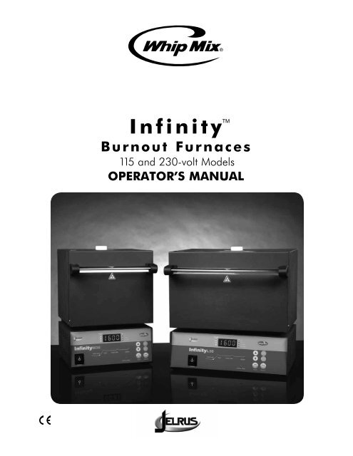
INTRODUCTIONThank you for purchasing an <strong>Infinity</strong> Burnout Furnace.We have designed and manufactured this furnace using the latest in microcomputer technology to give you many yearsof dependable service. The controls on your new <strong>Infinity</strong> are different from those you may be used to on an ordinaryburnout furnace. To ensure that your <strong>Infinity</strong> Burnout Furnace gives you the highest level of service, review and followthe guidelines outlined in this Operator’s <strong>Manual</strong>.WARRANTYThis <strong>Whip</strong> <strong>Mix</strong> equipment is warranted to be free from defects in material and workmanship from the date of installationfor a period of 24 months.Any item returned to our factory through an authorized dealer, will be repaired or replaced at our option at no chargeprovided that our inspection shall indicate it to have been defective. Dealer charges are not covered by this warranty.This warranty does not apply to damage due to shipping, misuse, careless handling or repairs by other than authorizedservice personnel. <strong>Whip</strong> <strong>Mix</strong> is not liable for indirect or consequential damage or loss of any nature in connection withthis equipment.This warranty is in lieu of all other warranties expressed or implied. No representative or person is authorized to assumefor us any liability in connection with the sale of our equipment.SAFETY INSTRUCTIONSUse of the <strong>Infinity</strong> furnace not in conformance with the instructions specified in this manual may result inpremature failure of the unit.WARNING: To prevent fire or electrical shock, do not expose this appliance to rain or moisture.ATTENTION USERS:This symbol alerts the user that importantOperating and Maintenance instructionshave been included with the unit. Readcarefully to avoid any problems.This symbol warns the user to usecaution surface is hot.Do Not Attempt Internal ServiceThe interior of the Main Assembly is only accessible by removing hardware with tools and should only be openedand serviced by qualified technicians. Since the interior of the unit may contain high voltage and dangerouscomponents, failure to heed this warning may result in equipment damage, personal injury and/or death.Please call <strong>Whip</strong> <strong>Mix</strong> between 8:00 a.m. and 5:00 p.m. (EST) for service information toll free 800-626-5651.2
SPECIFICATIONSINFINITY MElectrical 115V 50/60Hz 1075W230V 50/60Hz 1280WINFINITY L115V 50/60Hz 1392W230V 50/60Hz 1890WCapacity 8–1 3/4” rings or 2–3” rings 15–1 3/4” rings or5–1 3/4” rings and 3–3” ringOverallDimensionsHeatingChamberDimensionsINFINITY M AND LNumber of Programs 30NIGHT TIME(DELAY START)10.7”W x 10.2”D x 15.0”H(27.2cm x 26.9cm x 38.1cm)5-1/2”W x 5-1/4”D x 5-1/8”H(14.0cm x 13.3cm x 13.0cm)14.4”W x 11.0”D x 15.0”H(36.6cm x 28.0cm x 38.1cm)9-1/8”W x 5-1/4”D x 5-1/8”H(23.2cm x 13.3cm x 13.0cm)0 – 99 hoursNote: This is the time required for the program to be completedand ready to cast.HEAT RATE *(Stage 1)HEAT RATE *(Stages 2, 3, & 4)a) 1 – 30°F/min. (1 – 17°C/min.)b) “FULL” Stage heats at the maximum rate attainable.a) 1 – 30°F/min. (1 – 17°C/min.)b) “FULL” Stage heats at the maximum rate attainable.c) “NO” Stage is not used.d) “COOL” Stage cools down to the programmed temperature.Note: If “NO” is selected for a stage, that stage and all subsequentstages will not be used. The furnace, therefore, can be used for one,two, three or four stage operation.TEMPERATURE a) Stage 1: 150°F – 2012°F (66°C – 1100°C)b) Stage 2, 3, 4: 100°F – 2012°F (38°C – 1100°C)HOLD TIME0 – 4 hours* Programmable heat rates. Actual heat rate at high temperatures may be lower depending uponfurnace load and electrical voltage.ENVIRONMENTAL CONDITIONS• Indoor use• Altitude up to 2000 m• Temperature 5°C to 40°C (41°F to 104°F)• Maximum relative humidity 80% for temperatures up to 31°C (88°F) decreasing linearlyto 50% relative humidity at 40°C (104°F)• Mains supply voltage fluctuations not to exceed +/– 10% of the nominal voltage• Pollution Degree 2, Installation Category II• Protection Degree IP20 – protected against objects greater than 12.5mm, no liquid protection3
KEY PARTS IDENTIFICATION AND EXPLANATIONFRONT PANEL (Figure 1)DISPLAYDESCRIPTION1. Night Time Press to start a delayed program. The number entered is the time(DELAY START)required for the program to be COMPLETED AND READY TO CAST.When a program is running, press to display the time remaining tocomplete the program.2. Start / Stop Press to start or stop a program.3. Press to increase a number. The longer the button is pressed,the faster the numbers change.4. Press to decrease a number. The longer the button is pressed,the faster the numbers change.5. Enter / Review When programming or reviewing a program in process, pressto advance to the next parameter.6. Program select Press to select a program or to review the program currently running.7. STAGE 1–2–3–4 While programming, the number of active stages are illuminated.In the burnout process, the current STAGE flashes.8. °F and °C Identifies the temperature scale.9. °/ MIN Identifies the heat rate.10. HH : MM Indicates time. When flashing it indicates that a power failurehas occurred.11. Main Display A. The 4 digit display indicates the chamber temperature.B. When programming or reviewing, indicates PROGRAM NUMBER,NIGHT TIME (DELAY START) (time to completion), HEAT RATE,TEMP and HOLD TIME.C. Displays special words and error codes.12. Program Status Graph Indicates status of the burnout process.13. Door Interlock Shuts off electrical power from the heating platesSafety Switchwhen the furnace door is opened.4
PROGRAMkey parts identification and explanationVentTubeKeep clear 6” zonearound Vent TubeHeatingChamber111378FrontPanelM30STAGE1234°F°C°/MINHH:MMHEAT RATE TEMP HOLD TIME READYTIMEENTERREVIEWSELECTSTART95610SETSTOPPOWERNIGHT TIMENIGHTINSTANT312412Figure 1INFINITY M AND L IDENTIFICATION5
key parts identification and explanationLOWER BACK PANEL (Figure 2)DISPLAYDESCRIPTION1. Power Cord AC power cords are provided to correspond to receptacles that areavailable in a specific country.2. Circuit Breaker Protects circuitry from electrical overload.• Black button will “pop out” if overload is present.• To reset, wait one minute and push black button into body of circuit breaker.Figure 2INFINITY LOWER BACK PANEL (Medium)2IEC RECEPTACLEINFINITY LOWER BACK PANEL (Large)26IEC RECEPTACLE
installationunpack and set–up1. Unpack the contents of the box. Remove the following materials:A. Vent Tube – Remove from bubble wrap and insert in hole on top of furnace.B. Calibration Table Kit – Remove plastic bag containing two tablets and save for future use.C. Burnout Tray – Remove tray(s) from bubble wrap and install on the floor of the chamber.2. Place the furnace in position allowing a minimum of 10 inches (25.4 cm) of air space on all sides.Do not place the unit so as to block access to the power outlet.3. Plug the power cord into a grounded AC electrical outlet. First connect the power cord locatedin the rear of the furnace. A dedicated circuit is required.4. The furnace is now ready for operation.CAUTIONS:DO NOT BLOCK VENT HOLE ON TOP OF THE FURNACE. Hot gases are vented throughthis hole.TO SET TEMPERATURE SCALE (Figure 1)115V furnaces are pre-set in degrees Fahrenheit.230V furnaces are pre-set in degrees Celsius.1. Turn the power switch on. (If the furnace is already on, be sure it is in the idle mode – no programis running.) The chamber temperature appears on the Main Display and the °F light goes on.2. Press at the same time. The degree light switches to the opposite temperature scale.VENTING INSTRUCTIONSVent fans must have a minimum capacity of 100 cubic feet per minute for each burn out furnace.If a common hood is used for more than one burn out furnace, fan capacity must be 100 cubic feet per minutefor each square foot of hood opening.All hoods, vent pipe and ducting components must be constructed of non-combustable materials andbe installed in accordance with local building codes.Maximum expected exhaust temperature is 1800°F (980°C).Maximum expected exhaust waste heat is 5,100 BTU’S / Hour or 1,000 Watts.7
installationto turn the “beep” on and off (Figure 1)When a program is completed, 20 "beeps" sound every 15 minutes to remind the operatorthat the material is ready to cast.1. Be sure the <strong>Infinity</strong> is in the idle mode – no program us running.2. Press and (while holding) press PROGRAM SELECT to display the status of the "beep.""ON" indicates the beep is active. "OFF" indicates the beep is inactive.3. Use either of the to turn the "beeps" on or off.4. To return to the idle mode, wait 7 seconds or press STOP / START twice.(If STOP / START is pressed once, cycle starts.)8
operationprogram and operate – TWO stage program (Figure 1)1. Follow One Stage Program, Steps 1 – 6.2. Press ENTER / REVIEW. STAGE 1 light turns off, STAGE 2 and HEAT RATE lights turn on.Main Display shows four heat rate choices. Choose one:A. Select heat rate between 1°F – 30°F / min (1°C – 17°C / min) using .B. Select "FULL" to program maximum heat rate.C. Select "COOL" to program the furnace to cool to a selected temperature.D. Select "NO" to turn off STAGE 2, 3 and 4. This will result in a One Stage Program.NOTE: The HEAT RATE cannot be programmed to "COOL" in STAGE 1 – only in STAGE 2, 3 or 4.3. Press ENTER / REVIEW. HEAT RATE light turns off and TEMP light turns on. Enter for the temperaturerequired: heating temperature up to a maximum of 2012°F (1100°C) or cooling temperature downto a minimum of 100°F (38°C).4. Press ENTER / REVIEW. TEMP light turns off and HOLD TIME light turns on. Enter to programthe time needed to hold at the above temperature (0 – 4hrs.).5. For two stages, the furnace must be programmed not to use STAGE 3 or 4. Follow these steps:A. After completing Step 4, press ENTER / REVIEW. STAGE 2 light turns off, STAGE 3 andHEAT RATE lights turn on.B. Press Main Display shows “....5,4,3,2,1, COOL, NO.” Select “NO” to programthe furnace not to use STAGE 3 or 4.6. All necessary information for this program is now entered.7. To run the program immediately, press START / STOP.8. To delay the start of the program to be ready to cast at the pre–set time(see One Stage Program, Step 3), press NIGHT / TIME SET (DELAY START).NOTE: If NIGHT / TIME SET (DELAY START) is pressed while a program is running,the time remaining for completion of the program will appear on theMain Display for 5 seconds.10
operationprogram and operate – three stage program (Figure 1)1. Follow Two Stage Program, Steps 1 – 4.2. Press ENTER / REVIEW. STAGE 2 light turns off, STAGE 3 and HEAT RATE lights turn on.Main Display shows four heat rate choices. Choose one:A. Select heat rate between 1°F – 30°F /min (1°C – 17°C /min) using .B. Select "FULL" to program maximum heat rate.C. Select "COOL" to program the furnace to cool to a selected temperature.D. Select "NO" to turn off STAGE 3 and 4. This will result in a Two Stage Program.NOTE: The HEAT RATE cannot be programmed to "COOL" in STAGE 1 – only inSTAGE 2, 3 or 4.3. Press ENTER / REVIEW. HEAT RATE light turns off and TEMP light turns on. Enter forthe temperature required: heating temperature up to a maximum of 2012°F (1100°C) orcooling temperature down to a minimum of 100°F (38°C).4. Press ENTER / REVIEW. TEMP light turns off and HOLD TIME light turns on. Enter to programthe time needed to hold at the above temperature (0 – 4hrs.).5. For three stages, the furnace must be programmed not to use STAGE 4. Follow these steps:A. After completing Step 4, press ENTER / REVIEW. STAGE 3 light turns off,STAGE 4 and HEAT RATE lights turn on.B. Press Main Display shows “....5,4,3,2,1, COOL, NO.”Select “NO” to program the furnace not to use STAGE 4.6. All necessary information for this program is now entered.7. To run the program immediately, press START / STOP.8. To delay the start of the program to be ready to cast at the pre-set time(see One Stage Program, Step 3), press NIGHT / TIME SET (DELAY START).NOTE: If NIGHT / TIME SET (DELAY START) is pressed while a program is running,the time remaining for completion of the program will appear on theMain Display for 5 seconds.11
operationprogram and operate – four stage program (Figure 1)1. Follow Three Stage Program, Steps 1 – 4.2. Press ENTER / REVIEW. STAGE 3 light turns off, STAGE 4 and HEAT RATE lights turn on.Main Display shows four heat rate choices. Choose one:A. Select heat rate between 1°F – 30°F/min (1°C – 17°C/min) using .B. Select “FULL” to program maximum heat rate.C. Select “COOL” to program the furnace to cool to a selected temperature.D. Select “NO” to turn off Stage 4. This will result in a Three Stage Program.NOTE: The HEAT RATE cannot be programmed to “COOL” in STAGE 1 –only in STAGE 2, 3 or 4.3. Press ENTER / REVIEW. HEAT RATE light turns off and TEMP light turns on. Enter forthe temperature required: heating temperature up to a maximum of 2012°F (1100°C) orcooling temperature down to a minimum of 100°F (38°C).4. Press ENTER / REVIEW. TEMP light turns off and HOLD TIME light turns on.Enter to program thetime needed to hold at the above temperature (0 – 4 hrs.).5. All necessary information for this program is now entered.6. To run the program immediately, press START / STOP.7. To delay the start of the program to be ready to cast at the pre–set time(see One Stage Program, Step 3 ), press NIGHT / TIME SET (DELAY START).NOTE: If NIGHT / TIME SET (DELAY START) is pressed while a program is running,the time remaining for completion of the program will appear on theMain Display for 5 seconds.12
OPERATIONreview a program (figure 1)1. Turn the power switch on.2. Press PROGRAM SELECT.3. Press to select the program number to be reviewed. The program number (P1 – P30)will appear on the Main Display.4. The number of stages in the program are indicated by the STAGE lights next to the Main Display.5. Press ENTER / REVIEW. NIGHT TIME (DELAY START) light turns on. The number of hours entered for theentire program to be completed and ready to cast appears on the Main Display. After 7 seconds, if noother button is pressed, NIGHT TIME (DELAY START) light turns off and the actual furnace temperatureappears on the Main Display.6. Press ENTER / REVIEW again. If 7 seconds has not elapsed, the HEAT RATE light turns on. If 7 secondshas already elapsed and the furnace temperature appears on the Main Display, press ENTER / REVIEWtwice. First the NIGHT TIME (DELAY START) light turns on and then the HEAT RATE light turns on. Whenthe HEAT RATE light is on, the programmed heat rate appears on the Main Display.NOTE: STAGE 1 light is now on.7. Press ENTER / REVIEW and TEMP light turns on. The programmed temperature (TEMP) for STAGE 1appears on the Main Display.8. Press ENTER / REVIEW and HOLD TIME light turns on. The programmed HOLD TIME for STAGE 1appears on the Main Display in HR : MIN.9. All of the information in STAGE 1 has now been entered. If ENTER / REVIEW is pressed again,STAGE 2 light turns on. Review STAGE 2 following the same procedure as above. Continue pressingENTER / REVIEW to review all of the individual parameters in STAGE 2, 3, or 4.NOTE: NIGHT / TIME SET (DELAY START) appears only at the very beginning of STAGE 1.13
OPERATIONedit while a program is running (figure 1)1. To identify which program is running, press PROGRAM SELECT.NOTE: The program number cannot be changed usingwhile the program is running.2. To determine the time remaining for the completion of the program, press NIGHT / TIME SET (DELAY START).The time remaining appears on the Main Display for 5 seconds.3. Any individual parameter can be increased or decreased during the actual runningof all 30 programs.NOTE: HEAT RATE cannot be changed to "NO" in the stage currently runningor in the stages already completed.4. To change a parameter while a program is running, press ENTER / REVIEW to advance to the desiredSTAGE and parameter (i.e. HEAT RATE, TEMP or HOLD TIME). Initially, STAGE 1 will appear.Any parameter can be increased or decreased by pressing or .5. Any program can be stopped or started by pressing the START / STOP button.6. If a program is edited while running and the HEAT RATE in STAGE 2, 3 or 4 is set to "COOL" but thecorresponding TEMP programmed is entered to heat to a higher temperature than the previous stage,the <strong>Infinity</strong> will try to heat with a 0°F / Min (0°C / Min) HEAT RATE. In this case, when NIGHT / TIME SET(DELAY START) is pressed, 99:99 (Hr : Min) flashes on the Main Display, indicating that theprogram cannot be completed.14
OPERATIONSample one stage program(To be completed and ready to cast in 24 hours)NIGHT TIMEDELAY STARTHEAT RATE TEMP HOLD TIMESTAGE 124:00 10°F (6°C) 1600°F (871°C) 1:00STAGE 2NO**STAGE 3NO**STAGE 4NO***Though any number may appear, the unit is deactivated when “NO” is selected for the HEAT RATE.NOTE: To turn off STAGE 2,3 and 4, select “NO” for the HEAT RATE in STAGE 2.Sample two stage program(To start immediately)HEAT RATE TEMP HOLD TIMESTAGE 1STAGE 210°F (6°C)20°F (11°C)600°F (316°C) 301600°F (871°C) 1:00STAGE 3NO**STAGE 4NO***Though any number may appear, the unit is deactivated when “NO” is selected for the HEAT RATE.NOTE: To turn off STAGE 3 & 4, select “NO” for the HEAT RATE in STAGE 3.To start immediately, press START / STOP.Follow the same programming procedures if a three or four stage program is desired.15
OPERATIONSample three stage program(Program with Cooling)HEAT RATE TEMP HOLD TIMESTAGE 1STAGE 210°F (6°C)20°F (11°C)600°F (316°C) 301600°F (871°C) 1:00STAGE 3NO**STAGE 4NO***Though any number may appear, the unit is deactivated when “NO” is selected for the HEAT RATE.To start immediately, press START / STOP.Follow the same programming procedures if a three or four stage program is desired.NOTE: When the temperature is set to a lower temperature than in the previous stage,the furnace ignores the programmed HEAT RATE (except for "NO") and automaticallycools to the pre-set temperature. The time required for the cooling stage isdetermined by the pre-set temperature. The lower the temperature,the more time needed to cool down.NOTE: Press NIGHT / TIME SET (DELAY START) to start an overnight burnout.See SAMPLE ON STAGE PROGRAM to program NIGHT TIME (DELAY START) time.16
ERROR CODESNOTE: “Beeps” occur when the Error Code appears on the Main Displayerrorcode DESCRIPTION PROBABLE CAUSEEr 1Er 2INVALID ENTRYERROR: STAGE,HEAT RATE andTEMP lights flashTABLETTEMPERATURECALIBRATIONERROROccurs when the HEAT RATE is set to COOL but the TEMP of that stage ishigher than the TEMP of the prior stage (should be heating). This will occurwhen a program is already running and a parameter was edited in process.Occurs when the temperature on the display is outside the allowable rangeat the time the user pressed the ENTER / REVIEW keys simultaneously to setthe <strong>Infinity</strong> calibration temperature to 1500°F. If this occurs and is not anoperator error, it indicates that there is a problem with the thermocouple orthe PC board. Press ENTER / REVIEW to turn off the error indication andcontinue with the program. Press START / STOP to end the program.Er 3ELECTRONICSMALFUNCTIONOccurs when PC board hardware malfunctions.Er 4OPENTHERMOCOUPLEOccurs if the thermocouple is open or the connecting wire(s) are broken ordisconnected from the terminal board.Er 5REVERSEDTHERMOCOUPLEORNO HEATOccurs if the thermocouple extension wires have been connected backwardsto the terminals on the printed circuit board. The error will be detected 5minutes after heating program started. This error will also occur if theprogram is started and the chamber door is kept open for 5 minutes or therelay is defective, the heater plates are defective or there is a problem withthe main PC board.17
ERROR CODESerrorcode DESCRIPTION PROBABLE CAUSEEr 6Er 7SHORTEDTHERMOCOUPLE ORDEFECTIVE HEATERPLATESTHERMALRUNAWAYOccurs if the thermocouple wires are shorted or the heater plates aredefective causing <strong>Infinity</strong> to achieve a HEAT RATE of less than 6% of themaximum attainable HEAT RATE with full power applied to the heaterplates for 5 minutes. This error will also occur if a program is runningand the door is kept open for more than 5 minutes or the relay or theMain PC board developed a problem during a burnout process.Occurs when the temperature has exceeded 2015°F (1102°C) for 1minute if the highest temperature programmed was less than 2000°F(1093°C). This also occurs when the temperature has exceeded 2050°F(1121°C) for 1 minute if the highest temperature programmed was2000°F (1093°C) or higher.Flashing99:99 whenNIGHT / TIMESET (DELAYSTART) ispressedduring aprograminvalid entryerror while aprogram isrunningOccurs when the HEAT RATE in STAGE 2, 3 or 4 is set to “COOL” butthe corresponding TEMP is entered to heat to a higher temperaturethan the previous stage.18
SERVICECLEANING INSTRUCTIONSClean exterior of furnace only by wiping unit with a damp cloth coated with a mild non abrasive cleaner.CAUTION: The INFINITY should be serviced only by qualified service technicians. Be sureto unplug the power cord and wait for the furnace to cool before performing any serviceoperation. For help with operating or servicing your <strong>Whip</strong> <strong>Mix</strong> equipment, please call<strong>Whip</strong> <strong>Mix</strong> any time between 8:00am and 5:00pm Eastern time.Toll Free 1–800–626–5651Local 1–502–637–1451FAX 1–502–634–4512TEMPERATURE CALIBRATION<strong>Infinity</strong> Multi–Stage Burnout Furnaces come complete with temperature Calibration Tablets (2)which accurately melt at 1500°F (816°C). (Re–Order Calibration Tablet Kit – PN 15291).Your <strong>Infinity</strong> is factory calibrated. It is not necessary to re-calibrate on installation. If it becomesnecessary to re-calibrate in the future, use the following calibration procedure.Temperature Calibration with Calibration Tablets (Figure 3)1. Place a short metal casting ring towards the front center of the chamber.2. Place a ceramic tray or a small piece of casting ring lining material on top of the ring.Place a tablet in the center of the tray.3. Program the <strong>Infinity</strong> as follows:HEAT RATE TEMP HOLD TIMESTAGE 1 FULL 1200°F (649°C) 0:05STAGE 2 25°F (14°C) 1700°F (927°C) 0:00STAGE 3 NO * *STAGE 4 NO * **Though any number may appear, the unit is deativated when “NO” is selected for HEAT RATE.4. Close the furnace door and press START / STOP.5. When the furnace temperature attains 1400°F (760°C) as indicated on the Main display, open thefurnace door slightly and begin to check for the melting of the tablet. Continue to do this at each25°F (14°C) interval, opening the furnace door just enough to determine at a quick glance if thetablet has begun to liquefy at the edges.19
SERVICE6. When the tablet begins to melt or liquify at the edges, immediately press and hold.Then press ENTER/REVIEW. Your <strong>Infinity</strong> is now calibrated. Three “beeps” sound and“CAL” appears on the main display.POWER FAILURE1. If a power failure occurs, the <strong>Infinity</strong> memorizes the conditions prior to the loss of power.When the power returns, the <strong>Infinity</strong> returns to the proper point in the program.2. When power is returned, the HR:MIN light flashes indicating that a power failure has occurred.It continues to flash until START / STOP is pressed.NOTE: The HR:MIN light flashes if the power switch is turned off and on whilea program is running and START / STOP was not pressed. It will not flashif the power switch was turned off or a power failure occurred when thePROGRAM READY light was on.REPLACEMENT OF DOOR INSULATION AND SPRINGS1. Open, locate and remove the two screws on the door closest to the door hinges whichhold the retainer strip in place. Remove the retainer strip.2. Remove the one piece door insulation by sliding it toward the rear of the furnace and slightly lifting.3. To replace the springs, remove each spring from the hook which holds it in place.Remove both the hook and spring.4. To reinstall the new door insulation or springs and hooks, reverse the above procedure. If installingsprings and hooks, add grease to junction of spring and hook and spring and hinge junction.20
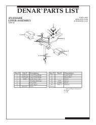
FIELD SERVICEREPLACEMENT OF HEATING PLATESTurn off the power to the oven, unplug the power cord,remove trays from the muffle chamber and insure thatthe oven is cool.Remove the upper back cover.On the rear of the unit remove the nuts that hold theheater plate wires to the ceramic terminals. Removeall hardware and wires from the terminals. Discardany burnt hardware and replace with hardware piecesshipped with the heater plates. Retain hardware forlater use. Straighten the wires for smoother removalof the plates.Straighten thermocouple at the bend and removebushings from heater plate wires.Move heater wires and thermocouple out of the upperhousing to allow insulation to slide out the back of theunit.From the front of the muffle chamber with the door openpush the entire insulation chamber out the back of unitand place on a table.Remove ceramic front plates from muffle insulation andplace aside.Place the new plates in the chamber, if back plates arebeing replaced as well they must be installed first, alsoinsure that the wires are bent up so they will slide intothe back.If the back plates are being replaced the filler stripshould be replaced as well. A new strip was shipped withthe plates.Side HeatingPlate Assembly(2)Insulating StripCeramic Insulating BushingsRear HeatingPlate LeadsOnce the plates are installed place the insulation chamberback inside the oven and wire the terminals according tothe model and voltage in the pictures on the next page:When wiring the plates insure that between each wirea flat washer is placed. See picture below.Flat WasherRear HeatingPlate LeadsCeramic FrontsHeater JumperNutLock WasherFrom here the plates can be removed by pulling themout the front of the insulation. The Large models haveback plates and side plates, while the Medium modelhas only side plates.Flat WasherNutLock WasherNote: Place flat washer between each wire.After the heater plates are wired, replace the upper backcover and bottom cover. Insure that the oven heats byrunning a program.21
Figure 4INFINITY WITH UPPER REAR PANEL REMOVEDJumperHeating Plate WirePower TerminalRear Insulating PanelThermocoupleCeramic InsulatingBushingHeater (Power) LeadsINFINITY- M30 115VJumperRear Insulating PanelHeating Plate WirePower TerminalThermocoupleCeramic InsulatingBushingHeater (Power) LeadsINFINITY- L30 115VHeating Plate WireRear Insulating PanelPower TerminalThermocoupleCeramic InsulatingBushingHeater (Power) LeadsINFINITY- L30 230V22
FIELD SERVICEREPLACEMENT OF THE MAIN PC BOARDPart numbers can be found on last page(s) of <strong>Manual</strong>.1. Remove the bottom panel.2. Note and record the color and location of each wire on the thermocoupleterminals located on the Main PC Board. Remove both wires.3. Tag or label the electrical connectors on the Main PC Board before removalso that you know where to reconnect each one. Create a sketch showing thelocations and referencing the tag or labeling. Pull straight out on the connector.DO NOT PULL ON THE WIRES.4. Remove the nuts and lock washers that hold the Main PC Board to the front panel and liftstraight away from the front panel to remove board.5. Align the holes in the new board with the standoffs on the front panel, reinstall the fastenersand screws.6. Reconnect the electrical connectors by referring to the tags and your sketch.7. Reconnect the two thermocouple wires to the thermocouple terminals observing the color codingnoted in Step 2. If thermocouple wires are reversed, 5 minutes after heating program is started,"Er 5" will appear on the Main Display.8. Replace the bottom panel.23
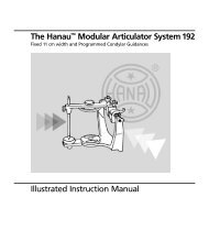
Figure 5INFINITY WIRING DIAGRAM24
FIELD SERVICEREPLACEMENT INSTRUCTIONS: 15295 JELRUS THERMOCOUPLEFor assistance call 1-800-626-5651 or write to: tops@whipmix.comCAUTION!TO PREVENT INJURY, ALWAYS TURN POWER OFF AND DISCONNECT THE OVEN’S POWERCORD BEFORE PERFORMING SERVICE. VERIFY THAT UNIT IS COOL TO THE TOUCH.Front View LargeRear View MediumRear View Large10Screws4 Screws Bottom Cover6 Screws Bottom CoverUnplug oven, remove trays from inside, then lay oven on its side and remove screws from bottom and back covers.Rear Back View MediumRear Back View LargeNote: make sure to run thermocouple wire through loopto hold wire stable before pulling into upper housing.Disconnect heater wires to pull thermocouple out from the muffle, then through the grommet into lower housing.Disconnect thermocouple from the main board.Note: Thermocouple should be wired as shown above. Heater wire must rest over ceramicsheath not to come in contact with bare wire or fiber sleeve.25
FIELD SERVICEREPLACEMENT OF THE SSR (Solid State Relay) (PN 96225)1. Remove the lower bottom panel (Figure 2, Page 6).2. Note and record the color and location of each of the four wires on the SSR terminals (Figure 5,Page 24). Remove each of the four wires by pulling straight up on the connecter. DO NOT PULLON THE WIRES.3. Remove the two nuts and screws that hold SSR in place. Lift SSR off the chassis (Figure 5, Page 24).4. Put the new SSR in place on the rear panel. Locate the SSR so that the center terminal will facedownward when the bottom panel is in place.5. Replace the four wires on the SSR (Figure 5, Page 24).6. Replace the lower bottom panel (Figure 2, Page 6).26
SPARE PARTS LISTSPARE PARTS FOR INFINITY M–30Part No.Description 115V 230VPower Cord Kit-Japan & U.S. 26202 26202NEW-Main PC Board 15303 15304Heater Jumper 33130 33130Ceramic Front Section 15292 15292Door Assembly 15284 15284Door Insulation 15722 15722Heating Plates Assembly Side (Set of 2) 33915 33916Ceramic Terminal Block w/Terminals 33935 33935Door Handle Kit 15279 15279NEW-Thermocouple Assembly Kit 15295 15295NEW-Solid State Relay (SSR) 25 amp 96225 96225Tray for Heating Chamber 33256 33256Power Switch 15684 15684Calibration Table Kit 1500°F (816°C) 15291 15291NEW-Door Switch Kit 15294 15294Vent Tube 15729 15729Ceramic Insulating Bushings (Pkg. of 4) 33958 33958NEW-Rubber Feet (Set of 4) 96011 96011Door Spring Hook Assembly Kit 33997 33997Door Hinges (Set of 2) 33998 33998Circuit Breaker 117046 117047Heater wire assembly 15312 1531227
SPARE PARTS LISTSPARE PARTS FOR INFINITY L–30Part No.Description 115V 230VNEW-Main PC Board 15305 15306Heater Jumper 33130 33130Ceramic Front Section (Set of 2) 15293 15293Door Assembly 15286 15286Door Insulation 15712 15712Heating Plate Assembly, Side (Set of 2) 15297 27957Heating Plate Assembly, Rear (Set of 2) 15296 27956Ceramic Terminal Block w/ Terminals 33936 33936Floor Plate w/ Filler Strip Insulation Kit 33981 33981Door Handle Kit 15286 15286NEW-Thermocouple Assembly Kit 15295 15295NEW-Solid State Relay (SSR) 25 amp 96225 96225Tray for Heating Chamber 33256 33256Power Switch 15684 15684Calibration Tablet Kit 1500°F (816°C) 15291 15291NEW-Door Switch Kit 15294 15294Vent Tube 15729 15729Ceramic Insulating Bushings (Pkg. of 4) 33958 33958NEW-Rubber Feet (Set of 4) 96011 96011Door Spring Hook Assembly Kit 33997 33997Door Hinges (Set of 2) 33998 33998Circuit Breaker 117046 117047Heater wire assembly 15312 1531228
PROGRAM CARD FORMSProgram #Metal(s)Program #Metal(s)HEAT TEMP HOLDRATETIMEHEAT TEMP HOLDRATETIMESTAGE 1STAGE 1STAGE 2STAGE 2STAGE 3STAGE 3STAGE 4STAGE 4Program #Metal(s)Program #Metal(s)HEAT TEMP HOLDRATETIMEHEAT TEMP HOLDRATETIMESTAGE 1STAGE 1STAGE 2STAGE 2STAGE 3STAGE 3STAGE 4STAGE 4Program #Metal(s)Program #Metal(s)HEAT TEMP HOLDRATETIMEHEAT TEMP HOLDRATETIMESTAGE 1STAGE 1STAGE 2STAGE 2STAGE 3STAGE 3STAGE 4STAGE 4Program #Metal(s)Program #Metal(s)HEAT TEMP HOLDRATETIMEHEAT TEMP HOLDRATETIMESTAGE 1STAGE 1STAGE 2STAGE 2STAGE 3STAGE 3STAGE 4STAGE 429
PROGRAM CARD FORMSProgram #Metal(s)Program #Metal(s)HEAT TEMP HOLDRATETIMEHEAT TEMP HOLDRATETIMESTAGE 1STAGE 1STAGE 2STAGE 2STAGE 3STAGE 3STAGE 4STAGE 4Program #Metal(s)Program #Metal(s)HEAT TEMP HOLDRATETIMEHEAT TEMP HOLDRATETIMESTAGE 1STAGE 1STAGE 2STAGE 2STAGE 3STAGE 3STAGE 4STAGE 4Program #Metal(s)Program #Metal(s)HEAT TEMP HOLDRATETIMEHEAT TEMP HOLDRATETIMESTAGE 1STAGE 1STAGE 2STAGE 2STAGE 3STAGE 3STAGE 4STAGE 4Program #Metal(s)Program #Metal(s)HEAT TEMP HOLDRATETIMEHEAT TEMP HOLDRATETIMESTAGE 1STAGE 1STAGE 2STAGE 2STAGE 3STAGE 3STAGE 4STAGE 430
361 Farmington AveP O Box 17183Louisville, KY 40217United States1–800–626–56511–502–637–1451www.whipmix.com<strong>Infinity</strong> is a trademark of <strong>Whip</strong> <strong>Mix</strong> ®©2012 <strong>Whip</strong> <strong>Mix</strong> ® .IPL00088 10/12