High Efficiency 3.0 High Efficiency 3.6 - Donauer Solartechnik ...
High Efficiency 3.0 High Efficiency 3.6 - Donauer Solartechnik ...
High Efficiency 3.0 High Efficiency 3.6 - Donauer Solartechnik ...

You also want an ePaper? Increase the reach of your titles
YUMPU automatically turns print PDFs into web optimized ePapers that Google loves.
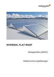
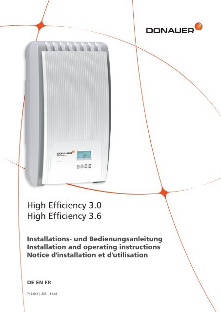
<strong>High</strong> <strong>Efficiency</strong> <strong>3.0</strong><br />
<strong>High</strong> <strong>Efficiency</strong> <strong>3.6</strong><br />
Installations- und Bedienungsanleitung<br />
Installation and operating instructions<br />
Notice d'installation et d'utilisation<br />
DE EN FR<br />
742.641 | Z03 | 11.43
Inhalt – Contents – Table des matières<br />
Deutsch 1<br />
English 37<br />
Français 73<br />
Zertifikate – Certificates – Certificats 109<br />
742.641 | 11.43
742.641 | 11.43<br />
Inhalt<br />
1 Vorwort 2<br />
2 Identifizierung 3<br />
3 Allgemeine Sicherheitshinweise 4<br />
4 Lieferumfang 5<br />
5 Bestimmungsgemäße Verwendung 5<br />
6 Zu dieser Anleitung 6<br />
6.1 Inhalt 6<br />
6.2 Zielgruppe 6<br />
6.3 Kennzeichnungen 6<br />
7 Aufbau und Funktion 7<br />
7.1 Gehäuse 7<br />
7.2 Bedientasten 8<br />
7.3 Display 8<br />
7.4 Kühlung 13<br />
7.5 Netzüberwachung 13<br />
7.6 Datenkommunikation 13<br />
8 Installation 16<br />
8.1 Sicherheitsmaßnahmen bei der Installation 16<br />
8.2 Wechselrichter montieren 17<br />
8.3 AC-Anschluss vorbereiten 18<br />
8.4 DC-Anschlüsse vorbereiten 19<br />
8.5 Datenverbindungskabel vorbereiten 19<br />
8.6 Wechselrichter anschließen und AC einschalten 19<br />
8.7 Erste Inbetriebnahme des Wechselrichters 20<br />
8.8 DC einschalten 22<br />
8.9 Demontage 23<br />
9 Bedienung 24<br />
9.1 Übersicht Bedienfunktionen 24<br />
9.2 Allgemeine Bedienfunktionen 25<br />
9.3 Wichtige Bedienfunktionen 25<br />
10 Selbsttest 27<br />
11 Störungsbeseitigung 29<br />
12 Wartung 31<br />
13 Entsorgung 31<br />
14 Technische Daten 32<br />
14.1 Wechselrichter 32<br />
14.2 AC-Leitung und Leitungsschutzschalter 34<br />
14.3 Ländertabelle 34<br />
15 Haftungsausschluss 35<br />
16 Gewährleistungs- und Garantiebestimmungen 35<br />
17 Kontakt 36<br />
18 Notizen 36<br />
DE<br />
1
DE<br />
1 Vorwort<br />
Vielen Dank, dass Sie sich für Wechselrichter der <strong>High</strong> <strong>Efficiency</strong> Series von <strong>Donauer</strong> <strong>Solartechnik</strong><br />
entschieden haben. Sie leisten durch die Nutzung der Sonnenenergie einen wesentlichen Beitrag<br />
zum Umweltschutz, indem die Belastung der Erdatmosphäre durch Kohlendioxyd (CO 2 ) und andere<br />
schädliche Gase insgesamt verringert wird.<br />
Höchste Effizienz mit langer Lebensdauer<br />
Die innovative Wechselrichter-Topologie, die auf einem einstufigen, trafolosen Schaltkonzept basiert,<br />
wird erstmals im <strong>High</strong> <strong>Efficiency</strong> <strong>3.0</strong> und <strong>High</strong> <strong>Efficiency</strong> <strong>3.6</strong> integriert und erreicht höchste Wirkungsgrade.<br />
Mit dem <strong>High</strong> <strong>Efficiency</strong> <strong>3.0</strong> und <strong>High</strong> <strong>Efficiency</strong> <strong>3.6</strong> werden Spitzenwirkungsgrade von<br />
98,6 % erzielt. Sogar gemäß EU-Maßstäben liegen die Geräte deutlich über 98 %. Damit setzen der<br />
<strong>High</strong> <strong>Efficiency</strong> <strong>3.0</strong> und der <strong>High</strong> <strong>Efficiency</strong> <strong>3.6</strong> Maßstäbe im Bereich der Photovoltaik-Netzeinspeisung.<br />
Ein neues, einzigartiges Kühlkonzept im Inneren der Wechselrichter garantiert eine gleichmäßige<br />
Verteilung der Wärme und dadurch eine lange Lebensdauer.<br />
Design-Gehäuse und mühelose Montage<br />
Erstmalig kann durch den sehr hohen Wirkungsgrad ein Design-Gehäuse aus Kunststoff eingesetzt<br />
werden. Dies bietet viele Vorteile. Die Oberflächentemperatur des <strong>High</strong> <strong>Efficiency</strong> <strong>3.0</strong> und <strong>3.6</strong> bleibt<br />
insgesamt sehr niedrig. Zudem ergeben sich deutliche Vorzüge bei der Montage.<br />
Die Leichtgewichte <strong>High</strong> <strong>Efficiency</strong> <strong>3.0</strong> und <strong>3.6</strong> mit lediglich 9 kg können mühelos und sicher an<br />
der Wand montiert werden. Die mitgelieferte Wandhalterung und die praktischen Griffmulden für<br />
Rechts- und Linkshänder ermöglichen eine einfache und sehr komfortable Montage. Zudem sind alle<br />
Anschlüsse und der DC-Freischalter von außen zugänglich.<br />
Visualisierung und Zubehör<br />
Der <strong>High</strong> <strong>Efficiency</strong> <strong>3.0</strong> und <strong>High</strong> <strong>Efficiency</strong> <strong>3.6</strong> verfügen über ein grafisches Display, mit dem Energieertragswerte,<br />
aktuelle Leistungen und Betriebsparameter der Anlage visualisiert werden. Das innovative<br />
Menü bietet die Möglichkeit einer individuellen Selektion der unterschiedlichen Messwerte.<br />
Weitere Informationen über Zubehör finden Sie unter www.donauer.eu. Selbstverständlich kann<br />
Ihnen auch Ihr Installateur nähere Auskunft über zur Verfügung stehende Optionen und Zubehör<br />
geben.<br />
2 742.641 | 11.43
2 Identifizierung<br />
742.641 | 11.43<br />
Allgemein<br />
Merkmal Beschreibung<br />
Typ <strong>High</strong> <strong>Efficiency</strong> <strong>3.0</strong> / <strong>High</strong> <strong>Efficiency</strong> <strong>3.6</strong><br />
Ausgabestand der Anleitung Z03<br />
Herstelleradresse Siehe Abschnitt 17, S. 36.<br />
Zertifikate Siehe S. 109 und www.donauer.eu<br />
Optionales Zubehör externer Datenlogger:<br />
• WEB‘log der Firma Meteocontrol<br />
• Solar-Log der Firma Solare Datensysteme<br />
Tab. 1: Identifizierungsmerkmale des Wechselrichters<br />
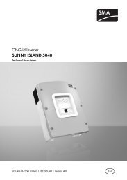
Typenschild<br />
4<br />
3<br />
2<br />
1<br />
DC Input:<br />
AC Output:<br />
Voltage: 350 - 800V<br />
Voltage: 230V, 50Hz<br />
MPP Voltage: 300 - 650V Current: max. 16A<br />
Current: max. 10A<br />
According to: VDE 0126-1-1<br />
Power: max. 3600W<br />
Overvoltage category: III<br />
VDE AR N 4105 IP classification: IP 21<br />
5<br />
Company:<br />
Art. number: 742.644<br />
Model: <strong>High</strong> <strong>Efficiency</strong> <strong>3.6</strong><br />
S/N:<br />
S/N:<br />
742644WJ001155550005<br />
742644WJ001155550005<br />
6<br />
Made in Germany<br />
Abb. 1: Typenschild (Beispiel)<br />
Die Position des Typenschilds ist in Abb. 4, S. 7 dargestellt.<br />
7<br />
8<br />
9<br />
� Seriennummer als Barcode und in Klarschrift<br />
� Norm zur Netzüberwachung<br />
� Technische Daten Eingang<br />
� Artikelnummer und Produktbezeichnung<br />
� <strong>Donauer</strong>-Logo<br />
� CE Zeichen<br />
� Herstellungsland<br />
� Technische Daten Ausgang<br />
� Schutzart<br />
Display (Information)<br />
Auf dem Display des Wechselrichters wird unter dem Menüeintrag Information/System information<br />
die zur aktuellen Software passende Version der Anleitung angezeigt.<br />
DE<br />
3
DE<br />
3 Allgemeine Sicherheitshinweise<br />
• Dieses Dokument ist Teil des Produkts.<br />
• Installieren und benutzen Sie das Gerät erst, nachdem Sie dieses Dokument gelesen und verstanden<br />
haben.<br />
• Führen Sie die in diesem Dokument beschriebenen Maßnahmen immer in der angegebenen Reihenfolge<br />
durch.<br />
• Bewahren Sie dieses Dokument während der Lebensdauer des Geräts auf. Geben Sie das Dokument<br />
an nachfolgende Besitzer und Benutzer weiter.<br />
• Durch unsachgemäße Bedienung kann der Ertrag des Solarsystems gemindert werden.<br />
• Mit beschädigtem Gehäuse darf das Gerät nicht an die DC- oder AC-Leitungen angeschlossen<br />
sein.<br />
• Gerät sofort außer Betrieb setzen und vom Netz und den Solarmodulen trennen, wenn eine der<br />
folgenden Komponenten beschädigt ist:<br />
– Gerät (keine Funktion, sichtbare Beschädigung, Rauchentwicklung, etc.)<br />
– Leitungen<br />
– Solarmodule<br />
Die Anlage darf nicht wieder eingeschaltet werden, bevor<br />
– das Gerät vom Händler oder Hersteller repariert wurde.<br />
– beschädigte Kabel oder Solarmodule von einer Fachkraft repariert wurden.<br />
• Kühlrippen niemals abdecken.<br />
• Gehäuse nicht öffnen! Lebensgefahr! Garantieanspruch verfällt!<br />
• Vom Werk angebrachte Schilder und Kennzeichnungen niemals verändern, entfernen oder unkenntlich<br />
machen.<br />
Sicherheitshinweis auf dem Gerät<br />
3 4<br />
2<br />
1<br />
Attention<br />
Présence de deux sources<br />
de tension<br />
- Réseau de distribution<br />
- Panneaux photovoltaïques<br />
Montage<br />
HV-Test<br />
Endtest<br />
10min<br />
Isoler les deux sources<br />
avant toute<br />
intervention<br />
5<br />
� Fertigungshinweise des Herstellers<br />
� Gefährliche Spannungen an den Bauteilen<br />
können bis zu 10 Min. nach Abschalten von<br />
DC-Freischalter und Leitungsschutzschalter<br />
anliegen.<br />
� Achtung. Es sind 2 Spannungsquellen vorhanden:<br />
Stromnetz, Solarmodule<br />
� Vor Arbeiten am Gerät beide Spannungsquellen<br />
vom Gerät trennen:<br />
Solarmodule mittels DC-Freischalter und<br />
Stromnetz mittels Leitungsschutzschalter<br />
� Anleitung beachten!<br />
4 742.641 | 11.43
4 Lieferumfang<br />
• <strong>High</strong> <strong>Efficiency</strong> <strong>3.0</strong>/<strong>3.6</strong> �<br />
• Wandhalterung �<br />
• AC-Stecker �<br />
• Installations- und Bedienungsanleitung �<br />
�<br />
Abb. 2: Lieferumfang<br />
5 Bestimmungsgemäße Verwendung<br />
742.641 | 11.43<br />
�<br />
�<br />
<strong>High</strong> <strong>Efficiency</strong> <strong>3.0</strong><br />
<strong>High</strong> <strong>Efficiency</strong> <strong>3.6</strong><br />
�<br />
Installations- und Bedienungsanleitung<br />
Installation and operating instructions<br />
Notice d'installation et d'utilisation<br />
Der Wechselrichter darf nur in netzgekoppelten Photovoltaikanlagen verwendet werden. Der Wechselrichter<br />
ist für alle Solarmodule geeignet, deren Anschlüsse nicht geerdet werden müssen.<br />
Potentialverlauf der Photovoltaikspannung U PV bei 350 V und 550 V<br />
320 V<br />
275 V<br />
175 V<br />
0 V<br />
-175 V<br />
U<br />
-275 V<br />
-320 V<br />
U PV = 350 V<br />
t<br />
U<br />
320 V<br />
275 V<br />
175 V<br />
0 V<br />
-175 V<br />
-275 V<br />
-320 V<br />
Abb. 3: Potentialverlauf der Photovoltaikspannung U PV bei 350 V (links) und 550 V (rechts);<br />
U PV = Potential zwischen Plus - und Minuspol am DC-Eingang<br />
DE EN FR<br />
742.641 | Z03 | 11.43<br />
U PV = 550 V<br />
t<br />
DE<br />
5
DE<br />
6 Zu dieser Anleitung<br />
6.1 Inhalt<br />
Diese Anleitung enthält alle Informationen, die eine Fachkraft zum Einrichten und Betreiben des<br />
Wechselrichters benötigt. Für die Montage weiterer Komponenten (z. B. Solarmodule, Verkabelung)<br />
die Anleitungen der jeweiligen Hersteller zu beachten.<br />
6.2 Zielgruppe<br />
Zielgruppe dieser Anleitung sind Fachkräfte und Anlagenbetreiber, soweit nicht anders gekennzeichnet.<br />
Fachkräfte sind Personen, welche<br />
• über die Kenntnis einschlägiger Begriffe und Fertigkeiten beim Einrichten und Betreiben von<br />
Solarsystemen verfügen.<br />
• aufgrund ihrer fachlichen Ausbildung, Kenntnisse und Erfahrungen sowie Kenntnis der einschlägigen<br />
Bestimmungen die folgenden Arbeiten beurteilen und mögliche Gefahren erkennen<br />
können:<br />
– Montieren von Elektrogeräten<br />
– Konfektionieren und Anschließen von Datenleitungen<br />
– Konfektionieren und Anschließen von Stromversorgungsleitungen<br />
6.3 Kennzeichnungen<br />
6.3.1 Symbole<br />
Tab. 2 beschreibt die in dieser Anleitung und auf dem Gerät verwendeten Symbole.<br />
Symbol Beschreibung Ort Symbol Beschreibung Ort<br />
allgemeiner Gefahrenhin- Anleitung Hinweis zur Bedienung des Anleitung<br />
weis<br />
Geräts oder zur Benutzung<br />
der Anleitung<br />
Gefahr durch Elektrizität Anleitung<br />
Vor Gebrauch des Pro- Gerät<br />
Gerät<br />
dukts Anleitung lesen.<br />
Tab. 2: Symbole in der Anleitung und auf dem Gerät<br />
6.3.2 Signalwörter<br />
Die in Tab. 3 beschriebenen Signalwörter werden immer in Verbindung mit einem der Symbole aus<br />
Tab. 2 verwendet.<br />
Signalwort Beschreibung<br />
Gefahr Tod oder schwere Körperverletzung<br />
Warnung leichte oder mittelschwere Körperverletzung<br />
Vorsicht Sachschaden<br />
Hinweis Hinweis zur Bedienung oder zur Benutzung der Anleitung<br />
Tab. 3: Signalwörter<br />
6.3.3 Kennzeichnungen im Text<br />
Kennzeichnung Beschreibung Kennzeichnung Beschreibung<br />
• Aufzählung √ Voraussetzung für eine Handlung<br />
– Unterpunkt einer Aufzählung kursiv Hervorhebung, leicht<br />
� einzelner Handlungsschritt fett Hervorhebung, stark<br />
1., 2., 3., ... mehrere Handlungsschritte in Courier Bezeichnung von Produktele-<br />
Folge<br />
menten wie Tasten, Anzeigen,<br />
Betriebszuständen.<br />
Tab. 4: Kennzeichnungen im Text<br />
6 742.641 | 11.43
6.3.4 Abkürzungen<br />
Abkürzung Beschreibung<br />
ENS interne Netzüberwachung des Wechselrichters (deutsch: Einrichtung zur Netzüberwachung<br />
mit zugeordneten Schaltorganen).<br />
MPP Arbeitspunkt mit der höchsten Leistungsabgabe (engl.: maximum power point)<br />
SELV Schutzkleinspannung (englisch: Safety Extra Low Voltage)<br />
Tab. 5: Abkürzungen<br />
7 Aufbau und Funktion<br />
7.1 Gehäuse<br />
3<br />
742.641 | 11.43<br />
9 18 7 16 15<br />
10<br />
1<br />
2<br />
14<br />
1 Haube<br />
2 Display (monochrom, 128 x 64 Pixel)<br />
13 Typenschild, Warnhinweise<br />
14 Bedientasten: ESC, �, �, SET (von links nach rechts)<br />
15 1x AC-Anschluss<br />
16 2x RJ45-Buchsen (RS485-Schnittstelle)<br />
7 1x DC-Anschluss Minus (–) für Solarmodule (Multi-<br />
Contact DC Buchse MC4, berührungssicher)<br />
8 1x DC-Anschluss Plus (+) für Solarmodule (Multi-Contact<br />
DC Buchse MC4, berührungssicher)<br />
19 DC-Freischalter (trennt Plus- und Minuseingang gleich-<br />
zeitig)<br />
10 1 Terminierung (Schiebeschalter):<br />
On: Terminierung eingeschaltet (Schiebeschalter rechts)<br />
Off: Terminierung ausgeschaltet (Schiebeschalter links)<br />
Siehe auch Detail-Zeichnung unten.<br />
Off On<br />
Abb. 4: Komponenten an Vorder- und Unterseite des Gehäuses<br />
Die einzelnen Gehäusekomponenten sind nachstehend ausführlich beschrieben.<br />
10<br />
6<br />
6<br />
DE<br />
7
DE<br />
7.2 Bedientasten<br />
7.3 Display<br />
Die Bedientasten (� in Abb. 4) haben folgende Funktionen:<br />
Taste Aktion Funktion (abhängig vom jeweiligen Display-Inhalt)<br />
ESC kurz drücken • springt eine Menüebene höher<br />
• verwirft eine Änderung<br />
lange drücken<br />
(≥ 1 Sekunde)<br />
springt auf die Statusanzeige<br />
� kurz drücken • bewegt den Markierungsbalken 1 Position nach oben; nach dem obersten<br />
Eintrag folgt der unterste Eintrag<br />
• bewegt in einer numerischen Einstellung die Markierung 1 Position nach<br />
links<br />
• erhöht einen Einstellwert um 1 Stufe; nach dem höchsten Wert folgt der<br />
kleinste Wert<br />
� kurz drücken • bewegt den Markierungsbalken 1 Position nach unten; nach dem untersten<br />
Eintrag folgt der oberste Eintrag<br />
• bewegt in einer numerischen Einstellung die Markierung 1 Position nach<br />
rechts<br />
• verringert einen Einstellwert um 1 Stufe; nach dem kleinsten Wert folgt<br />
der höchste Wert<br />
SET kurz drücken • springt eine Menüebene tiefer<br />
• ein markierter Zahlenwert beginnt zu blinken und kann geändert werden<br />
• übernimmt eine Änderung<br />
• ändert den Zustand eines Steuerelements (Kontrollkästchen/Optionsfeld)<br />
lange drücken<br />
(≥ 1 Sekunde)<br />
beantwortet einen Dialog mit Ja<br />
Tab. 6: Funktionen der Bedientasten<br />
7.3.1 Allgemeines<br />
Für die Darstellung auf dem Display (� in Abb. 4) gilt allgemein:<br />
• Symbol : Wenn der Wechselrichter große Datenmengen verarbeitet, kann er in dieser Zeit<br />
keine Benutzereingaben bearbeiten. Die entstehende Wartezeit wird durch das animierte Sonnensymbol<br />
gekennzeichnet.<br />
• Sind nicht sichtbare Inhalte vorhanden, erscheint am rechten Display-Rand eine Bildlaufleiste mit<br />
Schiebebalken. Die Länge des Schiebebalkens zeigt den Umfang der nicht sichtbaren Inhalte an.<br />
• Markierte Einträge sind schwarz unterlegt, die Schrift ist weiß.<br />
• Die Hintergrundbeleuchtung wird 30 Sekunden nach dem letzten Tastendruck ausgeschaltet.<br />
• Störungen werden durch eine rot blinkende Hintergrundbeleuchtung angezeigt. Gleichzeitig wird<br />
eine Ereignismeldung eingeblendet.<br />
8 742.641 | 11.43
7.3.2 Informationen<br />
Die am Display angezeigten Informationen sind nachstehend anhand von Abbildungsbeispielen<br />
beschrieben.<br />
742.641 | 11.43<br />
Statusanzeige<br />
In der Statusanzeige werden Messwerte wie folgt einzeln angezeigt:<br />
Menü<br />
3 4<br />
2<br />
1<br />
5 6<br />
2<br />
1<br />
7<br />
� Messwertname<br />
� Messwert mit Einheit<br />
� aktuelles Datum<br />
� Symbol nicht quittierte Statusmeldungen; mehr dazu im<br />
Abschnitt 11, S. 29.<br />
� animiertes Symbol Connect mit 2-stelliger Wechselrichteradresse;<br />
zeigt Datenverkehr auf dem RS485-Bus an.<br />
� Symbol Derating<br />
� aktuelle Uhrzeit<br />
Für die Statusanzeige gilt:<br />
• Die Messwerte, die in der Statusanzeige erscheinen, werden<br />
unter Einstellungen/Messwerte festgelegt. Einige<br />
Messwerte erscheinen immer (Voreinstellung).<br />
• Die in der Statusanzeige angezeigte CO 2 -Einsparung<br />
wird anhand des Einsparfaktors 508 g/kWh errechnet.<br />
� Bezeichnung des Haupt-/Untermenüs<br />
� Menüeinträge<br />
Ertrag numerisch (Tage, Monate, Jahre)<br />
Tages-, Monats- und Jahreserträge können numerisch in einer Liste angezeigt werden.<br />
1<br />
2<br />
Ertrag numerisch (Gesamtertrag)<br />
Der Gesamtertrag wird in einem eigenen Fenster angezeigt.<br />
2<br />
1<br />
3<br />
� Ertragszeitraum (Tag/Monat/Jahr)<br />
� Einzelerträge mit Zeitraum und Wert (1 je Zeile)<br />
Die Ertragszeiträume enthalten die folgende Anzahl an Einzelerträgen:<br />
Tagesertrag: letzte 31 Tage 1)<br />
Monatsertrag: letzte 12 Monate 1)<br />
Jahresertrag: letzte 30 Jahre 1)<br />
1) Der Ertragswert wird mit 0 angezeigt, wenn der Wechselrichter<br />
zu diesem Zeitpunkt noch nicht installiert war.<br />
� Ertragszeitraum Gesamtertrag (alle Erträge seit der ersten<br />
Inbetriebnahme)<br />
� Startzeitpunkt der Aufzeichnungen<br />
� Gesamtertragswert mit Einheit<br />
DE<br />
9
DE<br />
Ertrag grafisch (Tage, Monate, Jahre)<br />
Tages-, Monats- und Jahreserträge können grafisch in einem Diagramm angezeigt werden.<br />
22<br />
1 4<br />
Ereignismeldungen<br />
Generatorkennlinie<br />
2 3<br />
Systeminformation<br />
1<br />
3<br />
1<br />
� Zeitraum eines Einzelertrags (hier: Tagesertrag)<br />
� y-Achse:<br />
– Ertrag in kWh<br />
– Mit Zusatz M: Ertrag in MWh<br />
– Skalierung ändert sich je nach Maximalwert<br />
� x-Achse: Zeit in Stunden/Tagen/Monaten/Jahren<br />
� Summe der im Diagramm angezeigten Einzelerträge in<br />
kWh<br />
In der grafischen Darstellung können die Jahreserträge der<br />
letzten 20 Jahre angezeigt werden.<br />
Siehe Abschnitt 11, S. 29.<br />
� x-Achse: Eingangsspannung in V<br />
� y-Achse: Leistung in kW<br />
� Scheitelpunkt = MPP<br />
Wird der Menüeintrag Generatorkennlinie aufgerufen, nimmt<br />
der Wechselrichter die Generatorkennlinie auf und zeigt sie<br />
anschließend an (Abb. links oben). Dabei gilt:<br />
• Beim Aufnehmen durchfährt der Wechselrichter den Eingangsspannungsbereich<br />
und zeichnet die sich ergebende<br />
Leistung auf. Dauer: wenige Sekunden, wird angezeigt.<br />
• Der MPP befindet sich am Scheitelpunkt der Generatorkennlinie.<br />
• Scheitelpunkt und Generatorkennlinie verändern sich mit<br />
der Sonneneinstrahlung.<br />
• Mehrere Scheitelpunkte deuten auf eine Teilverschattung<br />
hin (Abb. links unten).<br />
Der Menüeintrag Informationen enthält die folgenden 4<br />
Untermenüeinträge.<br />
• Kontaktdaten<br />
• Systeminformation (siehe Abb. links):<br />
– Produktbezeichnung<br />
– Seriennummer des Wechselrichters<br />
– Informationen zu Soft- und Hardware-Versionen des<br />
Wechselrichters (siehe Bsp. � in Abb. links)<br />
– eingestellte Wechselrichter-Adresse<br />
– Version der zum Wechselrichter gehörenden Anleitung<br />
• Länderparameter: eingestelltes Land und Parameter;<br />
siehe auch S. 34.<br />
• Selbsttest: Ergebnis des letzten erfolgreich durchgeführten<br />
Selbsttests (nur wenn eingestelltes Land Italien ist)<br />
10 742.641 | 11.43
7.3.3 Steuerelemente<br />
Die am Display angezeigten Steuerelemente zum Einstellen des Wechselrichters sind nachstehend<br />
anhand von Abbildungsbeispielen beschrieben.<br />
742.641 | 11.43<br />
Auswahlliste mit Kontrollkästchen<br />
2<br />
2<br />
2<br />
Auswahlliste mit Optionsfeldern<br />
2<br />
2<br />
2<br />
Dialoge (allgemein)<br />
1<br />
Numerische Einstellungen<br />
2<br />
3<br />
2<br />
1<br />
1<br />
2 22<br />
1<br />
3<br />
3<br />
� Bezeichnung der Auswahlliste<br />
� Kontrollkästchen mit Namen:<br />
– Kontrollkästchen ermöglichen Mehrfachauswahl<br />
– das markierte Kontrollkästchen ist schwarz unterlegt<br />
– voreingestellte Kontrollkästchen haben keinen Rahmen<br />
und sind immer eingeschaltet (Ändern nicht möglich)<br />
� Bildlaufleiste<br />
� Bezeichnung der Auswahlliste<br />
� Optionsfelder mit Namen:<br />
– Optionsfelder sind gegenseitig ablösend (nur 1 Optionsfeld<br />
kann eingeschaltet sein)<br />
– das markierte Optionsfeld ist schwarz unterlegt<br />
� Bildlaufleiste<br />
� Dialog-Überschrift<br />
� Frage an den Benutzer<br />
� Auswahlmöglichkeiten:<br />
Zurück (abbrechen): ESC drücken<br />
Bestätigen (Frage mit Ja beantworten): SET 1 Sekunde<br />
drücken<br />
� Bezeichnung der numerischen Einstellung<br />
� Einstellwerte; der markierte Einstellwert ist schwarz unterlegt.<br />
Für das numerische Einstellen von Vergütung und Datum gilt:<br />
Vergütung<br />
• mögliche Währungen: £ (Pfund), € (Euro), kr (Krone),<br />
keine.<br />
• Die einstellbare Höhe der Vergütung ist aus technischen<br />
Gründen begrenzt. Bei Bedarf muss die Vergütung in einer<br />
anderen Einheit eingegeben werden. Beispiel: Dollar statt<br />
Cent (Währung keine einstellen).<br />
Datum<br />
Beim Einstellen von Monat/Jahr wird überprüft, ob der eingestellte<br />
Tag zulässig ist. Wenn nicht, wird der Tag automatisch<br />
korrigiert.<br />
Beispiel: 31.02.2011 wird korrigiert zu 28.02.2011.<br />
DE<br />
11
DE<br />
7.3.4 Weitere wichtige Display-Inhalte<br />
Dialog Maximalwerte rücksetzen<br />
Auswahl Messwerte<br />
Akustischer Alarm<br />
Hintergrundbeleuchtung<br />
Mit dem Dialog Maximalwerte rücksetzen können die folgenden<br />
gespeicherten Maximalwerte auf 0 zurückgesetzt<br />
werden:<br />
• Tagesmaximalleistung<br />
• Tagesmaximalertrag<br />
• Absolute Maximalleistung<br />
Auswahl der Messwerte, die in der Statusanzeige angezeigt<br />
werden können. Folgende Messwerte können ausgewählt<br />
werden:<br />
• Ausgangsleistung: Ausgangsleistung des Wechselrichters<br />
1)<br />
• Akt. Tagesertrag: Tagesertrag von 0:00 bis jetzt.<br />
• PV-Spannung: von den Solarmodulen gelieferte Spannung<br />
• PV-Strom: von den Solarmodulen gelieferter Strom<br />
• Netzspannung 1)<br />
• Netzstrom: ins Netz eingespeister Strom<br />
• Netzfrequenz<br />
• Innentemperatur: Innentemperatur des Wechselrichters<br />
• Leistungsreduzierung (Derating): Ursache der Leistungsreduzierung<br />
• Tagesmaximalleistung: höchste Leistung des aktuellen<br />
Tages 2)<br />
• Abs. Maximalleistung: höchste eingespeiste Leistung<br />
2)<br />
• Tagesmaximalertrag: max. erreichter Tagesertrag 2)<br />
• Betriebsstunden: Betriebsstunden am Netz (einschließlich<br />
Nachtstunden)<br />
• Gesamtertrag: Ertrag seit Inbetriebnahme<br />
• CO 2 Einsparung: CO 2 -Einsparung seit Inbetriebnahme<br />
1) Messwert wird immer angezeigt (Ausschalten nicht möglich)<br />
2) auf 0 zurücksetzbar über Einstellungen/Max. Werte<br />
rücksetzen<br />
Ereignismeldungen werden durch einen akustischen Alarm<br />
signalisiert (ca. 4,5 kHz).<br />
• 2 Töne: Warnung<br />
• 3 Töne: Fehler<br />
• aus<br />
• automatisch: nach Tastendruck 30 Sekunden eingeschaltet<br />
• Einspeisebetrieb:<br />
– kein Einspeisen: nach Tastendruck 30 Sekunden eingeschaltet,<br />
danach ausgeschaltet<br />
– Einspeisen: nach Tastendruck 30 Sekunden eingeschaltet,<br />
danach gedimmt<br />
12 742.641 | 11.43
7.4 Kühlung<br />
Die interne Temperaturregelung verhindert überhöhte Betriebstemperaturen. Wenn die Innentemperatur<br />
des Wechselrichters die (Derating-)Grenze überschreitet, passt sich die Leistungsaufnahme aus<br />
den Solarmodulen automatisch an. Somit wird die Wärmeabgabe des Wechselrichters verringert und<br />
eine zu hohe Betriebstemperatur vermieden.<br />
Der Wechselrichter wird mit Kühlrippen an Vorder- und Rückseite durch Konvektion gekühlt. Innerhalb<br />
des abgeschlossenen Gehäuses verteilt ein wartungsfreier Ventilator die Abwärme gleichmäßig<br />
auf die Gehäuseoberfläche.<br />
7.5 Netzüberwachung<br />
Während des Einspeisens kontrolliert der Wechselrichter ständig die Netzparameter. Hält das Netz<br />
die gesetzlichen Vorgaben nicht ein, schaltet der Wechselrichter automatisch ab. Sind die gesetzlichen<br />
Vorgaben wieder erfüllt, schaltet der Wechselrichter automatisch ein.<br />
Die gesetzlichen Vorgaben für die Netzparameter finden Sie in der Ländertabelle, S. 34.<br />
7.6 Datenkommunikation<br />
7.6.1 Daten<br />
Der Wechselrichter zeigt folgende Daten an und speichert sie im dauerhaft internen Speicher<br />
(EEPROM).<br />
Anzeigen<br />
• Spannung und Strom des Solargenerators<br />
• Eingespeiste Leistung und Strom<br />
• Spannung und Frequenz des Stromnetzes<br />
• Energieerträge auf Tages-, Monats- und Jahresbasis<br />
• Fehlerzustände, Hinweise<br />
Einige der Daten können an die unter 7.6.2 genannten Geräte übertragen werden.<br />
Speichern (EEPROM)<br />
• Fehlerzustände, Hinweise<br />
• Energieerträge auf Tages-, Monats- und Jahresbasis (Tab. 7)<br />
Die Speichertiefe der Energieertragsdaten ist wie folgt:<br />
Energieertragsdaten Speichertiefe/Zeitraum<br />
10-Minuten-Werte 31 Tage<br />
Tageswerte 12 Monate<br />
Monatswerte 30 Jahre<br />
Jahreswerte 30 Jahre<br />
Gesamtertrag dauerhaft<br />
Tab. 7: Speichertiefe der Energieertragsdaten<br />
7.6.2 Schnittstellen und angeschlossene Geräte<br />
Der Wechselrichter kommuniziert über einen RS485-Bus mit anderen Geräten. Dabei gilt:<br />
• Der Wechselrichter hat zwei RS485-Schnittstellen (RJ45-Buchsen) an der Gehäuseunterseite.<br />
• Der RS485-Bus muss am Anfang und am Ende terminiert werden; siehe 7.6.4.<br />
• Als Bus-Kabel können RJ45-Standardkabel verwendet werden (Cat-5 Patch-Kabel, nicht mitgeliefert).<br />
Für lange Datenverbindungen alternatives Datenverbindungskabel verwenden; siehe 7.6.3.<br />
• Die über den RS485-Bus verbundenen Wechselrichter arbeiten als Slaves.<br />
• Ist ein optionales Gerät angeschlossen, so arbeitet dieses Gerät als Master.<br />
• Es darf nur 1 Master am RS485-Bus angeschlossen sein.<br />
742.641 | 11.43<br />
DE<br />
13
DE<br />
Folgende, optionale Geräte unterstützen das Übertragungsprotokoll des Wechselrichters:<br />
• PC oder Notebook (mit entsprechender Software, nur für Fachkräfte):<br />
– Firmware-Updates übertragen<br />
– Wechselrichter-Informationen mittels Service-Software auslesen<br />
– Anschluss an den Wechselrichter über optionalen Adapter RS485/USB möglich. Der Adapter ist<br />
bei <strong>Donauer</strong> erhältlich.<br />
• externe Datenlogger, von <strong>Donauer</strong> für eine professionelle Anlagenüberwachung empfohlen:<br />
– WEB‘log Comfort (Fa. Meteocontrol)<br />
– Solar-Log (Fa. Solare Datensysteme)<br />
Hinweis<br />
An den externen Datenloggern müssen vor dem Anschließen die Einstellungen gemäß den Herstellerangaben<br />
vorgenommen werden.<br />
Das Verkabelungsschema des RS485-Busses ist nachstehend dargestellt.<br />
1 2 3 4<br />
5 5 5<br />
RS485 RS485 RS485<br />
Abb. 5: Verkabelungsschema, dargestellt am Beispiel des WEB‘log Comfort<br />
� externer Datenlogger (hier: des WEB‘log Comfort)<br />
� erster Wechselrichter<br />
� Wechselrichter<br />
� letzter Wechselrichter, terminiert<br />
� RJ45-Standardkabel (Patch-Kabel)<br />
7.6.3 Alternatives Datenverbindungskabel<br />
Vorsicht<br />
Materialschäden durch elektrische Spannung! Das alternative Datenverbindungskabel darf nur von<br />
einer Fachkraft angefertigt werden.<br />
Das alternative Datenverbindungskabel ist ein Cat-5-Kabel für lange Datenverbindungen. Für das<br />
alternative Datenverbindungskabel gilt:<br />
• Die Gesamtlänge des RS485-Bus darf 1000 m nicht überschreiten (Master/erster Wechselrichter<br />
bis zum letzten Wechselrichter).<br />
• Steckerbelegung gemäß Tab. 8, S. 15 verwenden, wenn das alternative Datenverbindungskabel<br />
an die RJ45-Buchse des ersten Wechselrichters und an den externen Datenlogger (z. B. WEB‘log<br />
Comfort) angeschlossen wird.<br />
14 742.641 | 11.43
externe Datenlogger<br />
Gerät<br />
Stecker<br />
Wechselrichter<br />
RJ45<br />
Solar-Log<br />
Klemmleiste<br />
WEB‘log<br />
RJ12<br />
1)<br />
Signal<br />
�<br />
1 1 2 Data A<br />
2 4 4 Data B<br />
3 – – –<br />
Kontakt<br />
4<br />
5<br />
–<br />
–<br />
–<br />
–<br />
–<br />
–<br />
6 – – –<br />
7 – – –<br />
8 3 6 Ground<br />
Tab. 8: Steckerbelegung des alternativem Datenkabels<br />
1) Vorsicht<br />
Gefahr der Zerstörung des RS485-Eingangs des Wechselrichters.<br />
Kontakt 1 der RJ12-Buchse des Web‘log-Datenloggers führt 24 V DC. Das alternative Datenverbindungskabel<br />
niemals an Kontakt 1 anschließen!<br />
7.6.4 Terminierung<br />
Um Fehler bei der Datenübertragung zu vermeiden, müssen Anfang und Ende des RS485-Busses<br />
terminiert werden:<br />
• Der externe Datenlogger (Anfang der Datenverbindung) muss gemäß Herstellerangaben terminiert<br />
werden.<br />
• Der letzte Wechselrichter (Ende der Datenverbindung) wird mit dem Schiebeschalter an der Unterseite<br />
terminiert, wie in Abb. 4, S. 7 gezeigt.<br />
7.6.5 Adressierung<br />
An jedem Wechselrichter muss eine eigene Adresse eingestellt sein, damit die Kommunikation zwischen<br />
Wechselrichtern und Master funktioniert.<br />
Ab Werk ist an jedem Wechselrichter die Adresse 1 eingestellt. Deshalb muss die Adresse in Systemen<br />
mit mehr als 1 Wechselrichter angepasst werden. Dabei gilt:<br />
• Die Adresse wird am Wechselrichter unter Einstellungen/Adresse geändert.<br />
• Die Adressen 1 – 99 können eingestellt werden.<br />
• Die Master-Geräte unterstützen meist weniger als 99 Adressen. Informieren Sie sich in der Anleitung<br />
des Geräts, bevor Sie die Adresse an den Wechselrichtern einstellen.<br />
• Es wird empfohlen, die Adressen ab 1 aufsteigend vom ersten bis zum letzten Wechselrichter in<br />
der gleichen Reihenfolge zu vergeben, wie die Geräte an der Montagefläche angeordnet sind.<br />
Dadurch können die in den Meldungen der Fernanzeige mit ihrer Adresse genannten Wechselrichter<br />
leichter identifiziert werden.<br />
7.6.6 Power-Management<br />
Je nach Land müssen Photovoltaikanlagen abhängig von der Leistung über die Möglichkeit verfügen,<br />
vom Netzbetreiber in der eingespeisten Wirkleistung reduziert zu werden (z. B. Deutschland ab<br />
2012). Für die Umsetzung dieser gesetzlichen Vorgabe werden folgende Produkte empfohlen:<br />
• WEB’log PRO der Fa. Meteocontrol<br />
• Solar-Log 1000 PM+ der Fa. Solare Datensysteme<br />
742.641 | 11.43<br />
DE<br />
15
DE<br />
8 Installation<br />
8.1 Sicherheitsmaßnahmen bei der Installation<br />
Beachten Sie bei den im Abschnitt Installation beschriebenen Maßnahmen die folgenden Sicherheitshinweise.<br />
Gefahr<br />
Lebensgefahr durch Stromschlag!<br />
• Nur Fachkräfte dürfen die im Abschnitt Installation beschriebenen Maßnahmen durchführen.<br />
• Vor Arbeiten am Wechselrichter immer alle DC- und AC-Leitungen wie folgt trennen:<br />
1. Sicherstellen, dass keine benachbarten, unter Spannung stehenden Teile vorhanden sind.<br />
2. AC-Leitungsschutzschalter ausschalten und gegen Wiedereinschalten sichern.<br />
3. DC-Freischalter am Wechselrichter auf Position 0 stellen und gegen Wiedereinschalten sichern.<br />
4. DC-Anschlüsse (Multi-Contact MC4) gemäß Anleitung des Herstellers vom Wechselrichter<br />
trennen. Dazu ist ein spezielles Werkzeug erforderlich.<br />
Warnung: Die DC-Leitung führt Spannung, wenn die Solarmodule beleuchtet sind.<br />
5. AC-Stecker vom Wechselrichter abziehen, wie im Abschnitt 8.9, S. 23 beschrieben.<br />
6. Spannungsfreiheit des AC-Steckers allpolig feststellen. Dafür 2-poligen Spannungsprüfer verwenden<br />
(keinen Phasenprüfstift); Spannungsprüfer zuvor auf Funktion testen.<br />
• Kabel am Wechselrichter erst anschließen, wenn Sie in der Anleitung dazu aufgefordert werden.<br />
• Gehäuse des Wechselrichters nicht öffnen.<br />
• An die RJ45-Buchsen (RS485-Schnittstelle) nur SELV-Stromkreise anschließen.<br />
• Kabel so verlegen, dass sich Verbindungen nicht versehentlich lösen können.<br />
• Alle geltenden Installationsvorschriften und -normen, nationalen Gesetze sowie Anschlusswerte<br />
des regionalen Stromversorgungsunternehmens einhalten.<br />
Vorsicht<br />
Gefahr der Beschädigung oder Leistungsminderung (Derating) des Wechselrichters!<br />
• Der Montageort muss folgende Bedingungen erfüllen:<br />
– Die Montagefläche ist ortsfest, senkrecht, eben, schwer entflammbar und nicht dauerhaft<br />
vibrierend.<br />
– Die zulässigen Umgebungsbedingungen werden eingehalten; siehe Technische Daten Wechselrichter,<br />
S. 32.<br />
– Es sind keine entzündlichen Gase vorhanden.<br />
– Um den Wechselrichter sind folgende Freiräume vorhanden:<br />
ober-/unterhalb: mindestens 200 mm<br />
seitlich/davor: mindestens 60 mm<br />
• Wechselrichter nicht in Ställen mit aktiver Tierhaltung installieren.<br />
• Anschlusswerte auf dem Typenschild des Wechselrichters nicht überschreiten.<br />
• Die DC-Leitungen dürfen nicht mit Erdpotential verbunden werden (Wechselrichter und Netz sind<br />
nicht galvanisch getrennt).<br />
Hinweis<br />
• Vermeiden Sie die direkte Sonnenbestrahlung des Wechselrichters.<br />
• Das Display muss am installierten Gerät ablesbar sein.<br />
16 742.641 | 11.43
8.2 Wechselrichter montieren<br />
742.641 | 11.43<br />
Montageplatte befestigen<br />
1<br />
Wechselrichter an der Montageplatte anbringen<br />
1<br />
1<br />
2<br />
1<br />
3<br />
� Montageplatte mit 4 Schrauben an der Montagefläche befestigen:<br />
– Dem Gewicht des Wechselrichters entsprechende Schrauben<br />
(und Dübel etc.) verwenden.<br />
– Die Montageplatte muss eben an der Montagefläche anliegen,<br />
die seitlichen Blechstreifen müssen nach vorne weisen<br />
(Abb. links).<br />
– Montageplatte vertikal montieren mit Sicherungsblech �<br />
oben (Abb. links).<br />
Hinweis<br />
Weitere Informationen zum Bestimmen der optimalen<br />
Position der Montageplatte finden Sie im beiliegenden<br />
Informationsblatt.<br />
1. Wechselrichter an Griffmulden � fassen, mittig auf die Montageplatte<br />
� aufsetzen � und leicht andrücken (Abb. links).<br />
2. Wechselrichter absenken �:<br />
– Die Haken an der Rückseite des Wechselrichters werden<br />
über die Nasen an der Montageplatte geführt.<br />
– Das Sicherungsblech der Montageplatte rastet hörbar ein.<br />
3. Der Wechselrichter muss nun fest auf der Montageplatte sitzen<br />
und kann nicht mehr (nach oben) angehoben werden.<br />
Hinweis<br />
Wie Sie den Wechselrichter von der Montageplatte entfernen<br />
ist unter 8.9, S. 23 beschrieben.<br />
DE<br />
17
DE<br />
8.3 AC-Anschluss vorbereiten<br />
8.3.1 Leitungsschutzschalter vorbereiten<br />
Informationen zum erforderlichen Leitungsschutzschalter und zu den Kabeln zwischen Wechselrichter<br />
und Leitungsschutzschalter finden Sie im Abschnitt 14.2, S. 34.<br />
8.3.2 AC-Stecker konfektionieren<br />
Warnung<br />
Lebensgefahr durch Stromschlag! Gefahrenhinweise im Abschnitt 8.1, S. 16 beachten!<br />
1<br />
6<br />
3<br />
4<br />
5<br />
2<br />
1. AC-Kabel � durch das Gehäuse � des AC-Steckers<br />
führen wie links abgebildet.<br />
2. Die Adern von Phase (L), Neutralleiter (N) und<br />
Funktionserde ( ) am AC-Stecker einstecken �. Die<br />
Anschlüsse sind am AC-Stecker gekennzeichnet.<br />
Hinweise<br />
• L, N und nicht vertauschen. Der Wechselrichter<br />
speist sonst nicht ein und zeigt eine<br />
Statusmeldung an.<br />
• Zulässigen Querschnitt der Adern beachten;<br />
siehe Abschnitt 14.2, S. 34.<br />
3. Jede Ader mit einem Schraubendreher PZ1 � und<br />
einem Drehmoment von 1 Nm befestigen.<br />
4. AC-Stecker in das Gehäuse schieben, bis er hörbar<br />
einrastet �.<br />
5. Kabelverschraubung von Hand mit einem Drehmoment<br />
von typ. 5 Nm festdrehen �.<br />
18 742.641 | 11.43
8.4 DC-Anschlüsse vorbereiten<br />
Warnung<br />
Lebensgefahr durch Stromschlag!<br />
• Für die DC-Anschlüsse sind Multi-Contact DC-Stecker MC4 vorgeschrieben (nicht im Lieferumfang<br />
enthalten).<br />
• Gefahrenhinweise im Abschnitt 8.1, S. 16 beachten.<br />
Vorsicht<br />
Gefahr der Beschädigung des Wechselrichters. DC-Anschlüsse nicht verpolt anschließen.<br />
1. DC-Anschlüsse (Multi-Contact MC4) gemäß Anleitung des Herstellers konfektionieren.<br />
2. Wenn vorgeschrieben (z. B. Frankreich), Sicherungshülse gemäß Anleitung des Herstellers aufstecken<br />
(Abb. 6; Sicherungshülse wird nicht mitgeliefert).<br />
Abb. 6: Sicherungshülse unmontiert (links) und montiert (rechts)<br />
8.5 Datenverbindungskabel vorbereiten<br />
� Wenn eine Datenverbindung benötigt wird, RJ45-Standardkabel (Patch-Kabel) bereitstellen oder<br />
bei Bedarf alternatives Datenverbindungskabel herstellen (Abschnitt 7.6, S. 13).<br />
8.6 Wechselrichter anschließen und AC einschalten<br />
742.641 | 11.43<br />
Warnung<br />
Lebensgefahr durch Stromschlag! Gefahrenhinweise im Abschnitt 8.1, S. 16 beachten.<br />
1. Falls erforderlich, Datenverbindung herstellen:<br />
– Wechselrichter und Master mit Datenverbindungskabel<br />
verbinden.<br />
– Am letzten Wechselrichter Terminierung mit der<br />
Hand einschalten (Schiebeschalter).<br />
2. DC-Kabel am Wechselrichter polrichtig anschließen.<br />
Dabei die Multi-Contact DC-Stecker MC4<br />
kräftig in die Buchse am Wechselrichter drücken,<br />
bis die Stecker hörbar einrasten.<br />
3. AC-Stecker auf die Kupplung am Wechselrichter<br />
stecken, bis der Stecker hörbar einrastet; siehe<br />
Abb. links.<br />
4. AC-Leitungsschutzschalter einschalten. Die Startseite<br />
der ersten Inbetriebnahme wird angezeigt.<br />
5. Erste Inbetriebnahme durchführen und DC einschalten,<br />
wie in den Abschnitten 8.7 und 8.8<br />
beschrieben.<br />
DE<br />
19
DE<br />
8.7 Erste Inbetriebnahme des Wechselrichters<br />
8.7.1 Funktion<br />
Bedingungen für das Starten der ersten Inbetriebnahme<br />
Die erste Inbetriebnahme startet selbsttätig, wenn zumindest der AC-Anschluss installiert und eingeschaltet<br />
wurde wie zuvor beschrieben.<br />
Wenn die erste Inbetriebnahme nicht vollständig durchgeführt wurde, startet sie jedes Mal nach<br />
dem Einschalten.<br />
Geführte erste Inbetriebnahme<br />
Die erste Inbetriebnahme ist ein geführter Vorgang, bei dem Display-Sprache, Datum/Uhrzeit und<br />
Land eingestellt werden.<br />
Einstellen des Landes<br />
Für das Einstellen des Landes gilt:<br />
• Es wird das Land eingestellt, in dem der Wechselrichter installiert ist. Dadurch lädt der Wechselrichter<br />
die gesetzlichen Vorgaben des Landes in Bezug auf zulässige Abweichungen von Nennspannung<br />
und -frequenz; mehr dazu in der Ländertabelle, S. 34.<br />
• Das Land kann nur einmal eingestellt werden!<br />
Wenn Sie das falsche Land gewählt haben, wenden Sie sich an Ihren Installateur!<br />
• Wenn Ihr Land am Wechselrichter nicht gewählt werden kann, wenden Sie sich an Ihren Installateur!<br />
Tastenfunktionen während der ersten Inbetriebnahme<br />
Während der ersten Inbetriebnahme haben die Bedientasten folgende Funktionen:<br />
Taste Funktion (abhängig vom Display-Inhalt)<br />
ESC kurz drücken • zeigt die vorherige Seite an<br />
• verwirft eine Änderung<br />
lange drücken<br />
(≥ 1 Sekunde)<br />
springt zum Anfang der ersten Inbetriebnahme<br />
� kurz drücken • bewegt den Markierungsbalken 1 Position nach oben; nach dem obersten<br />
Eintrag folgt der unterste Eintrag.<br />
• bewegt in einer numerischen Einstellung die Markierung 1 Position nach<br />
links<br />
• erhöht einen Einstellwert um 1 Stufe; nach dem höchsten Wert folgt der<br />
kleinste Wert.<br />
� kurz drücken • bewegt den Markierungsbalken 1 Position nach unten; nach dem untersten<br />
Eintrag folgt der oberste Eintrag.<br />
• bewegt in einer numerischen Einstellung die Markierung 1 Position nach<br />
rechts<br />
• verringert einen Einstellwert um 1 Stufe; nach dem kleinsten Wert folgt<br />
der höchste Wert.<br />
SET kurz drücken • ein markierter Zahlenwert beginnt zu blinken und kann geändert werden<br />
• übernimmt eine Änderung<br />
• ändert den Zustand eines Steuerelements (Kontrollkästchen/Optionsfeld)<br />
lange drücken • zeigt die nächste Seite an<br />
(≥ 1 Sekunde) • beantwortet einen Dialog mit Ja<br />
Tab. 9: Funktionen der Bedientasten während der ersten Inbetriebnahme<br />
20 742.641 | 11.43
8.7.2 Bedienung<br />
742.641 | 11.43<br />
Erste Inbetriebnahme starten<br />
√ Die Startseite der ersten Inbetriebnahme wird angezeigt.<br />
� SET lange drücken. Die nächste Seite wird angezeigt.<br />
Sprache wählen<br />
1. �� drücken, um eine Sprache zu markieren.<br />
2. SET kurz drücken. Die Sprache wird übernommen.<br />
3. SET lange drücken.<br />
Datum einstellen<br />
1. �� drücken, um ein Datumsformat zu markieren.<br />
2. SET kurz drücken. Das Datumsformat wird übernommen.<br />
3. SET lange drücken.<br />
4. SET kurz drücken. Der Tag blinkt.<br />
5. �� drücken, um den Tag zu ändern.<br />
6. SET kurz drücken. Die Änderung wird übernommen.<br />
7. � drücken. Der Monat ist markiert.<br />
8. Schritte 4. bis 6. für den Monat wiederholen.<br />
9. � drücken. Das Jahr ist markiert.<br />
10. Schritte 4. bis 6. für das Jahr wiederholen.<br />
11. SET lange drücken.<br />
Zeit einstellen<br />
1. �� drücken, um ein Zeitformat zu markieren.<br />
2. SET kurz drücken. Das Zeitformat wird übernommen.<br />
3. SET lange drücken.<br />
4. SET kurz drücken. Die Stunde blinkt.<br />
5. �� drücken, um die Stunde zu ändern.<br />
6. SET kurz drücken. Die Änderung wird übernommen.<br />
7. � drücken. Die Minute ist markiert.<br />
8. Schritte 4. bis 6. für die Minute wiederholen.<br />
9. SET lange drücken.<br />
DE<br />
21
DE<br />
Land einstellen<br />
Hinweis<br />
Das Land kann nur einmal eingestellt werden!<br />
1. �� drücken, um ein Land zu markieren.<br />
2. SET kurz drücken. Das Land wird übernommen.<br />
3. SET lange drücken.<br />
Erste Inbetriebnahme abschließen<br />
1. Angezeigten Text lesen und mit � nach unten blättern,<br />
bis der links abgebildete Text erscheint.<br />
2. ESC und � drücken, um Einstellungen zu korrigieren<br />
oder<br />
SET lange drücken um die erste Inbetriebnahme abzuschließen.<br />
Anschließend synchronisiert sich der Wechselrichter<br />
mit dem Netz.<br />
8.8 DC einschalten<br />
� DC-Freischalter am Wechselrichter auf Position I stellen (Abb. 7).<br />
Nach einer Prüfung durch die interne ENS (ca. 2 Minuten) kann am Display die eingespeiste Leitung<br />
angezeigt werden (Sonneneinstrahlung vorausgesetzt).<br />
Abb. 7: DC-Freischalter auf Position I stellen<br />
22 742.641 | 11.43
8.9 Demontage<br />
742.641 | 11.43<br />
Gefahr<br />
Lebensgefahr durch Stromschlag! Nur Fachkräfte dürfen die im Abschnitt Demontage beschriebenen<br />
Maßnahmen durchführen. Gefahrenhinweise im Abschnitt 8.1, S. 16 beachten.<br />
5<br />
4<br />
3<br />
2<br />
2<br />
4<br />
1<br />
3<br />
Detail<br />
Detail<br />
1<br />
1<br />
2<br />
5<br />
AC und DC ausschalten<br />
1. Sicherstellen, dass keine benachbarten, unter Spannung<br />
stehenden Teile vorhanden sind.<br />
2. AC-Leitungsschutzschalter ausschalten und gegen<br />
Wiedereinschalten sichern.<br />
3. DC-Freischalter am Wechselrichter auf 0 stellen und<br />
gegen Wiedereinschalten sichern (Abb. links).<br />
DC-Anschlüsse vom Wechselrichter trennen<br />
DE<br />
� DC-Anschlüsse (Multi-Contact MC4) gemäß Anleitung<br />
des Herstellers vom Wechselrichter trennen.<br />
Dazu ist ein spezielles Werkzeug erforderlich.<br />
Warnung: Die DC-Leitung führt Spannung,<br />
wenn die Solarmodule beleuchtet sind.<br />
AC-Stecker vom Wechselrichter trennen<br />
1. AC-Stecker von der Kupplung am Wechselrichter lösen.<br />
Dazu einen Schlitzschraubendreher (z. B. 4 mm)<br />
ansetzen � und nach links drehen � (Abb. links).<br />
2. AC-Stecker von der Kupplung abziehen �.<br />
3. Spannungsfreiheit des AC-Steckers allpolig feststellen.<br />
Dafür 2-poligen Spannungsprüfer verwenden<br />
(keinen Phasenprüfstift); Spannungsprüfer zuvor auf<br />
Funktion testen.<br />
AC-Stecker öffnen (nur bei Bedarf)<br />
1. Kabelverschraubung durch Drehen lösen � wie links<br />
abgebildet.<br />
2. Schraubendreher ansetzen und in Richtung Gehäuse<br />
neigen �, sodass sich das Gehäuse löst.<br />
3. Bei Bedarf das Kabel trennen. Dabei umgekehrt<br />
vorgehen, wie in den Schritten 1. – 3. im Abschnitt<br />
8.3.2, S. 18 beschrieben.<br />
Wechselrichter von der Montagefläche entfernen<br />
1. Sicherungsblech der Montageplatte mit einer Hand<br />
ca. 5 mm in Richtung Montagefläche drücken �<br />
(Abb. links).<br />
2. Wechselrichter mit der anderen Hand nur soweit anheben,<br />
dass das Sicherungsblech nicht mehr einrasten<br />
kann �. Sicherungsblech loslassen.<br />
3. Wechselrichter mit beiden Händen anheben, bis die<br />
Haken an der Rückseite des Wechselrichters frei sind<br />
�.<br />
4. Wechselrichter von der Montagefläche entfernen �.<br />
23
DE<br />
9 Bedienung<br />
9.1 Übersicht Bedienfunktionen<br />
Nachstehende Übersicht zeigt die Bedienfunktionen am Display des Wechselrichters. Für eine bessere<br />
Übersichtlichkeit sind nur die Bedientas ten � und SET eingezeichnet.<br />
Statusanzeige Hauptmenü<br />
Ausgangsleistung<br />
aktueller<br />
Tagesertrag 1)<br />
SET Ertrag<br />
(eingespeiste<br />
Energie)<br />
SET<br />
Tagesertrag<br />
SET<br />
2)<br />
SET Vergütung SET SET<br />
Tagesertrag<br />
Monatsertrag 2)<br />
(Geldbetrag)<br />
SET SET SET SET<br />
PV-Spannung 1)<br />
Einstellungen<br />
Uhrzeit/Datum<br />
Uhrzeit<br />
Monatsertrag<br />
Jahresertrag 2)<br />
PV-Strom 1)<br />
Netzspannung<br />
Netzstrom 1)<br />
SET<br />
Selbsttest<br />
Vergütung<br />
(Währung und<br />
Betrag/kWh)<br />
Datum<br />
Jahresertrag<br />
Gesamtertrag<br />
SET<br />
2)<br />
SET<br />
SET<br />
SET<br />
Netzfrequenz 1)<br />
Innentemperatur<br />
1)<br />
Tagesmaximalleistung<br />
1)<br />
Abs. Maximalleistung<br />
1)<br />
Tagesmaximalertrag<br />
1)<br />
Betriebsstunden<br />
1)<br />
SET<br />
SET<br />
SET<br />
SET<br />
SET<br />
SET<br />
Gesamtertrag 1)<br />
CO 2-<br />
Einsparung 1)<br />
SET<br />
Generatorkennlinie<br />
Ereignisprotokoll<br />
Information 3)<br />
Messwerte<br />
(in Statusanzeige<br />
angezeigt)<br />
Max. Werte<br />
zurücksetzen<br />
Ereignisprotokoll<br />
löschen<br />
Sprache<br />
(Display)<br />
Kontrast<br />
(Display)<br />
Adresse<br />
(Wechselrichteradresse)<br />
Alarm<br />
(akustischer<br />
Alarm)<br />
Hintergrundbeleuchtung<br />
Uhrzeitformat<br />
Datumsformat<br />
Abb. 8: Übersicht über die Bedienfunktionen am Display<br />
Untermenüs<br />
1)<br />
Gesamtertrag<br />
Wird nur angezeigt, wenn im Menüpunkt Messwerte<br />
angewählt.<br />
2) Nach Drücken von SET werden die Werte in einer Liste<br />
angezeigt. Wird SET erneut gedrückt, wird der gewählte<br />
Wert grafisch angezeigt.<br />
3) Nach Drücken von SET können die Unterpunkte<br />
Kontaktdaten , Systeminformation, Länderparameter und<br />
Selbsttest gewählt werden.<br />
24 742.641 | 11.43
9.2 Allgemeine Bedienfunktionen<br />
• Nicht sichtbare Inhalte werden mit den Tasten � und � angezeigt.<br />
• Tastendruckwiederholung: Müssen die Tasten �� wiederholt gedrückt werden, können sie alternativ<br />
dazu lange gedrückt werden. Die Wiederholrate erhöht sich während des Drückens.<br />
• Ein beliebiger Tastendruck schaltet die Hintergrundbeleuchtung des Displays ein, wenn sie sich<br />
zuvor automatisch ausgeschaltet hatte.<br />
9.3 Wichtige Bedienfunktionen<br />
Die Abbildungen dieses Abschnitts zeigen Beispiele.<br />
742.641 | 11.43<br />
Status anzeigen<br />
Im Menü navigieren<br />
Ereignismeldungen<br />
1. Bei Bedarf ESC 1 Sekunde lang drücken, um die Statusanzeige<br />
aufzurufen (Abb. links).<br />
2. �� drücken, um einen andere Statuswert anzuzeigen.<br />
1. Bei Bedarf ESC 1 Sekunde lang drücken, um die Statusanzeige<br />
aufzurufen.<br />
2. SET drücken. Das Hauptmenü wird angezeigt, der<br />
oberste Eintrag ist markiert.<br />
3. �� drücken, um einen Menüeintrag zu markieren.<br />
4. SET drücken, um das Untermenü aufzurufen<br />
(Abb. links).<br />
5. Bei Bedarf Schritte 3. und 4. für weitere Untermenüs<br />
wiederholen.<br />
Siehe Abschnitt 11, S. 29.<br />
Erträge numerisch (Liste) und grafisch (Diagramm) anzeigen<br />
√ Die Statusanzeige wird angezeigt.<br />
1. SET drücken. Das Hauptmenü wird angezeigt, Ertrag<br />
ist markiert.<br />
2. SET drücken. Die Liste mit Ertragszeiträumen wird angezeigt.<br />
3. �� drücken, um einen Ertragszeitraum zu markieren.<br />
4. SET drücken. Die Einzelerträge des Ertragszeitraums<br />
werden in einer Liste angezeigt (Abb. links oben).<br />
5. �� drücken, um einen Einzelertrag zu markieren.<br />
6. SET drücken. Der markierte Einzelertrag wird in einem<br />
Diagramm angezeigt (Abb. links unten).<br />
7. �� drücken, um durch die Diagramme zu blättern.<br />
8. SET drücken, um zur Liste zurückzukehren.<br />
DE<br />
25
DE<br />
Auswahlliste bearbeiten, die Kontrollkästchen enthält<br />
√ Eine Auswahlliste mit Kontrollkästchen wird angezeigt<br />
(Abb. links).<br />
1. �� drücken, um ein Kontrollkästchen zu markieren.<br />
2. SET drücken. Der Zustand des Kontrollkästchens ändert<br />
sich von ein- auf ausgeschaltet und umgekehrt (bei voreingestellten<br />
Kontrollkästchen nicht möglich).<br />
3. Bei Bedarf Schritte 1. und 2. für weitere Kontrollkästchen<br />
wiederholen.<br />
4. ESC drücken. Die Änderungen werden übernommen,<br />
die nächsthöhere Menüebene wird angezeigt.<br />
Auswahlliste bearbeiten, die Optionsfelder enthält<br />
√ Eine Auswahlliste mit Optionsfeldern wird angezeigt<br />
(Abb. links).<br />
1. �� drücken, um ein ausgeschaltetes Optionsfeld zu<br />
markieren.<br />
2. SET drücken. Das markierte Optionsfeld wird eingeschaltet,<br />
das zuvor eingeschaltete Optionsfeld wird<br />
ausgeschaltet.<br />
3. ESC drücken. Die Änderung wird übernommen, die<br />
nächsthöhere Menüebene wird angezeigt.<br />
Numerische Einstellungen ändern<br />
√ Eine numerische Einstellung wird angezeigt (Beispiel<br />
Datum in Abb. links).<br />
Dialoge beantworten<br />
1. SET drücken. Der markierte Wert blinkt (Tag in Abb.<br />
links).<br />
2. �� drücken, um den Wert zu ändern.<br />
3. SET drücken. Die Änderung wird übernommen (Wert<br />
blinkt nicht mehr) oder<br />
ESC drücken, um die Änderung zu verwerfen (Wert<br />
blinkt nicht mehr).<br />
4. � drücken. Der nächste Wert ist markiert.<br />
5. Schritte 1. bis 4. für weitere Werte wiederholen.<br />
6. ESC drücken. Die nächsthöhere Menüebene wird angezeigt.<br />
√ Ein Dialog wird angezeigt (Abb. links).<br />
� SET oder ESC wie folgt drücken:<br />
– SET 1 Sekunde, um mit Ja zu antworten<br />
– ESC, um mit Nein zu antworten<br />
26 742.641 | 11.43
10 Selbsttest<br />
742.641 | 11.43<br />
Der Selbsttest ist in Italien für den Betrieb der Wechselrichter vorgeschrieben.<br />
Funktion<br />
Voraussetzung für die Durchführung des Selbsttests ist, dass bei der ersten Inbetriebnahme das<br />
Land Italien eingestellt wurde.<br />
Während des Selbsttests überprüft der Wechselrichter sein Abschaltverhalten in Bezug auf zu hohe/<br />
niedrige Netzspannung und -frequenz (4 Testabschnitte, Dauer ca. 8 Minuten). Dabei gilt:<br />
• Während des Selbsttests verändert der Wechselrichter je Testabschnitt seine Abschaltschwelle<br />
schrittweise vom eingestellten unteren/oberen Grenzwert nach oben/unten.<br />
• Erreicht die Abschaltschwelle die tatsächliche Netzspannung/-frequenz, speichert der Wechselrichter<br />
die dazu ermittelten Daten.<br />
• Die Daten werden am Display wie folgt angezeigt:<br />
– Zunächst werden die laufenden Werte des ersten Testabschnitts angezeigt; siehe Abb. 9.<br />
– Die Werte der folgenden Testabschnitte werden unterhalb eingefügt (zunächst nicht sichtbar).<br />
– Wurde der Selbsttest erfolgreich durchlaufen, wird die Statusmeldung Selbsttest bestanden<br />
unterhalb eingefügt. Die Statusmeldung muss angezeigt und bestätigt werden.<br />
• Sind die für den Selbsttest erforderlichen Voraussetzungen nicht erfüllt, erscheint eine der in Tab.<br />
10 genannten Statusmeldungen.<br />
• Wenn während des Selbsttests ein Messwert außerhalb der geforderten Toleranz liegt, wird der<br />
Selbsttest abgebrochen und der Wechselrichter erzeugt die Statusmeldung Selbsttest fehlerhaft.<br />
Der Wechselrichter trennt sich solange vom Netz (Relais geöffnet, keine Einspeisung),<br />
bis der Selbsttest erfolgreich durchgeführt wurde.<br />
Hinweis<br />
Die im Wechselrichter gespeicherten Daten können mit einem PC und der Software InverterSelftest-<br />
Protocol ausgelesen werden.<br />
1<br />
2<br />
3<br />
4<br />
Abb. 9: Selbsttest – Anzeige der Testergebnisse<br />
Bedienung<br />
� unterer/oberer Grenzwert gemäß Ländereinstellung<br />
� gemessene tatsächliche Netzspannung/-frequenz<br />
� Abschaltschwelle (schrittweise verändert)<br />
� Abschaltzeit = Zeit zwischen folgenden Ereignissen:<br />
• Abschaltschwelle erreicht tatsächliche Netzspannung/frequenz<br />
• Wechselrichter trennt sich vom Netz<br />
√ Am zu testenden Wechselrichter ist als Land Italien eingestellt.<br />
1. Bei Bedarf eingestelltes Land im Hauptmenü unter Information/Systeminformation<br />
überprüfen.<br />
2. Im Hauptmenü Selbsttest wählen. Der Dialog links<br />
erscheint.<br />
3. SET 1 Sekunde drücken. Der Selbsttest startet.<br />
DE<br />
27
DE<br />
4. Die Werte des ersten Testabschnitts werden angezeigt<br />
(Abb. links).<br />
5. � drücken, um die Werte der folgenden Testabschnitte<br />
anzuzeigen (sobald verfügbar).<br />
6. Nur wenn Selbsttest fehlerhaft angezeigt wird:<br />
SET drücken, um die Statusmeldung zu bestätigen. Die<br />
Statusanzeige erscheint.<br />
Hinweis<br />
Wenn Selbsttest fehlerhaft angezeigt wird,<br />
Selbsttest baldmöglichst erneut durchführen, damit<br />
der Wechselrichter wieder einspeisen kann.<br />
Wenn der Selbsttest beendet ist, wie folgt vorgehen:<br />
7. � mehrfach drücken, bis die Statusmeldung Selbsttest<br />
bestanden angezeigt wird (Abb. links).<br />
8. SET drücken, um das Ergebnis des Selbsttests zu bestätigen.<br />
Die Statusanzeige erscheint.<br />
Statusmeldung Beschreibung Abhilfe<br />
Es wurde ein Fehler<br />
festgestellt<br />
Sonneneinstrahlung<br />
zu gering<br />
Netzbedingungen ungültig<br />
Der Selbsttest konnte wegen eines internen<br />
Fehlers nicht gestartet werden.<br />
Der Selbsttest wurde wegen zu geringer<br />
Sonneneinstrahlung nicht gestartet oder<br />
abgebrochen, insbesondere abends/<br />
nachts.<br />
Der Selbsttest wurde wegen ungültiger<br />
Netzbedingungen abgebrochen, z. B.<br />
wegen zu geringer AC-Spannung.<br />
ENS nicht bereit Der Selbsttest wurde nicht gestartet, da<br />
der Wechselrichter noch nicht betriebsbereit<br />
war.<br />
Tab. 10: Statusmeldungen von Fehlern, die den Selbsttest verhindern<br />
Verständigen Sie Ihren Installateur,<br />
wenn dieser Fehler<br />
öfter auftritt.<br />
Selbsttest tagsüber wiederholen,<br />
wenn der Wechselrichter<br />
einspeist.<br />
Selbsttest später wiederholen.<br />
Selbsttest einige Minuten<br />
später wiederholen, wenn der<br />
Wechselrichter betriebsbereit<br />
ist und einspeist.<br />
28 742.641 | 11.43
11 Störungsbeseitigung<br />
742.641 | 11.43<br />
Störungen werden durch Ereignismeldungen angezeigt wie nachstehend beschrieben. Das Display<br />
blinkt rot. Tab. 11, S. 30 enthält Hinweise zum Beseitigen von Störungen.<br />
Aufbau<br />
Ereignismeldungen enthalten folgende Informationen:<br />
25<br />
6<br />
1<br />
2<br />
3<br />
4<br />
� Symbol für den Typ der Ereignismeldung<br />
� Datum/Uhrzeit, als das Ereignis auftrat<br />
� ACTIVE: Ursache der Ereignismeldung besteht noch<br />
oder<br />
Datum/Uhrzeit, als die Ursache der Ereignismeldung<br />
behoben wurde.<br />
� Ursache der Ereignismeldung<br />
� Zähler: Nr. angezeigte Ereignismeldung / Anzahl aller<br />
Ereignismeldungen;<br />
max. Anzahl aller Ereignismeldungen = 30<br />
� NEW wird angezeigt, solange die Ereignismeldung noch<br />
nicht mit ESC oder �� quittiert wurde.<br />
Funktion<br />
Typen von Ereignismeldungen<br />
• Typ Information (Symbol )<br />
Der Wechselrichter hat einen Fehler erkannt, der das Einspeisen nicht beeinträchtigt. Ein Eingreifen<br />
durch den Benutzer ist nicht erforderlich.<br />
• Typ Warnung (Symbol )<br />
Der Wechselrichter hat einen Fehler erkannt, der Mindererträge nach sich ziehen kann. Es wird<br />
empfohlen, die Fehlerursache zu beseitigen!<br />
• Typ Fehler (Symbol )<br />
Der Wechselrichter hat einen schwerwiegenden Fehler erkannt. Solange der Fehler besteht, speist<br />
der Wechselrichter nicht ein. Der Installateur muss verständigt werden! Mehr dazu in Tab. 11.<br />
Anzeigeverhalten<br />
Neue Ereignismeldungen werden sofort eingeblendet. Die Meldungen verschwinden, nachdem sie<br />
quittiert wurden oder ihre Ursache behoben wurde.<br />
Existieren Meldungen, deren Ursache behoben ist, die aber noch nicht quittiert wurden, dann wird<br />
in der Statusanzeige � angezeigt.<br />
Wenn ein bereits quittierter Fehler erneut auftritt, wird er erneut angezeigt.<br />
Siehe auch Statusanzeige, S. 9.<br />
Bedienung<br />
Ereignismeldung quittieren<br />
√ Eine Ereignismeldung mit dem Vermerk NEW wird angezeigt.<br />
� ESC/�/� drücken. Die Ereignismeldung ist quittiert und es wird der Inhalt angezeigt, zu dem mit<br />
ESC/�/� navigiert wurde.<br />
Ereignismeldungen anzeigen<br />
1. Im Hauptmenü Ereignisprotokoll wählen.<br />
2. SET drücken. Die Ereignismeldungen werden chronologisch sortiert angezeigt (neueste zuerst).<br />
3. �� drücken, um durch die Ereignismeldungen zu blättern.<br />
DE<br />
29
DE<br />
Liste der Ereignismeldungen<br />
Ereignismeldung Beschreibung Typ<br />
Netzfrequenz<br />
zu niedrig<br />
Netzfrequenz<br />
zu hoch<br />
Netzfrequenz<br />
zu hoch (2)<br />
Netzspannung<br />
zu niedrig<br />
Netzspannung<br />
zu hoch<br />
Netzspannung<br />
(10 Min) zu<br />
hoch<br />
Netzstrom DC<br />
Offset zu hoch<br />
Fehlerstrom zu<br />
hoch<br />
L und N vertauscht<br />
FE nicht angeschlossen<br />
Isolationsfehler<br />
Die am Wechselrichter anliegende Netzfrequenz unterschreitet den zulässigen<br />
Wert. Der Wechselrichter schaltet sich aufgrund gesetzlicher Vorgaben<br />
automatisch ab, solange der Fehlerzustand besteht.<br />
� Verständigen Sie Ihren Installateur, wenn dieser Fehler öfter auftritt.<br />
Die am Wechselrichter anliegende Netzfrequenz überschreitet den zulässigen<br />
Wert. Der Wechselrichter schaltet sich aufgrund gesetzlicher Vorgaben<br />
automatisch ab, solange der Fehlerzustand besteht.<br />
� Verständigen Sie Ihren Installateur, wenn dieser Fehler öfter auftritt.<br />
Der Wechselrichter kann nach dem Abschalten nicht wieder einspeisen,<br />
da die Netzfrequenz den gesetzlich vorgegebenen Einschaltwert von<br />
50,05 Hz überschreitet.<br />
� Verständigen Sie Ihren Installateur, wenn dieser Fehler öfter auftritt.<br />
Die am Wechselrichter anliegende Netzspannung unterschreitet kurzzeitig<br />
den zulässigen Wert. Der Wechselrichter schaltet sich aufgrund gesetzlicher<br />
Vorgaben automatisch ab, solange der Fehlerzustand besteht.<br />
� Verständigen Sie Ihren Installateur, wenn dieser Fehler öfter auftritt.<br />
Die am Wechselrichter anliegende Netzspannung überschreitet kurzzeitig<br />
den zulässigen Wert. Der Wechselrichter schaltet sich aufgrund gesetzlicher<br />
Vorgaben automatisch ab, solange der Fehlerzustand besteht.<br />
� Verständigen Sie Ihren Installateur, wenn dieser Fehler öfter auftritt.<br />
Die über 10 Minuten gemittelte Ausgangsspannung liegt außerhalb des<br />
zulässigen Toleranzbereichs. Der Wechselrichter schaltet sich aufgrund gesetzlicher<br />
Vorgaben automatisch ab, solange der Fehlerzustand besteht.<br />
� Verständigen Sie Ihren Installateur, wenn dieser Fehler öfter auftritt.<br />
Der DC-Stromanteil, der vom Wechselrichter ins Netz eingespeist wird,<br />
überschreitet den zulässigen Wert. Der Wechselrichter schaltet sich aufgrund<br />
gesetzlicher Vorgaben automatisch ab, solange der Fehlerzustand<br />
besteht.<br />
� Verständigen Sie Ihren Installateur.<br />
Der Fehlerstrom, der vom Plus- bzw. Minuseingang über die Solarmodule<br />
zur Erde fließt, überschreitet den zulässigen Wert. Der Wechselrichter<br />
schaltet sich aufgrund gesetzlicher Vorgaben automatisch ab, solange der<br />
Fehlerzustand besteht.<br />
� Verständigen Sie Ihren Installateur.<br />
Außen- und Neutralleiter sind vertauscht angeschlossen. Der Wechselrichter<br />
darf aus Sicherheitsgründen nicht ins Netz einspeisen.<br />
� Verständigen Sie Ihren Installateur.<br />
Die Funktionserde ist nicht angeschlossen. Der Wechselrichter darf aus<br />
Sicherheitsgründen nicht ins Netz einspeisen.<br />
� Verständigen Sie Ihren Installateur.<br />
Der Isolationswiderstand zwischen Plus- bzw. Minuseingang und Erde<br />
unterschreitet den zulässigen Wert. Der Wechselrichter darf aus Sicherheitsgründen<br />
nicht ins Netz einspeisen.<br />
� Verständigen Sie Ihren Installateur.<br />
Lüfter defekt Der interne Lüfter des Wechselrichters ist defekt. Der Wechselrichter speist<br />
möglicherweise mit verminderter Leistung ins Netz ein (Derating).<br />
� Verständigen Sie Ihren Installateur.<br />
Gerät ist<br />
überhitzt<br />
PV Spannung zu<br />
hoch<br />
Trotz Leistungsreduzierung ist die maximal zulässige Temperatur überschritten.<br />
Der Wechselrichter speist nicht ins Netz, bis der zulässige Temperaturbereich<br />
erreicht ist.<br />
1. Überprüfen Sie, ob die Montage-Bedingungen erfüllt sind.<br />
2. Verständigen Sie Ihren Installateur, wenn die Meldung öfter auftritt.<br />
Die am Wechselrichter anliegende Eingangsspannung überschreitet den<br />
zulässigen Wert.<br />
� Schalten Sie den DC-Schalter des Wechselrichters aus und verständigen<br />
Sie Ihren Installateur.<br />
30 742.641 | 11.43
Ereignismeldung Beschreibung Typ<br />
PV Strom zu<br />
hoch<br />
Eine Inselbildung<br />
wurde<br />
erkannt<br />
Uhrzeit/Datum<br />
verloren<br />
Interne Info<br />
Interne Warnung<br />
Interner Fehler<br />
Selbsttest<br />
fehlerhaft<br />
Tab. 11: Liste der Ereignismeldungen<br />
12 Wartung<br />
Der Eingangsstrom am Wechselrichter überschreitet den zulässigen Wert.<br />
Der Wechselrichter begrenzt den Strom auf den zulässigen Wert.<br />
� Verständigen Sie Ihren Installateur, wenn diese Meldung öfter auftritt.<br />
Das Netz führt keine Spannung (Selbstlauf des Wechselrichters). Der<br />
Wechselrichter darf aus Sicherheitsgründen nicht ins Netz einspeisen.<br />
� Verständigen Sie Ihren Installateur, wenn dieser Fehler öfter auftritt.<br />
Der Wechselrichter hat die aktuelle Uhrzeit verloren, da er zu lange nicht<br />
an das Netz angeschlossen war. Ertragsdaten können nicht gespeichert<br />
werden, Ereignismeldungen nur mit falschem Datum.<br />
� Korrigieren Sie die Uhrzeit unter Einstellungen / Uhrzeit/Datum.<br />
� Verständigen Sie Ihren Installateur, wenn diese Information öfter auftritt.<br />
� Verständigen Sie Ihren Installateur, wenn diese Warnung öfter auftritt.<br />
� Verständigen Sie Ihren Installateur, wenn dieser Fehler öfter auftritt.<br />
Während des Selbsttests trat ein Fehler auf, der Selbsttest wurde abgebrochen.<br />
� Verständigen Sie Ihren Installateur, wenn<br />
– der Selbsttest mehrfach zu unterschiedlichen Tageszeiten wegen<br />
eines Fehlers abgebrochen wurde und<br />
– sichergestellt ist, dass Netzspannung und -frequenz innerhalb<br />
der Grenzwerte der Ländereinstellung lagen; siehe Abschnitt<br />
14.3, S. 34.<br />
Der Wechselrichter ist praktisch wartungsfrei. Dennoch empfiehlt es sich regelmäßig zu kontrollieren,<br />
ob die Kühlrippen an der Vorder- und Rückseite des Geräts staubfrei sind.<br />
Reinigen Sie das Gerät bei Bedarf wie nachstehend beschrieben.<br />
Vorsicht<br />
Gefahr der Zerstörung von Bauteilen.<br />
• Reinigungsmittel und -geräte an der Vorderseite des Wechselrichters nicht zwischen die Kühlrippen<br />
(unter der grauen Haube) gelangen lassen.<br />
• Insbesondere folgende Reinigungsmittel nicht verwenden:<br />
– lösungsmittelhaltige Reinigungsmittel<br />
– Desinfektionsmittel<br />
– körnige oder scharfkantige Reinigungsmittel<br />
Staub entfernen<br />
� Es wird empfohlen, Staub mit Druckluft (max. 2 bar) zu entfernen.<br />
Stärkere Verschmutzung entfernen<br />
Gefahr<br />
Lebensgefahr durch Stromschlag! Reinigungsmittel nur mit einem nebelfeuchten Tuch anwenden.<br />
� Stärkere Verschmutzungen mit einem nebelfeuchten Tuch entfernen (klares Wasser verwenden).<br />
Bei Bedarf statt Wasser eine 2%igen Kernseifelösung verwenden.<br />
Nach Abschluss der Reinigung Seifenreste mit einem nebelfeuchten Tuch entfernen.<br />
13 Entsorgung<br />
742.641 | 11.43<br />
Gerät nicht im Hausmüll entsorgen. Senden Sie das Gerät nach Ablauf der Lebensdauer mit dem<br />
Hinweis Zur Entsorgung an den Kundenservice.<br />
Kontakt: hotline-highefficiency@donauer.eu; Hotline: +49 / 8105 7725 4980<br />
Die Verpackung des Geräts besteht aus recyclebarem Material.<br />
DE<br />
31
DE<br />
14 Technische Daten<br />
14.1 Wechselrichter<br />
<strong>High</strong> <strong>Efficiency</strong> <strong>3.0</strong> <strong>High</strong> <strong>Efficiency</strong> <strong>3.6</strong><br />
DC-Eingangsseite (PV-Generatoranschluss)<br />
Maximale Startspannung 800 V<br />
Maximale Eingangsspannung 800 V<br />
Minimale Eingangsspannung 350 V<br />
Start-Eingangsspannung 350 V<br />
Nenneingangsspannung 380 V 455 V<br />
Minimale Eingangsspannung für<br />
Nennleistung<br />
350 V 365 V<br />
MPP-Spannung 350 V … 650 V<br />
Maximaler Eingangsstrom 10 A<br />
Nenneingangsstrom 8 A<br />
Maximale Eingangsleistung 3060 W 3690 W<br />
Nenneingangsleistung 3060 W 3690 W<br />
Maximal empfohlene PV-Leistung 3800 Wp 4500 Wp<br />
Leistungsabsenkung / Begrenzung automatisch wenn:<br />
• bereitgestellte Eingangsleistung die maximal<br />
empfohlene PV-Leistung übersteigt<br />
• Kühlung unzureichend ist<br />
• Eingangsstrom > 10 A<br />
• Netzstrom > 16 A<br />
AC-Ausgangsseite (Netzanschluss)<br />
Ausgangsspannung 185 V ... 276 V [abhängig von der Ländereinstellung]<br />
Nennausgangsspannung 230 V<br />
Maximaler Ausgangsstrom 16 A<br />
Nennausgangsstrom 13 A 15,6 A<br />
Maximale Ausgangsleistung 3000 W 3600 W<br />
Nennleistung 3000 W 3600 W<br />
Nennfrequenz 50 Hz<br />
Netztyp L / N / (Funktionserde FE)<br />
Netzfrequenz 45 Hz ... 65 Hz [abhängig von der Ländereinstellung]<br />
Verlustleistung im Nachtbetrieb < 0,9 W<br />
Einspeisephasen einphasig<br />
Leistungsfaktor > 0,99<br />
Klirrfaktor < 2 %<br />
Charakterisierung des Betriebsverhaltens<br />
Maximaler Wirkungsgrad 98,6 %<br />
Europäischer Wirkungsgrad 98,2 % 98,1 %<br />
MPP Wirkungsgrad > 99,7 % (statisch), > 99 % (dynamisch)<br />
Wirkungsgradverlauf (bei 5 %, 10<br />
%, 20 %, 25 %, 30 %, 50 %, 75 %,<br />
100 % der Nennleistung) bei Nennspannung<br />
Wirkungsgradverlauf (bei 5 %, 10<br />
%, 20 %, 25 %, 30 %, 50 %, 75 %,<br />
100 % der Nennleistung) bei minimaler<br />
MPP-Spannung<br />
Wirkungsgradverlauf (bei 5 %, 10<br />
%, 20 %, 25 %, 30 %, 50 %, 75 %,<br />
100 % der Nennleistung) bei maximaler<br />
MPP-Spannung<br />
95,3 % , 97,2 % , 98,2 % ,<br />
98,4 % , 98,5 % , 98,4 % ,<br />
98,2 % , 97,9 %<br />
95,5 % , 97,4 % , 98,4 % ,<br />
98,5 % , 98,6 % , 98,6 % ,<br />
98,3 % , 97,9 %<br />
93,9 % , 95,9 % , 97,3 % ,<br />
97,6 % , 97,7 % , 97,9 % ,<br />
97,7 % , 97,4 %<br />
95,1 % , 97,0 % , 98,2 % ,<br />
98,3 % , 98,3 % , 98,3 % ,<br />
97,9 % , 97,5 %<br />
95,5 % , 97,4 % , 98,5 % ,<br />
98,6 % , 98,6 % , 98,4 % ,<br />
98,1 % , 97,6 %<br />
93,9 % , 95,9 % , 97,6 % ,<br />
97,7 % , 97,8 % , 97,8 % ,<br />
97,6 % , 97,1 %<br />
32 742.641 | 11.43
742.641 | 11.43<br />
<strong>High</strong> <strong>Efficiency</strong> <strong>3.0</strong> <strong>High</strong> <strong>Efficiency</strong> <strong>3.6</strong><br />
Wirkungsgradminderung bei Erhöhung<br />
der Umgebungstemperatur<br />
(bei Temperaturen > 40 °C)<br />
0,005 %/°C<br />
Wirkungsgradänderung bei Abweichung<br />
von der DC-Nennspannung<br />
0,002 %/V<br />
Eigenverbrauch < 8 W<br />
Leistungs-Derating bei Voll-Leistung<br />
Einschaltleistung<br />
ab 50 °C (T ) amb<br />
10 W<br />
ab 45 °C (T ) amb<br />
Ausschaltleistung 5 W<br />
Standby-Leistung<br />
Sicherheit<br />
6 W<br />
Schutzklasse II<br />
Trennungsprinzip keine galvanische Trennung, trafolos<br />
Netzüberwachung ja, integriert<br />
Isolationsüberwachung ja, integriert<br />
Fehlerstromüberwachung ja, integriert 1)<br />
Verpolungsschutz<br />
Einsatzbedingungen<br />
ja<br />
Einsatzgebiet klimatisiert in Innenräumen<br />
nicht klimatisiert in Innenräumen<br />
Umgebungstemperatur (T ) amb –15 °C ... +60 °C<br />
Lagertemperatur –30 °C ... +80 °C<br />
Relative Feuchte 0 % ... 95 %, nicht kondensierend<br />
Aufstellungshöhe ≤ 2000 m ü. NN<br />
Verschmutzungsgrad PD3<br />
Geräuschemission 42 dBA<br />
Unzulässige Umgebungsgase<br />
Ausstattung und Ausführung<br />
Ammoniak, Lösungsmittel<br />
Schutzart IP51 (Leistungsteil), IP21 (Gesamtgerät)<br />
Überspannungskategorie III (AC), II (DC)<br />
DC-Anschluss<br />
AC-Anschluss<br />
MultiContact MC4 (1 Paar)<br />
Typ Stecker Wieland RST25i3<br />
Anschlussquerschnitt 4 mm ²<br />
Gegenstecker im Lieferumfang enthalten<br />
Datenverbindung 2 x RJ45<br />
Abmessungen (X x Y x Z) 340 x 608 x 222 mm<br />
Gewicht 9 kg<br />
Anzeige Grafik-Display 128 x 64 Pixel<br />
Kommunikationsschnittstelle RS485, 2 x RJ45 Buchsen, Anschluss an Meteocontrol<br />
WEB‘log, Solar-Log<br />
Einspeise-Management nach EEG 2012 ESM ready, über Schnittstelle<br />
Integrierter DC-Schalter ja, konform zu VDE 0100-712<br />
Kühlprinzip temperaturgesteuerter Innenlüfter (drehzahlvariabel)<br />
Prüfbescheinigung Unbedenklichkeitsbescheinigung nach DIN VDE 0126-1-1,<br />
AR N 4105, CE-Zeichen, G83, DK 5940, UTE C 15-712-1<br />
in Vorbereitung: AS4777<br />
Tab. 12: Technische Daten Wechselrichter<br />
1) Der Wechselrichter kann konstruktionsbedingt keinen Gleichfehlerstrom einspeisen.<br />
DE<br />
33
DE<br />
14.2 AC-Leitung und Leitungsschutzschalter<br />
Wechselrichter Kabelquerschnitt AC-Leitung Verlustleistung Leitungsschutzschalter<br />
<strong>High</strong> <strong>Efficiency</strong> <strong>3.0</strong> 1,5 mm² 40 W 1) B16<br />
2,5 mm² 24 W 1) B16 oder B25<br />
4,0 mm² 15 W 1) B16 oder B25<br />
<strong>High</strong> <strong>Efficiency</strong> <strong>3.6</strong> 2,5 mm² 37 W 1) B25<br />
4,0 mm² 23 W 1) B25<br />
Tab. 13: Kabelquerschnitte der AC-Leitung und passende Leitungsschutzschalter<br />
1) Verlustleistung der AC-Leitung bei Nennleistung des Wechselrichters und Leitungslänge 10 m.<br />
14.3 Ländertabelle<br />
Land Netzspannung Netzfrequenz<br />
Wiederzuschaltzeit<br />
Australia –12,5 % / +17 % der Nennspg. (2,00 s) ±5,0 Hz der Nennfreq. (2,00 s) 60 s<br />
Belgique 1 –50 % / +10 % der Nennspg. (0,10 s) –2,5 Hz / +0,5 Hz der Nennfreq. (0,10 s / 0,12 s) 30 s<br />
Belgique 2 –20 % / +10 % der Nennspg. (0,20 s) –2,5 Hz / +0,5 Hz der Nennfreq. (0,10 s) 30 s<br />
Costa Rica –20 % / +15 % der Nennspg. (0,20 s) ±0,6 Hz der Nennfreq. (0,20 s) 30 s<br />
Deutschland –20 % / +15 % der Nennspg. (0,20 s) –2,5 Hz / +1,5 Hz der Nennfreq. (0,20 s) 60 s<br />
DOM-TOM –20 % / +15 % der Nennspg. (0,20 s) –2,5 Hz / +0,2 Hz der Nennfreq. (0,20 s) 30 s<br />
France ±15 % der Nennspg. (0,20 s) ±0,5 Hz der Nennfreq. (0,20 s) 30 s<br />
Ελλάδα ήπειρος –20 % / +15 % der Nennspg. (0,50 s) ±0,5 Hz der Nennfreq. (0,50 s) 180 s<br />
Ελλάδα Νήσοι –20 % / +15 % der Nennspg. (0,50 s) –2,5 Hz / +1,0 Hz der Nennfreq. (0,50 s) 180 s<br />
United Kingdom –10 % / +14,7 % der Nennspg. (1,50 s) –3,0 Hz / +0,5 Hz der Nennfreq. (0,50 s) 180 s<br />
Éire ±10 % der Nennspg. (0,50 s) –2,0 Hz / +0,5 Hz der Nennfreq. (0,50 s) 30 s<br />
Israel –13 % / +17 % der Nennspg. (2,00 s) ±5,0 Hz der Nennfreq. (2,00 s) 300 s<br />
Italia 1 ±20 % der Nennspg. (0,10 s / 0,20 s) ±0,3 Hz der Nennfreq. (0,10 s) 30 s<br />
Italia 2 ±20 % der Nennspg. (0,10 s / 0,20 s) ±1,0 Hz der Nennfreq. (0,10 s) 30 s<br />
Nederland –20 % / +10 % der Nennspg. (2,00 s) –2,0 Hz / +1,0 Hz der Nennfreq. (2,00 s) 30 s<br />
Österreich –20 % / +15 % der Nennspg. (0,20 s) –3,0 Hz / +1,0 Hz der Nennfreq. (0,20 s) 30 s<br />
Portugal –14,5 % / +15 % der Nennspg. (0,20 s / 1,5 s) –3,0 Hz / +1,0 Hz der Nennfreq. (0,50 s) 20 s<br />
Sverige ±15 % der Nennspg. (0,20 s) –3,0 Hz / +1,0 Hz der Nennfreq. (0,50 s) 30 s<br />
Suisse –20 % / +15 % der Nennspg. (0,20 s) –2,5 Hz / +0,2 Hz der Nennfreq. (0,20 s) 30 s<br />
Slovenija ±15 % der Nennspg. (0,20 s) –3,0 Hz / +1,0 Hz der Nennfreq. (0,20 s) 30 s<br />
España –15 % / +10 % der Nennspg. (0,20 s) ±1,0 Hz der Nennfreq. (0,20 s) 180 s<br />
Česko ±15 % der Nennspg. (0,20 s) ±0,5 Hz der Nennfreq. (0,20 s) 30 s<br />
Türkiye –20 % / +15 % der Nennspg. (0,20 s) –2,5 Hz / +0,2 Hz der Nennfreq. (0,20 s) 30 s<br />
Tab. 14: Ländertabelle<br />
34 742.641 | 11.43
15 Haftungsausschluss<br />
Sowohl das Einhalten dieser Anleitung als auch die Bedingungen und Methoden bei Installation,<br />
Betrieb, Verwendung und Wartung des Wechselrichters können vom Hersteller nicht überwacht<br />
werden. Eine unsachgemäße Ausführung der Installation kann zu Sachschäden führen und in Folge<br />
Personen gefährden.<br />
Daher übernehmen wir keinerlei Verantwortung und Haftung für Verluste, Schäden oder Kosten, die<br />
sich aus fehlerhafter Installation, unsachgemäßem Betrieb sowie falscher Verwendung und Wartung<br />
ergeben oder in irgendeiner Weise damit zusammenhängen.<br />
Ebenso übernehmen wir keine Verantwortung für patentrechtliche Verletzungen oder Verletzung<br />
anderer Rechte Dritter, die aus der Verwendung dieses Wechselrichters resultieren.<br />
Der Hersteller behält sich das Recht vor, ohne vorherige Mitteilung Änderungen bezüglich des Produkts,<br />
der technischen Daten oder der Montage- und Betriebsanleitung vorzunehmen.<br />
Wenn erkennbar ist, dass ein gefahrloser Betrieb nicht mehr möglich ist (z. B. bei sichtbaren Beschädigungen),<br />
Gerät sofort vom Netz und Photo voltaik generator trennen.<br />
16 Gewährleistungs- und Garantiebestimmungen<br />
742.641 | 11.43<br />
Garantiebedingungen für Produkte der <strong>Donauer</strong> <strong>Solartechnik</strong> Vertriebs GmbH<br />
1. Material- oder Verarbeitungsfehler<br />
Die Garantie gilt nur für Material- und Verarbeitungsfehler, soweit diese auf mangelhaftes fachmännisches<br />
Können seitens <strong>Donauer</strong> zurückzuführen sind.<br />
<strong>Donauer</strong> behält sich das Recht vor, nach eigenem Ermessen die defekten Produkte zu reparieren,<br />
anzupassen oder zu ersetzen.<br />
2. Allgemeine Informationen<br />
Auf alle Produkte hat der Kunde entsprechend den gesetzlichen Regelungen 2 Jahre Gewährleistung.<br />
Für dieses Produkt von <strong>Donauer</strong> übernehmen wir gegenüber dem Fachhandel eine freiwillige Garantie<br />
von 5 Jahren ab Rechnungs- bzw. Belegdatum. Diese freiwillige Garantie gilt für Produkte, die<br />
innerhalb eines EU-Landes verkauft wurden.<br />
Die gesetzlichen Gewährleistungsrechte werden durch die Garantie nicht eingeschränkt.<br />
Um die Garantie in Anspruch nehmen zu können, muss der Kunde den Zahlungsnachweis (Kaufbeleg)<br />
vorlegen.<br />
Sollte der Kunde ein Problem feststellen, hat er sich mit seinem Installateur oder der <strong>Donauer</strong> <strong>Solartechnik</strong><br />
Vertriebs GmbH in Verbindung zu setzen.<br />
3. Garantieausschluss<br />
Die oben unter Punkt 1 beschriebenen Garantien auf Produkte von der <strong>Donauer</strong> <strong>Solartechnik</strong> Vertriebs<br />
GmbH gelten nicht für den Fall, dass der Fehler zurückzuführen ist auf: (1) Spezifikationen, Entwurf,<br />
Zubehör oder Komponenten, die durch den Kunden oder auf Wunsch des Kunden zu dem Produkt<br />
hinzugefügt wurden, oder spezielle Anweisungen des Kunden in Bezug auf die Produktion des Produkts,<br />
die Kopplung (von <strong>Donauer</strong> Produkten) mit irgendwelchen Produkten, die nicht ausdrücklich von der <strong>Donauer</strong><br />
<strong>Solartechnik</strong> Vertriebs GmbH genehmigt sind; (2) Modifikationen oder Anpassungen am Produkt<br />
durch den Kunden, oder andere dem Kunden zuzurechnende Ursachen; (3) die nicht vorschriftsmäßige<br />
Anordnung oder Montage, auf falsche oder fahrlässige Behandlung, Unfall, Transport, Überspannung,<br />
Lagerung oder Beschädigung durch den Kunden oder Dritte; (4) ein unvermeidbares Unglück, Brand,<br />
Explosion, Bau oder Neubau irgendeiner Art in der Umgebung, in der das Produkt angeordnet ist, auf<br />
Naturphänomene wie Erdbeben, Flut oder Sturm, oder auf irgendeine Ursache außerhalb des Einflussbereichs<br />
von der <strong>Donauer</strong> <strong>Solartechnik</strong> Vertriebs GmbH; (5) irgendeine Ursache, die nicht vorherzusehen<br />
oder zu vermeiden ist mit den angewendeten Technologien, die bei der Zusammenstellung des Produkts<br />
eingesetzt wurden; (6) wenn die Seriennummer und/oder die Typnummer manipuliert oder unlesbar gemacht<br />
wurde; (7) den Einsatz der Solarprodukte in einem beweglichen Objekt, zum Beispiel bei Schiffen,<br />
Wohnwagen o. ä. (8) das Nichteinhalten von Pflegehinweisen und Wartungstätigkeiten am Produkt, die<br />
von <strong>Donauer</strong> in der Bedienungsanleitung empfohlen wurden. (9) eine Beschädigung, Verschmutzung<br />
oder Bemalung des Gehäuses, sodass eine Reinigung bzw. Instandsetzung nicht möglich ist.<br />
Die in dieser Bedienungsanleitung genannte Garantie gilt nur für Konsumenten, die Kunde von der<br />
<strong>Donauer</strong> <strong>Solartechnik</strong> Vertriebs GmbH sind oder durch die <strong>Donauer</strong> <strong>Solartechnik</strong> Vertriebs GmbH autorisierte<br />
Wiederverkäufern sind. Die hier genannte Garantie ist nicht auf Dritte übertragbar. Der Kunde<br />
wird seine sich hieraus ergebenden Rechte oder Pflichten nicht auf irgendeine Weise übertragen, ohne<br />
hierfür zuvor eine schriftliche Genehmigung von der <strong>Donauer</strong> <strong>Solartechnik</strong> Vertriebs GmbH eingeholt zu<br />
haben. Außerdem wird die <strong>Donauer</strong> <strong>Solartechnik</strong> Vertriebs GmbH in keinem Fall haftbar sein für indirekte<br />
Schäden oder entgangenen Ertrag. Vorbehaltlich eventuell geltender zwingender Rechtsvorschriften ist<br />
die <strong>Donauer</strong> <strong>Solartechnik</strong> Vertriebs GmbH auch nicht für andere Schäden haftbar als für diejenigen, für<br />
welche die <strong>Donauer</strong> <strong>Solartechnik</strong> Vertriebs GmbH hiermit ausdrücklich ihre Haftung anerkannt hat.<br />
DE<br />
35
DE<br />
17 Kontakt<br />
Bei Reklamationen und Störungen bitten wir Sie, sich mit Ihrem lokalen Händler in Verbindung zu<br />
setzen, bei dem Sie das Produkt gekauft haben. Dieser wird Ihnen in allen Belangen weiterhelfen.<br />
<strong>Donauer</strong> <strong>Solartechnik</strong><br />
Tel +49 / 8105 7725 4980<br />
Montag bis Freitag von 8:00 bis 16:00<br />
12 Cent/Minute aus dem deutschen Festnetz<br />
E-Mail hotline-highefficiency@donauer.eu<br />
Internet www.donauer.eu<br />
18 Notizen<br />
Wechselrichter<br />
Typ ........................................................................................................................................................<br />
Seriennummer ......................................................................................................................................<br />
Installateur<br />
Firma ....................................................................................................................................................<br />
Ansprechpartner ...................................................................................................................................<br />
Straße ...................................................................................................................................................<br />
PLZ .......................................................................................................................................................<br />
Stadt ....................................................................................................................................................<br />
Telefonnummer ....................................................................................................................................<br />
E-Mail ...................................................................................................................................................<br />
Anmerkungen<br />
.............................................................................................................................................................<br />
.............................................................................................................................................................<br />
.............................................................................................................................................................<br />
.............................................................................................................................................................<br />
.............................................................................................................................................................<br />
.............................................................................................................................................................<br />
.............................................................................................................................................................<br />
.............................................................................................................................................................<br />
36 742.641 | 11.43
742.641 | 11.43<br />
Contents<br />
1 Preface 38<br />
2 Identification 39<br />
3 General safety instructions 40<br />
4 Scope of delivery 41<br />
5 Proper usage 41<br />
6 About these instructions 42<br />
6.1 Contents 42<br />
6.2 Target audience 42<br />
6.3 Markings 42<br />
7 Structure and function 43<br />
7.1 Casing 43<br />
7.2 Operating buttons 44<br />
7.3 Display 44<br />
7.4 Cooling 49<br />
7.5 Grid monitoring 49<br />
7.6 Data communication 49<br />
8 Installation 52<br />
8.1 Safety measures during installation 52<br />
8.2 Mounting the inverter 53<br />
8.3 Preparing the AC connection 54<br />
8.4 Preparing the DC connections 55<br />
8.5 Preparing the data connection cable 55<br />
8.6 Connecting the inverter and switching on the AC power 55<br />
8.7 Initial commissioning of the inverter 56<br />
8.8 Switching on the DC supply 58<br />
8.9 Deinstallation 59<br />
9 Operation 60<br />
9.1 Overview of operating functions 60<br />
9.2 General operating functions 61<br />
9.3 Main operating functions 61<br />
10 Self test 63<br />
11 Troubleshooting 65<br />
12 Maintenance 67<br />
13 Disposal 67<br />
14 Technical data 68<br />
14.1 Inverter 68<br />
14.2 AC cables and line circuit breakers 69<br />
14.3 Table of countries 70<br />
15 Exclusion of liability 71<br />
16 Commercial and legal guarantee conditions 71<br />
17 Contact 72<br />
18 Notes 72<br />
EN<br />
37
EN<br />
1 Preface<br />
Thank you for choosing an inverter from <strong>Donauer</strong> <strong>Solartechnik</strong> Vertriebs GmbH. By using solar energy,<br />
you make a significant contribution to environmental protection. It reduces the total amount<br />
of atmospheric pollution caused by carbon dioxide (CO2) and other damaging gases.<br />
<strong>High</strong>est efficiency with longer service life<br />
The innovative inverter topology, based on a single-stage, transformerless switching concept,<br />
has been integrated for the first time in the <strong>High</strong> <strong>Efficiency</strong> <strong>3.0</strong> and <strong>High</strong> <strong>Efficiency</strong> <strong>3.6</strong> to achieve<br />
the highest possible levels of efficiency. Peak efficiencies of 98.6 % are achieved by the <strong>High</strong> <strong>Efficiency</strong><br />
<strong>3.0</strong> and <strong>3.6</strong>. Even according to the stringent EU standards, the devices achieve efficiencies<br />
above 98 %. With these figures, the <strong>High</strong> <strong>Efficiency</strong> <strong>3.0</strong> and <strong>High</strong> <strong>Efficiency</strong> <strong>3.6</strong> have set new standards<br />
in photovoltaic grid-feed systems.<br />
A new and unique cooling concept inside the inverter ensures an even distribution of heat and a<br />
long service life.<br />
Designer casing and easy installation<br />
For the first time, the very high efficiency allows the use of a designer casing made of plastic. This<br />
offers many advantages. The overall surface temperature of the <strong>High</strong> <strong>Efficiency</strong> <strong>3.0</strong> and <strong>3.6</strong> remains<br />
very low. This also offers great installation advantages.<br />
The lightweight <strong>High</strong> <strong>Efficiency</strong> <strong>3.0</strong> and <strong>3.6</strong> weigh only 9 kg and can be easily and safely mounted<br />
on a wall. The supplied wall bracket and practical recessed grips for right and left handed installers<br />
make mounting of the device simple and convenient. All connections and the DC circuit breaker are<br />
externally accessible.<br />
Visualisation tools and accessories<br />
The <strong>High</strong> <strong>Efficiency</strong> <strong>3.0</strong> and <strong>High</strong> <strong>Efficiency</strong> <strong>3.6</strong> have a graphical display for visualising the energy<br />
yield values, current performance and operating parameters of the system. Its innovative menu allows<br />
individual selection of the various measurements.<br />
See www.donauer.eu for further information about accessories. Your installer can, of course, also<br />
give you more information about the options and accessories that are available.<br />
38 742.641 | 11.43
2 Identification<br />
742.641 | 11.43<br />
General information<br />
Feature Description<br />
Type <strong>High</strong> <strong>Efficiency</strong> <strong>3.0</strong> / <strong>High</strong> <strong>Efficiency</strong> <strong>3.6</strong><br />
Issue version of the manual Z03<br />
Manufacturer's address see Section 17, p. 72.<br />
Certificates see p. 109 and www.donauer.eu<br />
Optional accessories External data loggers:<br />
• WEB‘log from Meteocontrol<br />
• Solar-Log from Solare Datensysteme<br />
Tab. 1: Identifying characteristics of the inverter<br />
Type plate<br />
4<br />
3<br />
2<br />
1<br />
DC Input:<br />
AC Output:<br />
Voltage: 350 - 800V<br />
Voltage: 230V, 50Hz<br />
MPP Voltage: 300 - 650V Current: max. 16A<br />
Current: max. 10A<br />
According to: VDE 0126-1-1<br />
Power: max. 3600W<br />
Overvoltage category: III<br />
VDE AR N 4105 IP classification: IP 21<br />
5<br />
Company:<br />
Art. number: 742.644<br />
Model: <strong>High</strong> <strong>Efficiency</strong> <strong>3.6</strong><br />
S/N:<br />
S/N:<br />
742644WJ001155550005<br />
742644WJ001155550005<br />
6<br />
Made in Germany<br />
Fig. 1: Type plate (example)<br />
The position of the type plate is shown in Fig. 4, p. 43.<br />
7<br />
8<br />
9<br />
� Serial number as a barcode and in plain text<br />
� Grid-monitoring standard used<br />
� Technical input data<br />
� Item number and product designation<br />
� <strong>Donauer</strong> logo<br />
� CE symbol<br />
� Country of manufacture<br />
� Technical output data<br />
� Degree of protection<br />
Display (Information)<br />
The correct version of the manual matching the current software is shown under the Information<br />
/ System information item in the display.<br />
EN<br />
39
EN<br />
3 General safety instructions<br />
• This document is part of the product.<br />
• Use the device only after reading and understanding this document.<br />
• Always perform the measures described in this document in the sequence specified.<br />
• Keep this document in a safe place for the entire service life of the device. Pass this document on<br />
to subsequent owners and operators of the device.<br />
• Improper operation can reduce the yields of the solar energy system.<br />
• The device must not be connected to the DC or AC cables if it has a damaged casing.<br />
• If one of the following components is damaged, immediately take the device out of operation<br />
and disconnect it from the mains grid and solar modules:<br />
– Device (not functioning, visible damage, smoke, etc.)<br />
– Cables<br />
– Solar modules<br />
The system must not be switched on again until<br />
– the device has been repaired by a dealer or the manufacturer.<br />
– damaged cables or solar modules have been repaired by a technical specialist.<br />
• Never cover the cooling fins.<br />
• Do not open the casing! Risk of death! Invalidation of the guarantee!<br />
• Factory labels and markings must never be altered, removed or rendered unreadable.<br />
Safety instructions on the device<br />
3 4<br />
2<br />
1<br />
Attention<br />
Présence de deux sources<br />
de tension<br />
- Réseau de distribution<br />
- Panneaux photovoltaïques<br />
Montage<br />
HV-Test<br />
Endtest<br />
10min<br />
Isoler les deux sources<br />
avant toute<br />
intervention<br />
40 742.641 | 11.43<br />
5<br />
� Manufacturer's production information<br />
� Dangerous voltages can remain present<br />
on the components up to 10 minutes after<br />
switching off the DC circuit breaker and the<br />
line circuit breaker.<br />
� Warning. There are 2 voltage sources present:<br />
power grid, solar modules.<br />
� Disconnect both voltage sources before<br />
working on the device: The solar modules<br />
via the DC circuit breaker and<br />
the power grid via the line circuit breaker.<br />
� Read and follow the manual!
4 Scope of delivery<br />
742.641 | 11.43<br />
• <strong>High</strong> <strong>Efficiency</strong> <strong>3.0</strong>/<strong>3.6</strong> �<br />
• Wall bracket �<br />
• AC plug �<br />
• Installation and operating instructions �<br />
�<br />
Fig. 2: Scope of delivery<br />
5 Proper usage<br />
�<br />
�<br />
<strong>High</strong> <strong>Efficiency</strong> <strong>3.0</strong><br />
<strong>High</strong> <strong>Efficiency</strong> <strong>3.6</strong><br />
�<br />
Installations- und Bedienungsanleitung<br />
Installation and operating instructions<br />
Notice d'installation et d'utilisation<br />
The inverter may only be used in grid-connected photovoltaic systems. The inverter is suitable for<br />
use with all solar modules whose connections do not need to be grounded.<br />
Potential curves of the photovoltaic voltage U PV at 350 V and 550 V<br />
320 V<br />
275 V<br />
175 V<br />
0 V<br />
-175 V<br />
U<br />
-275 V<br />
-320 V<br />
U PV = 350 V<br />
t<br />
Fig. 3: Potential curves of the photovoltaic voltage U PV at 350 V (left) and 550 V (right);<br />
U PV = Potential between the plus and minus poles at the DC input<br />
DE EN FR<br />
742.641 | Z03 | 11.43<br />
EN<br />
41
EN<br />
6 About these instructions<br />
6.1 Contents<br />
This manual contains all information required by a technical professional for setting up and operating<br />
the inverter. The instructions of the respective manufacturer are to be followed when installing<br />
other components (e.g., solar modules and cables).<br />
6.2 Target audience<br />
Unless otherwise indicated, the target audiences of this manual are technical professionals and system<br />
operators. Technical professionals are persons who<br />
• have the knowledge of terminology and the skills necessary for setting up and operating photovoltaic<br />
systems.<br />
• have the necessary training, knowledge and experience, and knowledge of the applicable regulations<br />
in order to evaluate and recognise the dangers inherent in the following work:<br />
– Installation of electrical equipment<br />
– Production and connection of data communication cables<br />
– Production and connection of mains grid power supply cables<br />
6.3 Markings<br />
6.3.1 Symbols<br />
Tab. 2 describes the symbols used in this manual and on the device.<br />
Symbol Description Location Symbol Description Location<br />
general danger warning manual note on operation of<br />
the device or use of the<br />
manual<br />
manual<br />
danger from electricity manual<br />
read the manual before device<br />
device<br />
using the product<br />
Tab. 2: Symbols used in this manual and on the device<br />
6.3.2 Keywords<br />
The keywords described in Tab. 3 are always used in conjunction with a symbol from Tab. 2.<br />
Keyword Description<br />
Danger death or serious bodily injury<br />
Warning light or medium bodily injury<br />
Caution property damage<br />
Note note on operation or use of the manual<br />
Tab. 3: Keywords<br />
6.3.3 Markings used in the text<br />
Marking Description Marking Description<br />
• list √ condition for action<br />
– sub-point of a list Italics emphasis, light<br />
� single step Bold emphasis, heavy<br />
1., 2., 3., ... several steps in sequence Courier designation of product<br />
elements such as buttons,<br />
displays, operating states<br />
Tab. 4: Markings used in the text<br />
42 742.641 | 11.43
6.3.4 Abbreviations<br />
742.641 | 11.43<br />
Abbreviation Description<br />
MSD internal grid monitoring of the inverter (MSD = Mains monitoring with allocated<br />
Switching Devices)<br />
MPP working point producing the most power (Maximum Power Point)<br />
SELV Safety Extra Low Voltage<br />
Tab. 5: Abbreviations<br />
7 Structure and function<br />
7.1 Casing<br />
3<br />
9 18 7 16 15<br />
10<br />
1<br />
2<br />
14<br />
1 Hood<br />
2 Display (monochrome, 128 x 64 pixels)<br />
13 Type plate, Warning notices<br />
14 Operating buttons: ESC, �, �, SET (from left to right)<br />
15 1 AC connection<br />
16 2 RJ45 sockets (RS485 interface)<br />
7 1 minus DC connection (–) for solar modules (Multicontact<br />
MC4 DC socket, contact proof)<br />
8 1 plus DC connection (+) for solar modules (Multicontact<br />
MC4 DC socket, contact proof)<br />
19 DC circuit breaker (interrupts the plus and minus in-<br />
puts simultaneously)<br />
10 1 Termination (slide switch):<br />
On: termination switched on (slide switch at the right)<br />
Off: termination switched off (slide switch at the left)<br />
See also the detail drawing below.<br />
Off On<br />
Fig. 4: Components on the front and lower sides of the casing<br />
The individual casing components are described in detail below.<br />
10<br />
6<br />
6<br />
EN<br />
43
EN<br />
7.2 Operating buttons<br />
The operating buttons (� in Fig. 4) have the following functions:<br />
Button Action Function (depending on the respective display contents)<br />
7.3 Display<br />
ESC press briefly • jumps up by one menu level<br />
• discards any changes<br />
press longer<br />
(≥ 1 second)<br />
jumps to the status display<br />
� press briefly • moves the selection bar 1 position upwards; after the first entry, the bar<br />
jumps to the last entry<br />
• when performing numerical settings, moves the selection 1 position to<br />
the left<br />
• increases a setting value by 1 step; the highest possible value is followed<br />
by the lowest possible value<br />
� press briefly • moves the selection bar 1 position downwards; after the last entry, the<br />
bar jumps to the first entry<br />
• when performing numerical settings, moves the selection 1 position to<br />
the right<br />
• decreases a setting value by 1 step; the lowest possible value is followed<br />
by the highest possible value<br />
SET press briefly • jumps down by one menu level<br />
• a selected numerical value starts flashing and can be changed<br />
• adopts a change<br />
• changes the state of a control element (check box/radio button)<br />
press longer<br />
(≥ 1 second)<br />
answers a query dialogue with Yes<br />
Tab. 6: Functions of the operating buttons<br />
7.3.1 General information<br />
For information shown in the display (� in Fig. 4) the following generally applies:<br />
• Symbol : The inverter is processing large amounts of data and is not able to process any user<br />
input at this time. The resulting waiting time is indicated by the animated sun symbol.<br />
• If hidden content is present, a column with a scroll bar appears at the right side of the display.<br />
The size of the scroll bar indicates the amount of hidden content.<br />
• Selected entries are highlighted in black with white text.<br />
• The backlighting switches off automatically 30 seconds after the last button was pressed.<br />
• Faults are indicated by a red flashing backlighting. An event message is displayed at the same<br />
time.<br />
44 742.641 | 11.43
7.3.2 Information<br />
The information shown on the display is described below using illustrative examples.<br />
742.641 | 11.43<br />
Status display<br />
The status display shows measurements as listed below:<br />
Menu<br />
3 4<br />
2<br />
1<br />
5 6<br />
1<br />
2<br />
7<br />
� Measurement name<br />
� Measurement with units<br />
� Current date<br />
� Symbol non-confirmed status messages; more information<br />
on this is provided in section 11, p. 65.<br />
� animated Connect symbol with 2-digit inverter address;<br />
indicates data traffic on the RS485 bus.<br />
� Symbol for Derating<br />
� Current time<br />
The following applies to the status display:<br />
• The measurements shown, in the status display are defined<br />
under Settings/Measurements. Some measurements<br />
are always displayed (default setting).<br />
• The CO 2 -savings shown in the status display are calculated<br />
using the savings factor 508 g/kWh.<br />
� Designation of the main menu/submenu<br />
� Menu items<br />
Numeric yield (day, month, year)<br />
Daily, monthly and annual yields can be displayed numerically in a List.<br />
1<br />
2<br />
Numeric yield (total yield)<br />
The total yield is displayed in its own window.<br />
1<br />
2<br />
3<br />
� Yield period (day/month/year)<br />
� Individual yields with period and value (1 per row)<br />
The yield periods contain the following numbers of individual<br />
entries:<br />
Daily yield: last 31 days 1)<br />
Monthly yield: last 12 months 1)<br />
Annual yield: last 30 years 1)<br />
1) A yield value of 0 is shown when the inverter was not yet<br />
installed at this time.<br />
� Yield period for Total yield (all yields since initial commissioning)<br />
� Starting point of recording<br />
� Total yield with units<br />
EN<br />
45
EN<br />
Graphical yield (day, month, year)<br />
Daily, monthly and annual yields can be displayed graphically in a Chart.<br />
2<br />
Event messages<br />
1 4<br />
Generator characteristic curve<br />
2 3<br />
System information<br />
1<br />
3<br />
1<br />
� Period for a single yield value (here: daily yield)<br />
� y-axis:<br />
– Yield in kWh<br />
– With an extra M: yield in MWh<br />
– The scaling changes depending on the maximum value<br />
� x-axis: time in hours/days/months/years<br />
� Total of all individual yields shown in the diagram, in kWh<br />
The graphical representation can show annual yields for the<br />
last 20 years.<br />
See Section 11, p. 65.<br />
� X-axis: Input voltage in V<br />
� Y-axis: Power in kW<br />
� Peak = MPP<br />
When the Gener. Ch. Curve menu item is called the inverter<br />
records the generator characteristic curve of the module and<br />
then displays it (Fig. upper left). The following applies:<br />
• The inverter traverses the entire input voltage range and<br />
records the power generated over this range. Duration: a<br />
few seconds, is displayed.<br />
• The MPP is the peak of the generator characteristic curve.<br />
• This peak and the generator characteristic curve change<br />
with the level of solar irradiation.<br />
• Multiple peaks are a sign of partial shadowing (Fig. lower<br />
left).<br />
The Information menu item contains the following 4 submenu<br />
items.<br />
• Contact information<br />
• System information (see fig. left):<br />
– Product designation<br />
– Serial number of the inverter<br />
– Information on the software and hardware versions of<br />
the inverter (see example � in fig. left)<br />
– Configured inverter address<br />
– Version of the operating instructions for the inverter<br />
• Country parameters: configured country and parameters;<br />
see also p. 70.<br />
• Self test: result of the last successfully performed self<br />
test (only when the configured country is Italy)<br />
46 742.641 | 11.43
7.3.3 Control elements<br />
The control elements shown on the display, which are used for performing settings in the inverter,<br />
are described below using illustrative examples.<br />
742.641 | 11.43<br />
Selection list with check boxes<br />
2<br />
2<br />
2<br />
1<br />
Selection list with radio buttons<br />
2<br />
2<br />
2<br />
Dialogs (general)<br />
Numerical settings<br />
2<br />
3<br />
1<br />
1<br />
2<br />
1<br />
2 22<br />
3<br />
3<br />
� Designation of the selection list<br />
� Check boxes with names:<br />
– Check boxes allow multiple selection<br />
– The currently selected check box is highlighted in black<br />
– Preset check boxes have no frame and are always<br />
switched on (cannot be changed)<br />
� Scroll bar<br />
� Designation of the selection list<br />
� Radio buttons with names:<br />
– Radio buttons are exclusive-OR (only one radio button<br />
can be switched on)<br />
– The currently selected radio button is highlighted in<br />
black<br />
� Scroll bar<br />
� Dialog heading<br />
� A question presented to the user<br />
� Response possibilities:<br />
Back (cancel): press ESC<br />
Confirm (answer the question with Yes): press and hold<br />
SET for 1 second<br />
� Designation of the numerical setting<br />
� Value to be set; the selected value to be set is highlighted<br />
in black<br />
When performing numerical settings of remuneration and<br />
dates, the following applies:<br />
Remuneration<br />
• Possible currencies: £ (pound), € (euro), kr (krone), none<br />
• The maximum value that can be set for remuneration is<br />
limited for technical reasons. If necessary, the remuneration<br />
must be set using different units. Example: dollars<br />
instead of cents (set a currency of none).<br />
Date<br />
When setting the month/year, a check is performed to ensure<br />
that the selected day is valid. If not, then the day is automatically<br />
corrected.<br />
Example: 31.02.2011 is corrected to 28.02.2011.<br />
EN<br />
47
EN<br />
7.3.4 Other important display fields<br />
Reset maximum values dialog<br />
Selection of measurements<br />
Acoustic alarm<br />
Backlight<br />
The Reset max. vals. dialog allows the following stored maximum<br />
values to be reset to 0:<br />
• Maximum daily power<br />
• Maximum daily yield<br />
• Absolute maximum power<br />
Selection of the measurements to be shown in the status<br />
display. The following measurements can be selected:<br />
• Output power: output power of the inverter 1)<br />
• Act. daily yield: daily yield from 0:00 until now.<br />
• PV voltage: the voltage supplied by the solar modules<br />
• PV current: the current supplied by the solar modules<br />
• Grid voltage 1)<br />
• Grid current: the current fed into the mains grid<br />
• Grid frequency<br />
• Internal temp.: the internal temperature of the inverter<br />
• Power reduction (Derating): cause of the power reduction<br />
• Day max. power: the maximum power supplied in the<br />
current day 2)<br />
• Abs. max. power: the maximum power ever fed into the<br />
grid 2)<br />
• Max. day yield: the maximum daily yield achieved 2)<br />
• Operating hours: the operating hours during which the<br />
device has been connected to the grid (including nighttime<br />
hours).<br />
• Total yield: yield since commissioning<br />
• CO 2 saving: CO 2 savings achieved since commissioning<br />
1) Measurement is always displayed (cannot be switched off)<br />
2) Can be reset to 0 via Settings/Reset max. values .<br />
The acoustic alarm is an audio signal of approx. 4.5 kHz.<br />
• 2 tones Warning<br />
• 3 tones Error<br />
• off<br />
• automatic: switches on for 30 seconds when a button is<br />
pushed<br />
• Grid feed:<br />
– Not feeding: switches on for 30 seconds when a button<br />
is pushed then switches off<br />
– Feeding: switches on for 30 seconds when a button is<br />
pushed then dims<br />
48 742.641 | 11.43
7.4 Cooling<br />
The internal temperature control system prevents excessive operating temperatures. If the internal<br />
temperature of the inverter exceeds the derating limit, then the amount of power taken from the<br />
solar modules is automatically adjusted. This reduces the heat emission from the inverter and prevents<br />
the operating temperature from becoming too high.<br />
742.641 | 11.43<br />
The inverter is convection cooled via fins on the front and rear side. A maintenance-free fan circulates<br />
the heat within the closed casing evenly over the entire surface of the casing.<br />
7.5 Grid monitoring<br />
The inverter constantly monitors the mains grid parameters while feeding the grid. If the grid deviates<br />
from the legally prescribed specifications, then the inverter automatically switches off. When<br />
the grid again conforms to the legally prescribed specifications, then the inverter automatically<br />
switches on again.<br />
The legally prescribed specifications for the grid parameters are described in Table of countries,<br />
p. 70.<br />
7.6 Data communication<br />
7.6.1 Data<br />
The inverter displays the following data and stores it permanently in the internal memory (EEPROM).<br />
Displays<br />
• Voltage and current of the solar generator<br />
• Power and current fed into the grid<br />
• Voltage and frequency of the power grid<br />
• Energy yields on a daily, monthly and annual basis<br />
• Error conditions, notes<br />
Some of this data can be sent to the devices listed in 7.6.2.<br />
Save (EEPROM)<br />
• Error conditions, notes<br />
• Energy yields on a daily, monthly and annual basis (Tab. 7)<br />
The storage resolution of the energy yield data is as follows:<br />
Energy yield data<br />
Storage resolution/<br />
period<br />
10-minute values 31 days<br />
Daily values 12 months<br />
Monthly values 30 years<br />
Annual values 30 years<br />
Total yield permanent<br />
Tab. 7: Storage resolution of the energy yield data<br />
7.6.2 Interfaces and connected devices<br />
The inverter communicates with other devices via an RS485 bus. The following applies:<br />
• The inverter has two RS485 interfaces (RJ45 sockets) on the lower side of the casing.<br />
• The beginning and end of the RS485 bus must be terminated; see 7.6.4, p. 51.<br />
• Standard RJ45 cables can be used as bus cables (Cat-5 patch cables, not supplied). Use an alternative<br />
data connection cable for longer connections; see 7.6.3, p. 50.<br />
• The inverters connected to the RS485 bus operate as bus slave units.<br />
• If an optionally available device is connected to the bus, then this device operates as a bus master.<br />
• Only 1 master may be connected to the RS485 bus at any given time.<br />
EN<br />
49
EN<br />
7.6.3<br />
The following optionally available devices support the transfer protocol used by the inverter:<br />
• PC or notebook (with suitable software, for technical professionals only):<br />
– Load firmware updates<br />
– Read inverter information using service software<br />
– An optional RS485/USB adapter for connecting to the inverter is also available. The adapter is<br />
available from <strong>Donauer</strong>.<br />
• External data loggers, recommended by <strong>Donauer</strong> for professional system monitoring:<br />
– WEB‘log Comfort (Meteocontrol)<br />
– Solar-Log Comfort (Solare Datensysteme)<br />
Note<br />
The correct settings must be made in external data loggers, according to the manufacturer's instructions,<br />
before connecting them to the bus.<br />
The wiring diagram of the RS485 bus is shown below.<br />
1 2 3 4<br />
5 5 5<br />
RS485 RS485 RS485<br />
Fig. 5: Wiring diagram, using the WEB'log Comfort as an illustrative example<br />
� external data logger (here: WEB'log Comfort)<br />
� First inverter<br />
� Inverter<br />
� Last inverter, terminated<br />
� Standard RJ45 cable (patch cable)<br />
Alternative data connection cable<br />
Caution<br />
Material damage caused by electrical voltage! The alternative data connection cable may only be<br />
manufactured by professional personnel.<br />
The alternative data connection cable is a Cat-5 cable for long data connections. The following applies<br />
to the alternative data connection cable:<br />
• The total length of the RS485 bus must not exceed 1,000 m (Master/first inverter to last inverter).<br />
• The pin assignment is according to Tab. 8, p. 51, if the alternative data connection cable is<br />
used to connect the RJ45 socket of the first inverter to the connector of an external data logger.<br />
50 742.641 | 11.43
742.641 | 11.43<br />
External data loggers<br />
Device<br />
Plug<br />
Inverter<br />
RJ45<br />
Solar-Log<br />
terminal strip<br />
Web‘log<br />
RJ12<br />
1)<br />
Signal<br />
�<br />
1 1 2 Data A<br />
2 4 4 Data B<br />
3 – – –<br />
Contact<br />
4<br />
5<br />
–<br />
–<br />
–<br />
–<br />
–<br />
–<br />
6 – – –<br />
7 – – –<br />
8 3 6 Ground<br />
Tab. 8: Pin assignments of the alternative data cable<br />
1) Caution<br />
Danger of destroying the RS485 input of the inverter.<br />
Pin 1 of the RJ12 socket of the Web‘log data logger carries 24 V DC. Never connect the alternative<br />
data connection cable to pin 1!<br />
7.6.4 Termination<br />
To prevent data transmission errors, the start and end of the RS485 bus must be terminated:<br />
• The external data logger (at the start of the data connection) must be terminated according to<br />
the manufacturer's specifications.<br />
• The last inverter (at the end of the data connection) is terminated using the slide switch on the<br />
lower side, as shown in Fig. 4, p. 43.<br />
7.6.5 Addressing<br />
Every inverter must be assigned its own unique address for the communication between the inverters<br />
and the bus master to function correctly.<br />
Every inverter is set with an address of 1 at the factory. This means that the addresses must be adjusted<br />
in systems having more than 1 inverter. The following applies:<br />
• The address is changed at the inverter via the menu items Settings/Address.<br />
• Only addresses ranging from 1 – 99 may be set.<br />
• The bus master devices usually support less than 99 addresses. Consult the respective operating<br />
instructions for these devices before setting the addresses of the inverters.<br />
• We recommend starting with address 1 for the first inverter on the bus and then incrementing<br />
the address by 1 for each subsequent inverter on the bus, in the same order as they are physically<br />
installed. This makes it easier to identify the relevant inverters when their address is displayed in<br />
messages shown on the remote display.<br />
7.6.6 Power management<br />
Depending on the country, the grid operator must be able to reduce the effective power fed into<br />
the grid by a photovoltaic system, depending on the power supplied by the system (e.g. applies to<br />
Germany starting in 2012). The following products are recommended for implementing this legally<br />
prescribed specification:<br />
• WEB'log PRO from Meteocontrol<br />
• Solar-Log 1000 PM+ from Solare Datensysteme<br />
EN<br />
51
EN<br />
8 Installation<br />
8.1 Safety measures during installation<br />
Observe the following safety instructions when performing the work described in Section Installation.<br />
Danger<br />
Risk of death by electrocution!<br />
• Only technical professionals may perform the work described in Section Installation.<br />
• Always disconnect all DC and AC cables as follows before starting work on the inverter:<br />
1. Make sure that no neighbouring parts are carrying voltage.<br />
2. Switch off all AC line circuit breakers and secure them against being switched on again.<br />
3. Set the DC circuit breaker on the inverter to position 0 and secure it against being switched<br />
on again.<br />
4. Remove the DC connections (Multi-contact MC4) from the inverter according to the manufacturer's<br />
instructions. A special tool is required for this.<br />
Warning: The DC cables carry voltage when the solar modules are subjected to sunlight.<br />
5. Pull out the AC plug from the inverter as described in Section 8.9, p. 59.<br />
6. Check that all pins of the AC plug are free of voltage. Use a 2-pole voltmeter for this (do not<br />
use a simple neon phase checker); first check the voltmeter for correct operation.<br />
• Do not connect cables to the inverter until explicitly asked to do so in the instructions.<br />
• Do not open the casing of the inverter.<br />
• Connect only SELV circuits to the RJ45 connectors (RS485 interface).<br />
• Lay the cables such that the connection cannot come loose accidentally.<br />
• Observe all applicable installation regulations and standards, national laws and connection values<br />
specified by the regional power supply company.<br />
Caution<br />
Danger of damage to the inverter or power reduction (derating)!<br />
• The mounting location must satisfy the following conditions:<br />
– The mounting surface is a permanent fixture, vertical, flat, non-inflammable and not subject<br />
to constant vibration.<br />
– The permissible ambient conditions are conformed to; see Technical data Inverter, p. 68.<br />
– No inflammable gases are to be present.<br />
– The following free spaces must be present around the inverter:<br />
Above/below: at least 200 mm<br />
At the sides/in front: at least 60 mm<br />
• Do not install the inverter in areas where animals are kept.<br />
• Do not exceed the maximum connection ratings specified on the inverter type plate.<br />
• The DC cables must not be connected to an earth potential (inverter and grid are not galvanically<br />
isolated).<br />
Note<br />
• Avoid exposing the inverter to direct sunlight.<br />
• The display must be readable on the installed device.<br />
52 742.641 | 11.43
8.2 Mounting the inverter<br />
742.641 | 11.43<br />
Fastening the mounting plate<br />
1<br />
Mounting the inverter on the mounting plate<br />
1<br />
1<br />
2<br />
1<br />
3<br />
� Screw the mounting plate to the mounting surface using 4<br />
screws:<br />
– Use screws (and dowels etc.) appropriate for the weight of<br />
the inverter.<br />
– The mounting plate must lie flat on the mounting surface<br />
and the metal strips at the sides must point forwards (Fig.<br />
left).<br />
– Install the mounting plate vertically with the safety plate �<br />
at the top (Fig. left).<br />
Note<br />
More information on determining the optimum position<br />
for the mounting plate is provided in the attached information<br />
sheet.<br />
1. Grasp the inverter by the recessed grips �, position it � in<br />
the middle of the mounting plate �and press lightly (Fig.<br />
left).<br />
2. Lower the inverter into place �:<br />
– The hooks on the rear side of the inverter slide over matching<br />
protrusions on the mounting plate.<br />
– The retaining plate on the mounting plate clicks audibly<br />
into place.<br />
3. The inverter must now sit securely on the mounting plate and<br />
can no longer be slid (upwards).<br />
Note<br />
The procedure for removing the inverter from the mounting<br />
plate is described in 8.9, p. 59.<br />
EN<br />
53
EN<br />
8.3 Preparing the AC connection<br />
8.3.1 Preparing the line circuit breaker<br />
Information on the required line circuit breaker and the cables to be used between the inverter and<br />
the line circuit breaker is provided in Section 14.2, p. 69.<br />
8.3.2 Wiring the AC plug<br />
Warning<br />
Risk of death by electrocution! Observe the warning notes in Section 8.1, p. 52!<br />
1<br />
6<br />
3<br />
4<br />
5<br />
2<br />
1. Feed the AC cable � through the casing � of the AC<br />
plug, as shown in the diagram at the left.<br />
2. Insert the Phase (L), Neutral (N) and Ground ( )<br />
conductors into the AC plug �. The connections are<br />
labelled on the AC plug.<br />
Notes<br />
• Do note swap L, N and . Otherwise the inverter<br />
will not feed the grid and will display an<br />
error message.<br />
• Observe the specified minimum conductor<br />
cross-sections; see Section 14.2, p. 69.<br />
3. Tighten each conductor using a PZ1 � screwdriver<br />
to a torque of 1 Nm.<br />
4. Slide the AC plug into the casing until it audibly<br />
clicks into place �.<br />
5. Screw the cable screw tight by hand to a torque of<br />
typ. 5 Nm �.<br />
54 742.641 | 11.43
8.4 Preparing the DC connections<br />
742.641 | 11.43<br />
Warning<br />
Risk of death by electrocution!<br />
• Multi-contact MC4 DC plugs are specified for the DC connections (not included in delivery).<br />
• Observe the warning notes in Section 8.1, p. 52.<br />
Caution<br />
Danger of damage to the inverter. Do not connect the DC connections with the wrong polarity.<br />
1. Wire the DC connections (Multi-contact MC4) according to the manufacturer's instructions.<br />
2. If legally prescribed (e.g. France), plug in the safety sleeves according to the manufacturer's<br />
instructions (Fig. 6; safety sleeve is not included in delivery).<br />
Fig. 6: Safety sleeve unmounted (left) and mounted (right)<br />
8.5 Preparing the data connection cable<br />
� If a data connection is required, use a standard RJ45 cable (patch cable) or construct an alternative<br />
data connection cable (Section 7.6, p. 49).<br />
8.6 Connecting the inverter and switching on the AC power<br />
Warning<br />
Risk of death by electrocution! Observe the warning notes in Section 8.1, p. 52.<br />
1. If necessary, establish a data connection:<br />
– Connect the inverter and bus master using the<br />
data connection cable.<br />
– Manually switch on the termination (slide<br />
switch) at the last inverter on the bus.<br />
2. Connect the DC cables to the inverter with the<br />
correct polarity. Push the Multi-contact MC4 DC<br />
plug into the socket on the inverter until it audibly<br />
clicks into place.<br />
3. Insert the AC plug into the socket on the inverter<br />
until it audibly clicks into place; see Fig. on the<br />
left.<br />
4. Switch on the AC line circuit breaker. The start<br />
page for initial commissioning is shown on the<br />
display.<br />
5. Perform initial commissioning and switch on the<br />
DC supply, as described in Sections 8.7 and 8.8.<br />
EN<br />
55
EN<br />
8.7 Initial commissioning of the inverter<br />
8.7.1 Function<br />
Conditions for starting initial commissioning<br />
Initial commissioning starts automatically when at least the AC connector has been installed and<br />
switched on as described previously.<br />
If initial commissioning is not fully completed, then it starts again anew the next time the device is<br />
switched on.<br />
Guided initial commissioning<br />
Initial commissioning is a guided process for setting the display language, date/time and country.<br />
Setting the country<br />
The following applies when setting the country:<br />
• The country set must always be the same as the country where the inverter is installed. This<br />
causes the inverter to load the legally prescribed permissible deviations for rated voltage and<br />
frequency applicable to the selected country; more information on this is provided in Table of<br />
countries, p. 70.<br />
• The country can only be set once!<br />
Contact your installer if you have set the wrong country.<br />
• Contact your installer if you cannot select the country where your inverter is installed.<br />
Button functions during initial commissioning<br />
The operating buttons have the following functions during initial commissioning:<br />
Button<br />
Function (depending on the respective display contents)<br />
ESC press briefly • shows the previous page<br />
• discards any changes<br />
press longer<br />
(≥ 1 second)<br />
jumps to the first initial commissioning page<br />
� press briefly • moves the selection bar 1 position upwards; after the first entry, the bar<br />
jumps to the last entry<br />
• when performing numerical settings, moves the selection 1 position to<br />
the left<br />
• increases a setting value by 1 step; the highest possible value is followed<br />
by the lowest possible value<br />
� press briefly • moves the selection bar 1 position downwards; after the last entry, the<br />
bar jumps to the first entry<br />
• when performing numerical settings, moves the selection 1 position to<br />
the right<br />
• decreases a setting value by 1 step; the lowest possible value is followed<br />
by the highest possible value<br />
SET press briefly • a selected numerical value starts flashing and can be changed<br />
• adopts a change<br />
• changes the state of a control element (check box/radio button)<br />
press longer<br />
(≥ 1 second)<br />
• shows the next page<br />
• answers a query dialog with Yes<br />
Tab. 9: Functions of the operating buttons during initial commissioning<br />
56 742.641 | 11.43
8.7.2 Operation<br />
742.641 | 11.43<br />
Starting initial commissioning<br />
√ The start page for initial commissioning is shown on the<br />
display.<br />
� Press SET for a longer time. The next page is displayed.<br />
Selecting a language<br />
1. Press �� to select a language.<br />
2. Press SET briefly. The language is adopted.<br />
3. Press SET for a longer time.<br />
Setting the date<br />
1. Press �� to select a date format.<br />
2. Press SET briefly. The date format is adopted.<br />
3. Press SET for a longer time.<br />
4. Press SET briefly. The day flashes.<br />
5. Press �� to change the day.<br />
6. Press SET briefly. The change is adopted.<br />
7. Press �. The month is selected.<br />
8. Repeat steps 4 to 6 for the month.<br />
9. Press �. The year is selected.<br />
10. Repeat steps 4 to 6 for the year.<br />
11. Press SET for a longer time.<br />
Setting the time<br />
1. Press �� to select a time format.<br />
2. Press SET briefly. The time format is adopted.<br />
3. Press SET for a longer time.<br />
4. Press SET briefly. The hour flashes.<br />
5. Press �� to change the hour.<br />
6. Press SET briefly. The change is adopted.<br />
7. Press �. The minutes are selected.<br />
8. Repeat steps 4 to 6 for the minutes.<br />
9. Press SET for a longer time.<br />
EN<br />
57
EN<br />
Setting the country<br />
Note<br />
The country can only be set once!<br />
1. Press �� to select a country.<br />
2. Press SET briefly. The country is adopted.<br />
3. Press SET for a longer time.<br />
Finishing initial commissioning<br />
1. Read the displayed text and use � to page down until<br />
the text shown at the left is displayed.<br />
2. Press ESC and � to correct settings or<br />
Press and hold SET for a longer period of time to finish<br />
initial commissioning. The inverter then synchronises<br />
with the mains grid.<br />
8.8 Switching on the DC supply<br />
� Set the DC circuit breaker on the inverter to position I (Fig. 7).<br />
After testing via the internal MSD (approx. 2 minutes), the feed-in power can be shown on the<br />
display (assuming that sunlight is present).<br />
Fig. 7: Set the DC circuit breaker on the inverter to position I<br />
58 742.641 | 11.43
8.9 Deinstallation<br />
742.641 | 11.43<br />
Danger<br />
Risk of death by electrocution! Only technical professionals may perform the work described in Section<br />
Deinstallation. Observe the warning notes in Section 8.1, p. 52.<br />
5<br />
4<br />
3<br />
2<br />
2<br />
4<br />
1<br />
3<br />
Detail<br />
Detail<br />
1<br />
1<br />
2<br />
5<br />
Switching off the AC and DC supplies<br />
1. Make sure that no neighbouring parts are carrying<br />
voltage.<br />
2. Switch off all AC line circuit breakers and secure<br />
them against being switched on again.<br />
3. Set the DC circuit breaker on the inverter to position<br />
0 and secure it against being switched on again (Fig.<br />
left).<br />
Disconnecting the DC connections from the inverter<br />
� Remove the DC connections (Multi-contact MC4)<br />
from the inverter according to the manufacturer's<br />
instructions. A special tool is required for this.<br />
Warning: The DC cables carry voltage when the<br />
solar modules are subjected to sunlight.<br />
Disconnecting the AC plug from the inverter<br />
1. Release the AC plug from the coupling at the inverter.<br />
To do this, insert a flat-blade screwdriver (e.g.<br />
4 mm) � and turn to the left � (Fig. left).<br />
2. Pull the AC plug out of the socket �.<br />
3. Check that all pins of the AC plug are free of voltage.<br />
Use a 2-pole voltmeter for this (do not use a<br />
simple neon phase checker); first check the voltmeter<br />
for correct operation.<br />
Opening the AC plug (only if required)<br />
1. Release the cable screw by turning it � as shown in<br />
the figure at the left.<br />
2. Insert a screwdriver and tilt it toward the casing �<br />
to release the casing.<br />
3. Cut the cable if necessary. Proceed in the reverse<br />
sequence of steps 1 – 3 as described in Section<br />
8.3.2, p. 54.<br />
Removing the inverter from the mounting surface<br />
1. Use one hand to press the retaining plate on the<br />
mounting plate approx. 5 mm towards the mounting<br />
surface � (Fig. left).<br />
2. Use the other hand to push the inverter upwards,<br />
far enough so that the retaining plate no longer<br />
latches �. Release the retaining plate.<br />
3. Lift the inverter with both hands until the hooks on<br />
the rear side of the inverter are free �.<br />
4. Remove the inverter from the mounting surface �.<br />
EN<br />
59
EN<br />
9 Operation<br />
9.1 Overview of operating functions<br />
The following overview describes the operating functions on the inverter display. For the sake of<br />
clarity, only the operating buttons � and SET are illustrated.<br />
Status display Main menu<br />
Grid voltage<br />
SET Remuneration<br />
(amount of<br />
money)<br />
SET<br />
Daily yield<br />
Monthly yield<br />
SET<br />
2)<br />
SET SET SET SET<br />
Settings<br />
Time/date<br />
Time<br />
Monthly yield<br />
Annual yield 2)<br />
SET<br />
Self test<br />
Remuneration<br />
(currency and<br />
amount/kWh)<br />
Date<br />
Annual yield<br />
Total yield<br />
SET<br />
2)<br />
SET<br />
SET<br />
SET<br />
SET<br />
SET<br />
SET<br />
SET<br />
SET<br />
SET<br />
SET<br />
Gener. Ch.<br />
Curve<br />
Measurements<br />
(shown in status<br />
display)<br />
Reset max.<br />
vals.<br />
Language<br />
(display)<br />
Submenus<br />
Output power<br />
SET Yield SET<br />
(energy fed into<br />
grid)<br />
Daily yield<br />
SET<br />
2)<br />
Act. daily yield<br />
1)<br />
PV voltage 1)<br />
PV current 1)<br />
Grid current 1)<br />
Grid frequency<br />
1)<br />
Internal<br />
temperature 1)<br />
Max. daily<br />
power 1)<br />
Abs. max.<br />
power 1)<br />
Max. daily<br />
yield 1)<br />
Operating<br />
hours 1)<br />
Total yield 1)<br />
CO 2 saving 1)<br />
Event log<br />
Information 3)<br />
Clear event log<br />
Contrast<br />
(display)<br />
Address<br />
(inverter<br />
address)<br />
Alarm<br />
(acoustic alarm)<br />
Backlight<br />
Time format<br />
Date format<br />
Fig. 8: Overview of operating functions on the display<br />
60 742.641 | 11.43<br />
1)<br />
2)<br />
3)<br />
Total yield<br />
Only shown when selected in the menu item<br />
Measurements.<br />
The values are shown in a list after pressing the SET<br />
button. Pressing SET again shows the values graphically.<br />
After pressing SET the submenu items Contact<br />
information, System information, Country parameters and<br />
Self test can be selected.
9.2 General operating functions<br />
• Hidden content is shown using the � and � buttons.<br />
• Button press repetition: If the �� buttons need to be pressed repeatedly, you can alternatively<br />
hold these buttons pressed for a long time. The rate of repetition increases the longer the button<br />
is held.<br />
• Pressing any button switches on the backlight of the display if this has previously automatically<br />
switched off.<br />
9.3 Main operating functions<br />
The figures in this section show examples.<br />
742.641 | 11.43<br />
Displaying the status<br />
Menu navigation<br />
Event messages<br />
1. If necessary, press ESC for 1 second to call up the status<br />
display (Fig. left).<br />
2. Press �� to display a different status value.<br />
1. If necessary, press ESC for 1 second to call up the status<br />
display.<br />
2. Press SET. The main menu is displayed with the top<br />
item selected.<br />
3. Press �� to select a menu item.<br />
4. Press SET to call up the submenu (Fig. left).<br />
5. Repeat steps 3 and 4 for further submenus.<br />
See Section 11, p. 65.<br />
Displaying yields numerically (list) and graphically (chart)<br />
√ The status display is shown.<br />
1. Press SET. The main menu is displayed with Yield<br />
selected.<br />
2. Press SET. The list with yield time periods is shown.<br />
3. Press �� to select a yield time period.<br />
4. Press SET. The individual yields for the yield period are<br />
shown in a list (Fig. upper left).<br />
5. Press �� to select an individual yield value.<br />
6. Press SET. The selected individual yields are shown in a<br />
chart (Fig. lower left).<br />
7. Press �� to page through the diagrams.<br />
8. Press SET to return to the list.<br />
EN<br />
61
EN<br />
Editing selection lists containing check boxes<br />
√ A selection list with check boxes is displayed (Fig. left).<br />
1. Press �� to select a check box.<br />
2. Press SET. The state of the check box changes from<br />
on to off and vice-versa (preset check boxes cannot be<br />
changed).<br />
3. Repeat steps 1 and 2 for further check boxes as required.<br />
4. Press ESC. The changes are adopted and the next highest<br />
menu level is displayed.<br />
Editing selection lists containing radio buttons<br />
√ A selection list with radio buttons is displayed (Fig. left).<br />
Changing numerical settings<br />
Responding to dialogs<br />
1. Press �� to select a radio button that is currently<br />
switched off.<br />
2. Press SET. The selected radio button is switched on and<br />
the previously switched on radio button is switched off.<br />
3. Press ESC. The changes are adopted and the next highest<br />
menu level is displayed.<br />
√ A numerical setting is displayed (example Date in<br />
Fig. left).<br />
1. Press SET. The selected value flashes (Day in Fig. left).<br />
2. Press �� to change the value.<br />
3. Press SET. The change is adopted (value no longer<br />
flashes) or<br />
Press ESC to cancel the change (value no longer flashes).<br />
4. Press �. The next value is selected.<br />
5. Repeat steps 1 to 4 for the remaining values.<br />
6. Press ESC. The next higher menu level is displayed.<br />
√ A dialog is displayed (Fig. left).<br />
� Press SET or ESC as follows:<br />
– Press SET for 1 second to answer with Yes<br />
– Press ESC to answer with No<br />
62 742.641 | 11.43
10 Self test<br />
742.641 | 11.43<br />
The self test is mandatory for operation in Italy.<br />
Function<br />
A prerequisite for performing the self test is that the country Italy has been set.<br />
During the self test the inverter checks its switch-off behaviour with regard to too high / too low<br />
grid voltage and frequency (4 test phases, duration of approx. 8 minutes). The following applies:<br />
• In each phase of the self test the inverter changes its switch-off threshold, step-by-step upwards/<br />
downwards from the set lower/upper limit values.<br />
• When the switch-off threshold reaches the actual grid voltage/frequency then the inverter stores<br />
this information.<br />
• The data is shown on the display as follows:<br />
– The current values of the first test phase are displayed first; see Fig. 9.<br />
– The values of the subsequent test phases are added below (initially hidden).<br />
– If the self test succeeded then the status message Self test passed is added below. The<br />
status message must be displayed and confirmed.<br />
• If the self test conditions are not satisfied, one of the status messages listed in Tab. 10 is displayed.<br />
• If a measurement lies outside the required tolerance during the self test then the self test is cancelled<br />
and the inverter displays the status message Self test failed. The inverter disconnects<br />
itself from the grid (relay open, no feeding), until the self test is passed successfully.<br />
Note<br />
The data stored in the inverter can be read using a PC and the InverterSelftestProtocol software.<br />
1<br />
2<br />
3<br />
4<br />
Fig. 9: Self test – display of the test results<br />
Operation<br />
� Upper/lower limit value according to the country setting<br />
� Measured actual grid voltage/frequency<br />
� Switch-off threshold (changed in steps)<br />
� Switch-off time = time between following events:<br />
• The switch-off threshold reaches the actual grid voltage/frequency<br />
• The inverter disconnects itself from the grid<br />
√ The country Italy is set in the inverter to be tested.<br />
1. If necessary, check the country setting via Information/System<br />
information.<br />
2. Select Self test in the main menu. The dialog shown<br />
at the left is displayed.<br />
3. Press and hold SET for 1 second. The self test starts.<br />
4. The values for the first test phase are displayed (Fig.<br />
left).<br />
5. Press � to display the values for the subsequent test<br />
phases (if available).<br />
6. Only when Self test failed is displayed: Press SET<br />
to confirm the status message. The status display appears.<br />
Note<br />
If Self test failed is displayed, repeat the self test<br />
as soon as possible so that the inverter can resume<br />
feeding.<br />
EN<br />
63
EN<br />
When the self test has finished, proceed as follows:<br />
7. Press � several times until the status message Self<br />
test passed is displayed (Fig. left).<br />
8. Press SET to confirm the result of the self test. The status<br />
display appears.<br />
Status message Description Remedy<br />
An error was An internal error prevented the self test Contact your installer if this error<br />
detected from starting.<br />
occurs frequently.<br />
Not enough The self test was not started or was can- Repeat the self test during the day<br />
sunlight celled due to insufficient sunlight, especially when the inverter is feeding the<br />
in the evening/at night.<br />
grid.<br />
Invalid grid The self test was cancelled due to invalid Repeat the self test later.<br />
conditions grid conditions, e.g. due to insufficient AC<br />
voltage.<br />
MSD not ready The self test was not started because the Repeat the self test a few minutes<br />
inverter was not ready for operation. later when the inverter is ready for<br />
operation and is feeding.<br />
Tab. 10: Status messages of errors that prevent the self test from running<br />
64 742.641 | 11.43
11 Troubleshooting<br />
742.641 | 11.43<br />
Faults are indicated by event messages as described below. The display flashes red. Tab. 11, p. 66<br />
contains notes on troubleshooting and fault correction.<br />
Structure<br />
Event messages contain the following information:<br />
2<br />
25 4<br />
6<br />
1<br />
3<br />
� Symbol for the type of the event message<br />
� Date/time when the event occurred<br />
� ACTIVE: The cause of the event message is still present<br />
or<br />
the date/time when the cause of the event message was<br />
corrected.<br />
� Cause of the event message<br />
� Counter: No. of the displayed event messages / Total<br />
number of event messages;<br />
max number of all event messages = 30<br />
� NEW is displayed until the event message has been manually<br />
confirmed via the ESC or ��button.<br />
Function<br />
Event message types<br />
• Type Information (symbol )<br />
The inverter has detected an error that does not affect the feed-in process. The user does not<br />
need to intervene.<br />
• Type Warning (symbol )<br />
The inverter has detected an error that may result in reduced yields. It is highly recommended<br />
that you correct the cause of the error.<br />
• Type Error (symbol )<br />
The inverter has detected a serious error. The inverter will not feed the grid while this error is<br />
present. Please contact your installer. More information on this is provided in Tab. 11.<br />
Display behaviour<br />
New event messages are displayed immediately. The messages disappear after they have been confirmed<br />
or their cause(s) have been corrected.<br />
If messages exist whose cause has been corrected but have not been confirmed then � is shown in<br />
the status display.<br />
If an already confirmed error recurs then it is displayed again.<br />
See also Status display, p. 45.<br />
Operation<br />
Confirming event messages<br />
√ An event message with the comment NEW is displayed.<br />
� Press ESC/�/�. The event message is confirmed and the display shows the information normally<br />
displayed when navigating via the ESC/�/� buttons.<br />
Displaying event messages<br />
1. Select Event log in the main menu.<br />
2. Press SET. The event messages are displayed in chronological order (latest message first).<br />
3. Press �� to page through the event messages.<br />
EN<br />
65
EN<br />
List of event messages<br />
Event message Description Type<br />
Grid freq. too<br />
low<br />
Grid freq. too<br />
high<br />
Grid frequency<br />
too high (2)<br />
Grid volt. too<br />
low<br />
Grid volt. too<br />
high<br />
Grid volt.<br />
(10min) too<br />
high<br />
Grid DC offset<br />
too high<br />
Resid. curr.<br />
too high<br />
The mains frequency at the inverter is less than the minimum permissible<br />
value. Due to legal requirements, the inverter switches automatically off<br />
while the error state is present.<br />
� Contact your installer if this error occurs frequently.<br />
The mains frequency at the inverter is greater than the maximum permissible<br />
value. Due to legal requirements, the inverter switches automatically<br />
off while the error state is present.<br />
� Contact your installer if this error occurs frequently.<br />
After switching off the inverter cannot resume feeding because the grid<br />
frequency exceeds the legally prescribed switch-on value of 50.05 Hz.<br />
� Contact your installer if this error occurs frequently.<br />
The mains voltage at the inverter is less than the minimum permissible<br />
value for a short period of time. Due to legal requirements, the inverter<br />
switches automatically off while the error state is present.<br />
� Contact your installer if this error occurs frequently.<br />
The mains voltage at the inverter is greater than the maximum permissible<br />
value for a short period of time. Due to legal requirements, the<br />
inverter switches automatically off while the error state is present.<br />
� Contact your installer if this error occurs frequently.<br />
The output voltage averaged over 10 minutes lies outside the permissible<br />
tolerance range. Due to legal requirements, the inverter switches automatically<br />
off while the error state is present.<br />
� Contact your installer if this error occurs frequently.<br />
The DC current portion fed into the grid by the inverter exceeds the maximum<br />
permissible value. Due to legal requirements, the inverter switches<br />
automatically off while the error state is present.<br />
� Contact your installer.<br />
The residual current flowing from the positive or negative inputs to earth<br />
via the photovoltaic modules exceeds the maximum permissible value.<br />
Due to legal requirements, the inverter switches automatically off while<br />
the error state is present.<br />
� Contact your installer.<br />
L and N swapped The phase and neutral conductors are wrongly connected. For safety<br />
reasons, the inverter must not feed into the grid.<br />
� Contact your installer.<br />
FE not connected<br />
Isolation error<br />
The functional earthing conductor is not connected. For safety reasons<br />
the inverter must not feed into the grid.<br />
� Contact your installer.<br />
The insulation resistance between the positive or negative input and<br />
earth is less than the permissible value. For safety reasons, the inverter<br />
must not feed into the grid.<br />
� Contact your installer.<br />
Fan faulty The internal fan of the inverter is faulty. In certain situations, the inverter<br />
will feed less power into the grid (derating).<br />
� Contact your installer.<br />
Device overheated<br />
PV volt. too<br />
high<br />
PV current too<br />
high<br />
Despite derating, the maximum permissible temperature has been<br />
exceeded. The inverter feeds no power into the grid until the maximum<br />
permissible temperature is no longer exceeded.<br />
1. Check that the installation conditions are satisfied.<br />
2. Contact your installer if this message occurs frequently.<br />
The DC input voltage at the inverter is greater than the maximum permissible<br />
value.<br />
� Switch off the main DC switch at the inverter and contact your installer.<br />
The input current at the inverter exceeds the permissible value. The inverter<br />
limits the current to the permissible value.<br />
� Contact your installer if this message occurs frequently.<br />
66 742.641 | 11.43
742.641 | 11.43<br />
Event message Description Type<br />
Grid islanding<br />
detected<br />
There is no grid voltage present (inverter running independently). For<br />
safety reasons, the inverter must not feed into the grid.<br />
� Contact your installer if this error occurs frequently.<br />
Time/date lost The inverter has lost the current time and date settings because it was<br />
disconnected from the grid for too long. Yields cannot be stored and<br />
event messages will have the wrong date.<br />
� Correct the time and date under Settings / Time/Date.<br />
Intern. info � Contact your installer if this information occurs frequently.<br />
Intern. warning<br />
Intern. error<br />
Self test<br />
failed<br />
Tab. 11: List of event messages<br />
12 Maintenance<br />
� Contact your installer if this warning occurs frequently.<br />
� Contact your installer if this error occurs frequently.<br />
� An error occurred during the self test and the self test was cancelled.<br />
Contact your installer when<br />
– the self test is cancelled due to an error several times at different<br />
times of the day and<br />
– it is certain that the grid voltage and frequency were within the<br />
limit values defined by the country setting; see section 14, p. 68.<br />
The inverter is basically maintenance-free. Despite this, it is a good idea to regularly check that the<br />
cooling fins on the front and rear sides of the device are free of dust.<br />
Clean the inverter when necessary as described below.<br />
Caution<br />
Danger of damage to components.<br />
• Do not allow cleaning agents and devices to penetrate between the cooling fins at the front of<br />
the inverter(under the grey hood).<br />
• Do not use especially the following cleaning agents:<br />
– Solvent-based cleaning agents<br />
– Disinfection agents<br />
– Coarse or sharp-edged cleaning agents<br />
Removing dust<br />
� Dust should be removed using compressed air (max. 2 bar).<br />
Removing heavy soiling<br />
Danger<br />
Risk of death by electrocution! Use cleaning agents only with a slightly damp cloth<br />
� Remove heavy soiling with a slightly damp cloth (use clear water). If necessary, use a 2% hard<br />
soap solution instead of water.<br />
After cleaning, remove any soap residue using a slightly damp cloth.<br />
13 Disposal<br />
Do not dispose of the device in the normal household waste. At the end of its service life, return the<br />
device to the Customer Service with a note stating Zur Entsorgung [For disposal].<br />
Contact: hotline-highefficiency@donauer.eu, Hotline: +49 / 8105 7725 4980<br />
The device packaging consists of recyclable materials.<br />
EN<br />
67
EN<br />
14 Technical data<br />
14.1 Inverter<br />
<strong>High</strong> <strong>Efficiency</strong> <strong>3.0</strong> <strong>High</strong> <strong>Efficiency</strong> <strong>3.6</strong><br />
DC input side (PV generator connection)<br />
Maximum start voltage 800 V<br />
Maximum input voltage 800 V<br />
Minimum input voltage 350 V<br />
Start input voltage 350 V<br />
Rated input voltage 380 V 455 V<br />
Minimum input voltage for rated output 350 V 365 V<br />
MPP voltage 350 V … 600 V<br />
Maximum input current 10 A<br />
Rated input current 8 A<br />
Maximum input power 3060 W 3690 W<br />
Rated input power 3060 W 3690 W<br />
Recommended maximum PV output 3800 Wp 4500 Wp<br />
Derating / power limiting Automatic when:<br />
• input power is higher<br />
• cooling is insufficient<br />
• input current > 10 A<br />
• grid current > 16 A<br />
The inverter limits higher currents and is not<br />
damaged by this.<br />
AC output side (mains grid connection)<br />
Output voltage 185 V ... 276 V [depending on the regional settings]<br />
Rated output voltage 230 V<br />
Maximum output current 16 A<br />
Rated output current 13 A 15.6 A<br />
Maximum output power 3000 W 3600 W<br />
Rated output 3000 W 3600 W<br />
Rated frequency 50 Hz<br />
Grid type L / N / (functional earth FE)<br />
Grid frequency 45 Hz ... 65 Hz [depending on the regional settings]<br />
Power losses in nighttime operation < 0.9 W<br />
Feeding phases single-phase<br />
Power factor > 0.99<br />
Distortion factor<br />
Characterisation of the operating behaviour<br />
< 2 %<br />
Maximum efficiency 98.6%<br />
European efficiency 98.2% 98.1%<br />
MPP efficiency > 99.7% (static), > 99% (dynamic)<br />
<strong>Efficiency</strong> values (at 5%, 10%, 20%,<br />
25%, 30%, 50%, 75%, 100% of the<br />
rated power) at rated voltage<br />
<strong>Efficiency</strong> values (at 5%, 10%, 20%,<br />
25%, 30%, 50%, 75%, 100% of the<br />
rated power) at minimum MPP voltage<br />
<strong>Efficiency</strong> values (at 5%, 10%, 20%,<br />
25%, 30%, 50%, 75%, 100% of the<br />
rated power) at maximum MPP voltage<br />
<strong>Efficiency</strong> reduction in the case of a rise<br />
in ambient temperature (at temperatures<br />
> 40 °C)<br />
<strong>Efficiency</strong> reduction in the case of deviation<br />
from the rated DC voltage<br />
95.3%, 97.2%, 98.2%, 98.4%,<br />
98.5%, 98.4%, 98.2%, 97.9%<br />
95.5%, 97.4%, 98.4%, 98.5%,<br />
98.6%, 98.6%, 98.3%, 97.9%<br />
93.9%, 95.9%, 97.3%, 97.6%,<br />
97.7%, 97.9%, 97.7%, 97.4%<br />
0.005%/°C<br />
0.002%/V<br />
95.1%, 97.0%, 98.2%, 98.3%,<br />
98.3%, 98.3%, 97.9%, 97.5%<br />
95.5%, 97.4%, 98.5%, 98.6%,<br />
98.6%, 98.4%, 98.1%, 97.6%<br />
93.9%, 95.9%, 97.6%, 97.7%,<br />
97.8%, 97.8%, 97.6%, 97.1%<br />
68 742.641 | 11.43
742.641 | 11.43<br />
<strong>High</strong> <strong>Efficiency</strong> <strong>3.0</strong> <strong>High</strong> <strong>Efficiency</strong> <strong>3.6</strong><br />
Own consumption < 8 W<br />
Power derating at full power from 50 °C (T amb ) from 45 °C (T amb )<br />
Switch-on power 10 W<br />
Switch-off power 5 W<br />
Standby power 6 W<br />
Safety<br />
Protection class II<br />
Isolation principle no galvanic isolation, transformerless<br />
Grid monitoring yes, integrated<br />
Isolation monitoring yes, integrated<br />
Residual current monitoring yes, integrated 1)<br />
Reverse polarity protection<br />
Application conditions<br />
yes<br />
Area of application indoor rooms, with or without air conditioning<br />
Ambient temperature limits (Tamb ) –15 °C ... +60 °C<br />
Storage temperature –30 °C ... +80 °C<br />
Relative humidity 0% ... 95%, non-condensing<br />
Altitude of site ≤ 2000 m above sea level<br />
Pollution degree PD3<br />
Noise emission 42 dBA<br />
Improper ambient gases<br />
Equipment and design<br />
ammonia, solvents<br />
Degree of protection IP51 (power unit), IP20 (overall device)<br />
Overvoltage category III (AC), II (DC)<br />
DC connection<br />
AC connection<br />
Multi-contact MC4 (1 pair)<br />
Type Wieland RST25i3 plug<br />
Connection conductor cross-section 4 mm ²<br />
Female connector included in delivery<br />
Data connection 2 x RJ45<br />
Dimensions (X x Y x Z) 340 x 608 x 222 mm<br />
Weight 9 kg<br />
Display graphical display, 128 x 64 pixels<br />
Communication interface RS485, 2 x RJ45 sockets, connection to Meteocontrol<br />
WEB‘log, Solar-Log<br />
Integrated DC circuit breaker yes, compliant with VDE 0100-712<br />
Cooling principle temperature-controlled internal fan (variable speed)<br />
Test certificate Clearance certificate as per DIN VDE 0126-1-1, AR N 4105,<br />
CE symbol, G83, DK 5940, UTE C 15-712-1<br />
Under preparation: AS4777<br />
Tab. 12: Technical inverter data<br />
1) The design of the inverter prevents it from feeding DC leakage current.<br />
14.2 AC cables and line circuit breakers<br />
Inverter AC cable conductor cross-section Power loss Line circuit breaker<br />
<strong>High</strong> <strong>Efficiency</strong> <strong>3.0</strong> 1.5 mm² 40 W 1) B16<br />
2.5 mm². 24 W 1) B16 or B25<br />
4.0 mm² 15 W 1) B16 or B25<br />
<strong>High</strong> <strong>Efficiency</strong> <strong>3.6</strong> 2.5 mm² 37 W 1) B25<br />
4.0 mm² 23 W 1) B25<br />
Tab. 13: Conductor cross-section of the AC cables and suitable line circuit breakers<br />
1) Power loss of the AC cables at the rated power of the inverter and a cable length of 10 m<br />
EN<br />
69
EN<br />
14.3 Table of countries<br />
Country Grid voltage Grid frequency<br />
Reconnection<br />
time<br />
Australia –12.5 % / +17 % of the rated voltage (2.00 s) ±5.0 Hz of the rated frequency (2.00 s) 60 s<br />
Belgique 1 –50 % / +10 % of the rated voltage (0,10 s) –2.5 Hz / +0.5 Hz of the rated freq. (0.10 s / 0.12 s) 30 s<br />
Belgique 2 –20 % / +10 % of the rated voltage (0.20 s) –2.5 Hz / +0.5 Hz of the rated frequency (0.10 s) 30 s<br />
Costa Rica –20 % / +15 % of the rated voltage (0,20 s) ±0.6 Hz of the rated frequency (0,20 s) 30 s<br />
Deutschland –20 % / +15 % of the rated voltage (0.20 s) –2.5 Hz / +1.5 Hz of the rated frequency (0.20 s) 60 s<br />
DOM-TOM –20 % / +15 %of the rated voltage (0,20 s) –2.5 Hz / +0.2 Hz of the rated frequency (0,20 s) 30 s<br />
France ±15 % of the rated voltage (0.20 s) ±0.5 Hz of the rated frequency (0,20 s) 30 s<br />
Ελλάδα ήπειρος –20 % / +15 % of the rated voltage (0,50 s) ±0.5 Hz of the rated frequency (0,50 s) 180 s<br />
Ελλάδα Νήσοι –20 % / +15 % of the rated voltage (0,50 s) –2.5 Hz / +1.0 Hz of the rated frequency (0,50 s) 180 s<br />
United Kingdom –10 % / +14.7 % of the rated voltage (1,50 s) –<strong>3.0</strong> Hz / +0.5 Hz of the rated frequency (0,50 s) 180 s<br />
Éire ±10 % of the rated voltage (0,50 s) –2.0 Hz / +0.5 Hz of the rated frequency (0,50 s) 30 s<br />
Israel –13 % / +17 % of the rated voltage (2,00 s) ±5.0 Hz of the rated frequency (2,00 s) 300 s<br />
Italia 1 ±20 % of the rated voltage (0.10 s / 0.20 s) ±0.3 Hz of the rated frequency (0,10 s) 30 s<br />
Italia 2 ±20 % of the rated voltage (0.10 s / 0.20 s) ±1.0 Hz of the rated frequency (0,10 s) 30 s<br />
Nederland –20 % / +10 % of the rated voltage (2,00 s) –2.0 Hz / +1.0 Hz of the rated frequency (2,00 s) 30 s<br />
Österreich –20 % / +15 % of the rated voltage (0,20 s) –<strong>3.0</strong> Hz / +1.0 Hz of the rated frequency (0,20 s) 30 s<br />
Portugal –14.5 % / +15 % of the rated volt. (0.20 s / 1.5 s) –<strong>3.0</strong> Hz / +1.0 Hz of the rated frequency (0,50 s) 20 s<br />
Sverige ±15 % of the rated voltage (0,20 s) –<strong>3.0</strong> Hz / +1.0 Hz of the rated frequency (0,50 s) 30 s<br />
Suisse –20 % / +15 % of the rated voltage (0,20 s) –2.5 Hz / +0.2 Hz of the rated frequency (0,20 s) 30 s<br />
Slovenija ±15 % of the rated voltage (0,20 s) –<strong>3.0</strong> Hz / +1.0 Hz of the rated frequency (0,20 s) 30 s<br />
España –15 % / +10 % of the rated voltage (0,20 s) ±1.0 Hz of the rated frequency (0,20 s) 180 s<br />
Česko ±15 % of the rated voltage (0.20 s) ±0.5 Hz of the rated frequency (0.20 s) 30 s<br />
Türkiye –20 % / +15 % of the rated voltage (0,20 s) –2.5 Hz / +0.2 Hz of the rated frequency (0,20 s) 30 s<br />
Tab. 14: Table of countries<br />
70 742.641 | 11.43
15 Exclusion of liability<br />
742.641 | 11.43<br />
The manufacturer can neither monitor compliance with this manual nor the conditions and methods<br />
during the installation, operation, usage and maintenance of the inverter. Improper installation of<br />
the system may result in damage to property and, as a result, to bodily injury.<br />
Therefore, we assume no responsibility or liability for loss, damage or costs which result from, or are<br />
in any way related to, incorrect installation, improper operation, or incorrect use and maintenance.<br />
Similarly, we assume no responsibility for patent right or other right infringements of third parties<br />
caused by usage of this inverter.<br />
The manufacturer reserves the right to make changes to the product, technical data or installation<br />
and operating instructions without prior notice.<br />
As soon as it becomes evident that safe operation is no longer possible (e.g. visible damage), remove<br />
the device from the grid and the photovoltaic generator immediately.<br />
16 Commercial and legal guarantee conditions<br />
Guarantee conditions for products from <strong>Donauer</strong> <strong>Solartechnik</strong> Vertriebs GmbH<br />
1. Defects in materials and workmanship<br />
The guarantee only applies to defects in materials and workmanship, insofar as these can be attributed<br />
to inadequate professional ability on the part of <strong>Donauer</strong>.<br />
<strong>Donauer</strong> reserves the right at its own discretion to repair, adapt or replace the faulty products.<br />
2. General information<br />
In accordance with statutory regulations, there is a 2-year legal guarantee on all products for the<br />
customer.<br />
For this <strong>Donauer</strong> product, we provide a voluntary 5-year commercial guarantee to the specialist<br />
dealer from the date of invoice or receipt. This voluntary guarantee applies only to products sold<br />
within an EU country.<br />
The legal guarantee entitlements are not restricted by the voluntary guarantee.<br />
To be able to make a claim under the guarantee the customer must provide proof of purchase (payment<br />
receipt). If a problem arises, the customer must contact his or her installer or <strong>Donauer</strong> <strong>Solartechnik</strong><br />
Vertriebs GmbH.<br />
3. Guarantee exclusion clause<br />
The guarantees on products from <strong>Donauer</strong> <strong>Solartechnik</strong> Vertriebs GmbH described under point 1<br />
are not valid in the event that the fault is attributable to: (1) specifications, designs, accessories, or<br />
components added to the product by the customer or at the wish of the customer, or special instructions<br />
from the customer relating to the production of the product, the connection (of parts) of<br />
<strong>Donauer</strong> products with other products that are not explicitly approved by <strong>Donauer</strong> <strong>Solartechnik</strong> Vertriebs<br />
GmbH; (2) modifications or adjustments to the product by the customer, or other causes due<br />
to the customer; (3) incorrect arrangement or installation, incorrect or careless handling, accident,<br />
transport, overvoltage, storage or damage caused by the customer or other third party; (4) unavoidable<br />
accident, fire, explosion, construction or new construction of any kind in the environment<br />
where the product is located, due to natural phenomena such as earthquakes, flooding, or storms,<br />
or any other cause outside the control of <strong>Donauer</strong> <strong>Solartechnik</strong> Vertriebs GmbH; (5) any other cause<br />
that could not be foreseen or avoided with the technology used in manufacturing the product; (6)<br />
if the serial number and/or the type number has been manipulated or rendered unreadable; (7)<br />
the use of the solar products in a movable object, for example ships, mobile homes, or others; (8)<br />
failure to conform to the instructions on care and maintenance of the product, as recommended by<br />
<strong>Donauer</strong> in the operating instructions, (9) damage, soiling or painting of the casing so that cleaning<br />
or repair is no longer possible.<br />
The guarantee stated in this operating manual only applies to consumers who are customers of<br />
<strong>Donauer</strong> <strong>Solartechnik</strong> Vertriebs GmbH or of resellers authorised by <strong>Donauer</strong> <strong>Solartechnik</strong> Vertriebs<br />
GmbH. The guarantee mentioned here is not transferable to a third party. The customer shall not<br />
transfer his rights or responsibilities resulting from this in any way, without the prior written approval<br />
of <strong>Donauer</strong> <strong>Solartechnik</strong> Vertriebs GmbH. Furthermore, <strong>Donauer</strong> <strong>Solartechnik</strong> Vertriebs GmbH<br />
shall in no case be liable for indirect damage or loss of profit. Unless otherwise specified by any applicable<br />
compulsory legislative regulations, <strong>Donauer</strong> <strong>Solartechnik</strong> Vertriebs GmbH shall also not be<br />
liable for any other damages other than those for which <strong>Donauer</strong> <strong>Solartechnik</strong> Vertriebs GmbH has<br />
hereby explicitly accepted liability.<br />
EN<br />
71
EN<br />
17 Contact<br />
18 Notes<br />
In the case of complaints or faults, please contact the local dealer from whom you purchased the<br />
product. They will help you with any issues you may have.<br />
<strong>Donauer</strong> <strong>Solartechnik</strong><br />
Phone +49 / 8105 7725 4980<br />
Monday to Friday from 08:00 a.m. to 4:00 p.m.<br />
Email hotline-highefficiency@donauer.eu<br />
Internet www.donauer.eu<br />
Inverter<br />
Type ......................................................................................................................................................<br />
Serial number .......................................................................................................................................<br />
Installer<br />
Company ..............................................................................................................................................<br />
Contact person .....................................................................................................................................<br />
Street and number ...............................................................................................................................<br />
Postcode ...............................................................................................................................................<br />
Town.....................................................................................................................................................<br />
Telephone number ................................................................................................................................<br />
Email ....................................................................................................................................................<br />
Comments<br />
.............................................................................................................................................................<br />
.............................................................................................................................................................<br />
.............................................................................................................................................................<br />
.............................................................................................................................................................<br />
.............................................................................................................................................................<br />
.............................................................................................................................................................<br />
.............................................................................................................................................................<br />
.............................................................................................................................................................<br />
72 742.641 | 11.43
742.641 | 11.43<br />
Table des matières<br />
1 Avant-propos 74<br />
2 Identification 75<br />
3 Consignes de sécurité générales 76<br />
4 Contenu de la livraison 77<br />
5 Utilisation conforme 77<br />
6 À propos de cette notice 78<br />
6.1 Contenu 78<br />
6.2 Groupe cible 78<br />
6.3 Symboles, mots clés et mise en forme du texte 78<br />
7 Structure et fonctions 79<br />
7.1 Boîtier 79<br />
7.2 Touches de commande 80<br />
7.3 Écran 80<br />
7.4 Refroidissement 85<br />
7.5 Surveillance du réseau 85<br />
7.6 Communication des données 85<br />
8 Installation 88<br />
8.1 Mesures de sécurité à respecter lors de l'installation 88<br />
8.2 Montage de l’onduleur 89<br />
8.3 Préparation de la connexion AC 90<br />
8.4 Préparation des connexions DC 91<br />
8.5 Préparation du câble de liaison de données 91<br />
8.6 Raccordement de l'onduleur et activation de la connexion AC 91<br />
8.7 Première mise en service de l'onduleur 92<br />
8.8 Activation de la connexion DC 94<br />
8.9 Démontage 95<br />
9 Commande 96<br />
9.1 Vue d'ensemble des fonctions de commande 96<br />
9.2 Fonctions de commande générales 97<br />
9.3 Fonctions de commande importantes 97<br />
10 Auto-contrôle 99<br />
11 Élimination des dysfonctionnements 101<br />
12 Entretien 103<br />
13 Élimination 103<br />
14 Caractéristiques techniques 104<br />
14.1 Onduleur 104<br />
14.2 Câble AC et disjoncteur de protection de ligne 106<br />
14.3 Tableau des paramètres régionaux 106<br />
15 Exclusion de la responsabilité 107<br />
16 Conditions de garantie légale et commerciale 107<br />
17 Contact 108<br />
18 Notes 108<br />
FR<br />
73
FR<br />
1 Avant-propos<br />
Nous vous félicitons d'avoir opté pour les onduleurs de la gamme de produits <strong>High</strong> <strong>Efficiency</strong> mis<br />
au point par <strong>Donauer</strong> <strong>Solartechnik</strong> Vertriebs GmbH. L'exploitation de l'énergie solaire vous permet<br />
de jouer un rôle essentiel dans la protection de l'environnement et de réduire globalement la pollution<br />
de l'atmosphère terrestre générée par l'émission de dioxyde de carbone (CO 2 ) et d'autres gaz<br />
toxiques.<br />
Une efficacité maximale accompagnée d'une durée d'utilisation prolongée<br />
La topologie d'onduleur innovante qui repose sur un concept de commutation à une phase sans<br />
transformateur est intégrée pour la première fois aux modèles <strong>High</strong> <strong>Efficiency</strong> <strong>3.0</strong> et <strong>High</strong> <strong>Efficiency</strong><br />
<strong>3.6</strong> et enregistre des taux de rendement maximaux. Les onduleurs <strong>High</strong> <strong>Efficiency</strong> <strong>3.0</strong> et <strong>3.6</strong><br />
permettent donc d'afficher des taux de rendement de pointe de 98,6 %. Les appareils dépassent<br />
nettement la barre des 98 % en conformité avec les mesures de l'UE. Ces performances permettent<br />
aux onduleurs <strong>High</strong> <strong>Efficiency</strong> <strong>3.0</strong> et <strong>3.6</strong> de poser des jalons dans le domaine du photovoltaïque<br />
raccordé au réseau.<br />
Un nouveau concept de refroidissement unique mis en œuvre à l'intérieur des onduleurs assure une<br />
répartition régulière de la charge ainsi qu'une durée d'utilisation prolongée.<br />
Un boîtier design et un montage simple<br />
Le haut taux de rendement permet, pour la toute première fois, d’intégrer un boîtier design en<br />
matière plastique, ce qui présente de nombreux avantages. La température de surface des modèles<br />
<strong>High</strong> <strong>Efficiency</strong> <strong>3.0</strong> et <strong>3.6</strong> reste globalement à un niveau très bas. Par ailleurs, les onduleurs présentent<br />
d'autres atouts considérables qui facilitent le montage.<br />
Les poids légers <strong>High</strong> <strong>Efficiency</strong> <strong>3.0</strong> et <strong>3.6</strong> (9 kg seulement) peuvent se monter au mur en toute simplicité<br />
et sécurité. La fixation murale fournie et les poignées encastrées très pratiques aussi bien pour<br />
les droitiers que pour les gauchers permettent de réaliser un montage simple avec un maximum de<br />
confort. L'ensemble des connexions et l'interrupteur DC sont également accessibles depuis l'extérieur<br />
du boîtier.<br />
Visualisation et accessoires<br />
Les onduleurs <strong>High</strong> <strong>Efficiency</strong> <strong>3.0</strong> et <strong>3.6</strong> disposent d'un écran graphique qui permet de visualiser<br />
les valeurs de rendement énergétique, les puissances actuelles ainsi que les paramètres de service<br />
de l'installation. Un menu innovant offre la possibilité de sélectionner une par une les différentes<br />
valeurs mesurées.<br />
Vous trouverez plus d'informations relatives aux accessoires sur notre site Internet www.donauer.eu.<br />
Il va de soi que votre installateur est également en mesure de vous fournir de plus amples renseignements<br />
concernant les accessoires ainsi que les options disponibles.<br />
74 742.641 | 11.43
2 Identification<br />
742.641 | 11.43<br />
Informations générales<br />
Caractéristiques Description<br />
Type <strong>High</strong> <strong>Efficiency</strong> <strong>3.0</strong> / <strong>High</strong> <strong>Efficiency</strong> <strong>3.6</strong><br />
Version de la notice Z03<br />
Adresse du fabricant voir section 17, p. 108<br />
Certificats voir p. 109 et www.donauer.eu<br />
Accessoires en option Enregistreur de données externe :<br />
• WEB‘log de la société Meteocontrol<br />
• Solar-Log de la société Solare Datensysteme<br />
Tab. 1: Caractéristiques d'identification de l'onduleur<br />
Plaque signalétique<br />
4<br />
3<br />
2<br />
1<br />
DC Input:<br />
AC Output:<br />
Voltage: 350 - 800V<br />
Voltage: 230V, 50Hz<br />
MPP Voltage: 300 - 650V Current: max. 16A<br />
Current: max. 10A<br />
According to: VDE 0126-1-1<br />
Power: max. 3600W<br />
Overvoltage category: III<br />
VDE AR N 4105 IP classification: IP 21<br />
5<br />
Company:<br />
Art. number: 742.644<br />
Model: <strong>High</strong> <strong>Efficiency</strong> <strong>3.6</strong><br />
S/N:<br />
742644WJ001155550005<br />
6<br />
Made in Germany<br />
Fig. 1: Plaque signalétique (exemple)<br />
S/N: 742644WJ001155550005<br />
La position de la plaque signalétique est représentée Fig. 4, p. 79.<br />
7<br />
8<br />
9<br />
� Numéro de série sous forme de code-barres<br />
et de caractères<br />
� Norme relative à la surveillance du réseau<br />
� Caractéristiques techniques d'entrée<br />
� Référence et désignation<br />
� Logo <strong>Donauer</strong><br />
� Marquage CE<br />
� Pays de fabrication<br />
� Caractéristiques techniques de sortie<br />
� Indice de protection<br />
Écran (Information)<br />
L'écran de l'onduleur affiche sous l'option Information/Information système la version de la<br />
notice qui convient au logiciel actuel.<br />
FR<br />
75
FR<br />
3 Consignes de sécurité générales<br />
• Le présent document fait partie intégrante du produit.<br />
• Veuillez n’installer et n’utiliser l'appareil qu’après avoir lu et compris le présent document.<br />
• Exécutez les instructions décrites dans ce document en respectant toujours l'ordre indiqué.<br />
• Conservez le présent document pendant toute la durée de vie de l’appareil. Remettez ce document<br />
à son nouveau propriétaire et utilisateur.<br />
• Une utilisation non conforme serait susceptible d'entraîner une baisse de rendement de l'installation<br />
solaire.<br />
• L'appareil ne doit pas être raccordé aux câbles DC ou AC si le boîtier est endommagé.<br />
• Éteignez immédiatement l'appareil et coupez-le du réseau et des panneaux solaires en cas<br />
d'endommagement de l'un des composants suivants :<br />
– appareil (ne fonctionne pas, endommagement visible, dégagement de fumées, etc.)<br />
– câbles<br />
– panneaux solaires<br />
Il est interdit de remettre en marche l'installation avant que<br />
– le revendeur ou le fabricant n'ait réparé l'appareil ;<br />
– un professionnel qualifié n'ait réparé les câbles ou panneaux solaires endommagés.<br />
• Ne recouvrez jamais les ailettes de refroidissement.<br />
• N'ouvrez pas le boîtier ! Danger de mort ! Une ouverture du boîtier entraîne la perte des droits à<br />
la garantie commerciale.<br />
• Les plaques signalétiques et d'identification apposées en usine ne doivent jamais être modifiées,<br />
ni enlevées, ni rendues illisibles.<br />
Consigne de sécurité sur l'appareil<br />
3 4<br />
2<br />
1<br />
Attention<br />
Présence de deux sources<br />
de tension<br />
- Réseau de distribution<br />
- Panneaux photovoltaïques<br />
Montage<br />
HV-Test<br />
Endtest<br />
10min<br />
Isoler les deux sources<br />
avant toute<br />
intervention<br />
76 742.641 | 11.43<br />
5<br />
� Informations de fabrication<br />
� Les pièces peuvent présenter des tensions<br />
dangereuses jusqu'à 10 min après déconnexion<br />
de l'interrupteur DC et du disjoncteur.<br />
� Attention. Il existe 2 sources de tension : le<br />
réseau électrique et les panneaux solaires<br />
� Avant toute intervention sur l'appareil,<br />
déconnectez les deux sources de tension de<br />
celui-ci : les panneaux solaires à l'aide de<br />
l'interrupteur DC et le réseau électrique à<br />
l'aide du disjoncteur<br />
� Veuillez observer les instructions du manuel.
4 Contenu de la livraison<br />
742.641 | 11.43<br />
• <strong>High</strong> <strong>Efficiency</strong> <strong>3.0</strong>/<strong>3.6</strong> �<br />
• fixation murale �<br />
• connecteur AC �<br />
• notice d'installation et d'utilisation �<br />
�<br />
Fig. 2: Contenu de la livraison<br />
5 Utilisation conforme<br />
�<br />
�<br />
<strong>High</strong> <strong>Efficiency</strong> <strong>3.0</strong><br />
<strong>High</strong> <strong>Efficiency</strong> <strong>3.6</strong><br />
�<br />
Installations- und Bedienungsanleitung<br />
Installation and operating instructions<br />
Notice d'installation et d'utilisation<br />
Il est autorisé d'utiliser l'onduleur uniquement dans des installations photovoltaïques raccordées au<br />
réseau. L'onduleur convient à tous les panneaux solaires dont les connexions ne doivent pas être<br />
mises à la terre.<br />
Courbe de potentiel de la tension photovoltaïque U PV pour 350 V et 550 V<br />
320 V<br />
275 V<br />
175 V<br />
0 V<br />
-175 V<br />
U<br />
-275 V<br />
-320 V<br />
U PV = 350 V<br />
t<br />
320 V<br />
275 V<br />
175 V<br />
-175 V<br />
-275 V<br />
-320 V<br />
Fig. 3: Courbe de potentiel de la tension photovoltaïque U PV pour 350 V (à gauche) et<br />
550 V (à droite) ; U PV = potentiel entre le pôle plus et le pôle moins sur l'entrée DC<br />
U<br />
0 V<br />
U PV = 550 V<br />
DE EN FR<br />
742.641 | Z03 | 11.43<br />
t<br />
FR<br />
77
FR<br />
6 À propos de cette notice<br />
6.1 Contenu<br />
Cette notice contient l'ensemble des informations nécessaires à un professionnel qualifié pour l'installation<br />
et l'exploitation de l'onduleur. Il convient de respecter les instructions contenues dans les notices de<br />
chaque fabricant pour le montage d'autres composants (par ex. panneaux solaires, câblage).<br />
6.2 Groupe cible<br />
Cette notice s'adresse aux professionnels qualifiés ainsi qu'aux exploitants d'installations à moins<br />
qu'un autre groupe cible ne soit spécifié. Les professionnels qualifiés sont des personnes qui<br />
• disposent des connaissances théoriques et pratiques relatives à l'installation et à l'exploitation des<br />
systèmes solaires ;<br />
• peuvent évaluer les travaux suivants et repérer les risques éventuels sur la base de leur formation technique,<br />
de leurs connaissances, de leur expérience et de leur connaissance des dispositions en vigueur :<br />
– le montage d’appareils électriques<br />
– la confection et le raccordement de câbles de données<br />
– la confection et le raccordement de câbles d’alimentation électrique<br />
6.3 Symboles, mots clés et mise en forme du texte<br />
6.3.1 Symboles<br />
Tab. 2 décrit les symboles utilisés dans cette notice et inscrits sur l'appareil.<br />
Symbole Description Endroit Symbole Description Endroit<br />
mention générale de notice indication relative à l'utili- notice<br />
danger<br />
sation de l'appareil ou de<br />
la notice<br />
risque d’électrocution notice<br />
lire les instructions du appareil<br />
appareil<br />
produit avant usage<br />
Tab. 2: Symboles utilisés dans la notice et inscrits sur l'appareil<br />
6.3.2 Mots clés<br />
Les mots clés décrits Tab. 3 sont toujours utilisés conjointement avec l'un des symboles du Tab. 2.<br />
Mot clé Description<br />
Danger mort ou lésions corporelles graves<br />
Avertissement lésions corporelles de gravité légère ou moyenne<br />
Attention dommages matériels<br />
Remarque indication relative à l'utilisation de l'appareil ou de la notice<br />
Tab. 3: Mots clés<br />
6.3.3 Mise en forme du texte<br />
Signe Description Signe Description<br />
• énumération √ condition préalable à une<br />
manipulation<br />
– point d'une énumération Italique légère mise en relief<br />
� manipulation unique Gras forte mise en relief<br />
1., 2., 3., ... plusieurs manipulations<br />
Courier désignation d'éléments<br />
consécutives<br />
de l'onduleur, tels que les<br />
touches, les affichages, les<br />
états de service<br />
Tab. 4: Mise en forme du texte<br />
78 742.641 | 11.43
6.3.4 Abréviations<br />
742.641 | 11.43<br />
Abréviation Description<br />
ENS surveillance interne du réseau de l'onduleur (en allemand : Einrichtung zur Netzüberwachung<br />
mit zugeordneten Schaltorganen = dispositif destiné à la surveillance du<br />
réseau par des organes de commutation affectés)<br />
MPP Point de travail avec la puissance fournie maximum (en anglais : maximum power<br />
point = point de puissance maximale)<br />
TBTS Très Basse Tension de Sécurité<br />
Tab. 5: Abréviations<br />
7 Structure et fonctions<br />
7.1 Boîtier<br />
3<br />
9 18 7 16 15<br />
10<br />
1<br />
2<br />
14<br />
1 Cache<br />
2 Écran (monochrome, 128 x 64 pixels)<br />
13 Plaque signalétique, avertissements<br />
14 Touches de commande : ESC, �, �, SET (de gauche<br />
à droite)<br />
15 1 connexion AC<br />
16 2 connecteurs femelles RJ45 (interface RS485)<br />
7 1 connexion DC négative (–) pour panneaux solaires<br />
(connecteur femelle MC4 Multi-Contact DC protégé<br />
contre tout contact)<br />
8 1 connexion DC positive (+) pour panneaux solaires<br />
(connecteur femelle MC4 Multi-Contact DC protégé<br />
contre tout contact)<br />
19 Interrupteur DC (déconnecte simultanément l'entrée<br />
positive et négative)<br />
10 1 Terminaison (interrupteur à glissière) :<br />
On : terminaison connectée (interrupteur à glissière à<br />
droite)<br />
Off : terminaison déconnectée (interrupteur à glissière<br />
à gauche)<br />
Voir également plus bas l'illustration détaillée.<br />
Off On<br />
Fig. 4: Composants sur la face avant et le dessous du boîtier<br />
Les composants du boîtier sont décrits un à un en détail dans les paragraphes suivants.<br />
10<br />
6<br />
6<br />
FR<br />
79
FR<br />
7.2 Touches de commande<br />
7.3 Écran<br />
Les touches de fonction (�, Fig. 4) disposent des fonctions suivantes :<br />
Touche Action Fonction (selon le contenu affiché à l'écran)<br />
ESC pression brève • passe au niveau de commande supérieur<br />
• rejette un réglage<br />
pression prolongée<br />
(≥ 1 seconde)<br />
passe à l'affichage de l'état<br />
� pression brève • déplace la barre de sélection d'une position vers le haut ; la dernière<br />
entrée succède à la première<br />
• déplace la sélection d'une position vers la gauche dans un réglage<br />
numérique<br />
• augmente une valeur de réglage d'un niveau ; la valeur minimale<br />
succède à la valeur maximale<br />
� pression brève • déplace la barre de sélection d'une position vers le bas ; la première<br />
entrée succède à la dernière<br />
• déplace la sélection d'une position vers la droite dans un réglage<br />
numérique<br />
• diminue une valeur de réglage d'un niveau ; la valeur maximale<br />
succède à la valeur minimale<br />
SET pression brève • passe au niveau de commande inférieur<br />
• une valeur numérique sélectionnée se met à clignoter et peut être<br />
modifiée<br />
• valide une modification<br />
• modifie l'état d'un élément de commande (cases de contrôle/<br />
champ d'option)<br />
pression prolongée<br />
(≥ 1 seconde)<br />
répond à une fenêtre de dialogue avec le message Oui<br />
Tab. 6: Fonctions des touches de commande<br />
7.3.1 Généralités<br />
Les informations suivantes s'appliquent en général à la représentation visible à l'écran (�, Fig. 4) :<br />
• Symbole : si l'onduleur traite d'importantes quantités de données, il n'est pas en mesure<br />
d'effectuer d'éventuelles saisies ordonnées par l'utilisateur pendant ce laps de temps. Le temps<br />
d'attente occasionné est indiqué par un symbole du soleil animé.<br />
• En cas de contenus non visibles, une barre de défilement avec barre coulissante apparaît à<br />
l'extrême droite de l'écran. La longueur de la barre coulissante indique la quantité des contenus<br />
non visibles.<br />
• Si des entrées sélectionnées sont surlignées en noir, la couleur de l'écriture est blanche.<br />
• Le rétroéclairage s'éteint au bout de 30 secondes d'inactivité.<br />
• Les dysfonctionnements sont indiqués par un clignotement rouge du rétroéclairage. Un message<br />
d'événement s'affiche simultanément à l'écran.<br />
80 742.641 | 11.43
7.3.2 Informations<br />
Les informations affichées à l'écran sont décrites dans les paragraphes suivants à l'aide d'exemples<br />
illustrés.<br />
742.641 | 11.43<br />
Affichage d'état<br />
Les valeurs mesurées sont indiquées une à une dans l'affichage d'état comme suit :<br />
Menu<br />
3 4<br />
2<br />
5 6<br />
1<br />
1<br />
2<br />
7<br />
� Nom de la valeur mesurée<br />
� Valeur mesurée avec unité<br />
� Date actuelle<br />
� Symbole Messages d'état non acquittés ; pour de plus<br />
amples informations, consultez la section 11, p. 101.<br />
� Symbole animé Connect avec adresse d'onduleur à deux<br />
chiffres ; affiche l'échange de données sur le bus RS485.<br />
� Symbole Derating<br />
� Heure actuelle<br />
Les informations suivantes sont valables pour l'affichage d'état :<br />
• Les valeurs mesurées indiquées dans l'affichage d'état, sont<br />
définies sous Réglages/Valeurs mesurées. Certaines<br />
valeurs mesurées sont toujours affichées (préréglage).<br />
• La valeur Économie CO 2 indiquée dans l'affichage d'état<br />
est calculée à l'aide du facteur d'économie 508 g/kWh.<br />
� Désignation du menu principal/du sous-menu<br />
� Options de menu<br />
Rendement numérique (jours, mois, années)<br />
Les rendements journaliers, mensuels et annuels peuvent être affichés sous forme numérique dans<br />
une liste.<br />
2<br />
1<br />
Rendement sous forme numérique (rendement total)<br />
Le rendement total est affiché dans une fenêtre spécifique.<br />
2<br />
1<br />
3<br />
� Période de rendement (jour/mois/année)<br />
� Période et valeur pour chaque rendement (1 par ligne)<br />
Les périodes de rendement comprennent le nombre suivant<br />
de rendements :<br />
Rendement journalier : les derniers 31 jours 1)<br />
Rendement mensuel : les derniers 12 mois 1)<br />
Rendement annuel : les dernières 30 années 1)<br />
1) La valeur de rendement indique 0 lorsque l'onduleur n'a<br />
pas encore été installé à cet instant.<br />
� Période de rendement Rendement total (tous les rendements<br />
depuis la première mise en service)<br />
� Début des enregistrements<br />
� Valeur du rendement total avec unité<br />
FR<br />
81
FR<br />
Rendement sous forme graphique (jours, mois, années)<br />
Les rendements journaliers, mensuels et annuels peuvent être affichés sous forme graphique dans<br />
un diagramme.<br />
22<br />
1 4<br />
Messages d'événements<br />
Courbe caractéristique du générateur<br />
2 3<br />
Informations relatives au système<br />
1<br />
3<br />
1<br />
� Période pour un seul rendement (ici : rendement journalier)<br />
� Axe des ordonnées :<br />
– rendement exprimé en kWh<br />
– avec la lettre M, rendement exprimé en MWh<br />
– graduation modifiée en fonction de la valeur maximale<br />
� Axe des abscisses : durée exprimée en heures/jours/mois/<br />
années<br />
� Somme des rendements individuels affichés dans le diagramme<br />
en kWh<br />
La représentation graphique permet d'afficher les rendements<br />
annuels des 20 dernières années.<br />
Voir section 11, p. 101.<br />
� axe des abscisses : tension d'entrée en V<br />
� axe des ordonnées : puissance en kW<br />
� crête = MPP<br />
Si l'option de menu Carac. générateur est appelée, l'onduleur<br />
enregistre la courbe caractéristique du générateur et l'affiche<br />
ensuite (fig. en haut à gauche). Ce processus présente les<br />
spécificités suivantes :<br />
• Lors de l'enregistrement, l'onduleur parcourt la plage de<br />
tension d'entrée et affiche la puissance produite. Durée :<br />
quelques secondes, s'affiche.<br />
• Le MPP se situe à la crête de la courbe caractéristique du<br />
générateur.<br />
• La crête et la courbe caractéristique du générateur se<br />
modifient en fonction de l'ensoleillement.<br />
• La présence de plusieurs crêtes indique un ombrage partiel<br />
(fig. en bas à gauche).<br />
L'option de menu Informations comprend les 4 sous-menus<br />
suivants.<br />
• Coordonnées<br />
• Informations système (voir fig. à gauche) :<br />
– Désignation du produit<br />
– Numéro de série de l'onduleur<br />
– Informations concernant les versions matérielles et<br />
logicielles de l'onduleur (voir exemple � sur la fig. à<br />
gauche)<br />
– Adresse réglée de l'onduleur<br />
– Version de la notice correspondant à l'onduleur<br />
• Paramètres régionaux: pays réglé et paramètres ; voir<br />
également p. 106.<br />
• Auto-vérification : résultat de la dernière auto-vérification<br />
réussie (uniquement si le pays réglé est Italie)<br />
82 742.641 | 11.43
7.3.3 Éléments de commande<br />
Les éléments de commande affichés à l'écran concernant le réglage de l'onduleur sont décrits dans<br />
les paragraphes suivants à l'aide d'exemples illustrés.<br />
742.641 | 11.43<br />
Liste de sélection avec cases de contrôle<br />
22<br />
22<br />
22<br />
1<br />
Liste de sélection avec champs d'options<br />
2<br />
2<br />
2<br />
Boîtes de dialogue (généralités)<br />
Réglages numériques<br />
2<br />
3<br />
1<br />
22<br />
1<br />
2 22<br />
1<br />
3<br />
3<br />
� Désignation de la liste de sélection<br />
� Cases de contrôle portant un nom :<br />
– Les cases de contrôle permettent d'effectuer une sélection<br />
multiple.<br />
– La case de contrôle sélectionnée est surlignée en noir.<br />
– Les cases de contrôle préréglées n'ont pas de cadre et<br />
sont toujours activées (modification impossible).<br />
� Barre de défilement<br />
� Désignation de la liste de sélection<br />
� Champs d'options portant un nom :<br />
– un champ d'option en remplace un autre (seul un<br />
champ d'option peut être activé)<br />
– le champ d'option sélectionné est surligné en noir<br />
� Barre de défilement<br />
� Titre de la boîte de dialogue<br />
� Question posée à l'utilisateur<br />
� Options de sélection :<br />
Retour (annuler) : appuyez sur la touche ESC<br />
Valider (répondre à la question par Oui) : appuyez pendant<br />
1 seconde sur la touche SET<br />
� Désignation du réglage numérique<br />
� Valeurs de réglage ; la valeur réglée est surlignée en noir.<br />
Les informations suivantes sont valables pour le réglage<br />
numérique de la rémunération et de la date :<br />
Rémunération<br />
• Devises disponibles : £ (livre), € (euro), kr (couronne),<br />
aucune.<br />
• Le montant réglable de la rémunération est limité pour<br />
des raisons techniques. Il convient d'entrer la rémunération<br />
dans une autre unité, si nécessaire. Exemple : entrez<br />
l'unité dollar à la place de l'unité cent (réglez la devise sur<br />
aucune).<br />
Date<br />
L'onduleur vérifie lors du réglage du mois ou de l'année si<br />
le jour défini est autorisé. Dans le cas contraire, le jour est<br />
corrigé automatiquement.<br />
Exemple : le 31/02/2011 devient le 28/02/2011.<br />
FR<br />
83
FR<br />
7.3.4 Autres contenus importants affichés à l'écran<br />
Boîte de dialogue Remettre les valeurs maximales à 0<br />
La boîte de dialogue Remettre val. max. à 0 permet de<br />
remettre à 0 les valeurs maximales suivantes enregistrées :<br />
• puissance journalière maximale<br />
• rendement journalier maximal<br />
• puissance absolue maximale<br />
Sélection des valeurs mesurées<br />
Sélection des valeurs mesurées qui peuvent être indiquées<br />
dans l'affichage d'état. Il est possible de sélectionner les<br />
valeurs suivantes :<br />
• Puissance de sortie : puissance de sortie de l'onduleur<br />
1)<br />
• Rendem. journ. actuel : rendement journalier de 0h00<br />
à maintenant<br />
• Tension PV : tension fournie par les panneaux solaires<br />
• Courant PV : courant fourni par les panneaux solaires<br />
• Tension du réseau 1)<br />
• Courant du réseau : courant injecté dans le réseau<br />
• Fréquence du réseau<br />
• Temp. interne : température interne de l'onduleur<br />
• Diminution de la puiss. (Derating): cause de la réduction<br />
de puissance<br />
• Puiss. journ. max.: puissance maximale de la journée<br />
actuelle 2)<br />
• Puiss. max. absolue : puissance injectée maximale 2)<br />
• Rendem. journ. max. : rendement journalier maximal 2)<br />
• Heures de service : heures de service sur le réseau<br />
(heures de nuit comprises)<br />
• Rendement total : rendement depuis la mise en service<br />
• Économie CO2 : économie de CO2 depuis la mise en service<br />
Alarme sonore<br />
Rétroéclairage<br />
1) La valeur mesurée est toujours affichée (déconnexion<br />
impossible).<br />
2) Possibilité de remettre la valeur mesurée à 0 avec l'option<br />
Réglages/Remettre val. max. à 0<br />
L'alarme sonore émet un signal d'une hauteur d'environ<br />
4,5 kHz.<br />
• 2 tons : avertissement<br />
• 3 tons : erreur<br />
• étaint<br />
• automatique : activé pendant 30 secondes après une<br />
pression de bouton<br />
• Fonct. injection :<br />
– pas d'injection : activé pendant 30 secondes après une<br />
pression de buiton, puis désactivé<br />
– Injection : activé pendant 30 secondes après une pression<br />
de bouton, puis gradué<br />
84 742.641 | 11.43
7.4 Refroidissement<br />
La régulation interne de la température permet d'éviter l'apparition de températures de service trop<br />
élevées. Lorsque la température interne de l'onduleur dépasse la limite (de réduction), la puissance<br />
absorbée à partir des panneaux solaires s'adapte automatiquement. Cet ajustement permet de<br />
réduire le dégagement de chaleur de l'onduleur et d'éviter une température de service trop élevée.<br />
742.641 | 11.43<br />
Le refroidissement de l'onduleur s'effectue par convection grâce à des ailettes de refroidissement<br />
situées sur les faces avant et arrière du boîtier. Un ventilateur ne nécessitant aucun entretien et situé<br />
à l'intérieur du boîtier fermé répartit uniformément la chaleur rejetée sur la surface de l'onduleur.<br />
7.5 Surveillance du réseau<br />
L'onduleur contrôle en permanence les paramètres du réseau pendant l'injection du courant. L'onduleur<br />
se déconnecte automatiquement dès que le réseau ne respecte pas les dispositions légales.<br />
Lorsque le réseau satisfait de nouveau aux dispositions légales, l'onduleur se reconnecte automatiquement.<br />
Vous pouvez consulter les dispositions légales relatives aux paramètres du réseau dans le Tableau<br />
des paramètres régionaux, p. 106.<br />
7.6 Communication des données<br />
7.6.1 Données<br />
L'onduleur affiche les données suivantes et les enregistre dans la mémoire interne permanente<br />
(EEPROM).<br />
Affichage<br />
• tension et courant fournis par le générateur solaire<br />
• puissance et courant injectés<br />
• tension et fréquence du réseau électrique<br />
• rendements énergétiques journaliers, mensuels et annuels<br />
• états d'erreur et indications<br />
Certaines données ne peuvent pas être transmises aux appareils mentionnés au point 7.6.2.<br />
Enregistrement (EEPROM)<br />
• états d'erreur et indications<br />
• rendements énergétiques journaliers, mensuels et annuels (Tab. 7)<br />
La taille de la mémoire pour les données de rendement énergétique correspond aux valeurs mentionnées<br />
ci-dessous :<br />
Données de rendement Taille de la mémoire/<br />
énergétique<br />
Période<br />
Valeurs enregistrées<br />
toutes les 10 minutes<br />
31 jours<br />
Valeurs journalières 12 mois<br />
Valeurs mensuelles 30 ans<br />
Valeurs annuelles 30 ans<br />
Rendement total en permanence<br />
Tab. 7: Taille de la mémoire pour les données de rendement énergétique<br />
7.6.2 Interfaces et appareils connectés<br />
L'onduleur communique avec d'autres appareils via un bus RS485. Ce processus présente les spécificités<br />
suivantes :<br />
• L'onduleur dispose de deux interfaces RS485 (connecteurs femelles RJ45) situées sur le dessous<br />
du boîtier.<br />
• Le début et la fin du bus RS485 doivent être terminées ; voir point 7.6.4, p. 87.<br />
• Les câbles standard RJ45 peuvent servir de câbles de bus (câble patch Cat-5, non fourni). Utilisez<br />
un câble de liaison de données alternatif pour de longues transmissions de données ; voir point<br />
7.6.3, p. 86.<br />
• Les onduleurs reliés via le bus RS485 fonctionnent comme des esclaves.<br />
• En cas de connexion d'un appareil disponible en option, cet appareil fonctionne comme un<br />
maître.<br />
• Il est autorisé de ne connecter qu'un seul maître au bus RS485.<br />
FR<br />
85
FR<br />
7.6.3<br />
Les appareils suivants disponibles en option prennent en charge le protocole de transfert de l'onduleur :<br />
• PC ou notebook (doté du logiciel approprié, réservé aux professionnels qualifiés) :<br />
– transmission des mises à jour du micrologiciel<br />
– consultation des informations relatives à l'onduleur à l'aide du logiciel d'assistance<br />
– possibilité de connexion à l'onduleur via un adaptateur RS485/USB disponible en option, vous<br />
pouvez vous procurer un tel adaptateur auprès de <strong>Donauer</strong><br />
• Enregistreurs de données externes recommandés par <strong>Donauer</strong> pour une surveillance professionnelle<br />
de l'installation :<br />
– WEB‘log Comfort (société Meteocontrol)<br />
– Solar-Log (société Solare Datensysteme)<br />
Remarque<br />
Il est nécessaire de procéder aux réglages sur l'enregistreur de données externe conformément aux<br />
indications du fabricant avant d'effectuer la connexion.<br />
Le schéma de câblage du bus RS485 est représenté ci-dessous.<br />
1 2 3 4<br />
5 5 5<br />
RS485 RS485 RS485<br />
Fig. 5: Exemple de schéma de câblage pour le système de téléaffichage WEB'log Comfort<br />
� enregistreur de données externe (ici WEB'log Comfort)<br />
� Premier onduleur<br />
� Onduleur<br />
� Dernier onduleur, terminé<br />
� Câble standard RJ45 (câble patch)<br />
Câble de liaison de données alternatif<br />
Attention<br />
Dommages matériels causés par la tension électrique ! Le câble de liaison de données alternatif doit<br />
être confectionné uniquement par un professionnel qualifié.<br />
Le câble de liaison de données alternatif est un câble de type Cat-5 prévu pour de longues liaisons<br />
de données. Les informations suivantes sont valables pour le câble de liaison de données alternatif :<br />
• La longueur totale du bus RS485 ne doit pas dépasser 1 000 m (maître/premier onduleur jusqu'au<br />
dernier onduleur).<br />
• L'affectation des connecteurs est réalisée conformément aux indications du Tab. 8, p. 87<br />
lorsque le câble de liaison de données alternatif relie le connecteur femelle RJ45 du premier<br />
onduleur à la connexion d'un enregistreur de données externe (par ex. WEB‘log Comfort).<br />
86 742.641 | 11.43
742.641 | 11.43<br />
Enregistreurs de données externes<br />
Appareil<br />
Connecteur<br />
Onduleur<br />
RJ45<br />
Solar-Log<br />
bornier<br />
Web‘log<br />
RJ12<br />
1)<br />
Signal<br />
�<br />
1 1 2 Data A<br />
2 4 4 Data B<br />
3 – – –<br />
Contact<br />
4<br />
5<br />
–<br />
–<br />
–<br />
–<br />
–<br />
–<br />
6 – – –<br />
7 – – –<br />
8 3 6 Ground<br />
Tab. 8: Affectation des connecteurs du câble de transmission de données alternatif<br />
1) Attention<br />
Risque de destruction de l'entrée RS485 de l'onduleur<br />
Le contact 1 du connecteur femelle RJ12 de l'enregistreur de données Web‘log fournit une tension<br />
de 24 V DC. Ne raccordez jamais le câble de liaison de données alternatif au contact 1 !<br />
7.6.4 Terminaison<br />
Afin d'éviter tout défaut lors de la transmission des données, il est nécessaire de terminer le début et<br />
la fin du bus RS485 :<br />
• L'enregistreur de données externe (début de la liaison de données) doit être terminé conformément<br />
aux instructions du fabricant.<br />
• Le dernier onduleur (fin de la liaison de données) est terminée avec l'interrupteur à glissière situé<br />
sur le dessous du boîtier comme indiqué Fig. 4, p. 79.<br />
7.6.5 Adressage<br />
Il convient d'assigner une adresse à chaque onduleur afin que la communication entre les onduleurs<br />
et le maître puisse fonctionner.<br />
L'adresse 1 est réglée en usine sur chaque onduleur. C'est la raison pour laquelle l'adresse doit faire<br />
l'objet d'un ajustement dans des systèmes présentant plus qu'un seul onduleur. Ce processus présente<br />
les spécificités suivantes :<br />
• L'option Réglages/Adresse permet de modifier l'adresse sur l'onduleur.<br />
• Il est possible de définir des adresses comprises entre 1 et 99.<br />
• En général, les appareils maîtres prennent en charge un nombre d'adresses inférieur à 99. Consultez<br />
la notice de ces appareils avant de définir l'adresse sur les onduleurs.<br />
• Il est recommandé d'attribuer les adresses du premier au dernier onduleur par ordre croissant à<br />
partir de 1 et de respecter le même ordre que celui dans lequel les appareils sont disposés sur la<br />
surface de montage. Un tel adressage permet d'identifier plus facilement les onduleurs mentionnés<br />
par leur adresse dans les messages du système de téléaffichage.<br />
7.6.6 Gestion de puissance<br />
En fonction de leur pays et de leur puissance, l'exploitant du réseau doit disposer de la possibilité de<br />
réduire la puissance active injectée par les installations photovoltaïques (en Allemagne à compter de<br />
2012). Les produits suivants sont recommandés afin de mettre en œuvre cette prescription légale :<br />
• WEB'log PRO de la société Meteocontrol<br />
• Solar-Log 1000 PM+ de la société Solare Datensysteme<br />
FR<br />
87
FR<br />
8 Installation<br />
8.1 Mesures de sécurité à respecter lors de l'installation<br />
Respectez les consignes de sécurité suivantes relatives aux opérations décrites dans la section Installation.<br />
Danger<br />
Danger de mort par électrocution !<br />
• Seuls les professionnels qualifiés sont autorisés à réaliser les opérations décrites dans la section<br />
Installation.<br />
• Avant de procéder aux travaux sur l'onduleur, débranchez toujours tous les câbles DC et AC<br />
comme suit :<br />
1. Assurez-vous qu'il n'y ait aucun appareil sous tension à proximité.<br />
2. Déconnectez le disjoncteur de protection de ligne AC et empêchez-le de se réenclencher.<br />
3. Réglez l'interrupteur DC de l'onduleur sur la position 0 et empêchez-le de se réenclencher.<br />
4. Débranchez les connecteurs DC (Multi-Contact MC4) conformément aux instructions de la<br />
notice du fabricant de l'onduleur. Pour ce faire, il est nécessaire d'utiliser un outil spécial.<br />
Avertissement : Le câble DC fournit une tension lorsque les panneaux solaires sont éclairés.<br />
5. Retirez le connecteur AC de l'onduleur comme décrit dans la section 8.9, p. 95.<br />
6. Contrôlez l'absence de tension sur tous les pôles du connecteur AC. Pour ce faire, utilisez un<br />
détecteur de tension (pas de stylo détecteur de phase) ; vérifiez préalablement le bon fonctionnement<br />
du détecteur de tension.<br />
• Raccordez les câbles à l'onduleur uniquement lorsque vous y êtes invité par la notice.<br />
• N'ouvrez pas le boîtier de l'onduleur.<br />
• Ne connecter que des circuits de très basse tension de sécurité (TBTS) aux bornes RJ45 (interface<br />
RS485).<br />
• Posez les câbles de telle sorte que les connexions ne se détachent pas de manière fortuite.<br />
• Respectez toutes les prescriptions et des normes en vigueur, les lois applicables au niveau national<br />
ainsi que les puissances raccordées de la compagnie régionale de distribution d'électricité.<br />
Attention<br />
Risque d'endommagement ou de réduction de puissance (derating) de l'onduleur !<br />
• Le lieu de montage doit satisfaire aux conditions suivantes :<br />
– La surface de montage est stable, verticale, plane, difficilement inflammable et ne vibre pas en<br />
permanence.<br />
– Les conditions environnantes admissibles sont respectées ; voir Caractéristiques techniques<br />
Onduleur, p. 104.<br />
– Le site de montage n'est sujet à aucune fuite de gaz inflammables.<br />
– Les espaces suivants doivent rester dégagés autour de l'onduleur :<br />
au-dessus/au-dessous : 200 mm minimum<br />
sur les côtés/devant : 60 mm minimum<br />
• N'installez en aucun cas l'onduleur dans des étables destinées à l'élevage.<br />
• Ne dépassez pas les puissances raccordées inscrites sur la plaque signalétique de l'onduleur.<br />
• Les câbles DC ne doivent pas être reliées au potentiel de terre (l'onduleur et le réseau ne sont pas<br />
séparés galvaniquement).<br />
Remarque<br />
• Évitez d'exposer l'onduleur aux rayons du soleil.<br />
• L'écran doit pouvoir être consulté sur l'appareil installé.<br />
88 742.641 | 11.43
8.2 Montage de l’onduleur<br />
742.641 | 11.43<br />
Fixation de la plaque de montage<br />
1<br />
Fixation de l'onduleur sur la plaque de montage<br />
1<br />
1<br />
2<br />
1<br />
3<br />
� Fixez la plaque de montage à la surface de montage à l'aide de<br />
4 vis :<br />
– Utilisez des vis (et chevilles, etc.) appropriées au poids de<br />
l'onduleur.<br />
– La plaque de montage doit se trouver à plat sur la surface<br />
de montage et les bandes de tôle latérales doivent pointer<br />
vers l'avant (fig. gauche).<br />
– Montez la plaque de montage à la verticale avec la plaque<br />
d'arrêt � dans la partie supérieure (fig. gauche).<br />
Remarque<br />
Vous trouverez de plus amples informations concernant<br />
la détermination de la position optimale de la plaque de<br />
montage dans la fiche technique jointe.<br />
1. Saisissez l'onduleur par ses poignées encastrées �, puis<br />
posez-le sur la partie centrale de la plaque de montage � �<br />
et exercez une légère pression (fig. à gauche).<br />
2. Abaissez l'onduleur � :<br />
– Les crochets situés au dos de l'onduleur sont guidés par les<br />
ergots de la plaque de montage.<br />
– La plaque d'arrêt de la plaque de montage s'enclenche en<br />
émettant un clic.<br />
3. L'onduleur doit être à présent fixé sur la plaque de montage<br />
et ne peut plus être relevé.<br />
Remarque<br />
La section 8.9, p. 95 décrit comment vous devez retirer<br />
l'onduleur de la plaque de montage.<br />
FR<br />
89
FR<br />
8.3 Préparation de la connexion AC<br />
8.3.1 Préparation du disjoncteur de protection de ligne<br />
Vous retrouverez les informations relatives au disjoncteur de protection de ligne nécessaire ainsi<br />
qu'aux câbles entre l'onduleur et le disjoncteur de protection de ligne dans la section 14.2, p. 106.<br />
8.3.2 Confection du connecteur AC<br />
Avertissement<br />
Danger de mort par électrocution ! Respectez les avertissements de danger mentionnés dans la<br />
section 8.1, p. 88 !<br />
1<br />
6<br />
3<br />
4<br />
5<br />
2<br />
1. Faites passer le câble AC � par la coque � du<br />
connecteur AC tel qu'illustré à gauche.<br />
2. Introduisez les fils de la phase (L), du neutre (N) et<br />
du conducteur de mise à la terre fonctionnelle ( )<br />
sur le connecteur AC �. Les connexions sont indiquées<br />
sur le connecteur AC.<br />
Remarques<br />
• N'intervertissez pas le L, le N et faute de<br />
quoi l'onduleur n'injecte pas de courant et<br />
affiche un message d'erreur.<br />
• Respectez la section autorisée pour les fils ;<br />
voir section 14.2, p. 106.<br />
3. Fixez chaque fil avec un tournevis PZ1 � et un<br />
couple de serrage de 1 Nm.<br />
4. Insérez le connecteur AC dans la coque jusqu'à ce<br />
qu'il s'enclenche en émettant un clic �.<br />
5. Vissez le presse-étoupe à la main avec un couple de<br />
serrage courant de 5 Nm �.<br />
90 742.641 | 11.43
8.4 Préparation des connexions DC<br />
742.641 | 11.43<br />
Avertissement<br />
Danger de mort par électrocution !<br />
• Les connexions DC nécessitent l'usage de connecteurs DC Multi-Contact MC4 (non compris dans<br />
la livraison).<br />
• Respectez les avertissements de danger mentionnés dans la section 8.1, p. 88.<br />
Attention<br />
Risque d’endommagement de l'onduleur. N'inversez pas la polarité des connexions DC.<br />
1. Confectionnez les connexions DC (Multi-Contact MC4) conformément aux instructions de la<br />
notice du fabricant.<br />
2. En cas de prescription particulière (par ex. pour la France), posez le clip de sécurité fourni conformément<br />
aux instruction de la notice du fabricant (Fig. 6, non compris dans la livraison).<br />
Fig. 6: Clip de sécurité non monté (à gauche) et monté (à droite)<br />
8.5 Préparation du câble de liaison de données<br />
� S'il est indispensable d'effectuer une liaison de données, préparez un câble standard RJ45 (câble<br />
patch) ou réalisez un câble de liaison de données si nécessaire (section 7.6, p. 85).<br />
8.6 Raccordement de l'onduleur et activation de la connexion AC<br />
Avertissement<br />
Danger de mort par électrocution ! Respectez les avertissements de danger mentionnés dans la<br />
section 8.1, p. 88.<br />
1. Établissez une liaison de données si nécessaire :<br />
– Reliez l'onduleur et le maître à l'aide du câble de<br />
liaison de données.<br />
– Enclenchez la terminaison manuellement sur le<br />
dernier onduleur (interrupteur à glissière).<br />
2. Raccordez le câble DC à l'onduleur en respectant<br />
la polarité. Enfoncez avec force les connecteurs DC<br />
Multi-Contact MC dans le connecteur femelle de<br />
l'onduleur jusqu'à ce que les connecteurs s'enclenchent<br />
en émettant un clic.<br />
3. Enfichez le connecteur AC sur le coupleur de<br />
l'onduleur jusqu'à ce que le connecteur s'enclenche<br />
en émettant un clic ; voir fig. de gauche.<br />
4. Enclenchez le disjoncteur de protection de ligne<br />
AC. La page de démarrage de la première mise en<br />
service s'affiche à l'écran.<br />
5. Effectuez la première mise en service et activez la<br />
connexion DC comme décrit dans les sections 8.7<br />
et 8.8.<br />
FR<br />
91
FR<br />
8.7 Première mise en service de l'onduleur<br />
8.7.1 Fonctions<br />
Conditions relatives au démarrage de la première mise en service<br />
La première mise en service démarre automatiquement lorsque au moins la connexion AC a été installée<br />
et enclenchée comme décrit préalablement.<br />
Lorsque la première mise en service n'a pas été entièrement effectuée, celle-ci démarre à chaque fois<br />
après l'enclenchement.<br />
Première mise en service guidée<br />
La première mise en service est un processus guidé qui permet le réglage de la langue, de la date, de<br />
l'heure et du pays.<br />
Réglage du pays<br />
Les informations suivantes sont valables pour le réglage du pays :<br />
• Le pays réglé est celui où l'onduleur est installé. Cette condition permet à l'onduleur de charger les<br />
dispositions légales du pays relatives aux tolérances autorisées en matière de tension et de fréquence<br />
nominale ; plus d'informations à ce sujet dans le Tableau des paramètres régionaux, p. 106.<br />
• Le pays ne peut être réglé qu'une seule fois !<br />
Si vous avez sélectionné un pays non souhaité, prenez contact avec votre installateur !<br />
• S'il est impossible de choisir votre pays sur l'onduleur, prenez contact avec votre installateur !<br />
Fonctions des touches pendant la première mise en service<br />
Les touches de commande présentent les fonctions suivantes pendant la première mise en service :<br />
Touche Fonction (selon le contenu affiché à l'écran)<br />
ESC pression brève • affiche la page précédente<br />
• rejette un réglage<br />
pression prolongée<br />
(≥ 1 seconde)<br />
passe au début de la première mise en service<br />
� pression brève • déplace la barre de sélection d'une position vers le haut ; la dernière<br />
entrée succède à la première<br />
• déplace la sélection d'une position vers la gauche dans un réglage<br />
numérique<br />
• augmente une valeur de réglage d'un niveau ; la valeur minimale<br />
succède à la valeur maximale<br />
� pression brève • déplace la barre de sélection d'une position vers le bas ; la première<br />
entrée succède à la dernière<br />
• déplace la sélection d'une position vers la droite dans un réglage<br />
numérique<br />
• diminue une valeur de réglage d'un niveau ; la valeur maximale<br />
succède à la valeur minimale<br />
SET pression brève • une valeur numérique sélectionnée se met à clignoter et peut être<br />
modifiée<br />
• valide une modification<br />
• modifie l'état d'un élément de commande (cases de contrôle/champ<br />
d'option)<br />
pression prolon- • affiche la page suivante<br />
gée (≥ 1 seconde) • répond à une fenêtre de dialogue avec le message Oui<br />
Tab. 9: Fonctions des touches de commande pendant la première mise en service<br />
92 742.641 | 11.43
8.7.2 Commande<br />
742.641 | 11.43<br />
Démarrage de la première mise en service<br />
√ La page de démarrage de la première mise en service<br />
s'affiche à l'écran.<br />
� Effectuez une pression prolongée sur la touche SET. La<br />
page suivante s'affiche à l'écran.<br />
Sélection de la langue<br />
1. Appuyez sur les touches �� afin de sélectionner une<br />
langue.<br />
2. Effectuez une pression brève sur la touche SET. La<br />
langue est validée.<br />
3. Effectuez une pression prolongée sur la touche SET.<br />
Réglage de la date<br />
1. Appuyez sur les touches �� afin de sélectionner un<br />
format de date.<br />
2. Effectuez une pression brève sur la touche SET. Le format<br />
de date est validé.<br />
3. Effectuez une pression prolongée sur la touche SET.<br />
4. Effectuez une brève pression sur la touche SET. Le jour<br />
clignote.<br />
5. Appuyez sur les touches �� afin de modifier le jour.<br />
6. Effectuez une brève pression sur la touche SET. La<br />
modification est validée.<br />
7. Appuyez sur la touche �. Le mois est sélectionné.<br />
8. Répétez les étapes 4 à 6 pour valider la modification du mois.<br />
9. Appuyez sur la touche �. L'année est sélectionnée.<br />
10. Répétez les étapes 4 à 6 pour valider la modification de<br />
l'année.<br />
11. Effectuez une pression prolongée sur la touche SET.<br />
Réglage de l'heure<br />
1. Appuyez sur les touches �� afin de sélectionner un<br />
format d'heure.<br />
2. Effectuez une pression brève sur la touche SET. Le format<br />
d'heure est validé.<br />
3. Effectuez une pression prolongée sur la touche SET.<br />
4. Effectuez une pression brève sur la touche SET. Les<br />
heures clignotent.<br />
5. Appuyez sur les touches �� afin de modifier les heures.<br />
6. Effectuez une pression brève sur la touche SET. La<br />
modification est validée.<br />
7. Appuyez sur la touche �. Les minutes sont sélectionnées.<br />
8. Répétez les étapes 4 à 6 pour valider la modification des<br />
minutes.<br />
9. Effectuez une pression prolongée sur la touche SET.<br />
FR<br />
93
FR<br />
Réglage du pays<br />
Remarque<br />
Le pays ne peut être réglé qu'une seule fois !<br />
1. Appuyez sur les touches �� afin de sélectionner un<br />
pays.<br />
2. Effectuez une pression brève sur la touche SET. Le pays<br />
est validé.<br />
3. Effectuez une pression prolongée sur la touche SET.<br />
Fin de la première mise en service<br />
1. Lisez le texte affiché et faites-le défiler vers le bas avec<br />
�, jusqu'à ce que le texte représenté à gauche s'affiche.<br />
2. Appuyez sur ESC et � pour corriger les réglages ou sur<br />
SET de manière prolongée pour terminer la première<br />
mise en service. L'onduleur est alors synchronisé avec le<br />
réseau.<br />
8.8 Activation de la connexion DC<br />
� Réglez l'interrupteur DC de l'onduleur sur la position I (Fig. 7).<br />
Au terme d'une vérification effectuée par le dispositif interne ENS (2 minutes environ), la puissance<br />
injectée peut s'afficher à l'écran (sous réserve d'ensoleillement).<br />
ENS = dispositif destiné à la surveillance du réseau par des organes de commutation affectés.<br />
Fig. 7: Réglage de l'interrupteur DC sur la position I<br />
94 742.641 | 11.43
8.9 Démontage<br />
742.641 | 11.43<br />
Danger<br />
Danger de mort par électrocution ! Seuls les professionnels qualifiés sont autorisés à réaliser les<br />
opérations décrites dans la section Démontage. Respectez les avertissements de danger mentionnés<br />
dans la section 8.1, p. 88.<br />
5<br />
4<br />
3<br />
2<br />
2<br />
4<br />
1<br />
3<br />
Detail<br />
Detail<br />
1<br />
1<br />
2<br />
5<br />
Déconnexion AC et DC<br />
1. Assurez-vous qu'il n'y ait aucun appareil sous tension<br />
à proximité.<br />
2. Déconnectez le disjoncteur de protection de ligne<br />
AC et empêchez-le de se réenclencher.<br />
3. Réglez l'interrupteur DC de l'onduleur sur 0 et empêchez-le<br />
de se réenclencher (fig. de gauche).<br />
Débranchement des connexions DC de l'onduleur<br />
� Débranchez les connecteurs DC (Multi-Contact MC4)<br />
conformément aux instructions de la notice du<br />
fabricant de l'onduleur. Pour ce faire, il est nécessaire<br />
d'utiliser un outil spécial.<br />
Avertissement : Le câble DC fournit une tension<br />
lorsque les panneaux solaires sont éclairés.<br />
Débranchement du connecteur AC de l'onduleur<br />
1. Retirez le connecteur AC du coupleur de l'onduleur.<br />
Pour ce faire, utilisez un tournevis plat (par<br />
ex. 4 mm) � et tournez vers la gauche � (fig. de<br />
gauche).<br />
2. Retirez le connecteur AC du coupleur �.<br />
3. Contrôlez l'absence de tension sur tous les pôles<br />
du connecteur AC. Pour ce faire, utilisez un détecteur<br />
de tension (pas de stylo détecteur de phase) ;<br />
vérifiez préalablement le bon fonctionnement du<br />
détecteur de tension.<br />
Ouverture du connecteur AC (uniquement si nécessaire)<br />
1. Dévissez le presse-étoupe afin de le retirer � tel<br />
qu'illustré à gauche.<br />
2. Munissez-vous du tournevis et inclinez-le vers la<br />
coque � de telle sorte que la coque se détache.<br />
3. Sectionnez le câble, si nécessaire. Effectuez les<br />
étapes 1 à 3 décrites dans la section 8.3.2, p. 90<br />
dans l'ordre inverse.<br />
Retrait de l'onduleur de la surface de montage<br />
1. Appuyez sur la plaque d'arrêt de la plaque de montage<br />
avec une main d'environ 5 mm en direction de<br />
la surface de montage � (fig. gauche).<br />
2. Soulevez l'onduleur avec l'autre main uniquement<br />
jusqu'au moment où la plaque d'arrêt ne peut plus<br />
s'enclencher �. Relâchez la plaque d'arrêt.<br />
3. Soulevez l'onduleur avec les deux mains jusqu'à ce<br />
que les crochets au niveau de la face arrière soient<br />
libres �.<br />
4. Retirez l'onduleur de la surface de montage �.<br />
FR<br />
95
FR<br />
9 Commande<br />
9.1 Vue d'ensemble des fonctions de commande<br />
La vue d'ensemble proposée ci-dessous indique les différentes fonctions de commande affichées sur<br />
l'écran de l'onduleur. Dans un souci de plus grande clarté, seules les fonctions de commande � et<br />
SET sont représentées dans le schéma suivant.<br />
Affichage<br />
d'état<br />
Puissance de<br />
sortie<br />
Rendement SET Rémunération SET Rendement<br />
Rendement SET<br />
2)<br />
journalier act. 1)<br />
(montant)<br />
journalier<br />
mensuel<br />
Tension PV 1)<br />
SET Rémunération<br />
Auto-<br />
Rendement<br />
Rendement SET<br />
Courant PV 1)<br />
(devise et<br />
Date<br />
2)<br />
vérification<br />
annuel<br />
total<br />
montant/kWh)<br />
Tension du<br />
réseau<br />
Courant du<br />
réseau 1)<br />
Fréquence du<br />
réseau 1)<br />
Température<br />
int. 1)<br />
Puissance<br />
journalière<br />
max. 1)<br />
Puiss. max.<br />
absolue 1)<br />
Rendem. journ.<br />
max. 1)<br />
Heures de<br />
service 1)<br />
Rendement<br />
total 1)<br />
Économie CO 2<br />
1)<br />
SET Rendement SET Rendement SET<br />
(énergie<br />
2)<br />
journalier<br />
injectée)<br />
SET SET SET Rendement<br />
Rendement SET<br />
Réglages<br />
Heure/date<br />
Heure<br />
2)<br />
mensuel<br />
annuel<br />
SET<br />
SET<br />
SET<br />
SET<br />
SET<br />
SET<br />
SET<br />
SET<br />
SET<br />
SET<br />
Menu<br />
principal<br />
Carac.<br />
générateur<br />
Compte rendu<br />
évén.<br />
Information 3)<br />
Valeurs mesurées<br />
(indiquées dans<br />
l'affichage d'état)<br />
Remettre val.<br />
max. à zéro<br />
Effacer c. rendu<br />
évén.<br />
Langue<br />
(écran)<br />
Contraste<br />
(écran)<br />
Adresse<br />
(adresse de<br />
l'onduleur)<br />
Alarme<br />
(alarme sonore)<br />
Rétroéclairage<br />
Format heure<br />
Format date<br />
Sous-menus<br />
Paramètre affiché uniquement lorsqu'il est sélectionné<br />
dans l'option Valeurs mesurées.<br />
Les valeurs sont affichées sous forme de liste une fois<br />
que vous avez appuyé sur la touche SET. Si vous appuyez<br />
une nouvelle fois sur SET, la valeur sélectionnée s'affiche<br />
sous forme graphique.<br />
3) Après l'actionnement de SET, il est possible de<br />
sélectionner les points Coordonnées , Informations<br />
système , Paramètres régionaux et Auto-vérification .<br />
96 742.641 | 11.43<br />
1)<br />
2)<br />
Rendement<br />
total<br />
Fig. 8: Vue d'ensemble des fonctions de commande affichées à l'écran
9.2 Fonctions de commande générales<br />
• Les touches � et � permettent d'afficher les contenus non visibles.<br />
• Pression répétée sur les touches : s'il vous faut appuyer sur les touches �� de façon répétée,<br />
vous pouvez également appuyez sur celles-ci de manière prolongée. La répétition s'accélère au<br />
fur et à mesure que vos doigts restent appuyés sur les touches.<br />
• Une pression de la durée de votre choix active le rétroéclairage de l'écran lorsqu'il s'est préalablement<br />
éteint automatiquement.<br />
9.3 Fonctions de commande importantes<br />
Les figures d'illustration de cette section représentent des exemples d'affichage.<br />
742.641 | 11.43<br />
Affichage de l'état<br />
Navigation dans les menus<br />
Messages d'événements<br />
1. Appuyez sur la touche ESC pendant 1 seconde si nécessaire<br />
afin d'appeler l'affichage d'état (fig. de gauche).<br />
2. Appuyez sur les touches �� afin d'afficher une autre<br />
valeur d'état.<br />
1. Appuyez sur la touche ESC pendant 1 seconde si nécessaire<br />
afin d'appeler l'affichage d'état.<br />
2. Appuyez sur la touche SET. Le menu principal est affiché<br />
et la première entrée est sélectionnée.<br />
3. Appuyez sur les touches �� afin de sélectionner une<br />
option.<br />
4. Appuyez sur la touche SET afin d'appeler un sous-menu<br />
(fig. gauche).<br />
5. Répétez les étapes 3 et 4 si nécessaire afin d'appeler<br />
d'autres sous-menus.<br />
Voir section 11, p. 101.<br />
Affichage des rendements sous forme numérique (liste) et graphique (diagramme)<br />
√ L'affichage d'état apparaît.<br />
1. Appuyez sur la touche SET. Le menu principal est affiché<br />
et le rendement est sélectionné.<br />
2. Appuyez sur la touche SET. La liste comportant les<br />
périodes de rendement s'affiche à l'écran.<br />
3. Appuyez sur les touches �� afin de sélectionner une<br />
période de rendement.<br />
4. Appuyez sur la touche SET. Chaque rendement de la période<br />
est affiché dans une liste (fig. en haut à gauche).<br />
5. Appuyez sur les touches �� afin de sélectionner un<br />
rendement.<br />
6. Appuyez sur la touche SET. Le rendement sélectionné<br />
est affiché dans un diagramme (fig. en bas à gauche).<br />
7. Appuyez sur les touches �� afin de faire défiler les<br />
diagrammes.<br />
8. Appuyez sur la touche SET afin de revenir à la liste.<br />
FR<br />
97
FR<br />
Édition d'une liste de sélection comportant des cases de contrôle<br />
√ Une liste de sélection comportant des cases de sélection<br />
est affichée à l'écran (fig. de gauche).<br />
1. Appuyez sur les touches �� afin de sélectionner une<br />
case de contrôle.<br />
2. Appuyez sur la touche SET. L'état de la case de contrôle<br />
passe d'activé à désactivé et inversement (impossible en<br />
cas de cases de contrôle préréglées).<br />
3. Répétez les étapes 1 et 2 si nécessaire pour d'autres<br />
cases de contrôle.<br />
4. Appuyez sur la touche ESC. Les modifications sont validées<br />
et le niveau de menu supérieur est affiché à l'écran.<br />
Édition d'une liste de sélection comportant des champs d'options<br />
√ Une liste de sélection comportant des champs d'options<br />
est affichée à l'écran (fig. de gauche).<br />
1. Appuyez sur les touches �� afin de sélectionner un<br />
champ d'option désactivé.<br />
2. Appuyez sur la touche SET. Le champ d'option sélectionné<br />
est activé alors que celui préalablement activé est<br />
désactivé.<br />
3. Appuyez sur la touche ESC. La modification est validée<br />
et le niveau de menu supérieur est affiché à l'écran.<br />
Modification de réglages numériques<br />
√ Un réglage numérique est affiché à l'écran (exemple Date<br />
sur la fig. de gauche).<br />
Réponse aux boîtes de dialogue<br />
1. Appuyez sur la touche SET. La valeur sélectionnée clignote<br />
(Jour sur la fig. de gauche).<br />
2. Appuyez sur les touches �� afin de modifier la valeur.<br />
3. Appuyez sur la touche SET. La modification est validée<br />
(la valeur ne clignote plus) ou<br />
appuyez sur la touche ESC afin de rejeter la modification<br />
(la valeur ne clignote plus).<br />
4. Appuyez sur la touche �. La valeur suivante est sélectionnée.<br />
5. Répétez les étapes 1 à 4 afin de modifier d'autres<br />
valeurs.<br />
6. Appuyez sur la touche ESC. Le niveau de menu supérieur<br />
est affiché à l'écran.<br />
√ Une boîte de dialogue est affichée à l'écran (fig. de<br />
gauche).<br />
� Appuyez sur la touche SET ou ESC comme suit :<br />
– Appuyez sur la touche SET pendant 1 seconde afin<br />
de répondre à la boîte de dialogue par Oui<br />
– Appuyez sur la touche ESC afin de répondre à la boîte<br />
de dialogue par Non<br />
98 742.641 | 11.43
10 Auto-contrôle<br />
742.641 | 11.43<br />
L'auto-contrôle est prescrit en Italie pour le fonctionnement des onduleurs.<br />
Fonction<br />
Pour la réalisation de l'auto-vérification, il est impératif que le pays réglé lors de la première mise en<br />
service soit Italie.<br />
Lors de l'auto-vérification, l'onduleur contrôle son mode de déconnexion en fonction de la tension et<br />
de la fréquence trop haute/trop basse du réseau (4 sections de contrôle, durée env. 8 minutes). Ce<br />
processus présente les spécificités suivantes :<br />
• Lors de l'auto-contrôle, l'onduleur modifie progressivement, pour chaque section de contrôle, son<br />
seuil de déconnexion vers le haut ou vers le bas en fonction de la valeur limite inférieure/supérieure<br />
définie.<br />
• Lorsque le seuil de déconnexion atteint la tension/fréquence réelle du réseau, l'onduleur enregistre<br />
les données déterminées pour cela.<br />
• Les données sont affichées comme suit à l'écran :<br />
– Les valeurs en cours de la première section de contrôle sont affichées en premier lieu ; voir<br />
Fig. 9.<br />
– Les valeurs des sections de contrôle suivantes sont insérées au-dessous (d'abord non visibles).<br />
– Si l'auto-contrôle a été exécuté avec succès, le message d'état Auto-contrôle réussie est<br />
inséré au-dessous. Le message d'état doit être affiché et confirmé.<br />
• Si les conditions nécessaires à l'auto-contrôle ne sont pas remplies, un des messages d'état mentionnés<br />
dans le Tab. 10 apparaît à l'écran.<br />
• Si une valeur de mesure se situe hors de la tolérance requise au cours de l'auto-contrôle, celui-ci<br />
est interrompu et l'onduleur génère le message d'état Défaut auto-contrôle. L'onduleur se<br />
déconnecte du réseau (relais ouvert, pas d'injection) aussi longtemps que l'exécution de l'autocontrôle<br />
soit réussie.<br />
Remarque<br />
Les données enregistrées dans l'onduleur peuvent être lues à l'aide d'un PC et du logiciel Inverter-<br />
SelftestProtocol.<br />
1<br />
2<br />
3<br />
4<br />
Fig. 9: Auto-contrôle : affichage des résultats du contrôle<br />
Commande<br />
� valeur limite inférieure/supérieure selon le paramètre<br />
régional<br />
� tension/fréquence du réseau réelle mesurée<br />
� seuil de déconnexion (progressivement modifié)<br />
� durée de déconnexion = temps entre les événements<br />
suivants :<br />
• le seuil de déconnexion atteint la tension/fréquence<br />
réelle du réseau<br />
• l'onduleur se déconnecte du réseau<br />
√ Italie est configurée comme pays sur l'onduleur à contrôler.<br />
1. Si cela est nécessaire, contrôlez le pays réglé dans le<br />
menu principal sous Information/Informations<br />
système.<br />
2. Sélectionnez Auto-contrôle dans le menu principal.<br />
Le dialogue de gauche apparaît.<br />
3. Appuyez pendant 1 seconde sur la touche SET. L'autocontrôle<br />
démarre.<br />
FR<br />
99
FR<br />
4. Les valeurs de la première section de contrôle sont affichées<br />
(fig. de gauche).<br />
5. Appuyez sur la touche � pour afficher les valeurs des<br />
sections de contrôle suivantes (dès qu’elles seront disponibles).<br />
6. Procédez aux manipulations suivantes uniquement si<br />
Défaut auto-contrôle s'affiche : Appuyez sur la<br />
touche SET pour confirmer le message d'état. L'affichage<br />
d'état apparaît à l’écran.<br />
Remarque<br />
Si le message Défaut auto-contrôle s'affiche,<br />
effectuez à nouveau l'auto-contrôle dès que possible<br />
pour que l'onduleur puisse réalimenter le réseau.<br />
Procédez comme suit lorsque l'auto-contrôle est terminé :<br />
7. Appuyez plusieurs fois sur la touche � jusqu'à ce que le<br />
message d'état Auto-contrôle réussie s'affiche (fig.<br />
de gauche).<br />
8. Appuyez sur la touche SET pour confirmer le résultat de<br />
l'auto-contrôle. L'affichage d'état apparaît à l’écran.<br />
Message d'état Description Solution<br />
Une erreur a été détectée L'auto-contrôle n'a pas pu<br />
démarrer en raison d'une erreur<br />
interne.<br />
Ensoleillement trop<br />
faible<br />
L'auto-contrôle n'a pas démarré<br />
ou a été interrompu en raison<br />
d'un ensoleillement trop faible,<br />
en particulier le soir/la nuit.<br />
Cond. réseau invalides L'auto-contrôle a été interrompu<br />
en raison de conditions<br />
réseau non valides, par ex. en<br />
raison d'une tension AC trop<br />
faible.<br />
ENS pas prêt L'auto-contrôle n'a pas démarré<br />
car l'onduleur n'était pas encore<br />
prêt à fonctionner.<br />
Tab. 10: Messages d'état d'erreurs empêchant l'auto-contrôle<br />
Contactez votre installateur si<br />
cette erreur survient fréquem-<br />
ment.<br />
Répétez l'auto-contrôle au cours<br />
de la journée lorsque l'onduleur<br />
alimente le réseau.<br />
Répétez l'auto-contrôle ultérieurement.<br />
Répétez l'auto-contrôle<br />
quelques minutes plus tard<br />
lorsque l'onduleur est prêt<br />
à fonctionner et alimente le<br />
réseau.<br />
100 742.641 | 11.43
11 Élimination des dysfonctionnements<br />
742.641 | 11.43<br />
Les dysfonctionnements sont indiqués par des messages d'événements comme décrit dans les paragraphes<br />
suivants. L'écran clignote en rouge.<br />
Le Tab. 11, p. 102 contient des indications relatives à l'élimination des dysfonctionnements.<br />
Structure<br />
Les messages d'événements contiennent les informations suivantes :<br />
25<br />
6<br />
1<br />
2<br />
3<br />
4<br />
� Symbole du type de message d'événement<br />
� Date/Heure à laquelle l'événement s'est produit<br />
� ACTIVE : la cause du message d'événement est encore<br />
disponible ou<br />
la date/l'heure à laquelle la cause du message d'événement<br />
a été supprimée.<br />
� Cause du message d'événement<br />
� Compteur : n° du message d'événement affiché / total<br />
des messages d'événements ;<br />
total max. des messages d'événements = 30<br />
� NEW est affiché à l'écran aussi longtemps que le message<br />
d'événement n'a pas encore été acquitté avec les touches<br />
ESC ou ��.<br />
Fonctions<br />
Types de messages d'événements<br />
• Type Information (symbole )<br />
L'onduleur a détecté une erreur qui ne nuit pas à l'injection de courant. Une intervention de l’utilisateur<br />
n'est pas nécessaire.<br />
• Type Avertissement (symbole )<br />
L'onduleur a détecté une erreur susceptible d'entraîner une baisse des rendements. Il est vivement<br />
recommandé d'éliminer la cause de cette erreur.<br />
• Type Erreur (symbole )<br />
L'onduleur a détecté une erreur grave. L'onduleur n'injecte pas de courant tant que l'erreur n'a<br />
pas été éliminée. Il est impératif de prévenir l'installateur ! Le Tab. 11 fournit plus d'informations<br />
à ce sujet.<br />
Affichage<br />
Les nouveaux messages d'événements s'affichent immédiatement. Les messages disparaissent<br />
lorsqu'ils ont été acquittés et que leur cause a été éliminée.<br />
En présence de messages dont la cause a été supprimée mais qui n'ont pas encore été acquittés, le<br />
symbole � apparaît dans l'affichage d'état.<br />
Si une erreur déjà acquittée survient une nouvelle fois, elle sera de nouveau affichée à l’écran.<br />
Voir également Affichage d'état, p. 81.<br />
Commande<br />
Acquittement d'un message d'événement<br />
√ Un message d'événement portant la mention NEW est affiché à l'écran.<br />
� Appuyez sur les touches ESC/�/�. Le message d'événement est acquitté, puis le contenu choisi à<br />
l’aide des touches ESC/�/� affiche à l’écran.<br />
Affichage des message d'événements<br />
1. Sélectionnez l'option Compte rendu évén. dans le menu principal.<br />
2. Appuyez sur la touche SET. Les messages d'événements sont affichés par ordre chronologique<br />
(le plus récent en premier).<br />
3. Appuyez sur les touches �� afin de faire défiler les messages d'événements.<br />
FR<br />
101
FR<br />
Message d'événement<br />
Fréquence réseau<br />
trop basse<br />
Fréquence réseau<br />
trop élevée<br />
Fréquence réseau<br />
trop élevée (2)<br />
Tension réseau<br />
trop basse<br />
Tension réseau<br />
trop élevée<br />
Tension réseau<br />
(10 min) trop élevée<br />
Courant du réseau<br />
offset DC trop<br />
élevée<br />
Courant défaut<br />
trop élevé<br />
Liste des messages d'événements<br />
Description Type<br />
La fréquence du réseau appliquée à l’onduleur est inférieure à la valeur autorisée.<br />
L'onduleur se déconnecte automatiquement en raison des dispositions légales non<br />
respectées tant que l'état d'erreur n'est pas supprimé.<br />
� Contactez votre installateur si cette erreur se produit plus souvent.<br />
La fréquence du réseau appliquée à l’onduleur est supérieure à la valeur autorisée.<br />
L'onduleur se déconnecte automatiquement en raison des dispositions légales non<br />
respectées tant que l'état d'erreur n'est pas supprimé.<br />
� Contactez votre installateur si cette erreur se produit plus souvent.<br />
L'onduleur ne peut plus réalimenter le réseau après la déconnexion car la fréquence<br />
du réseau dépasse la valeur d'enclenchement de 50,05 Hz prévue par la loi.<br />
� Contactez votre installateur si cette erreur se produit plus souvent.<br />
La tension du réseau appliquée à l’onduleur est inférieure à la valeur autorisée sur<br />
une courte période. L'onduleur se déconnecte automatiquement en raison des<br />
dispositions légales non respectées tant que l'état d'erreur n'est pas supprimé.<br />
� Contactez votre installateur si cette erreur se produit plus souvent.<br />
La tension du réseau appliquée à l’onduleur est supérieure à la valeur autorisée<br />
sur une courte période. L'onduleur se déconnecte automatiquement en raison des<br />
dispositions légales non respectées tant que l'état d'erreur n'est pas supprimé.<br />
� Contactez votre installateur si cette erreur se produit plus souvent.<br />
La tension de sortie moyenne pendant 10 minutes se trouve en dehors de la plage<br />
de tolérance autorisée. L'onduleur se déconnecte automatiquement en raison des<br />
dispositions légales non respectées tant que l'état d'erreur n'est pas supprimé.<br />
� Contactez votre installateur si cette erreur se produit plus souvent.<br />
La part d'électricité DC qui est injectée dans le réseau par l'onduleur est supérieure<br />
à la valeur autorisée. L'onduleur se déconnecte automatiquement en raison des<br />
dispositions légales non respectées tant que l'état d'erreur n'est pas supprimé.<br />
� Contactez votre installateur.<br />
Le courant de défaut qui circule de l'entrée négative ou positive à la terre en<br />
passant par les panneaux solaires est supérieur à la valeur autorisée. L'onduleur se<br />
déconnecte automatiquement en raison des dispositions légales non respectées<br />
tant que l'état d'erreur n'est pas supprimé.<br />
� Contactez votre installateur.<br />
L et N confondus La phase et le neutre sont inversés. L'onduleur n'est pas autorisé à injecter de<br />
l'électricité dans le réseau pour des raisons de sécurité.<br />
� Contactez votre installateur.<br />
FE non raccordé Le conducteur de mise à la terre n'est pas raccordé. L'onduleur n'est pas autorisé à<br />
injecter de l'électricité dans le réseau pour des raisons de sécurité.<br />
� Contactez votre installateur.<br />
Défaut d’isolement<br />
Défaut ventilateur<br />
Appareil surchauffé<br />
Tension PV trop<br />
élevée<br />
Courant PV trop<br />
élevé<br />
La résistance d’isolement entre l'entrée positive ou négative et la terre est inférieure<br />
à la valeur autorisée. L'onduleur n'est pas autorisé à injecter de l'électricité<br />
dans le réseau pour des raisons de sécurité.<br />
� Contactez votre installateur.<br />
Le ventilateur interne de l'onduleur est défectueux. L'onduleur injecte de l'électricité<br />
dans le réseau éventuellement à puissance réduite (derating).<br />
� Contactez votre installateur.<br />
La température est supérieure à la valeur autorisée malgré la réduction de puissance.<br />
L'onduleur n'injecte pas d'électricité dans le réseau jusqu'à ce que la plage<br />
de température autorisée soit atteinte.<br />
1. Vérifiez si les conditions de montage sont remplies.<br />
2. Contactez votre installateur si le message s'affiche plus souvent.<br />
La tension d'entrée appliquée à l’onduleur est supérieure à la valeur autorisée.<br />
� Éteignez l’interrupteur DC de l’onduleur, puis contactez votre installateur.<br />
Le courant d’entrée de l’onduleur dépasse la valeur autorisée. L'onduleur limite le<br />
courant à sa valeur autorisée.<br />
� Contactez votre installateur si ce message s'affiche plus souvent.<br />
102 742.641 | 11.43
Message d'événement<br />
742.641 | 11.43<br />
Description Type<br />
Îlotage détecté Le réseau ne fournit pas de tension (marche automatique de l'onduleur). L'onduleur<br />
n'est pas autorisé à injecter de l'électricité dans le réseau pour des raisons de<br />
sécurité.<br />
� Contactez votre installateur si cette erreur se produit plus souvent.<br />
Heure/date perdues<br />
Info interne<br />
Avertissement<br />
interne<br />
Erreur interne<br />
Défaut autocontrôle<br />
L'onduleur a perdu l'heure actuelle car il est resté trop longtemps déconnecté du<br />
réseau. Les données de rendement ne peuvent pas être enregistrées, les messages<br />
d'événements uniquement avec une date erronée.<br />
� Corrigez l'heure sous Réglages / Heure/date.<br />
� Contactez votre installateur si cette information s'affiche plus souvent.<br />
� Contactez votre installateur si cet avertissement s'affiche plus souvent.<br />
� Contactez votre installateur si cette erreur se produit plus souvent.<br />
Une erreur est survenue lors de l'auto-contrôle ; celui-ci a été interrompu.<br />
� Contactez votre installateur si<br />
– l'auto-contrôle a été interrompu plusieurs fois à cause d'une erreur à différents<br />
moments de la journée et<br />
– s'il est établi que la tension et la fréquence du réseau étaient comprises<br />
dans les valeurs limites du paramètre régional ; voir section 14.3, p. 106.<br />
Tab. 11: Liste des messages d'événements<br />
12 Entretien<br />
L'onduleur ne nécessite pratiquement aucun entretien. Il est toutefois recommandé de contrôler à<br />
intervalles réguliers si les ailettes de refroidissement ne sont pas encrassées sur les faces avant et<br />
arrière de l'appareil.<br />
Lorsque cela est nécessaire, nettoyez l'appareil comme cela est décrit ci-dessous.<br />
Attention<br />
Risque de destruction des composants<br />
• Veillez à ce que les produits et les appareils de nettoyage sur la face avant de l'onduleur ne parviennent<br />
pas entre les ailettes de refroidissement (sous le cache gris).<br />
• Les produits nettoyants suivants ne doivent notamment pas être utilisés :<br />
– produits nettoyants contenant des solvants<br />
– produits désinfectants<br />
– produits nettoyants granuleux ou appareils de nettoyage à angles vifs<br />
Élimination de la poussière<br />
� Il est conseillé d'éliminer la poussière à l'air comprimé (2 bar max.).<br />
Élimination des encrassements importants<br />
Danger<br />
Danger de mort par électrocution ! Les produits nettoyants doivent toujours être appliqués avec un<br />
chiffon légèrement imbibé.<br />
� Éliminez les encrassements importants avec un chiffon légèrement humide (utilisez de l'eau<br />
claire). Si nécessaire, utilisez une solution de savon de Marseille à 2 % à la place de l'eau.<br />
Au terme du nettoyage, éliminez les restes de savon avec un chiffon légèrement humide.<br />
13 Élimination<br />
N'éliminez pas l'appareil avec les ordures ménagères. Expédiez l'appareil au service après-vente en inscrivant<br />
la mention Zur Entsorgung [Pour élimination] une fois la durée d'utilisation de l'onduleur expirée.<br />
Contact: hotline-highefficiency@donauer.fr, Hot-line: +33 / 467 61 90 59<br />
L'emballage de l'appareil est composé de matériaux recyclables.<br />
FR<br />
103
FR<br />
14 Caractéristiques techniques<br />
14.1 Onduleur<br />
<strong>High</strong> <strong>Efficiency</strong> <strong>3.0</strong> <strong>High</strong> <strong>Efficiency</strong> <strong>3.6</strong><br />
Côté entrée DC (raccordement du générateur photovoltaïque)<br />
Tension de démarrage maximale 800 V<br />
Tension d'entrée maximale 800 V<br />
Tension d'entrée minimale 350 V<br />
Tension d'entrée au démarrage 350 V<br />
Tension d'entrée nominale 380 V 455 V<br />
Tension d'entrée minimale pour puissance<br />
nominale<br />
350 V 365 V<br />
Tension MPP 350 V … 600 V<br />
Courant d'entrée maximal 10 A<br />
Courant d'entrée nominal 8 A<br />
Puissance d'entrée maximale 3 060 W 3 690 W<br />
Puissance d'entrée nominale 3 060 W 3 690 W<br />
Puissance PV max. recommandée 3 800 Wc 4 500 Wc<br />
Réduction / limitation de puissance Automatique en cas de :<br />
• puissance d'entrée fournie plus élevée<br />
• refroidissement insuffisant<br />
• courant d'entrée > 10 A<br />
• courant du réseau > 16 A<br />
L'onduleur limite les courants plus importants,<br />
ce qui le protège de tout endommagement.<br />
Côté sortie AC (raccordement au réseau)<br />
Tension de sortie 185 V ... 276 V [en fonction des paramètres régionaux]<br />
Tension de sortie nominale 230 V<br />
Courant de sortie maximal 16 A<br />
Courant de sortie nominal 13 A 15,6 A<br />
Puissance de sortie maximale 3 000 W 3 600 W<br />
Puissance nominale 3 000 W 3 600 W<br />
Fréquence nominale 50 Hz<br />
Type de réseau L / N / (conducteur de mise à la terre fonctionnelle FE)<br />
Fréquence du réseau 45 Hz ... 65 Hz [en fonction des paramètres régionaux]<br />
Puissance dissipée en fonctionnement<br />
nocturne<br />
< 0,9 W<br />
Phases d'alimentation monophasée<br />
Facteur de puissance > 0,99<br />
Coefficient de distorsion harmonique<br />
Caractérisation du comportement en service<br />
< 2 %<br />
Taux de rendement maximal 98,6 %<br />
Taux de rendement européen 98,2 % 98,1 %<br />
Taux de rendement MPP > 99,7 % (statique), > 99 % (dynamique)<br />
Évolution du taux de rendement (à<br />
5 %, 10 %, 20 %, 25 %, 30 %, 50 %,<br />
75 % et 100 % de la puissance nominale)<br />
à tension nominale<br />
Évolution du taux de rendement (à<br />
5 %, 10 %, 20 %, 25 %, 30 %, 50 %,<br />
75 % et 100 % de la puissance nominale)<br />
à tension MPP minimale<br />
95,3 %, 97,2 %, 98,2 %,<br />
98,4 %, 98,5 %, 98,4 %,<br />
98,2 %, 97,9 %<br />
95,5 %, 97,4 %, 98,4 %,<br />
98,5 %, 98,6 %, 98,6 %,<br />
98,3 %, 97,9 %<br />
95,1 %, 97,0 %, 98,2 %,<br />
98,3 %, 98,3 %, 98,3 %,<br />
97,9 %, 97,5 %<br />
95,5 %, 97,4 %, 98,5 %,<br />
98,6 %, 98,6 %, 98,4 %,<br />
98,1 %, 97,6 %<br />
104 742.641 | 11.43
742.641 | 11.43<br />
Évolution du taux de rendement (à<br />
5 %, 10 %, 20 %, 25 %, 30 %, 50 %,<br />
75 % et 100 % de la puissance nominale)<br />
à tension MPP maximale<br />
Baisse de rendement en cas d'augmentation<br />
de la température ambiante<br />
(températures > 40 °C)<br />
Modification du taux de rendement en cas<br />
de variation de la tension nominale DC<br />
<strong>High</strong> <strong>Efficiency</strong> <strong>3.0</strong> <strong>High</strong> <strong>Efficiency</strong> <strong>3.6</strong><br />
93,9 %, 95,9 %, 97,3 %,<br />
97,6 %, 97,7 %, 97,9 %,<br />
97,7 %, 97,4 %<br />
0,005 %/°C<br />
0,002 %/V<br />
93,9 %, 95,9 %, 97,6 %,<br />
97,7 %, 97,8 %, 97,8 %,<br />
97,6 %, 97,1 %<br />
Consommation propre < 8 W<br />
Réduction de puissance à pleine puissance<br />
à partir de 50 °C (Tamb ) à partir de 45 °C (Tamb )<br />
Puissance d'enclenchement 10 W<br />
Puissance de coupure 5 W<br />
Puissance en mode veille 6 W<br />
Sécurité<br />
Classe d'isolation II<br />
Principe de séparation aucune séparation galvanique, sans transformateur<br />
Surveillance du réseau oui, intégrée<br />
Surveillance d’isolation oui, intégrée<br />
Surveillance du courant de défaut oui, intégrée 1)<br />
Protection contre l'inversion de la<br />
polarité<br />
Conditions d'utilisation<br />
oui<br />
Milieu d'utilisation climatisé en intérieur,<br />
non climatisé en intérieur<br />
Température ambiante (Tamb ) –15 °C ... +60 °C<br />
Température de stockage –30 °C ... +80 °C<br />
Humidité relative 0 % ... 95 %, sans condensation<br />
Altitude d'installation ≤ 2 000 m au-dessus du niveau de la mer<br />
Degré de pollution PD3<br />
Émission de bruit 42 dBA<br />
Gaz ambiants inadmissibles<br />
Équipement et installation<br />
ammoniac, solvants<br />
Indice de protection IP51 (partie puissance), IP21 (ensemble de l'appareil)<br />
Catégorie de surtension III (AC), II (DC)<br />
Connexion DC<br />
Connexion AC<br />
Multi-Contact MC4 (1 couple)<br />
Type connecteur Wieland RST25i5<br />
Section 4 mm ²<br />
Contre-connecteur compris dans la livraison<br />
Liaison de données 2 x RJ45<br />
Dimensions (X x Y x Z) 340 x 608 x 222 mm<br />
Poids 9 kg<br />
Affichage écran graphique, 128 x 64 pixels<br />
Interface de communication RS485, 2 connecteurs femelles RJ45, connexion au système<br />
Meteocontrol WEB‘log ou Solar-Log<br />
Interrupteur DC intégré oui, conforme à la norme VDE 0100-712<br />
Système de refroidissement ventilateur interne thermorégulé (régime variable)<br />
Certificat de contrôle Certificat de régularité selon DIN VDE 0126-1-1,<br />
AR N 4105, marquage CE, G83, DK 5940, UTE C 15-712-1<br />
en préparation : AS4777<br />
Tab. 12: Caractéristiques techniques de l'onduleur<br />
1) L'onduleur ne peut pas injecter de courant de défaut continu en raison de sa conception.<br />
FR<br />
105
FR<br />
14.2 Câble AC et disjoncteur de protection de ligne<br />
Onduleur Section du câble AC Puissance dissipée Disjoncteur de protection de ligne<br />
<strong>High</strong> <strong>Efficiency</strong> <strong>3.0</strong> 1,5 mm² 40 W 1) B16<br />
2,5 mm² 24 W 1) B16 ou B25<br />
4,0 mm² 15 W 1) B16 ou B25<br />
<strong>High</strong> <strong>Efficiency</strong> <strong>3.6</strong> 2,5 mm² 37 W 1) B25<br />
4,0 mm² 23 W 1) B25<br />
Tab. 13: Sections du câble AC et disjoncteurs de protection de ligne appropriés<br />
1) Puissance dissipée du câble AC à puissance nominale de l'onduleur et avec une longueur de câble<br />
de 10 m<br />
14.3 Tableau des paramètres régionaux<br />
Pays Tension du réseau Fréquence du réseau<br />
Durée de<br />
réenclenchement<br />
Australia –12,5 % / +17 % de la tens. nominale (2,00 s) ±5,0 Hz de la fréq. nominale (2,00 s) 60 s<br />
Belgique 1 –50 % / +10 % de la tens. nominale (0,10 s) –2,5 Hz / +0,5 Hz de la fréq. nom. (0,10 s / 0,12 s) 30 s<br />
Belgique 2 –20 % / +10 % de la tens. nominale (0,20 s) –2,5 Hz / +0,5 Hz de la fréq. nominale (0,10 s) 30 s<br />
Costa Rica –20 % / +15 % de la tens. nominale (0,20 s) ±0,6 Hz de la fréq. nominale (0,20 s) 30 s<br />
Deutschland –20 % / +15 % de la tens. nominale (0,20 s) –2,5 Hz / +1,5 Hz de la fréq. nominale (0,20 s) 60 s<br />
DOM-TOM –20 % / +15 % de la tens. nominale (0,20 s) –2,5 Hz / +0,2 Hz de la fréq. nominale (0,20 s) 30 s<br />
France ±15 % de la tens. nominale (0,20 s) ±0,5 Hz de la fréq. nominale (0,20 s) 30 s<br />
Ελλάδα ήπειρος –20 % / +15 % de la tens. nominale (0,50 s) ±0,5 Hz de la fréq. nominale (0,50 s) 180 s<br />
Ελλάδα Νήσοι –20 % / +15 % de la tens. nominale (0,50 s) –2,5 Hz / +1,0 Hz de la fréq. nominale (0,50 s) 180 s<br />
United Kingdom –10 % / +14,7 % de la tens. nom. (1,50 s) –3,0 Hz / +0,5 Hz de la fréq. nominale (0,50 s) 180 s<br />
Éire ±10 % de la tens. nominale (0,50 s) –2,0 Hz / +0,5 Hz de la fréq. nominale (0,50 s) 30 s<br />
Israel –13 % / +17 % de la tens. nominale (2,00 s) ±5,0 Hz de la fréq. nominale (2,00 s) 300 s<br />
Italia 1 ±20 % de la tens. nominale (0,10 s / 0,20 s) ±0,3 Hz de la fréq. nominale (0,10 s) 30 s<br />
Italia 2 ±20 % de la tens. nominale (0,10 s / 0,20 s) ±1,0 Hz de la fréq. nominale (0,10 s) 30 s<br />
Nederland –20 % / +10 % de la tens. nominale (2,00 s) –2,0 Hz / +1,0 Hz de la fréq. nominale (2,00 s) 30 s<br />
Österreich –20 % / +15 % de la tens. nominale (0,20 s) –3,0 Hz / +1,0 Hz de la fréq. nominale (0,20 s) 30 s<br />
Portugal –14,5 % / +15 % de la tens. nom. (0,20 s / 1,5 s) –3,0 Hz / +1,0 Hz de la fréq. nominale (0,50 s) 20 s<br />
Sverige ±15 % de la tens. nominale (0,20 s) –3,0 Hz / +1,0 Hz de la fréq. nominale (0,50 s) 30 s<br />
Suisse –20 % / +15 % de la tens. nominale (0,20 s) –2,5 Hz / +0,2 Hz de la fréq. nominale (0,20 s) 30 s<br />
Slovenija ±15 % de la tens. nominale (0,20 s) –3,0 Hz / +1,0 Hz de la fréq. nominale (0,20 s) 30 s<br />
España –15 % / +10 % de la tens. nominale (0,20 s) ±1,0 Hz de la fréq. nominale (0,20 s) 180 s<br />
Česko ±15 % de la tens. nominale (0,20 s) ±0,5 Hz de la fréq. nominale (0,20 s) 30 s<br />
Türkiye –20 % / +15 % de la tens. nominale (0,20 s) –2,5 Hz / +0,2 Hz de la fréq. nominale (0,20 s) 30 s<br />
Tab. 14: Tableau des paramètres régionaux<br />
106 742.641 | 11.43
15 Exclusion de la responsabilité<br />
742.641 | 11.43<br />
Le fabricant ne peut contrôler ni l'application de ces instructions, ni les conditions et méthodes d'installation,<br />
de service, d'utilisation et de maintenance de l'onduleur. Une installation effectuée de manière<br />
incorrecte risque de conduire à des dommages matériels et de mettre la vie de personnes en péril.<br />
Par conséquent, nous déclinons toute responsabilité pour les pertes, les dommages ou les coûts qui<br />
résulteraient d'une installation incorrecte, d'une exploitation inadéquate ainsi que d'une utilisation<br />
ou d'un entretien inappropriés ou qui en découleraient de quelque manière que ce soit.<br />
De même, nous n'assumerons aucune responsabilité pour des violations de droit de brevet ou de<br />
droit de tiers qui résulteraient de l'utilisation de cet onduleur.<br />
Le fabricant se réserve le droit d'effectuer des modifications concernant le produit, les caractéristiques<br />
techniques ou les instructions de montage et de service sans avis préalable.<br />
S'il n'est plus possible de garantir un service exempt de tout danger (par ex. en cas de dommages<br />
visibles), veuillez immédiatement déconnecter l'appareil du réseau et du générateur photovoltaïque.<br />
16 Conditions de garantie légale et commerciale<br />
Conditions de garantie commerciale pour les produits de la société <strong>Donauer</strong> <strong>Solartechnik</strong> Vertriebs GmbH<br />
1. Vice de matériau ou de fabrication<br />
La garantie s'applique uniquement aux vices de matériau et de fabrication dans la mesure où ils sont<br />
imputables au manque de savoir-faire des techniciens de <strong>Donauer</strong>. <strong>Donauer</strong> se réserve le droit de<br />
réparer, d'adapter ou de remplacer les produits défectueux selon sa propre appréciation.<br />
2. Informations générales<br />
Conformément aux réglementations légales, le client dispose d'une garantie légale de deux ans sur<br />
l'ensemble des produits.<br />
Nous accordons aux commerçants spécialisés une garantie commerciale volontaire de 5 ans à compter de<br />
la date de la facture ou du justificatif d'achat sur le présent produit de <strong>Donauer</strong>. La présente garantie commerciale<br />
volontaire s'applique aux produits qui ont fait l'objet d'une vente à l'intérieur d'un pays de l'UE.<br />
Les droits de garantie légaux ne sont pas restreints par la garantie commerciale.<br />
Pour être en mesure de recourir à la garantie commerciale, le client devra présenter une pièce justificative<br />
du paiement (justificatif d'achat). Si le client constate un problème, il contactera son installateur<br />
ou la société <strong>Donauer</strong> <strong>Solartechnik</strong> Vertriebs GmbH.<br />
3. Exclusion de la garantie commerciale<br />
Les garanties commerciales sur les produits de la société <strong>Donauer</strong> <strong>Solartechnik</strong> Vertriebs GmbH susspécifiées<br />
au point 1 ne s'appliquent pas si le vice est dû : (1) aux spécifications, conceptions, accessoires<br />
ou composantes rajoutées au produit par le client ou sur la demande du client, ou à des instructions<br />
particulières du client en rapport avec la fabrication du produit, au couplage (des produits<br />
<strong>Donauer</strong>) avec d'autres produits n'étant pas expressément autorisés par la société <strong>Donauer</strong> <strong>Solartechnik</strong><br />
Vertriebs GmbH ; (2) à des modifications ou adaptations du produit effectuées par le client ou<br />
à d'autres causes imputables au client ; (3) à une disposition ou à un montage non conformes, à un<br />
maniement incorrect ou négligent, à un accident, au transport, à une surtension, à l'emmagasinement<br />
ou à un endommagement imputable au client ou à des tiers ; (4) à un sinistre inévitable, à un incendie,<br />
à une explosion, à une construction ou nouvelle construction de tout type situés dans les alentours de<br />
la pose du produit, à des catastrophes naturelles telles que tremblement de terre, inondation ou tempête,<br />
ou à tout autre événement sur lequel la société <strong>Donauer</strong> <strong>Solartechnik</strong> Vertriebs GmbH n'a aucune<br />
influence ; (5) à tout événement non prévisible ou évitable lié aux technologies employées intervenant<br />
dans l'assemblage du produit ; (6) lorsque le numéro de série et/ou le numéro du modèle ont été manipulés<br />
ou rendus illisibles ; (7) si le vice est dû à une utilisation des produits solaires dans un objet en<br />
mouvement, par ex. sur des bateaux, dans des caravanes ou autres ; (8) au non-respect des consignes<br />
d'entretien et des opérations de maintenance sur le produit qui ont été recommandées par <strong>Donauer</strong><br />
dans la notice d'utilisation ; (9) à un endommagement, un encrassement ou une décoration du boîtier<br />
qui empêcheraient d'effectuer le nettoyage ou la réparation de l'appareil.<br />
La garantie commerciale spécifiée dans cette notice d'utilisation est uniquement valable pour les<br />
consommateurs clients de la société <strong>Donauer</strong> <strong>Solartechnik</strong> Vertriebs GmbH ou concessionnaires autorisés<br />
par <strong>Donauer</strong> <strong>Solartechnik</strong> Vertriebs GmbH. La présente garantie commerciale n'est pas transmissible<br />
à des tiers. Le client ne transmettra pas de quelque manière que ce soit les droits ou obligations<br />
qui résultent de la présente garantie commerciale sans en avoir obtenu par écrit l'autorisation<br />
préalable de la part de la société <strong>Donauer</strong> <strong>Solartechnik</strong> Vertriebs GmbH. En outre, la société <strong>Donauer</strong><br />
<strong>Solartechnik</strong> Vertriebs GmbH n'est en aucun cas responsable des dommages indirects ou du manque<br />
à gagner. Sous réserve d'éventuelles dispositions légales contraignantes en vigueur, la société <strong>Donauer</strong><br />
<strong>Solartechnik</strong> Vertriebs GmbH décline toute responsabilité quant à d'autres dommages que ceux pour<br />
lesquels elle reconnaît expressément sa responsabilité par la présente.<br />
FR<br />
107
FR<br />
17 Contact<br />
18 Notes<br />
En cas de réclamations et de dysfonctionnements, veuillez contacter le commerçant local chez qui<br />
vous avez acheté le produit. Il vous aidera dans toutes vos démarches.<br />
<strong>Donauer</strong> <strong>Solartechnik</strong><br />
Tél. +33 / 467 61 90 59<br />
E-mail hotline-highefficiency@donauer.fr<br />
Internet www.donauer.eu<br />
Onduleur<br />
Type .....................................................................................................................................................<br />
Numéro de série ..................................................................................................................................<br />
Installateur<br />
Entreprise ............................................................................................................................................<br />
Interlocuteur ........................................................................................................................................<br />
Rue ......................................................................................................................................................<br />
Code postal .........................................................................................................................................<br />
Ville .....................................................................................................................................................<br />
Numéro de téléphone ..........................................................................................................................<br />
E-mail ..................................................................................................................................................<br />
Remarques<br />
.............................................................................................................................................................<br />
.............................................................................................................................................................<br />
.............................................................................................................................................................<br />
.............................................................................................................................................................<br />
.............................................................................................................................................................<br />
.............................................................................................................................................................<br />
.............................................................................................................................................................<br />
.............................................................................................................................................................<br />
108 742.641 | 11.43
742.641 | 11.43<br />
Zertifikate – Certificates – Certificats<br />
109
110 742.641 | 11.43
742.641 | 11.43<br />
111
112 742.641 | 11.43
742.641 | 11.43<br />
113