HL60 E/F⦠- herrmann-burners.de
HL60 E/F⦠- herrmann-burners.de
HL60 E/F⦠- herrmann-burners.de

Create successful ePaper yourself
Turn your PDF publications into a flip-book with our unique Google optimized e-Paper software.
Co<strong>de</strong> 05800015405MB<br />
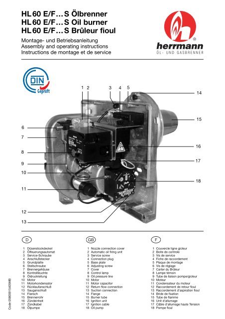
HL 60 E/F…S Ölbrenner<br />
HL 60 E/F…S Oil burner<br />
HL 60 E/F…S Brûleur fioul<br />
Montage- und Betriebsanleitung<br />
Assembly and operating instructions<br />
Instructions <strong>de</strong> montage et <strong>de</strong> service<br />
6<br />
7<br />
8<br />
9<br />
10<br />
11<br />
12<br />
13<br />
1 Düsenstock<strong>de</strong>ckel<br />
2 Ölfeuerungsautomat<br />
3 Service-Schraube<br />
4 Anschlußstecker<br />
5 Grundplatte<br />
6 Stellschraube<br />
7 Brennergehäuse<br />
8 Kontrollleuchte<br />
9 Öldruckleitung<br />
10 Motor<br />
11 Motorkon<strong>de</strong>nsator<br />
12 Rücklaufanschluß<br />
13 Sauganschluß<br />
14 Flansch<br />
15 Brennerrohr<br />
16 Zün<strong>de</strong>inheit<br />
17 Zündkabel<br />
18 Ölpumpe<br />
1 2 3 4<br />
1 Nozzle connection cover<br />
2 Automatic oil firing unit<br />
3 Service screw<br />
4 Connection plug<br />
5 Base plate<br />
6 Adjusting screw<br />
7 Cover<br />
8 Control lamp<br />
9 Oil pressure line<br />
10 Motor<br />
11 Motor capacitor<br />
12 Return flow connection<br />
13 Suction connection<br />
14 Flange<br />
15 Burner tube<br />
16 Ignition unit<br />
17 Ignition cable<br />
18 Oil pump<br />
5<br />
14<br />
15<br />
16<br />
17<br />
18<br />
1 Couvercle ligne gicleur<br />
2 Boite <strong>de</strong> controle<br />
3 Vis <strong>de</strong> service<br />
4 Fiche <strong>de</strong> raccor<strong>de</strong>ment<br />
5 Plaque <strong>de</strong> montage<br />
6 Vis <strong>de</strong> réglage<br />
7 Carter du Brûleur<br />
8 Lampe témoin<br />
9 Tube <strong>de</strong> liaison pompe/gicleur<br />
10 Moteur<br />
11 Con<strong>de</strong>nsateur du moteur<br />
12 Raccor<strong>de</strong>ment <strong>de</strong> retour fioul<br />
13 Raccor<strong>de</strong>ment d’aspiration fioul<br />
14 Bri<strong>de</strong> <strong>de</strong> fixation<br />
15 Tube <strong>de</strong> flamme<br />
16 Unit d’allumage<br />
17 Câble d’allumage haute Tension<br />
18 Pompe fioul
2<br />
Abbildung 1 / Figure 1<br />
Abbildung 2 / Figure 2<br />
Abbildung 3 / Figure 3<br />
Sehr geehrter Kun<strong>de</strong>,<br />
wir freuen uns, daß Sie sich für unser Brennerfabrikat entschie<strong>de</strong>n<br />
haben. Wir sind <strong>de</strong>r Überzeugung, daß lhre Entscheidung richtig war.<br />
Sie besitzen einen Markenölbrenner, <strong>de</strong>r unter Verwendung erstklassiger<br />
Brennerkomponenten gefertigt wur<strong>de</strong>. Je<strong>de</strong>r Brenner wird bei einer<br />
sorgfältigen Endkontrolle unter betriebsähnlichen Bedingungen geprüft.<br />
Sollte sich <strong>de</strong>nnoch ein Fehler eingeschlichen haben, was nach<br />
menschlichem Ermessen nie 100%ig ausgeschlossen wer<strong>de</strong>n kann, so<br />
lassen Sie uns dies bitte sofort wissen.<br />
Wir wer<strong>de</strong>n alles tun, um schnellstens im Rahmen unserer zweijährigen<br />
Werksgarantie das kostenlose Ersatzteil zu liefern. Sie haben auf alle<br />
Brennerbauteile (außer Düse) 2 Jahre Werksgarantie. Diese Montageund<br />
Betriebsanleitung enthält wichtige lnformationen für die Montage<br />
und Einstellung <strong>de</strong>s Ölbrenners. Wir empfehlen die Montage, lnbetriebnahme,<br />
Einregulierung und Wartung durch einen Fachmann ausführen zu<br />
lassen. Die je<strong>de</strong>m Brenner beigepackte Bedienungsanweisung muß<br />
gemäß DlN 4755 an sichtbarer Stelle im Heizraum aufgehängt und unbedingt<br />
vom Betreiber <strong>de</strong>r Ölfeuerungsanlage sorgfältig durchgelesen wer<strong>de</strong>n.<br />
Lassen Sie sich auch von lhrem lnstallateur bei <strong>de</strong>r Übergabe <strong>de</strong>r<br />
Anlage von <strong>de</strong>r Funktion und <strong>de</strong>r Bedienung <strong>de</strong>s Brenners unterrichten.<br />
Um über viele Jahre einen energiesparen<strong>de</strong>n und emissionsarmen<br />
Betrieb zu gewährleisten, sollten Sie wie auch in DlN 4755 empfohlen,<br />
lhre Ölfeuerungsanlage min<strong>de</strong>stens 1 mal im Jahr durch einen Fachmann<br />
warten lassen. Am besten im Rahmen eines Wartungsvertrages.<br />
Wir wünschen lhnen mit Ihrem neuen Ölbrenner einen energiesparen<strong>de</strong>n,<br />
umweltfreundlichen und störungsfreien Betrieb.<br />
Mit freundlicher Empfehlung<br />
Herrmann GmbH u. Co. KG<br />
Liststraße 8<br />
D-71336 Waiblingen<br />
Tel. +49 (0 )71 51/9 89 28-0<br />
Fax +49 (0 )71 51/9 89 28-49<br />
E-Mail info@<strong>herrmann</strong>-<strong>burners</strong>.<strong>de</strong><br />
Internet www.<strong>herrmann</strong>-<strong>burners</strong>.<strong>de</strong><br />
Inhaltsverzeichnis<br />
1. Technische Daten 4<br />
1.1 Brennerleistung 4<br />
1.2 Zulassung 4<br />
1.3 Arbeitsfeld 4<br />
1.4 Brennstoff 4<br />
1.5 Elektrische Daten 4<br />
1.6 Brennermaße 4<br />
1.7 Typenschlüssel 4<br />
1.8 Serienmäßiger Lieferumfang 4<br />
1.9 Brennerkomponenten und LE-System 6<br />
2. Montage 6<br />
2.1 Anschlußmaße 6<br />
2.2 Montage <strong>de</strong>s Brenners 6<br />
2.3 Serviceposition 6<br />
2.4 Wechsel <strong>de</strong>r Düse 6<br />
2.5 Düsentabelle 8<br />
2.6 Feuerraum-Min<strong>de</strong>stabmessungen 8<br />
2.7 Ölversorgung 8<br />
2.8 Ölleitungen - Dimensionen 8<br />
2.9 Ölanschluß am Brenner 10<br />
2.10 Elektroanschluß 10<br />
2.11 Allgemeine Kontrollen 10<br />
3. Inbetriebnahme 10<br />
3.1 Einregulierung <strong>de</strong>s Brenners 12<br />
3.2 Kaminzug 12<br />
3.3 Verbrennungsluft 12<br />
3.4 Rußzahl 12<br />
3.5 Öldruck 14<br />
3.6 Abgasverluste 14<br />
3.7 Abschluß und Sicherheitsprüfung 14<br />
3.8 Schornstein 16<br />
3.9 Abgasthermometer 16<br />
3.10 Betriebsstun<strong>de</strong>nzähler 16<br />
3.11 Heizölzähler 16
Dear Customer,<br />
we are pleased about your <strong>de</strong>cision to purchase this oil burner.<br />
We are convinced that your <strong>de</strong>cision was the right one. You now have a<br />
brandname oil burner, which was produced using first-class burner<br />
components. Each single burner has been subjected to a thorough final<br />
inspection and tested un<strong>de</strong>r operation-simulated conditions.<br />
However, if a fault does happen to arise, which can never be 100 percent<br />
exclu<strong>de</strong>d as far as is humanly possible, please inform us of this immediately.<br />
We will do everything in our power to supply you with spare parts<br />
as quickly as possible free of charge in the scope of our two-years factory<br />
guarantee. You have a factory guarantee of two years on all burner<br />
components (except for the nozzle). These assembly and operating<br />
instructions contain important information for the assembly and adjustment<br />
of the oil burner. We recomend having the assembly, initial operation,<br />
adjustment and maintenance carried out by a specialist. The operating<br />
instructions inclu<strong>de</strong>d with each burner must be posted up at<br />
clearly visible places in the heating room in accordance with DlN 4755<br />
and must be carefully read by the operator of the oil firing system. Have<br />
your installation mechanic inform you about the burner functions and<br />
operation with transfer of the system. ln or<strong>de</strong>r to guarantee efficient and<br />
non-polluting operation for many years to come, you should have your<br />
oil firing system serviced at least once per year by a specialist, as<br />
recommen<strong>de</strong>d in DlN 4755. This can be performed the best in the scope<br />
of a service contract. We wish you enjoy energy-saving, non polluting<br />
and fault-free operation of your new oil burner system.<br />
Yours faithfully,<br />
Herrmann GmbH u. Co. KG<br />
Liststraße 8<br />
D-71336 Waiblingen / Germany<br />
Phone +49 (0 )71 51/9 89 28-0<br />
Fax +49 (0 )71 51/9 89 28-49<br />
E-Mail info@<strong>herrmann</strong>-<strong>burners</strong>.<strong>de</strong><br />
Internet www.<strong>herrmann</strong>-<strong>burners</strong>.<strong>de</strong><br />
Table of contents<br />
1. Technical data 5<br />
1.1 Burner performance 5<br />
1.2 Approval 5<br />
1.3 Operating range 5<br />
1.4 Fuel 5<br />
1.5 Electrical data 5<br />
1.6 Burner dimensions 5<br />
1.7 Type co<strong>de</strong> 5<br />
1.8 Standard scope of <strong>de</strong>livery 5<br />
1.9 Burner components and LE system 7<br />
2. Assembly 7<br />
2.1 Connection dimensions 7<br />
2.2 Assembly of the burner 7<br />
2.3 Service position 7<br />
2.4 Change of the nozzle 7<br />
2.5 Nozzle table 9<br />
2.6 Furnace - minimum dimensions 9<br />
2.7 Oil supply 9<br />
2.8 Oil line dimensions 9<br />
2.9 Oil connection to the burner 11<br />
2.10 Electrical connection 11<br />
2.11 General inspections 11<br />
3. Initial operation 11<br />
3.1 Adjusting the burner 13<br />
3.2 Chimney draft 13<br />
3.3 Combustion air 13<br />
3.4 Soot number 13<br />
3.5 Oil pressure 15<br />
3.6 Exhaust gas loss 15<br />
3.7 Final and safety tests 15<br />
3.8 Chimney 17<br />
3.9 Exhaust gas thermometer 17<br />
3.10 Hours of operation counter 17<br />
3.11 Heating oil meter 17<br />
Cher Client,<br />
nous sommes heureux que vous ayez choisi un brûleur <strong>de</strong> notre fabrication.<br />
Nous sommes convaincus que vous avez fait le bon choix. Vous possé<strong>de</strong>z<br />
à présent un brûleur fioul <strong>de</strong> qualité, fabriqué à partir <strong>de</strong> composants<br />
<strong>de</strong> première qualité. Chaque brûleur est soumis à un contrôle final<br />
rigoureux, dans <strong>de</strong>s conditions analogues à celles <strong>de</strong> son utilisation<br />
future. Cependant, si un défaut avait quand même échappé à notre vigilance,<br />
ce qui, humainement, ne peut jamais être exclu à 100%, veuillez<br />
nous le communiquer aussitôt. Nous ferons le nécessaire pour vous<br />
remplacer le plus vite possible et gratuitement la pièce défectueuse,<br />
dans le cadre <strong>de</strong> notre garantie d’<strong>de</strong>ux ans. Toutes les pièces du brûleur<br />
(exceptée la buse) sont garanties d’<strong>de</strong>ux ans. Ces instructions <strong>de</strong> montage<br />
et <strong>de</strong> service contiennent <strong>de</strong>s informations importantes concernant<br />
le montage et le réglage du brûleur fioul. Nous vous conseillons <strong>de</strong> confier<br />
le montage, la mise en service, le réglage et l’entretien à un spécialiste.<br />
Conformément aux dispositions DlN 4755, les instructions <strong>de</strong> service<br />
qui accompagnent chaque appareil doivent être affichées bien en<br />
vue dans la salle <strong>de</strong> chauffage et impérativement lues avec attention par<br />
l’utilisateur <strong>de</strong> l’installation fioul. Lors <strong>de</strong> la réception <strong>de</strong> l’appareil, faites-vous<br />
expliquer par votre installateur le fonctionnement et le maniement<br />
du brûleur. Afin <strong>de</strong> garantir un fonctionnement pauvre en émissions<br />
et économisant l’énergie sur <strong>de</strong> nombreuses années, vous <strong>de</strong>vriez,<br />
comme le recomman<strong>de</strong>nt également les dispositions DlN 4755, faire<br />
réviser votre brûleur à fioul au moins une fois par an par un spécialiste,<br />
<strong>de</strong> préférence dans le cadre d’un contrat <strong>de</strong> maintenance. Nous vous<br />
souhaitons une agréable utilisation <strong>de</strong> votre nouveau brûleur fioul.<br />
Avec nos meilleures recommandations<br />
Herrmann GmbH u. Co. KG<br />
Liststraße 8<br />
D-71336 Waiblingen / Allemagne<br />
Téléphone +49 (0 )71 51/9 89 28-0<br />
Télécopie +49 (0 )71 51/9 89 28-49<br />
E-Mail info@<strong>herrmann</strong>-<strong>burners</strong>.<strong>de</strong><br />
Internet www.<strong>herrmann</strong>-<strong>burners</strong>.<strong>de</strong><br />
Sommaire<br />
1. Caractéristiques techniques 5<br />
1.1 Puissance du brûleur 5<br />
1.2 Homologation 5<br />
1.3 Champ d’activité 5<br />
1.4 Combustible 5<br />
1.5 Equipement électrique 5<br />
1.6 Dimensions du brûleur 5<br />
1.7 Co<strong>de</strong> <strong>de</strong> désignation du modèle 5<br />
1.8 Equipement <strong>de</strong> série 5<br />
1.9 Composants du brûleur et système LE 7<br />
2. Montage 7<br />
2.1 Cotes <strong>de</strong> raccor<strong>de</strong>ment 7<br />
2.2 Montage du brûleur 7<br />
2.3 Position <strong>de</strong> service 7<br />
2.4 Changement du gicleur 7<br />
2.5 Tableau <strong>de</strong>s gicleurs 9<br />
2.6 Dimensions minimales du foyer 9<br />
2.7 Alimentation fioul 9<br />
2.8 Dimensions <strong>de</strong>s canalisations <strong>de</strong> fioul 9<br />
2.9 Raccor<strong>de</strong>ment dufioul au brûleur 11<br />
2.10 Raccor<strong>de</strong>ment électrique 11<br />
2.11 Contrôles généraux 11<br />
3. Mise en service 11<br />
3.1 Réglage du brûleur 13<br />
3.2 Tirage 13<br />
3.3 Air <strong>de</strong> combustion 13<br />
3.4 Indice <strong>de</strong> noircissement 13<br />
3.5 Pression du fioul 15<br />
3.6 Pertes <strong>de</strong> fumées 15<br />
3.7 Fermeture et contrôle <strong>de</strong> sécurité 15<br />
3.8 Tirage <strong>de</strong> cheminée 17<br />
3.9 Thermomètre <strong>de</strong> gaz d’échappement 17<br />
3.10 Compteur d’heures <strong>de</strong> service 17<br />
3.11 Compteur <strong>de</strong> fioul 17<br />
3
4<br />
Abbildung 4 / Figure 4<br />
Abbildung 5 / Figure 5<br />
Abbildung 6 / Figure 6<br />
1. Technische Daten<br />
1.1 Brennerleistung<br />
Type Öldurchsatz Brenner- Heizgeräteleistung<br />
leistung*<br />
<strong>HL60</strong> ELV.2-S 1,3 - 3,5 kg/h 16 - 42 kW 14 - 37 kW<br />
<strong>HL60</strong> FLV.2-S 3,0 - 5,5 kg/h 36 - 65 kW 33 - 60 kW<br />
* Angaben für Geräte mit einem Feuerraumdruck von ± 0 mbar und<br />
einem Abgasverlust von ca. 8 %.<br />
1.2 Zulassung<br />
DIN EN 267, Emissionsgrenzwerte Klasse 3<br />
Register-Nummer für <strong>HL60</strong>…5G966/2001<br />
1.3 Arbeitsfeld<br />
Aus <strong>de</strong>r Grafik ist <strong>de</strong>r Öldurchsatz <strong>de</strong>s Brenners in Abhängigkeit<br />
vom Feuerraumdruck ersichtlich (siehe Abb. 4). Die Arbeitsfel<strong>de</strong>r<br />
sind auf <strong>de</strong>m Prüfstand ermittelt wor<strong>de</strong>n und beziehen sich auf<br />
eine Höhe von ca. 100 m über NN und eine Raumtemperatur von<br />
ca. 20°C. Der in <strong>de</strong>r Praxis erreichbare Öldurchsatz ist abhängig<br />
vom Anfahrwi<strong>de</strong>rstand <strong>de</strong>s Wärmeerzeugers.<br />
Der Anfahrwi<strong>de</strong>rstand wird durch <strong>de</strong>n Feuerraum, die Rauchgasführung<br />
und durch die Anfahrlast beeinflußt. Genaue Werte können<br />
daher nur an <strong>de</strong>r jeweiligen Anlage ermittelt wer<strong>de</strong>n.<br />
1.4 Brennstoff<br />
Heizöl EL nach DlN 51603-1<br />
Viskosität max. 6,0 mm 2 /s bei 20°C<br />
1.5 Elektrische Daten<br />
Nennspannung 230 V~ (+10 % - 15 %) 50 Hz<br />
Anfahrleistung ca. 435 Watt<br />
Betriebsleistung ca. 135 - 235 Watt<br />
Kontaktbelastung <strong>de</strong>r Thermostate und Schalter min. 6A~<br />
1.6 Brennermaße<br />
Maßangabe in mm (siehe Abb. 5)<br />
Verpackung (LxBxH) 365 x 350 x 485 mm<br />
Transportgewicht 13,2 kg<br />
1.7 Typenschlüssel<br />
HL 60 ELV.2-S<br />
1.8 Serienmäßiger Lieferumfang<br />
Herrmann Brenner<br />
Heizölsorte EL<br />
Baugröße<br />
Mischeinrichtung<br />
Luftklappe<br />
Ölvorwärmer<br />
Gebläserad-Größe<br />
Son<strong>de</strong>rprüfung nach RAL UZ9<br />
1 Ölbrenner<br />
1 Ab<strong>de</strong>ckhaube<br />
1 Dichtung für Flansch<br />
1 Flansch<br />
2 Ölschläuche 110 cm lang, montiert<br />
1 Tülle für Ölschlauch<br />
1 Tülle blind<br />
4 Befestigungsschrauben M8 x 30<br />
4 Scheiben<br />
1 Innensechskantschlüssel 4 mm<br />
1 Montage- und Betriebsanleitung<br />
1 Ölbrenner-Bedienungsanweisung<br />
1 Befestigungsstahlstift für Ölbrenner-Bedienungsanweisung
1. Technical Data<br />
1.1 Burner performance<br />
Type Oil flow Burner Heater<br />
performance performance*<br />
HL 60 ELV.2-S 1,3 - 3,5 kg/h 16 - 42 kW 14 - 37 kW<br />
HL 60 FLV.2-S 3,0 - 5,5 kg/h 36 - 65 kW 33 - 60 kW<br />
* Specifications for units with a furnace pressure of ±0 mbar and an<br />
exhaust gas loss of approx. 8 %.<br />
1.2 Approval<br />
DlN EN 267, emission limits class 3<br />
Register number for HL 60…5G966/2001<br />
1.3 Operating range<br />
ln the chart, it can be seen that the oil flow of the burner is a function<br />
of the furnace pressure (see fig. 4). The operating ranges have<br />
been <strong>de</strong>termined on a testing unit and refer to an altitu<strong>de</strong> of approx.<br />
100 m above sea-level and a room temperature of approx. 20°C.<br />
The oil flow that can be achieved in practice <strong>de</strong>pends on the starting<br />
resistance of the heater.<br />
The starting resistance is influenced by the furnace, the flue gas line<br />
and the starting load. Exact values can therefore only be <strong>de</strong>termined<br />
on each respective system.<br />
1.4 Fuel<br />
Heating oil EL according to DlN 51603-1<br />
Viscosity max. 6,0 mm 2 /s at 20°C<br />
1.5 Electrical data<br />
Rated voltage 230 V~ (+10 % - 15 %) 50 Hz<br />
Starting performance approx. 435 Watts<br />
Operating performance approx.135 - 235 Watts<br />
Contact load of the thermostats and switches, min. 6A~<br />
1.6 Burner dimensions<br />
Specifications of dimensions in mm (see fig. 5)<br />
Packing (lxbxh) 365 x 350 x 485 mm<br />
Transport weight 13,2 kg<br />
1.7 Type co<strong>de</strong><br />
HL 60 ELV.2-S<br />
1.8 Standard scope of <strong>de</strong>livery<br />
Herrmann-Burner<br />
Type of heating oil EL<br />
Size<br />
Mixing unit<br />
Air flap<br />
Oil preheater<br />
Blower wheel size<br />
Spezial test according to RAL UZ 9<br />
1 Oil burner<br />
1 Cover<br />
1 Gasket for flange<br />
1 Flange<br />
2 Oil hoses, 110 cm long, mounted<br />
1 Sleeve for oil hose<br />
1 Sleeve, blank<br />
4 Mounting screws M8 x 30<br />
4 Plates<br />
1 Hexagon socket wrench 4 mm<br />
1 Assembly and operating instructions<br />
1 Oil burner operating instructions<br />
1 Mounting pin for oil burner operating instructions<br />
1. Caractéristiques techniques<br />
1.1 Puissance du brûleur<br />
Type Débit <strong>de</strong> fioul Puissance Puissance <strong>de</strong>s<br />
du brûleur chaudières*<br />
HL 60 ELV.2-S 1,3 - 3,5 kg/h 16 - 42 kW 14 - 37 kW<br />
HL 60 FLV.2-S 3,5 - 5,5 kg/h 36 - 65 kW 33 - 60 kW<br />
* lndications concernant les appareils ayant une pression <strong>de</strong><br />
chauffe <strong>de</strong> ±0 mbar et une perte <strong>de</strong> fumée d’environ 8 %.<br />
1.2 Homologation<br />
DlN EN 267, limites d' émission 3<br />
Numéro <strong>de</strong> registre HL 60…5G966/2001<br />
1.3 Champ d’activité<br />
Le graphique montre le débit <strong>de</strong> fioul du brûleur en fonction <strong>de</strong> la<br />
pression <strong>de</strong> chauffe (Cf. fig. 4). Les champs d’activité ont été établis<br />
sur le banc d’essai et se rapportent à une hauteur d’environ 100<br />
m au-<strong>de</strong>ssus <strong>de</strong> NN et à une température ambiante d’environ 20°C.<br />
Le débit <strong>de</strong> fioul que l’on obtient dans la pratique dépend <strong>de</strong> la résistance<br />
au démarrage <strong>de</strong> la source calorifique.<br />
La résistance au démarrage étant variable en fonction <strong>de</strong> la chambre<br />
<strong>de</strong> combustion, <strong>de</strong> la conduite <strong>de</strong>s gaz <strong>de</strong> combustion et <strong>de</strong> la<br />
charge <strong>de</strong> démarrage, <strong>de</strong>s valeurs exactes ne peuvent être communiquées<br />
que cas par cas.<br />
1.4 Combustible<br />
Fioul conforme à DlN 51603-1<br />
Viscosité max. 6,0 mm 2 /s à une témperature<br />
<strong>de</strong> 20°C<br />
1.5 Equipement électrique<br />
Tension nominale 230 V~ (+10 % - 15 %) 50 Hz<br />
Puissance <strong>de</strong> démarrage env. 435 Watts<br />
Puissance <strong>de</strong> service env. 135 - 235 Watts<br />
Charge <strong>de</strong> contact <strong>de</strong>s thermostats et <strong>de</strong>s commutateurs min. 6 A~<br />
1.6 Dimensions du brûleur<br />
Dimensions en mm (Cf. fig. 5)<br />
Emballage (lxdxh) 365 x 350 x 485 mm<br />
Poids <strong>de</strong> transport 13,2 kg<br />
1.7 Co<strong>de</strong> <strong>de</strong> désignation du modèle<br />
HL 60 ELV.2-S<br />
1.8 Equipement <strong>de</strong> série<br />
Herrmann-Brûleur<br />
Type <strong>de</strong> fioul<br />
Taille <strong>de</strong> construction<br />
Dispositif <strong>de</strong> mélange<br />
Clapet d’aération<br />
Réchauffeur <strong>de</strong> fioul<br />
Taille <strong>de</strong> la roue du ventilateur<br />
Essai spécial d’après les normes<br />
RAL UZ 9<br />
1 Brûleur fioul<br />
1 Capot brûleur<br />
1 Joint <strong>de</strong> bri<strong>de</strong><br />
1 Bri<strong>de</strong><br />
2 Flexibles fioul <strong>de</strong> 110 cm <strong>de</strong> longueur<br />
1 Passe-câble pour conduite <strong>de</strong> mazout<br />
1 Douille aveugle<br />
4 Vis <strong>de</strong> fixation M8 x 30<br />
4 Ron<strong>de</strong>lles<br />
1 Clé à six pans creux <strong>de</strong> 4 mm<br />
1 Instruction <strong>de</strong> montage et <strong>de</strong> service<br />
1 Instruction <strong>de</strong> service du brûleur<br />
1 Pointe <strong>de</strong> fixation pour l’instruction <strong>de</strong> service du brûleur<br />
5
6<br />
Abbildung 7 / Figure 7<br />
Abbildung 8 / Figure 8<br />
Abbildung 9 / Figure 9<br />
1<br />
2<br />
3<br />
1.9 Brennerkomponenten<br />
Motor FHP/AEG EB 95 C 28/2<br />
Kon<strong>de</strong>nsator Arcotronics 3µF 400 V DB<br />
Ölpumpe Danfoss BFP 21 L3<br />
Magnetspule Danfoss 071G0051<br />
Ölvorwärmer Danfoss FPHB 5<br />
Zün<strong>de</strong>inheit Danfoss EBI 052F0030<br />
Fotowi<strong>de</strong>rstand Danfoss LDS057H<br />
Ölfeuerungsautomat Siemens LMO 14<br />
Ölfeuerungsautomat WLE Siemens LMO 44<br />
Technische Daten Ölfeuerungsautomat<br />
Siemens LMO 14 LMO 44 (WLE)<br />
Nennspannung 197 - 253 V~ 197 - 253 V~<br />
Frequenz 50 - 60 Hz ±6 %50 - 60 Hz ±6 %<br />
Leistungsaufnahme 12 VA 12 VA<br />
Vorzündzeit 15 s 25 s<br />
Nachzündzeit 10 s 5 s<br />
Vorbelüftungszeit 16 s 26 s<br />
Sicherheitszeit max. 10 s max. 5 s<br />
Fotostrom-Betrieb 45 - 100 µA 45 - 100 µA<br />
Fotostrom-Anlauf max. 5,5 µA max. 5,5 µA<br />
Netzsicherung max. 5 A max. 5 A<br />
Achtung: Das Öffnen <strong>de</strong>s Ölfeuerungsautomaten ist nicht er-<br />
laubt, es kann zu unabsehbaren Folgen führen.<br />
Bei Warmlufterzeugern nach DIN 4791 muß <strong>de</strong>r Ölfeuerungsautomat<br />
LMO 44 verwen<strong>de</strong>t wer<strong>de</strong>n.<br />
Der Brenner ist serienmäßig mit einem LE-System (LE-Ölpumpe,<br />
LE-Ölvorwärmer) ausgestattet. Das LE-System verringert die<br />
Schadstoffe und ist werkseitig auf LE-Betrieb eingestellt.<br />
Zusätzlich ist ein Vorfilter (Filtrierungsgrad max. 40 µm) notwendig.<br />
2. Montage<br />
2.1 Anschlußmaße<br />
Anschlußmaße zwischen Brenner und Wärmeerzeuger nach<br />
DIN EN 226 (Maße in mm) siehe Abb. 7.<br />
2.2 Montage <strong>de</strong>s Brenners<br />
Den Flansch inklusive <strong>de</strong>r Dichtung am Wärmeerzeuger montieren.<br />
Den Brenner mit <strong>de</strong>m Brennerrohr in <strong>de</strong>n Flansch einführen, bis das<br />
Brennerrohr mit <strong>de</strong>r Feuerrauminnen<br />
seite bündig ist. Etwaige Son<strong>de</strong>rvorschriften <strong>de</strong>s Wärmeerzeuger-<br />
Herstellers beachten. Die Klemmschraube <strong>de</strong>s Befestigungsflansches<br />
fest anziehen.<br />
Achtung: Der Flansch ist lageabhängig.<br />
Beim Einsatz <strong>de</strong>s Brenners als Sturzbrenner ist zusätzlich eine<br />
konische Dichtung erfor<strong>de</strong>rlich und die Luftklappe muß ausgebaut<br />
wer<strong>de</strong>n.<br />
2.3 Serviceposition<br />
Die Service-Schraube mit Innensechskant-Schlüssel 4 mm mit<br />
einer 1/2 Umdrehung lösen (siehe Abb. 8), <strong>de</strong>n Brenner nach links<br />
verdrehen und aus <strong>de</strong>m Brennerrohr herausziehen. Anschließend in<br />
<strong>de</strong>r Serviceposition einhängen (siehe Abb. 9).<br />
2.4 Wechsel <strong>de</strong>r Düse<br />
- Schraube 2 mit Innensechskant-Schlüssel 4 mm lösen und<br />
Stauscheibe 1 abnehmen (siehe Abb. 9).<br />
- Düse 3 nach erfor<strong>de</strong>rlichem Leistungsbereich auswählen<br />
(siehe Abb. 19).<br />
- Vorhan<strong>de</strong>ne Düse 3 entfernen und gewählte Düse einschrauben<br />
(siehe Abb. 9).<br />
- Abstand zwischen Stauscheibe und Düse (siehe Abb. 10).<br />
- Stauscheibe 1 bis Anschlag aufsetzen und die Schraube 2<br />
anziehen.<br />
Achtung: Stauscheibe und Düse können heiß sein!<br />
Verletzungsgefahr!
1.9 Burner components<br />
Motor FHP/AEG EB 95 C 28/2<br />
Capacitor Arcotronics 3µF 400 V DB<br />
Oil pump Danfoss BFP 21<br />
Solenoid coil Danfoss 071G0051<br />
Oil preheater Danfoss FPHB 5<br />
Ignition unit Danfoss EBI 052F0030<br />
Photo-resistor Danfoss LDS057H<br />
Automatic oil firing unit Siemens LMO 14<br />
Automatic oil firing unit WLE Siemens LMO 44<br />
Technical data of the automatic oil firing unit<br />
Siemens LMO 14 LMO 44 (WLE)<br />
Rated voltage 197 - 253 V~ 197 - 253 V~<br />
Frequency 50 - 60 Hz ±6 % 50 - 60 Hz ±6 %<br />
Power consumption 12 VA 12 VA<br />
Pre-ignition 15 s 25 s<br />
Re-ignition 10 s 5 s<br />
Prepurge 16 s 26 s<br />
Safety time max. 10 s max. 5 s<br />
Photo-current operation 45 - 100 µA 45 - 100 µA<br />
Photo-current start-up max. 5,5 µA max. 5,5 µA<br />
Main fuse max. 5 A max. 5 A<br />
Attention: Opening the automatic oil firing unit is not permitted,<br />
opening could have unforeseeable consequences.<br />
With air heaters according to DIN 4791, the automa<br />
tic oil firing unit LMO 44 must be used.<br />
The burner is in series equipped with a LE system (LE - Oilpump,<br />
LE - Oil preheater). The LE system reduces the pollutants<br />
and is by the factory adjusted to LE operation.<br />
Additionally a prescreener (filtration <strong>de</strong>gree of max. 40 µm) is<br />
necessary.<br />
2. Assembly<br />
2.1 Assembly dimensions<br />
Connection dimensions between the burner and heater according<br />
to DIN EN 226 (dimensions in mm), see fig. 7.<br />
2.2 Assembly of the <strong>burners</strong><br />
Mounting the flange including the seal into the heater. Insert the<br />
burner with the burner pipe into the flange until the burner pipe is<br />
flush with the inner si<strong>de</strong> of the combustion chamber. Observe all of<br />
the special instructions of the manufacturer of the heater. Tighten<br />
the clamping screw of the mounting flange.<br />
Achtung: The flange must be in the right position.<br />
With the use of the burner as a pack burner, a conical seal is additionally<br />
necessary and the air flap must be disassebmled.<br />
2.3 Service position<br />
Loosen the service screw by 1/2 turn using a 4 mm hexagon socket<br />
wrench (see fig. 8). Turn the burner to the left and remove it from<br />
the burner pipe. After that, replace it in the <strong>de</strong>sired service position<br />
(see fig. 9).<br />
2.4 Change of the nozzle<br />
- Loosen screw 2 using a 4 mm hexagon socket wrench and<br />
remove the baffle plate 1 (see fig. 9).<br />
- Select the nozzle 3 according to the required performance<br />
range (see fig. 19).<br />
- Remove present nozzle 3 and screw on the selected nozzle<br />
(see fig. 9).<br />
- For the distance between baffle plate and nozzle (see fig. 10).<br />
- Install the baffle plate 1 until stop and tighten the screw 2.<br />
Attention: The baffle plate and nozzle could be hot!<br />
Injury danger!<br />
1.9 Composants du brûleur<br />
Moteur FHP/AEG EB 95 C 28/2<br />
Con<strong>de</strong>nsateur Arcotronics 3µF 400 V DB<br />
Pompe Danfoss BFP 21<br />
Bobine magnétique Danfoss 071G0051<br />
Réchauffeur <strong>de</strong> fioul Danfoss FPHB 5<br />
Unit d’allumage Danfoss EBI 052F0030<br />
Cellule photo-résistante Danfoss LDS057H<br />
Boite <strong>de</strong> Controle Siemens LMO 14<br />
Boite <strong>de</strong> Controle Siemens LMO 44 (WLE<br />
Caractéristiques techniques du dispositif d’allumage automatique<br />
Siemens LMO 14 LMO 44 (WLE)<br />
Tension nominale 197 - 253 V~ 197 - 253 V~<br />
Fréquence 50 - 60 Hz ±6% 50 - 60 Hz ±6 %<br />
Puissance absorbée 12 VA 12 VA<br />
Temps <strong>de</strong> d’avance à l’allumage 15 s 25 s<br />
Temps <strong>de</strong> retard à l’allumage 10 s 5 s<br />
Temps <strong>de</strong> préventilation 16 s 26 s<br />
Temps <strong>de</strong> sécurité 10 sec max. 5 sec max.<br />
Valeur du courant <strong>de</strong> la cellule<br />
En service 45 - 100 µA 45 - 100 µA<br />
Mise en marche du courant<br />
Eu mo<strong>de</strong> d’allumage max. 5,5 µA max. 5,5 µA<br />
Fusible <strong>de</strong> secteur 5 A max. 5 A max.<br />
Attention: Il est interdit d’ouvrir le boitier <strong>de</strong> controle, cela risquerait<br />
d’avoir <strong>de</strong>s conséquences imprévisibles.<br />
2. Montage<br />
Pour les sources d’air chaud conformes aux normes<br />
DIN 4791, il faut utiliser le dispositif d’allumage automatique<br />
<strong>de</strong> type LMO 44.<br />
2.1 Dimensions <strong>de</strong> raccor<strong>de</strong>ment<br />
Les dimensions <strong>de</strong> raccor<strong>de</strong>ment entre le brûleur et la source calorifique<br />
sont conformes aux normes DIN EN 226 (dimensions<br />
en mm), Cf. fig. 7.<br />
2.2 Montage du brûleur<br />
Monter la bri<strong>de</strong> et son joint sur la chaufferie. Introduire le brûleur et<br />
son tube <strong>de</strong> combustion dans la bri<strong>de</strong> jusqu’à ce que celui-ci soit à<br />
niveau avec la paroi intérieure <strong>de</strong> la chambre <strong>de</strong> combustion.<br />
Respecter les directives spéciales éventuelles du fabricant <strong>de</strong> la<br />
chaufferie. Serrer à fond la vis <strong>de</strong> blocage <strong>de</strong> la bri<strong>de</strong> <strong>de</strong> fixation.<br />
Attention: La collerette ne peut pas être placée dans n’importe<br />
quelle position.<br />
Lorsqu’on emloie le brûleur comme brûleur <strong>de</strong> déchargement, il faut<br />
utiliser un joint d’étanchéité conique d´monter le clapet<br />
d’aération.<br />
2.3 Position <strong>de</strong> service<br />
A l’ai<strong>de</strong> d’une clé à six pans creux <strong>de</strong> 4 mm, <strong>de</strong>sserrer la vis <strong>de</strong> service<br />
d’1/2 tour (Cf. fig 8), tourner le brûleur vers; la gauche et le retirer<br />
du tuyau. Le mettre en suite dans la position <strong>de</strong> service désirée<br />
(Cf. fig. 9).<br />
2.4 Changement du gicleur<br />
- A l’ai<strong>de</strong> d’une clé à six pans creux <strong>de</strong> 4 mm, dévisser la vis 2 et<br />
retirer l’écran réducteur <strong>de</strong> pression (Cf. fig. 9).<br />
- Choisir le gicleur 3 qui convient à la puissance nécessaire<br />
(Cf. fig. 19).<br />
- Retirer le gicleur 3 en place et visser le nouveau gicleur (Cf. fig. 9).<br />
- Ecart entre l’écran réducteur <strong>de</strong> pression et le gicleur (Cf. fig. 10).<br />
- Placer l’écran réducteur 1 l'affiche <strong>de</strong> pression et visser la vis 2.<br />
Attention: Il est possible que l’écran réducteur <strong>de</strong> pression et<br />
le gicleur soient brûlants! Danger d’blessure!<br />
7
8<br />
Abbildung 10 / Figure 10<br />
Abbildung 11 / Figure 11<br />
Abbildung 12 / Figure 12<br />
- Die Einstellmaße <strong>de</strong>r Zün<strong>de</strong>lektro<strong>de</strong>n sind zu prüfen bzw.<br />
einzustellen (siehe Abb. 10).<br />
Anschließend <strong>de</strong>n Brenner in Betriebsposition bringen und<br />
Service-Schraube anziehen.<br />
2.5 Düsentabelle<br />
Die in <strong>de</strong>r Düsentabelle angegebenen Öldurchsätze (siehe Abb. 19)<br />
beziehen sich auf eine Viskosität <strong>de</strong>s vorgewärmten Heizöls von ca.<br />
2,0 mm 2 /s.<br />
2.6 Feuerraum-Min<strong>de</strong>stabmessungen<br />
Emissionsarme Verbrennungswerte sind nur unter Einhaltung <strong>de</strong>r<br />
Feuerraum-Min<strong>de</strong>stabmessungen möglich (siehe Abb. 20).<br />
2.7 Ölversorgung<br />
Die Errichtung und Ausführung <strong>de</strong>r Anlage hat nach DlN 4755 zu<br />
erfolgen. Örtliche Vorschriften sind zu beachten. Die Ölleitung ist<br />
soweit an <strong>de</strong>n Brenner heranzuführen, daß die Ölschläuche zugentlastet<br />
angeschlossen wer<strong>de</strong>n können. ln die Verbindung ist<br />
saugseitig ein Ölfilter mit Schnellschlußhahn einzubauen. In die<br />
Rücklaufleitung ist ein Rückschlagventil zu installieren. Der Brenner<br />
kann im 1- und 2-Rohr-System betrieben wer<strong>de</strong>n. Serienmäßig<br />
wird <strong>de</strong>r Brenner für 2-Rohr-Systeme geliefert. Das Vakuum in <strong>de</strong>r<br />
Saugleitung darf 0,4 bar nicht überschreiten. Bei einer Saughöhe<br />
über 3,5 m muß eine Ölför<strong>de</strong>rpumpe eingebaut wer<strong>de</strong>n. Beim<br />
Betrieb mit Ölför<strong>de</strong>rpumpe o<strong>de</strong>r wenn <strong>de</strong>r Öltank höher liegt als die<br />
Brennerpumpe, muß <strong>de</strong>r Brenner im 1-Rohr-System betrieben wer<strong>de</strong>n.<br />
Wird <strong>de</strong>r Brenner im 1-Rohr-System betrieben, muß an<br />
<strong>de</strong>r Brennerpumpe <strong>de</strong>r Rücklauf R verschlossen wer<strong>de</strong>n und die<br />
Schraube G ist unbedingt zu entfernen (siehe Abb. 11).<br />
Der Druck in <strong>de</strong>r Ölleitung darf 1,5 bar nicht überschreiten. Nach<br />
Fertigstellung <strong>de</strong>r Ölleitungen muß eine Dichtheitskontrolle mit<br />
einem Druck von min. 5 bar entsprechend DlN 4755 durchgeführt<br />
wer<strong>de</strong>n. Der Brenner darf während <strong>de</strong>r Dichtheitskontrolle nicht<br />
angeschlossen sein.<br />
2.8 Ölleitungen-Dimensionen<br />
Ölpumpe Danfoss BFP 21 L3, Heizöl EL 6,0 mm 2 /s bei +20°C<br />
Werte für 8,4 mm 2 /s bei +8°C<br />
Saugleitungslänge, 2-Rohr-System, Tank tiefer (siehe Abb. 12).<br />
Höhe H Ø 6 mm Ø 8 mm Ø 10 mm<br />
0,0 m 17 m 53 m 100 m<br />
0,5 m 15 m 47 m 100 m<br />
1,0 m 13 m 41 m 99 m<br />
1,5 m 11 m 34 m 84 m<br />
2,0 m 19 m 28 m 68 m<br />
2,5 m 17 m 22 m 53 m<br />
3,0 m 15 m 15 m 37 m<br />
3,5 m 13 m 9 m 22 m<br />
Saugleitungslänge, 1-Rohr-System, Tank höher (siehe Abb. 12).<br />
Höhe H Ø 6 mm Ø 6 mm Ø 8 mm<br />
4,0 m 100 m 100 m 100 m<br />
3,5 m 100 m 100 m 100 m<br />
3,0 m 100 m 197 m 100 m<br />
2,5 m 100 m 181 m 100 m<br />
2,0 m 100 m 165 m 100 m<br />
1,5 m 197 m 149 m 177 m<br />
1,0 m 165 m 132 m 151 m<br />
0,5 m 132 m 116 m 126 m<br />
Düse bis 2,5 kg/h bis 5,0 kg/h bis 10,0 kg/h<br />
Ø = Innendurchmesser
- The settings of the ignition electro<strong>de</strong>s are to be inspected<br />
and/or re-adjusted (see fig. 10).<br />
After that, bring the burner to the operating position and tighten<br />
the service screw.<br />
2.5 Nozzle table<br />
The oil flow specified in the nozzle table (see fig. 19) refer to a viscosity<br />
of the preheated heating oil of approx. 2 mm 2 /s.<br />
2.6 Furnace – minimum dimensions<br />
Combustion values low on emissions according are only possible with<br />
compliance with the furnace minimum dimensions (see fig. 20).<br />
2.7 Oil supply<br />
The construction and installation of the system is to be carried out<br />
according to DlN 4755. Local regulations are to be observed. The<br />
oil line is to be installed to the burner such that the oil hoses can<br />
be connected without any tension. An oil filter with a quick-close<br />
valve is to be installed in the connection on the suction si<strong>de</strong>.<br />
A return check valve is to be installed in the return flow line.<br />
The burner can be operated in a 1 and 2 pipe system. The burner<br />
is <strong>de</strong>livered for a 2-pipe system as standard. The vacuum in the<br />
suction line may not exceed 0.4 bar. With a suction height of more<br />
than 3.5 m, an oil circulation pump must be installed. With operation<br />
with an oil circulation pump or if the oil tank is located higher<br />
than the burner pump, the burner must be operated as a 1-pipe<br />
system. lf the burner is operated as a 1-pipe system, the return flow<br />
R must be closed at the burner pump and screw G must be removed<br />
(see fig. 11).<br />
The pressure in the oil line may not exceed 1.5 bar. After complete<br />
installation of the oil lines, a leak test must be carried out with a<br />
pressure of min. 5 bar according to DlN 4755. The burner may not<br />
be connected during the leak test.<br />
2.8 Oil lines – dimensions<br />
Oil pump Danfoss BFP 21 L3, heating oil EL 6.0 mm 2 /sec at +20°C<br />
Values for 8.4 mm 2 /s at +8°C.<br />
Suction line lengths, 2-pipe system, tank lower (see fig. 12).<br />
Height H Ø 6 mm Ø 8 mm Ø 10 mm<br />
0,0 m 17 m 53 m 100 m<br />
0,5 m 15 m 47 m 100 m<br />
1,0 m 13 m 41 m 99 m<br />
1,5 m 11 m 34 m 84 m<br />
2,0 m 9 m 28 m 68 m<br />
2,5 m 7 m 22 m 53 m<br />
3,0 m 5 m 15 m 37 m<br />
3,5 m 3 m 9 m 22 m<br />
Suction line lengths, 1-pipe system, tank higher (see fig. 12).<br />
Height H Ø 6 mm Ø 6 mm Ø 8 mm<br />
4,0 m 100 m 100 m 100 m<br />
3,5 m 100 m 100 m 100 m<br />
3,0 m 100 m 97 m 100 m<br />
2,5 m 100 m 81 m 100 m<br />
2,0 m 100 m 65 m 100 m<br />
1,5 m 97 m 49 m 77 m<br />
1,0 m 65 m 32 m 51 m<br />
0,5 m 32 m 16 m 26 m<br />
Nozzle Up to 2,5 kg/h Up to 5,0 kg/h Up to 10,0 kg/h<br />
Ø = Insi<strong>de</strong> diameter<br />
- Vérifier et éventuellement régler les références <strong>de</strong> position <strong>de</strong>s<br />
électro<strong>de</strong>s d’allumage (Cf. fig. 10). Mettre ensuite le brûleur en<br />
position <strong>de</strong> service et visser la vis <strong>de</strong> service.<br />
2.5 Tableau <strong>de</strong>s gicleurs<br />
Les débits <strong>de</strong> fioul indiqués dans le tableau <strong>de</strong>s gicleurs (Cf. fig. 19)<br />
se rapportent à une viscosité du fioul réchauffé <strong>de</strong> 2.0 mm 2 /sec<br />
environ.<br />
2.6 Dimensions minimales <strong>de</strong> la chambre <strong>de</strong> combustion<br />
Les valeurs <strong>de</strong> combustion à faible émission ne peuvent être<br />
obtenues que si les dimensions minimales <strong>de</strong> la chambre <strong>de</strong> combustion<br />
sont respectées (Cf. fig. 20).<br />
2.7 Alimentation en fioul<br />
La construction et l’installation du sytème doivent être réalisées<br />
conformément aux normes DlN 4755. Respecter les prescriptions<br />
locales. La conduite <strong>de</strong> fioul doit être amenée suffisamment près<br />
du brûleur pour que les flexibles puissent être raccordés sans contraintes.<br />
Dans la conduite, côté aspiration, monter un filtre à fioul<br />
muni d’un robinet à fermeture rapi<strong>de</strong>. lnstaller une soupape <strong>de</strong><br />
retenue dans la canalisation <strong>de</strong> retour. Le brûleur peut fonctionner<br />
avec le système à 1 ou à 2 conduites. En série, le brûleur est prévu<br />
pour fonctionner avec un système à <strong>de</strong>ux conduites. Le vi<strong>de</strong> dans<br />
la conduite d’aspiration ne doit pas dépasser 0,4 bar. En cas <strong>de</strong><br />
puissance d’aspiration supérieure à 3,5 m, il faut monter une<br />
pompe d’alimentation <strong>de</strong> fioul. En cas <strong>de</strong> fonctionnement avec une<br />
pompe <strong>de</strong> circulation, ou lorsque la cuve à fioul est placé plus haut<br />
que la pompe du brûleur, le brûleur doit fonctionner sur la système<br />
à une conduite. Lorsque le brûleur fonctionne sur le système à une<br />
conduite, la canalisation <strong>de</strong> retour R doit ètre fermée sur la pompe<br />
du brûleur, et il faut impérativement retirer la vis G (Cf. fig. 11).<br />
La pression dans la canalisation <strong>de</strong> fioul ne doit pas dépasser<br />
1,5 bar. Une fois l’installation <strong>de</strong>s canalisations <strong>de</strong> fioul terminée, il<br />
faut procé<strong>de</strong>r à une contrôle <strong>de</strong> l’étranchéité avec une pression <strong>de</strong><br />
min. 5 bar, conformément aux normes DlN 4755. Durant le contrôle,<br />
le brûleur ne doit surtout pas être raccordé à l’installation.<br />
2.8 Dimensions <strong>de</strong>s canalisations <strong>de</strong> fioul<br />
Pompe à fioul Danfoss BFP 21, fioul EL 6,0 mm 2 /sec pour une<br />
température <strong>de</strong> +20°C, valeurs pour 8,4 mm 2 /sec pour une<br />
température <strong>de</strong> +8°C.<br />
Longueur <strong>de</strong> la canalisation d’aspiration, système à 2 conduites,<br />
cuve placée en bas (Cf. fig. 12).<br />
Hauteur H Ø 6 mm Ø 8 mm Ø 10 mm<br />
0,0 m 17 m 53 m 100 m<br />
0,5 m 15 m 47 m 100 m<br />
1,0 m 13 m 41 m 99 m<br />
1,5 m 11 m 34 m 84 m<br />
2,0 m 9 m 28 m 68 m<br />
2,5 m 7 m 22 m 53 m<br />
3,0 m 5 m 15 m 37 m<br />
3,5 m 3 m 9 m 22 m<br />
Longueur <strong>de</strong> la canalisation d’aspiration, système à 1 conduite,<br />
cuve placée en haut (Cf. fig. 12).<br />
Hauteur H Ø 6 mm Ø 6 mm Ø 8 mm<br />
4,0 m 100 m 100 m 100 m<br />
3,5 m 100 m 100 m 100 m<br />
3,0 m 100 m 97 m 100 m<br />
2,5 m 100 m 81 m 100 m<br />
2,0 m 100 m 65 m 100 m<br />
1,5 m 97 m 49 m 77 m<br />
1,0 m 65 m 32 m 51 m<br />
0,5 m 32 m 16 m 26 m<br />
Gicleur jusqu’à 2,5 kg/h jusqu’à 5 kg/h jusqu’à 10 kg/h<br />
Ø = Diamètre intérieur<br />
9
10<br />
Abbildung 13 / Figure 13<br />
Abbildung 14 / Figure 14<br />
2.9 Ölanschluß am Brenner<br />
Die an <strong>de</strong>r Ölpumpe montierten Ölschläuche können links o<strong>de</strong>r<br />
rechts mit <strong>de</strong>r beigepackten Tülle für Ölschläuche ausgeführt wer<strong>de</strong>n<br />
(siehe Abb. 13).<br />
Achtung: Verschlußstopfen an <strong>de</strong>n Ölschläuchen entfernen.<br />
Beim Anschluß an <strong>de</strong>n Ölfilter unbedingt Pfeilmarkierung<br />
am Anschlußen<strong>de</strong> <strong>de</strong>r Schläuche beachten.<br />
- Schlauchanschluß ÜM 3/8” mit Dichtkegel.<br />
2.10 Elektroanschluß<br />
Bei <strong>de</strong>r Elektroinstallation sind die einschlägigen VDE-Richtlinien<br />
sowie For<strong>de</strong>rungen <strong>de</strong>r örtlichen Stromversorgungsunternehmen<br />
zu beachten. Als Hauptschalter H ist ein Lastschalter nach VDE,<br />
allpolig, mit min. 3 mm Kontaktöffnung zu verwen<strong>de</strong>n. Das<br />
Anschlußkabel muß im Eurostecker (Steckerteil) 7-polig nach<br />
DIN 4791 und entsprechend <strong>de</strong>m Schaltplan (siehe Seite 18) verdrahtet<br />
wer<strong>de</strong>n. Das Anschlußkabel kann parallel zu <strong>de</strong>n Ölschläuchen<br />
durch die Tülle für Ölschläuche ausgeführt wer<strong>de</strong>n. Der<br />
Anschluß ist durch Zusammenstecken <strong>de</strong>s Anschlußkabels<br />
mit 7-poligem Kessel-Eurostecker (Steckerteil) und 7-poligem<br />
Brenner-Eurostecker (Buchsenteil) vorzunehmen. Der Brenner wird<br />
serienmäßig nur mit Eurostecker (Buchsenteil) ausgeliefert.<br />
Achtung: Eurostecker (Steckerteil) auf die richtige Verdrahtung<br />
prüfen.<br />
2.11 Allgemeine Kontrollen<br />
Achtung: Vor <strong>de</strong>r Inbetriebnahme <strong>de</strong>s Brenners sind folgen<strong>de</strong><br />
Kontrollen durchzuführen:<br />
- lst Netzspannung vorhan<strong>de</strong>n?<br />
- lst die Ölversorgung gewährleistet?<br />
- Sind die Stopfen aus <strong>de</strong>n Ölschläuchen entfernt wor<strong>de</strong>n<br />
und die Ölschläuche richtig angeschlossen?<br />
- lst die Verbrennungsluftzufuhr gewährleistet?<br />
- Wur<strong>de</strong> <strong>de</strong>r Brenner richtig montiert und die Kesseltür<br />
fachgerecht geschlossen?<br />
- lst <strong>de</strong>r Kessel mit Wasser gefüllt?<br />
- Ist <strong>de</strong>r Kessel und die Abgasführung dicht?<br />
3. Inbetriebnahme und Wartung<br />
Zur lnbetriebnahme <strong>de</strong>s Brenners müssen alle notwendigen<br />
Schalter und Regler eingeschaltet wer<strong>de</strong>n. Wenn die Spannung<br />
am Brenner und Ölvorwärmer anliegt, leuchtet die Kontrollleuchte<br />
und die Aufheizung <strong>de</strong>s Ölvorwärmers beginnt. Die Aufheizzeit<br />
kann bis zu 2 min. betragen. Nach Erreichen <strong>de</strong>r Starttemperatur<br />
läuft <strong>de</strong>r Motor an und die Zündung wird eingeschaltet. Nach<br />
Ablauf <strong>de</strong>r Vorbelüftungszeit wird das Magnetventil geöffnet, die<br />
Heizölzufuhr wird freigegeben, es erfolgt Flammenbildung. Sollte<br />
bei <strong>de</strong>r ersten lnbetriebnahme die Ölpumpe innerhalb <strong>de</strong>r Sicherheitszeit<br />
kein Heizöl för<strong>de</strong>rn, so erfolgt Störabschaltung. Durch<br />
Entriegeln <strong>de</strong>s Ölfeuerungsautomaten kann <strong>de</strong>r Brennerstart wie<strong>de</strong>rholt<br />
wer<strong>de</strong>n. Die Entlüftung <strong>de</strong>r Ölpumpe und <strong>de</strong>s Ölleitung-<br />
Systems muß durch <strong>de</strong>n Manometeranschluß <strong>de</strong>r Ölpumpe durchgeführt<br />
wer<strong>de</strong>n (siehe Abb. 14).<br />
Achtung: Die Ölpumpe darf ohne Heizöl nicht länger als<br />
5 min. betrieben wer<strong>de</strong>n, vorausgesetzt, daß vor <strong>de</strong>r<br />
Inbetriebnahme Öl in <strong>de</strong>r Pumpe ist.
2.9 Oil connection to the burner<br />
The oil hoses mounted onto the oil pump can be installed to the left<br />
or right using the provi<strong>de</strong>d bushing for oil hoses (see fig. 13).<br />
Attention: Remove the plugs form the oil hoses. With connection<br />
to the oil filter, pay attention to the arrow marking<br />
on the connection end of the hoses.<br />
- Hose connection (connection nut) 3/8” with grommet.<br />
2.10 Electrical connection<br />
With the electrical installation, the relevant VDE gui<strong>de</strong>lines as well<br />
as the requirements of the local power utility company are to be<br />
observed. H, which is a an all-pole power circuit breaker according<br />
to VDE with min. 3 mm contact opening, is to be used as the main<br />
switch. The connection cable must be wired with a Euro-plug (plug<br />
component) 7-pole according to DlN 4791 and in accordance with<br />
the circuit diagram (see page 18). The connection cable can be<br />
laid parallel to the oil hoses through the bushing for oil hoses. The<br />
connection is to be produced by plugging the connection cable<br />
with the 7-pole boiler Euro-plug (plug component) and the 7-pole<br />
burner Euro-plug (socket component) together. The burner is <strong>de</strong>livered<br />
with a Euro-plug (socket component) as standard.<br />
Attention: Check the Euro-plug (plug component) for proper<br />
wiring.<br />
2.11 General inspections<br />
Attention: Before initial operation of the burner, the following<br />
inspections are to be carried out:<br />
- ls the mains voltage connected?<br />
- ls the oil supply guaranteed?<br />
- Have the stoppers been removed from the oil hoses and are<br />
the oil hoses connected properly?<br />
- ls the combustion air supply guaranteed?<br />
- Has the burner been properly installed and are the boiler<br />
doors closed?<br />
- ls the boiler filled with water?<br />
- Are the boiler and the exhaust gas duct sealed tight?<br />
3. Initial operation and maintenance<br />
For initial operation of the burner, all necessary switches and controllers<br />
must be switched on. lf there is voltage at the burner and<br />
oil preheater, the indicator lamp lights up and the heating of the oil<br />
preheaters begins. The heating up time can last up to 2 minutes.<br />
After the starting temperature has been reached, the motor starts<br />
and the ignition is switched on. After expiration of the preliminary<br />
venting time, the solenoid valve opens, the heating oil supply is<br />
released, and a flame is formed. lf, with the first initial operation,<br />
the oil pump does not <strong>de</strong>liver heating oil within the safety time,<br />
then a malfunction shutoff occurs. By resetting the automatic oil<br />
firing unit, burner start can be repeated. Venting the oil pump and<br />
the oil line system must be carried out via the manometer connection<br />
of the oil pump (see fig. 14).<br />
Attention: The oil pump may not be operated without heating<br />
oil for longer than 5 minutes, provi<strong>de</strong>d that there is<br />
oil in the pump before initial operation.<br />
2.9 Raccor<strong>de</strong>ment <strong>de</strong>s fioul au brûleur<br />
Les flexibles montés sur la pompe à fioul peuvent passer à droite ou<br />
à gauche avec la douille pour tuyaux à fioul jointe (Cf. fig. 13).<br />
11<br />
Attention: Retirer les embouts d’obstruction <strong>de</strong> flexibles. Lors<br />
du raccor<strong>de</strong>ment au filtre à fioul, observer impérativement<br />
la flèche marquée à l’extrémité <strong>de</strong>s tuyaux.<br />
- Raccord <strong>de</strong> tuyaux femelle 3/8” avec bague bicône.<br />
2.10 Raccor<strong>de</strong>ment électrique<br />
L’installation électrique doit être effectuée conformément aux prescriptions<br />
idoines VDE ainsi qu’aux exigences <strong>de</strong>s entreprises<br />
locales d’alimentation en électricité. Pour l’interrupteur principal<br />
H, utiliser un commutateur en charge conforme VDE, sur tous les<br />
pôles, avec au minimum 3 mm d’intervalle <strong>de</strong> coupure. Le câble<br />
<strong>de</strong> raccor<strong>de</strong>ment doit être raccordé dans la fiche Euro à 7 pôles<br />
conforme aux normes DlN 4791 et en respectant le schéma <strong>de</strong><br />
connexion (Cf. page 18).<br />
Attention: Vérifier si la prise européenne (mâle) est câblée<br />
correctement<br />
2.11 Contrôles généraux<br />
Attention: Avant <strong>de</strong> mettre le brûleur en marche, il convient<br />
<strong>de</strong> procé<strong>de</strong>r aux vérifications suivantes:<br />
- La tension <strong>de</strong> secteur est-elle là?<br />
- L’alimentation en fioul en - elle correcte?<br />
- Les bouchons d'obstruction <strong>de</strong>s flexibles, et les flexiblessontils<br />
correctement raccordés?<br />
- L’arrivée d’air <strong>de</strong> combustion fonctionne-t-elle?<br />
- Le brûleur a-t-il été monté correctement, et les portes <strong>de</strong> la<br />
chaudière sont-elles fermées?<br />
- La chaudière est-elles remplie d’eau?<br />
- La chaudière et les conduites <strong>de</strong>s gaz <strong>de</strong> combustion sontelles<br />
étanches?<br />
3. Mise en service et entretien<br />
Pour la mise en service du brûleur, tous les interrupteurs et les<br />
régulateurs doivent être enclenchés. Lorsque le brûleur et le<br />
réchauffeur sont sous tension, la lampe témoin s'allume et le<br />
réchauffeur commence à chauffer. Le temps <strong>de</strong> chauffe peut durer<br />
jusqu'à 2 minutes. Une fois la température <strong>de</strong> départ atteinte, le<br />
moteur se met en marche et l'allumage se déclenche. Une fois le<br />
temps <strong>de</strong> pré ventilation écoulé, l'électrovanne s'ouvre, l'arrivée<br />
du fioul est dégagée, le fioul s'enflamme. Lors <strong>de</strong> la première mise<br />
en service, si la pompe à fioul n'amène pas <strong>de</strong> fioul durant la<br />
marge <strong>de</strong> sécurité, l'appareil se met hors service. On peut remettre<br />
le brûleur en marche en déverrouillant le dispositif d'allumage<br />
automatique. L'aération <strong>de</strong> la pompe à fioul et du système <strong>de</strong><br />
canalisation se fait par le raccor<strong>de</strong>ment du manomètre <strong>de</strong> la<br />
pompe (Cf. fig. 14).<br />
Attention: La pompe fioul ne doit pas être actionnée plus<br />
<strong>de</strong> 5 min. sans fioul, à condition qu'il y ait du<br />
fioul dans la pompe avant la mise en service.
12<br />
Abbildung 15 / Figure 15<br />
Abbildung 16 / Figure 16<br />
Abbildung 17 / Figure 17<br />
MA 2<br />
1<br />
Luftdrossel<br />
Lufteinlass<br />
Stellschraube<br />
3.1 Einregulierung <strong>de</strong>s Brenners<br />
Um emissionsarme Verbrennungswerte zu erreichen, muß <strong>de</strong>r<br />
Brenner anhand <strong>de</strong>r Abgasmessungen mit geeigneten Meßgeräten<br />
einreguliert wer<strong>de</strong>n. Das Meßloch (Ø 8 mm) ist im Abstand <strong>de</strong>s 2fachen<br />
Durchmessers <strong>de</strong>s Abgasrohres hinter <strong>de</strong>m Wärmeerzeuger<br />
anzubringen und nach <strong>de</strong>r Messung zu verschließen.<br />
Achtung: Wärmeerzeuger und Abgasführungen müssen<br />
dicht sein.<br />
3.2 Kaminzug<br />
Um einen konstanten Feuerraumdruck zu erreichen, muß in <strong>de</strong>n<br />
Abgasweg ein Zugbegrenzer eingebaut wer<strong>de</strong>n. Der Zugbegrenzer<br />
muß so eingestellt wer<strong>de</strong>n, daß <strong>de</strong>r Unterdruck im Feuerraum im<br />
Betrieb nicht mehr als 0,1 mbar beträgt. Bei Überdruckkesseln ist<br />
<strong>de</strong>r einzustellen<strong>de</strong> Kaminzug aus <strong>de</strong>r Kesselbetriebsanleitung zu<br />
entnehmen.<br />
3.3 Verbrennungsluft<br />
An je<strong>de</strong>m Brenner ist werkseitig entsprechend <strong>de</strong>r eingesetzten<br />
Düse eine Luftmengen-Grun<strong>de</strong>instellung vorgenommen wor<strong>de</strong>n.<br />
Die werkseitige Luftmengen-Grun<strong>de</strong>instellung führt in Abhängigkeit<br />
vom Feuerraum und <strong>de</strong>r Düsentoleranz zu einem Luftüberschuss<br />
und muss grundsätzlich nachreguliert wer<strong>de</strong>n. Die benötigte Luftmenge<br />
wird anhand von Russbild und CO2-Messungen ermittelt.<br />
Die Einregulierung erfolgt vorzugsweise mit <strong>de</strong>r Stellschraube <strong>de</strong>r<br />
Luftdrossel.<br />
Stauscheibe<br />
- Durch drehen <strong>de</strong>r Stellschraube nach rechts wird <strong>de</strong>r Gebläsedruck<br />
erhöht, <strong>de</strong>r CO2-Gehalt <strong>de</strong>r Abgase steigt (siehe Abb. 15).<br />
Luftdrossel<br />
- Durch drehen <strong>de</strong>r Antriebswelle nach rechts wird die Luftmenge<br />
erhöht, <strong>de</strong>r CO2-Gehalt <strong>de</strong>r Abgase wird niedriger und <strong>de</strong>r<br />
Gebläsedruck steigt (siehe Abb. 15).<br />
Lufteinlass<br />
- Durch drehen <strong>de</strong>r Antriebswelle nach rechts wird die Luftmenge<br />
erhöht, <strong>de</strong>r CO2-Gehalt <strong>de</strong>r Abgase wird niedriger und <strong>de</strong>r<br />
Gebläsedruck steigt (siehe Abb. 15).<br />
Es ist darauf zu achten, daß <strong>de</strong>r Gebläsedruck zwischen 2,0 - 3,5<br />
mbar eingehalten wird.<br />
Wir empfehlen, einen CO2-Gehalt von 12 - 13 Vol. % einzustellen.<br />
Die Gebläsedruckmessung ist am Druckmeßnippel1 (siehe Abb.<br />
16) durchzuführen.<br />
Der Fotostrom ist mit einem DC-Mikroamperemeter in Reihe mit<br />
<strong>de</strong>m Fotowi<strong>de</strong>rstand (+Pol auf Klemme 12, max 5 kOhm innerer<br />
Wi<strong>de</strong>rstand im Instrument) zu messen. (siehe Abb. 17)<br />
Der Fotostrom muß im Betrieb zwischen 55 µA und 100 µA bei<br />
230 V~ sein.<br />
Meßadapter MA 2 (siehe Abb. 17) auf Wunsch lieferbar<br />
(Bestell-Nummer: 3.11.041).<br />
3.4 Rußzahl<br />
Die Rußzahl soll nach <strong>de</strong>r Rußzahl-Vergleichskala <strong>de</strong>n Wert 0,5<br />
nicht übersteigen.
3.1 Adjusting the burner<br />
In or<strong>de</strong>r to achieve combustion values low on emissions, the burner<br />
must be adjusted on hand of the exhaust gas measurements<br />
and suitable measuring instruments. The measuring hole (Ø 8 mm)<br />
to be mounted in a distance of 2 times the diameter of the exhaust<br />
pipe behind the heater and is to be closed after the measurement.<br />
Attention: The heater and exhaust gas ducts must be sealed<br />
tight.<br />
3.2 Chimney draft<br />
In or<strong>de</strong>r to achieve constant furnace pressure, a draft restrictor<br />
must be installed in the exhaust gas line. The draft restrictor must<br />
be set such that the un<strong>de</strong>rpressure in the furnace does not amount<br />
to more than 0.1 mbar during operation. With overpressure boilers,<br />
the chimney draft to be set is to be taken from the boiler operating<br />
instructions.<br />
3.3 Combustion air<br />
In accordance with the nozzle used, an air volume basic setting<br />
has been carried out in the factory. The factory-fitted air volume<br />
basic setting, in <strong>de</strong>pen<strong>de</strong>nce on the furnace and the nozzle tolerance,<br />
leads to an excess of air and must be fundamentally readjusted.<br />
The necessary air quantity is <strong>de</strong>termined on the basis of carbon<br />
image and CO2 measurement. The regulation it happens preferably<br />
with the drive shaft for the air-core choke<br />
Baffle plate<br />
- By turning the adjusting screw to the right the blast pressure<br />
increases, the CO2 content of the exhaust gas rises (see fig. 15).<br />
Air-core choke<br />
- By turning the drive shaft to the right, the airflow rate increases<br />
CO2 content of the exhaust gas rises and the fan pressur <strong>de</strong>creases<br />
(see fig. 15).<br />
Air intake<br />
- By turning the drive shaft to the right, the airflow rate increases<br />
CO2 content of the exhaust gas rises and the fan pressur <strong>de</strong>creases<br />
(see fig. 15).<br />
Pay attention that the blast pressure is kept at between 2,0 - 3,5<br />
mbar.<br />
We recommend setting a CO2 content of 12 - 13 vol. %.<br />
Blower pressure measurement is to be carried out at the pressure<br />
measuring connection nipple1 (see fig. 16).<br />
The photo-current is to be measured in series with the phot resistor<br />
(+pole on terminal 12, max. 5 kOhm inner resistance in the instrument),<br />
(see fig. 17).<br />
The photo-current must be between 55 µA and 100 µA at 230 V~<br />
while in operation.<br />
Measuring adapter MA 2 (see fig. 17) when <strong>de</strong>sired available (part<br />
number: 3.11.041).<br />
3.4 Soot number<br />
The soot number must exceed the value of 0.5 according to the<br />
soot number comparison scale.<br />
3.1 Réglage du brûleur<br />
13<br />
Pour obtenir <strong>de</strong>s valeurs <strong>de</strong> combustion faibles en émission, il faut<br />
régler le brûleur en mesurant les gaz <strong>de</strong> combustion au moyen d’un<br />
appareil <strong>de</strong> mesure adéquat. L’orifice <strong>de</strong> mesure (Ø 8 mm) doit être<br />
pratiqué à une distance <strong>de</strong> <strong>de</strong>ux fois le diamètre du tuyau d’échappement<br />
<strong>de</strong>rrière la source calorifique, et une fois la mesure exécutée,<br />
il faut reboucher l’orifice.<br />
Attention: La source calorifique et les conduites <strong>de</strong>s gaz <strong>de</strong><br />
combustion doivent être étanches.<br />
3.2 Tirage <strong>de</strong> la cheminée<br />
Pour obtenir une pression constante <strong>de</strong> la chambre <strong>de</strong> combustion,<br />
il faut installer une coupe-tirage dans la conduite <strong>de</strong>s gaz <strong>de</strong><br />
combustion. Le coupe-tirage doit être installé <strong>de</strong> telle sorte que la<br />
sous-pression dans la chambre <strong>de</strong> combustion en activité ne<br />
dépasse pas 0,1 mbar. Pour les chaudières à surpression, la réglage<br />
du tirage <strong>de</strong> la cheminée se fait d’après les instructions <strong>de</strong> service<br />
<strong>de</strong> la chaudière.<br />
3.3 Air <strong>de</strong> combustion<br />
Chaque brûleur est règlé d'usine en fonction du gicleur installé<br />
avec un débit d'air <strong>de</strong> base. En fonction du foyer et <strong>de</strong> la tolérance<br />
<strong>de</strong> la buse, le réglage <strong>de</strong> base d'usine <strong>de</strong> la quantité d'air provoque<br />
un surplus d'air et doit dans tous les cas être réajusté. La quantité<br />
d'air nécessaire est déterminée au moyen <strong>de</strong> la formation <strong>de</strong> suie<br />
et du mesurage <strong>de</strong> CO2. Le règlage <strong>de</strong> finition est à effectuer <strong>de</strong><br />
préférence sur le vis d'étranglement.<br />
Deflecteur<br />
- En tournant la vis <strong>de</strong> réglage vers la droite, la teneur en CO2<br />
<strong>de</strong>s gaz brûlés est augmentée et la pression <strong>de</strong> la soufflerie<br />
augmente (cf. fig.15).<br />
Rolet d'air<br />
- En tournant l'arbre d'étranglement vers la gauche, la teneur en<br />
CO2 <strong>de</strong>s gaz brûlés est augmentée et la pression <strong>de</strong> la soufflerie<br />
baisse (cf. fig.15).<br />
Entrée d'air<br />
- En tournant l'arbre d'étranglement vers la gauche, la teneur en<br />
CO2 <strong>de</strong>s gaz brûlés est augmentée et la pression <strong>de</strong> la soufflerie<br />
baisse (cf. fig.15).<br />
Il faut veiller à ce que la pression <strong>de</strong> la soufflerie soit maintenue<br />
entre 2,0 et 3,5 mbar.<br />
Nous recommandons une teneur en CO2 <strong>de</strong> 12 à 13 vol. %.<br />
La mesure <strong>de</strong> la pression <strong>de</strong> soufflage se fait au raccord fileté prévu<br />
à cet effet (cf. fig. 16).<br />
Le courant photo-électrique se mesure avec un ampèremètre à<br />
courant continu en série avec la résistance photo-électrique pôle +<br />
sur borne 12, max. 5 kOhm <strong>de</strong> resistance intérieure dans<br />
l’instrument) (cf. fig. 17).<br />
En marche, le courant photo-électrique doit se situer entre 55 µA et<br />
100 µA pour 230 V~.<br />
Adaptateur <strong>de</strong> mesure MA 2 (cf. fig. 17) sur <strong>de</strong>man<strong>de</strong> (numéro <strong>de</strong><br />
comman<strong>de</strong>: 3.11.041).<br />
3.4 Indice <strong>de</strong> noircissement<br />
L’indice <strong>de</strong> noircissement ne dois pas dépasser la valeur 0,5 d’après<br />
l’échelle <strong>de</strong> comparaison <strong>de</strong>s indices <strong>de</strong> noircissement.
14<br />
Abbildung 19 / Figure 19<br />
Düsentabelle für Danfoss H Düsen nach CEN<br />
Nozzle table for Danfoss H nozzles according to CEN<br />
Tableau <strong>de</strong>s gicleurs pour gicleurs H <strong>de</strong> Danfoss d’après CEN<br />
Heizgeräte Brenner Düse Öldurchsatz kg/h<br />
Heating units Burner Nozzle Oil flow kg/h<br />
Appareil <strong>de</strong> Brûleur Gicleur Débit <strong>de</strong> fioul<br />
chauffage en kg/h<br />
kW 1) Type USgal/h 10 bar 14 bar<br />
14 - 17 *0,40 80° 1,29 1,53<br />
18 - 22 0,50 60° 1,65 1,95<br />
20 - 24 *0,55 60° 1,84 2,18<br />
HL 60 ELV.2-S<br />
24 - 29 0,60 60° 2,12 2,59<br />
29 - 34 0,65 60° 2,60 3,00<br />
31 - 36 *0,75 60° 2,70 3,19<br />
36 - 43 0,85 60° 3,15 3,72<br />
HL 60 FLV.2-S<br />
40 - 48 *1,00 60° 3,53 4,18<br />
45 - 53 1,10 60° 3,90 4,62<br />
51 - 61 *1,25 60° 4,43 5,24<br />
59 1,35 60° 5,13<br />
1) Angaben für Heizgeräte mit einem Abgasverlust von ca. 8 %.<br />
1) Specifications for the heating units with an exhaust gas loss of approx. 8 %.<br />
1) Indications concernant les appareils <strong>de</strong> chauffage ayant une perte <strong>de</strong> fumées<br />
d’environ 8 %.<br />
Abbildung 20 / Figure 20<br />
Feuerraum-Min<strong>de</strong>stabmessungen<br />
Furnace - minimum dimensions<br />
Dimensions minimales pour la chambre <strong>de</strong> combustion<br />
Öldurchsatz Durchmesser bzw. Tiefe ab Stauscheibe<br />
Oil flow Höhe und Breite Depth from the baffle<br />
Débit <strong>de</strong> fioul Diameter respectively plate<br />
height and width Profon<strong>de</strong>ur à partir<br />
Diamètre ou hauteur <strong>de</strong> l’écran réducteur<br />
et largeur <strong>de</strong> pression<br />
1,0 - 2,0 kg/h Ø 225 mm 250 - 350 mm<br />
2,0 - 6,0 kg/h Ø 300 mm 350 - 612 mm<br />
6,0 - 16,0 kg/h Ø 400 mm 350 - 1000 mm<br />
Abbildung 21 / Figure 21<br />
3.5 Öldruck<br />
Der werkseitig eingestellte Pumpendruck beträgt 10 bar.<br />
Wir empfehlen einen Öldruck zwischen 10 - 14 bar einzustellen<br />
(siehe Abb. 18).<br />
3.6 Abgasverluste<br />
Berechnung <strong>de</strong>r Abgasverluste für Heizöl EL nach 1. BImSchV:<br />
qA = (tA - tL) x ((A1/CO2)+B)<br />
qA = Abgasverluste in %<br />
tA = Abgastemperatur in °C<br />
tL = Verbrennungslufttemperatur in °C<br />
CO2 = Volumengehalt an Kohlendioxyd im tr. Abgas in %<br />
A1 = Faktor für Heizöl = 0,50<br />
B = Faktor für Heizöl = 0,007<br />
Beispiel:<br />
Abgastemperatur tA = 169°C<br />
Verbrennungslufttemperatur tL = 18°C<br />
Kohlendioxydgehalt CO2 = 12,5 %<br />
qA = (169 - 18) x ((0,50/12,5) + 0,007) = 7,097 %<br />
Abgasverluste qA = 7,1 %<br />
Aufgrund <strong>de</strong>r 1. BImSchV sind die Wärmeerzeuger so zu betreiben,<br />
daß ihre Abgasverluste, bezogen auf die jeweilige Feuerungsleistung,<br />
die dort aufgeführten Grenzwerte nicht überschreiten. Die<br />
1. BImSchV schreibt ab <strong>de</strong>m 01.11.1996 neue Grenzwerte für die<br />
Abgasverluste von Öl- und Gasfeuerungen vor. Betroffen sind alle<br />
Kessel, die ab <strong>de</strong>m 01.01.1998 eingebaut o<strong>de</strong>r wesentlich geän<strong>de</strong>rt<br />
wer<strong>de</strong>n.<br />
Dazu dienen Messungen, die bei Heizungsanlagen ab 11 kW und<br />
bei Warmwasserbereitungsanlagen ab 28 kW jährlich einmal wie<strong>de</strong>rholt<br />
wer<strong>de</strong>n.<br />
Abgasverluste nach <strong>de</strong>r 1. BImSchV<br />
Nennwärme- bis 31.12.82 ab 01.01.83 ab 01.10.88 ab 01.01.98<br />
leistung errichtet errichtet errichtet errichtet<br />
04 - 25 kW 15 % 14 % 12 % 11 %<br />
25 - 50 kW 14 % 13 % 11 % 10 %<br />
über 50 kW 13 % 12 % 10 % 9 %<br />
In <strong>de</strong>r 1. BImSchV wur<strong>de</strong>n für die Altanlagen Übergangszeiten<br />
festgelegt, bis zu welchem Zeitpunkt diese Anlagen die nach <strong>de</strong>m<br />
01.01.1998 gültigen Grenzwerte erfüllen müssen. Die Zeiträume<br />
richten sich nach einer Einstufungsmessung durch <strong>de</strong>n Schornsteinfeger,<br />
die bis zum 01.11.1998 im Rahmen <strong>de</strong>r jährlichen Überprüfung<br />
durchgeführt wer<strong>de</strong>n muß. In nachstehen<strong>de</strong>r Tabelle sind<br />
die Einstufungskriterien dargestellt.<br />
Einstufungskriterien und Erfüllungszeitpunkt für <strong>de</strong>n Abgas<br />
verlust von Altanlagen<br />
Leistung Überschreitung in %<br />
in kW keine 1 % 2 % 3 %<br />
bis 100 01.11.2004 01.11.2003 01.11.2002 01.11.2001<br />
über 100 01.11.2004 01.11.2003 01.11.2002 01.11.1999<br />
Die Rußzahl muß hierbei für Anlagen mit Gebläsebrenner, die nach<br />
<strong>de</strong>m 01.10.1988 bzw. im Beitrittsgebiet nach <strong>de</strong>m 03.10.1990<br />
errichtet wur<strong>de</strong>n < 1 sein; für Anlagen die vor diesem Datum<br />
errichtet und nicht wesentlich geän<strong>de</strong>rt wur<strong>de</strong>n beträgt die Rußzahl<br />
< 2.<br />
3.7 Abschluß und Sicherheitsprüfung<br />
Nach Abschluß <strong>de</strong>r Abgasmessung muß die Anlage auf funktionssicheres<br />
Arbeiten <strong>de</strong>r Regler und Begrenzer sowie <strong>de</strong>s Ölfeuerungsautomaten<br />
einschließlich <strong>de</strong>r Sicherheitszeit geprüft wer<strong>de</strong>n.
3.5 Oil pressure<br />
The factory set pump pressure amounts to 10 bar.<br />
We recommend setting the oil pressure between 10 - 14 bar<br />
(see fig. 18).<br />
3.6 Exhaust gas loss<br />
Calculation of the exhaust gas loss with heating oil EL according<br />
to BImSchV dated 1.10.1988<br />
qA = (tA - tL) x ((A1/CO2)+B)<br />
Given:<br />
qA = Exhaust gas loss in %<br />
tA = Exhaust gas temperature in °C<br />
tL = Combustion air temperature in °C<br />
CO2 = Volumetric content of carbon dioxi<strong>de</strong> in the dry<br />
= exhaust gas in %<br />
A1 = Factor for heating oil = 0,50<br />
B = Factor for heating oil = 0,007<br />
Example:<br />
Exhaust gas temperature tA = 169°C<br />
Combustion air temperature tL = 18°C<br />
Carbon dioxi<strong>de</strong> content CO2 = 12,5 %<br />
qA = (169 - 18) x ((0,50/12,5) + 0,007) = 7,097 %<br />
Exhaust gas loss qA = 7,1 %<br />
3.7 Final and safety tests<br />
After completion of the exhaust gas measurements, the system<br />
must be tested for proper functioning and safe operation of the<br />
controller and restrictor as well as of the automatic oil firing system<br />
including the safety time.<br />
3.5 Pression du fioul<br />
La pression <strong>de</strong> la pompe réglée à l’usine est <strong>de</strong> 10 bar.<br />
Nous recommandons une pression du fioul entre 10 et 14 bar<br />
(Cf. fig. 18).<br />
3.6 Pertes <strong>de</strong> fumées<br />
Le calcul <strong>de</strong>s pertes <strong>de</strong> fumées pour le fioul EL se fait d’après<br />
BImSchV du 1. 10. 1988<br />
qA = (tA - tL) x ((A1/CO2)+B)<br />
Ce qui signifie:<br />
qA = Pertes <strong>de</strong> fumées en %<br />
tA = Température <strong>de</strong>s fumées en °C<br />
tL = Température <strong>de</strong> l’air <strong>de</strong> combustion en °C<br />
CO2 = Teneur volumétrique en dioxy<strong>de</strong> <strong>de</strong> carbone dans les<br />
= fumées sèches en %<br />
A1 = Facteur du fioul = 0,50<br />
B = Facteur du fioul = 0,007<br />
Exemple:<br />
Température <strong>de</strong>s fumées tA = 169°C<br />
Température <strong>de</strong> l’air <strong>de</strong> combustion tL = 18°C<br />
Teneur en dioxy<strong>de</strong> <strong>de</strong> carbone CO2 = 12,5 %<br />
qA = (169 - 18) x ((0,50/12,5) + 0,007) = 7,097 %<br />
Pertes <strong>de</strong> fumées qA = 7,1 %<br />
3.7 Fermeture et contrôle <strong>de</strong> sécurité<br />
15<br />
Une fois les mesures <strong>de</strong> fumée terminées, l’appareil dot être soumis<br />
au contrôle du fonctionnement <strong>de</strong>s régulateurs, du limitateur<br />
<strong>de</strong> la boite <strong>de</strong> controle et <strong>de</strong> la mise en Securité du Brûleur.
16<br />
Luftmengen-Grun<strong>de</strong>instellung für Danfoss H Düsen (CEN)<br />
Air volume reference setting for Danfoss H nozzles (CEN)<br />
Quantités d’air - Réglage <strong>de</strong> base pour les gicleurs H <strong>de</strong> Danfoss (CEN)<br />
Brenner Düse Stauscheibe Luftdrossel Lufteinlaß Gebläsedruck<br />
Burner Nozzle Baffle plate Air-core choke Air-Intake Blower pressure<br />
Brûleur Gicleur Ecran Réducteur Entrée d’air Pression <strong>de</strong><br />
réducteur <strong>de</strong> d’air<br />
pression<br />
soufflage<br />
Type USgal/h mm % % mbar<br />
0,40 1 13 65 2,0<br />
0,50 3 16 65 2,0<br />
0,55 4 19 65 2,0<br />
0,60 6 22 65 2,0<br />
0,65 9 26 65 2,0<br />
0,75 10 28 65 2,0<br />
0,85 13 34 65 2,0<br />
1,00 16 38 65 2,0<br />
0,85 7 32 65 2,0<br />
1,00 10 38 65 2,0<br />
1,10 13 49 65 2,0<br />
1,25 17 64 65 2,0<br />
1,35 20 100 65 2,2<br />
HL 60 ELV.2-S<br />
HL 60 FLV.2-S<br />
Die Einstellwerte sind auf <strong>de</strong>m Prüfstand ermittelt wor<strong>de</strong>n und beziehen sich<br />
auf einen Feurraumdruck von ± 0 mbar.<br />
The seting values have been <strong>de</strong>termined on a testing unit and refer to a<br />
furnace pressure of ± 0 mbar.<br />
Les valeurs <strong>de</strong> réglage ont été déterminées sur le banc d’essai et se rapportent<br />
à une pression <strong>de</strong> la chambre <strong>de</strong><br />
combustion <strong>de</strong> ± 0 mbar.<br />
Abbildung 22 / Figure 22<br />
Mischeinrichtungen / Mixing units / Dispositif <strong>de</strong> mélange<br />
HL 60 ELV.2-S HL 60 FLV.2-S<br />
Abbildung 23 / Figure 23<br />
3.8 Schornstein<br />
Der richtige Schornsteinquerschnitt sichert <strong>de</strong>n notwendigen För<strong>de</strong>rdruck<br />
für die einwandfreie Funktion <strong>de</strong>r Feuerungsanlage und<br />
die Ableitung <strong>de</strong>r Abgase.<br />
Für die funktionsgerechte Schornsteinbemessung müssen min<strong>de</strong>stens<br />
folgen<strong>de</strong> Ausgangswerte bekannt sein:<br />
- Bauart und Nennwärmeleistung <strong>de</strong>s Wärmeerzeugers<br />
- Abgasmassenstrom <strong>de</strong>s Wärmeerzeugers<br />
- Abgastemperatur am Austritt <strong>de</strong>s Wärmeerzeugers<br />
- CO2-Gehalt <strong>de</strong>r Abgase<br />
- Notwendiger För<strong>de</strong>rdruck für Zuluft, Wärmeerzeuger<br />
und Verbindungsstück<br />
- Bauart und Länge <strong>de</strong>s Verbindungsstückes<br />
- Bauart <strong>de</strong>s Schornsteins und wirksame Schornsteinhöhe<br />
Bauart und Ausführung <strong>de</strong>s Schornsteins sind nach DlN 4705 und<br />
DlN 18160 zu ermitteln.<br />
Achtung: Die Abgastemperatur am Austritt <strong>de</strong>s Wärmeerzeugers<br />
darf 160°C nicht unterschreiten.<br />
3.9 Abgasthermometer<br />
Zur Überwachung <strong>de</strong>r Abgastemperatur kann im Abgasrohr ein<br />
Abgasthermometer eingebaut wer<strong>de</strong>n. Dabei muß beachtet wer<strong>de</strong>n,<br />
daß das Abgasthermometer bis in die Mitte bzw. in <strong>de</strong>n Kernstrom<br />
<strong>de</strong>r Abgase eingeführt wird und nicht an <strong>de</strong>r Wandung <strong>de</strong>s<br />
Abgasrohres anliegt. Mit ansteigen<strong>de</strong>r Abgastemperatur erhöhen<br />
sich auch die Abgasverluste, die zur Verschlechterung <strong>de</strong>s Wirkungsgra<strong>de</strong>s<br />
<strong>de</strong>r Feuerungsanlage führen. Die Abgastemperatur<br />
muß in einem Bereich zwischen 160°C und 220°C sein.<br />
3.10 Betriebsstun<strong>de</strong>nzähler<br />
Zur genauen Erfassung <strong>de</strong>r Brennerlaufzeit kann ein Betriebsstun<strong>de</strong>nzähler<br />
eingesetzt wer<strong>de</strong>n. Der Anschluß <strong>de</strong>s Betriebsstun<strong>de</strong>nzählers<br />
erfolgt parallel zum Magnetventil. Durch Erfassung <strong>de</strong>r<br />
Brennerlaufzeit und in Verbindung mit einem Heizölzähler, kann<br />
<strong>de</strong>r Heizölverbrauch ermittelt wer<strong>de</strong>n. Die ermittelten Werte können<br />
zur Berechnung <strong>de</strong>s Jahresnutzungsgra<strong>de</strong>s eingesetzt wer<strong>de</strong>n.<br />
Ein hoher Jahresnutzungsgrad hat geringere Stillstandsverluste<br />
zur Folge.<br />
3.11 Heizölzähler<br />
Zur Erfassung <strong>de</strong>r verbrauchten Heizölmenge kann ein Heizölzähler<br />
eingebaut wer<strong>de</strong>n. Der Anschluß <strong>de</strong>s Heizölzählers erfolgt<br />
zwischen <strong>de</strong>m Magnetventil und <strong>de</strong>r Düse.
3.8 Chimney<br />
The correct chimney cross-section assures the necessary <strong>de</strong>livery<br />
pressure for proper functioning of the firing system and discharge<br />
of the exhaust gases.<br />
For the function-related chimney dimensions, the following original<br />
values must at least be known:<br />
- Design and rated heat output of the heater<br />
- Exhaust gas flow of the heater<br />
- Exhaust gas temperature at the outlet of the heater<br />
- CO2 content of the exhaust gas<br />
- Required <strong>de</strong>livery pressure for supply air, heater and<br />
connection piece<br />
- Design and length of the connection piece<br />
- Design of the chimney and effective chimney height<br />
The <strong>de</strong>sign and version of the chimney are to be <strong>de</strong>termined<br />
according to DlN 4705 and DlN 18160.<br />
Attention: The exhaust gas temperature at the outlet of the<br />
heater may not exceed 160°C.<br />
3.9 Exhaust gas thermometer<br />
For supervision of the exhaust gas temperature, an exhaust gas<br />
thermometer should be installed in the exhaust gas pipe. With this,<br />
make sure that the exhaust gas thermometer is inserted into the<br />
middle and/or into the core flow of the exhaust gases and is not<br />
situated at the wall of the exhaust gas pipe. With a rising exhaust<br />
gas temperature, the exhaust gas loss also rises, which leads to<br />
worsening of the <strong>de</strong>gree of efficiency of the firing system. The<br />
exhaust gas temperature must be in the range between 160°C and<br />
220°C.<br />
3.10 Hours of operation counter<br />
For the exact registration of the burner operating time, an hours of<br />
operation counter may be installed. Connection of the hours of<br />
operation counter is carried out in parallel with the solenoid valve.<br />
The heating oil consumption can be <strong>de</strong>termined with the registration<br />
of the burner operating time and in connection with a heating<br />
oil meter. The <strong>de</strong>termined values can be used for calculation of the<br />
annual <strong>de</strong>gree of use. A high annual <strong>de</strong>gree of use results in lower<br />
standstill loss.<br />
3.11 Heating oil meter<br />
For registration of the heating oil quantity used, a heating oil meter<br />
may be installed. Connection of the heating oil meter is carried out<br />
between the solenoid valve and the nozzle.<br />
3.8 Cheminée<br />
17<br />
Un profil <strong>de</strong> cheminée correct garantit la pression <strong>de</strong> refoulement<br />
nécessaire pour un fonctionnement parfait <strong>de</strong> l’installation <strong>de</strong><br />
combustion et <strong>de</strong>s conduites d’échappement <strong>de</strong>s gaz <strong>de</strong> combustion.<br />
Pour un dimensionnement correct <strong>de</strong> la cheminée, il faut<br />
connaitre au moins les valeurs initiales suivantes:<br />
- Type <strong>de</strong> construction et puissance calorifique nominale <strong>de</strong> la<br />
source calorifique<br />
- Température <strong>de</strong>s fumées à la sortie <strong>de</strong> la source calorifique<br />
- Teneur en CO2 <strong>de</strong>s fumées<br />
- Pression <strong>de</strong> refoulement nécessaire pour l’arrivée d’air,<br />
la source calorifique et la pièce <strong>de</strong> raccord<br />
- Type <strong>de</strong> construction et longueur <strong>de</strong> la pièce <strong>de</strong> raccord<br />
- Type <strong>de</strong> construction <strong>de</strong> la cheminée et hauteur effective <strong>de</strong><br />
la cheminée<br />
On détermine le type <strong>de</strong> construction et le modèle <strong>de</strong> la cheminée<br />
d’après DlN 4705 et DlN 18160.<br />
Attention: La température <strong>de</strong>s fumées à la sortie <strong>de</strong> la source<br />
calorifique ne doit pas dépasser 160°C<br />
3.9 Thermomètre <strong>de</strong>s gaz <strong>de</strong> combustion<br />
Pour la surveillance <strong>de</strong> la température <strong>de</strong>s gaz <strong>de</strong> combustion,<br />
il est recommandé d’installer un thermomètre dans le tuyau<br />
d’échappement <strong>de</strong>s fumées. Ce faisant, il faut veiller à ce que le<br />
thermomètre soit introduit jusqu’à la moitié du tuyau d’échappement<br />
et au centre du courant <strong>de</strong>s fumées, et non qu’il soit collé sur<br />
la paroi du tuyau. Plus la température <strong>de</strong>s fumées augmente, plus<br />
les pertes <strong>de</strong> fumées sont importantes, et plus le ren<strong>de</strong>ment <strong>de</strong><br />
l’appareil <strong>de</strong> chauffage se dégra<strong>de</strong>. La température <strong>de</strong>s fumées<br />
doit se situer entre 160°C et 220°C.<br />
3.10 Compteur d’heures <strong>de</strong> service<br />
Afin <strong>de</strong> pouvoir déterminer <strong>de</strong> facon exacte le temps <strong>de</strong> service du<br />
brûleur, il est conseillé d’installer un compteur d’heures <strong>de</strong> service.<br />
Le branchement du compteur d’heures <strong>de</strong> service se fait parallèlement<br />
à l'électrovanne. En connaissant le temps <strong>de</strong> service du<br />
brûleur, en ayant un compteur <strong>de</strong> fioul, on peut déterminer la consommation<br />
<strong>de</strong> fioul <strong>de</strong> l'appareil. Les valeurs déterminées peuvent<br />
être utilisées pour le calcul du <strong>de</strong>gré <strong>de</strong> ren<strong>de</strong>ment annuel.<br />
3.11 Compteur <strong>de</strong> fioul<br />
Afin <strong>de</strong> déterminer la quantité <strong>de</strong> fioul consommée, il est conseillé<br />
d’installer un compteur <strong>de</strong> fioul. Le branchement du compteur <strong>de</strong><br />
fioul se fait entre l'électrovanne et le gicleur.
18<br />
Schaltplan / Circuit diagramm / Plan <strong>de</strong> circuit
20<br />
Brenner-Schnell-Service / Burner quick service / Réparations express du brûleur<br />
Abbildung 25 - Lösen <strong>de</strong>r Service-Schraube<br />
Figure 25 - Loosening of the service screw<br />
- Dévisser la vis <strong>de</strong> service<br />
Abbildung 26 - Einbaulage <strong>de</strong>r Luftklappe<br />
Figure 26 - Installation position of the air flap<br />
- Position <strong>de</strong> montage du clapet d’air<br />
Abbildung 27 - Ausbau <strong>de</strong>s Ölfilters<br />
Figure 27 - Disassembly of the oil filter<br />
- Démontage du filtre à fioul<br />
Abbildung 28 - Steuereinheit abgenommen<br />
Figure 28 - Control unit removed<br />
- Organe <strong>de</strong> comman<strong>de</strong> retiré<br />
Abbildung 29 - Serviceposition<br />
Figure 29 - Service position<br />
- Position <strong>de</strong> réparation<br />
Abbildung 30 - Ausbau <strong>de</strong>s Düsenstocks<br />
Figure 30 - Disassembly of the nozzle<br />
- Démontage <strong>de</strong> ligne gicleur
Brenner-Schnell-Service / Burner quick service / Réparations express du brûleur<br />
Abbildung 31 - Vakuummessung<br />
Figure 31 - Vacuum measurement<br />
- Vacuum mesurage<br />
Abbildung 32 - Netzanschluß – Eurostecker<br />
Figure 32 - Power connection – Euro-plug<br />
- Prise Europeenne raccor<strong>de</strong>ment<br />
sur secteur<br />
Abbildung 33 - Steckanschluß für Fotowi<strong>de</strong>rstand<br />
Figure 33 - Plug connection for photo-resistor<br />
- Prise <strong>de</strong> raccor<strong>de</strong>ment pour la résistance photo-électrique<br />
Abbildung 34 - Steckanschluß für Motor<br />
Figure 34 - Plug connection for motor<br />
- Prise <strong>de</strong> raccor<strong>de</strong>ment pour le moteur<br />
21
22<br />
Ersatzteilzeichnung HL 60 ELV.2-S und HL 60 FLV.2-S<br />
Spare parts drawing HL 60 ELV.2-S and HL 60 FLV.2-S<br />
Schéma <strong>de</strong>s pièces <strong>de</strong> rechange HL 60 ELV.2-S et HL 60 FLV.2-S
Ersatzteilliste HL 60 ELV.2-S und FLV.2-S<br />
Pos. Benennung Stück Best.-Nr.<br />
1 Ab<strong>de</strong>ckhaube 1 2.92.065<br />
2 Anschlußkabel für Magnetspule 1 4.26.002<br />
3 Anschlußkabel für Motor 1 3.13.011<br />
4 Anschlußkabel für Ölvorwärmer 1 4.11.117<br />
5 Anschlußkabel für Zün<strong>de</strong>inheit 1 3.11.072<br />
6 Anschlußnippel für Ölschlauch 2 7.95.037<br />
7 Antriebswelle für Luftansaug<strong>de</strong>ckel 2 5.95.088<br />
8 Befestigungswinkel 1 5.95.089<br />
9 Brennergehäuse 1 2.90.101<br />
10 Brennerrohr E 1 2.94.090<br />
10 Brennerrohr F 1 2.94.091<br />
11 Brennerrohr E (Unit) 1 2.94.105<br />
11 Brennerrohr F (Unit) 1 2.94.107<br />
12 Deckel für Eurostecker 1 3.35.108<br />
13 Dichtring für Ölschlauchnippel 2 7.35.003<br />
14 Dichtung für Brennerrohr (Unit) 1 2.95.058<br />
15 Dichtung für Flansch (Unit) 1 2.95.056<br />
16 Dichtung für Flansch-Platte 1 2.95.052<br />
17 Dichtung für Flansch-Schelle 1 2.95.065<br />
18 Distanzring 2,5 mm 1 5.95.092<br />
19 Druckmeßnippel 1 5.95.014<br />
20 Düse 1 9.31.60.----<br />
21 Düsenstock<strong>de</strong>ckel 1 2.90.100<br />
22 Düsenstockrohr 1 4.95.171<br />
23 Düsenstockrohr (Unit) 1 4.95.146<br />
24 Eurostecker 1 3.35.117<br />
25 Filterpatrone für BFP... 1 4.11.043<br />
26 Flansch (Unit) 1 2.90.078<br />
27 Flansch-Platte 1 2.90.098<br />
28 Flansch-Schelle 1 2.90.099<br />
29 Fotowi<strong>de</strong>rstand LDS (blau) 1 3.11.049<br />
30 Gebläserad 1 5.39.094<br />
31 Gehäuse<strong>de</strong>ckel 1 2.90.102<br />
32 Grundplatte 1 2.90.103<br />
33 Grundplatte Mini 1 2.90.104<br />
34 Halter für Fotowi<strong>de</strong>rstand (LDS-g) 1 3.11.028<br />
35 Halter für Stellungsanzeige 1 2.95.052<br />
Pos. Benennung Stück Best.-Nr.<br />
36 Kabelsatz 1 3.35.114<br />
37 Kappe 1 2.92.023<br />
38 Klemmplatte für Zün<strong>de</strong>lektro<strong>de</strong>nblock 1 3.24.098<br />
39 Klemmstück für Lagergehäuse (rot) 1 2.92.100<br />
40 Klemmstück für Lagergehäuse (schwarz) 1 2.92.101<br />
41 Kon<strong>de</strong>nsator 1 3.13.008<br />
42 Kupplung 1 3.16.089<br />
43 Lagergehäuse 2 2.92.089<br />
44 Luft-Ansaugteller mit Schutzgitter 1 5.92.019<br />
45 Luft-Bo<strong>de</strong>n 1 5.92.020<br />
46 Luft-Klappe 1 5.92.021<br />
47 Luft-Schaufel 1 5.92.022<br />
48 Luft-Steller 1 5.92.023<br />
49 Luft-Stellerhalter 1 5.92.024<br />
50 Magnetspule für Ölpumpe 1 4.33.114<br />
51 Membranventil für LE-Vorwärmer 1 4.11.108<br />
52 Motor 1 3.13.012<br />
53 Öldruckleitung 1 4.95.148<br />
54 Ölfeuerungsautomat LMO 14 1 3.38.007<br />
54 Ölfeuerungsautomat LMO 44 1 3.38.008<br />
55 Ölpumpe BFP 21 L3 LE 1 4.11.012<br />
56 Ölschlauch 2 4.30.051<br />
57 Ölvorwärmer FPHB LE 1 4.11.107<br />
58 Schild für Ab<strong>de</strong>ckhaube 1 2.92.011<br />
59 Schutzhülse für Druckmeßnippel 1 2.92.031<br />
60 Stauscheibe E (4 Schlitze) 1 5.95.020<br />
60 Stauscheibe F (12 Schlitze G) 1 5.95.027<br />
61 Stecksockel für Ölfeuerungsautomat 1 3.11.000<br />
62 Stellschraube 1 2.93.065<br />
63 Stellungsanzeige A 1 2.92.051<br />
64 Tülle blind 1 2.92.006<br />
65 Tülle für Ölschlauch 1 2.92.012<br />
66 Tülle für Zündkabel 1 2.92.015<br />
67 Zün<strong>de</strong>inheit EBI 1 3.11.077<br />
68 Zün<strong>de</strong>lektro<strong>de</strong>nblock 1 3.24.040<br />
69 Zündkabel 2 3.95.026<br />
70 Zwischenflansch 1 2.90.112<br />
Wichtig: Bitte verwen<strong>de</strong>n Sie nur Original Herrmann-Ersatzteile, an<strong>de</strong>rnfalls erlischt Ihre Garantie (siehe Garantiebestimmungen).<br />
Ersatzteilbestellung mit Benennung und Bestellnummer Ihres Brenners aufgeben. Än<strong>de</strong>rungen, die <strong>de</strong>m technischen Fortschritt dienen, behalten wir uns vor.<br />
Herrmann GmbH u. Co. KG, Liststraße 8, D - 71336 Waiblingen, Tel. +49 (0) 7151/9 89 28-0, Telefax +49 (0) 7151/9 89 28-49<br />
E-Mail: info@<strong>herrmann</strong>-<strong>burners</strong>.<strong>de</strong>, Internet: www.<strong>herrmann</strong>-<strong>burners</strong>.<strong>de</strong><br />
23
24<br />
Spare parts drawing HL 60 ELV.2-S and HL 60 FLV.2-S<br />
Pos. Designation Pcs. Or<strong>de</strong>r No.<br />
1 Cover 1 2.92.065<br />
2 Connecting cable for solenoid coil 1 4.26.002<br />
3 Connecting cable for motor 1 3.13.011<br />
4 Connecting cable for oil preheater 1 4.11.117<br />
5 Connecting cable for ignition unit 1 3.11.072<br />
6 Connecting nipple for oil hose 2 7.95.037<br />
7 Drive shaft for air suction cover 2 5.95.088<br />
8 Mounting bracket 1 5.95.089<br />
9 Burner housing 1 2.90.101<br />
10 Brennerrohr E 1 2.94.090<br />
10 Brennerrohr F 1 2.94.091<br />
11 Burner pipe E (Unit) 1 2.94.105<br />
11 Burner pipe F (Unit) 1 2.94.107<br />
12 Cover for euro - plug 1 3.35.108<br />
13 Sealing ring for oil hose nipple 2 7.35.003<br />
14 Gasket for Burner pipe (Unit) 1 2.95.058<br />
15 Gasket for flange (Unit) 1 2.95.056<br />
16 Gasket for flange-plate 1 2.95.052<br />
17 Gasket for flange-clamp 1 2.95.065<br />
18 Distance ring 2,5 mm 1 5.95.092<br />
19 Pressure gauge nipple 1 5.95.014<br />
20 Nozzle 1 9.31.60.----<br />
21 Nozzle connection cover 1 2.90.100<br />
22 Nozzle connection pipe 1 4.95.171<br />
23 Nozzle connection pipe (Unit) 1 4.95.146<br />
24 Euro - plug 1 3.35.117<br />
25 Filter cartridge for oil pump 1 4.11.043<br />
26 Flange (Unit) 1 2.90.078<br />
27 Flange-plate 1 2.90.098<br />
28 Flange-clamp 1 2.90.099<br />
29 Photo resistor LDS (blau) 1 3.11.049<br />
30 Blower wheel 1 5.39.094<br />
31 Housing cover 1 2.90.102<br />
32 Base plate 1 2.90.103<br />
33 Base plate mini 1 2.90.104<br />
34 Hol<strong>de</strong>r for photo resistor (LDS-g) 1 3.11.028<br />
35 Hol<strong>de</strong>r for position display 1 2.95.052<br />
Pos. Designation Pcs. Or<strong>de</strong>r No.<br />
36 Cable set 1 3.35.114<br />
37 Cap 1 2.92.023<br />
38 Clamping plate for ignition electro<strong>de</strong> bloc 1 3.24.098<br />
39 Support for bearing housing (red) 1 2.92.100<br />
40 Support for bearing housing (black) 1 2.92.101<br />
41 Capacitor 1 3.13.008<br />
42 Clutch 1 3.16.089<br />
43 Bearing housing 2 2.92.089<br />
44 Air inlat plate/dish with safety grid 1 5.92.019<br />
45 Air ground 1 5.92.020<br />
46 Air flap 1 5.92.021<br />
47 Air turbine 1 5.92.022<br />
48 Air regulator 1 5.92.023<br />
49 Air position support 1 5.92.024<br />
50 Solenoid coil for oil pump 1 4.33.114<br />
51 Diaphragm valve for LE-preheater 1 4.11.108<br />
52 Motor 1 3.13.012<br />
53 Oil pressure line 1 4.95.148<br />
54 Automatic oil firing unit LMO 14 1 3.38.007<br />
54 Automatic oil firing unit LMO 44 1 3.38.008<br />
55 Oil pump BFP 21 L3 LE 1 4.11.012<br />
56 Ölschlauch 2 4.30.051<br />
57 Oil preheater FPHB LE 1 4.11.107<br />
58 Sign for covering cap 1 2.92.011<br />
59 Protective sleeve for pressure nipple 1 2.92.031<br />
60 Baffle plate E (4 slots) 1 5.95.020<br />
60 Baffle plate F (12 slots) 1 5.95.027<br />
61 Socket for automatic oil firing unit 1 3.11.000<br />
62 Adjusting bolt 1 2.93.065<br />
63 Position display A 1 2.92.051<br />
64 Sleeve blind 1 2.92.006<br />
65 Sleeve for oil hose 1 2.92.012<br />
66 Sleeve for ignition cable 1 2.92.015<br />
67 Ignition unit EBI 1 3.11.077<br />
68 Ignition electro<strong>de</strong> bloc 1 3.24.040<br />
69 Ignition cable 2 3.95.026<br />
70 Flange 1 2.90.112<br />
Important:<br />
Please only use original Herrmann spare parts, since otherwise the guarantee is null and void (see guarantee conditions). When or<strong>de</strong>ring spare parts,<br />
please specific the name and or<strong>de</strong>r number of your burner. We reserve the right to modifications that serve for technical advancement.<br />
Herrmann GmbH u. Co. KG, Liststraße 8, D - 71336 Waiblingen, Tel. +49 (0) 7151/9 89 28-0, Telefax +49 (0) 7151/9 89 28-49<br />
E-Mail: info@<strong>herrmann</strong>-<strong>burners</strong>.<strong>de</strong>, Internet: www.<strong>herrmann</strong>-<strong>burners</strong>.<strong>de</strong>
Liste <strong>de</strong>s pièces <strong>de</strong> rechange HL 60 ELV.2-S et HL 60 FLV.2-S<br />
Pos. Désignation No. N’<strong>de</strong><br />
comman<strong>de</strong><br />
1 Capot 1 2.92.065<br />
2 Câble <strong>de</strong> connexion <strong>de</strong> la bobine magnétique 1 4.26.002<br />
3 Câble <strong>de</strong> connexion du moteur 1 3.13.011<br />
4 Câble <strong>de</strong> connexion du préchauffeur <strong>de</strong> fioul 1 4.11.117<br />
5 Câble <strong>de</strong> connexion <strong>de</strong> l’unité d’allumage 1 3.11.072<br />
6 Raccord du flexible à fioul 2 7.95.037<br />
7 Arbre moteur du couvercle <strong>de</strong> l’aspiration d’air 2 5.95.088<br />
8 Equerre <strong>de</strong> fixation 1 5.95.089<br />
9 Carter du brûleur 1 2.90.101<br />
10 Tube <strong>de</strong> brûleur E 1 2.94.090<br />
10 Tube <strong>de</strong> brûleur F 1 2.94.091<br />
11 Tube <strong>de</strong> brûleur E (Unit) 1 2.94.105<br />
11 Tube <strong>de</strong> brûleur F (Unit) 1 2.94.107<br />
12 Couvercle <strong>de</strong> prise Euro 1 3.35.108<br />
13 Joint du raccord <strong>de</strong> flexible à fioul 2 7.35.003<br />
14 Joint <strong>de</strong> bri<strong>de</strong> (Unit) 1 2.95.058<br />
15 Joint <strong>de</strong> bri<strong>de</strong> (Unit) 1 2.95.056<br />
16 Joint d’étanchéité <strong>de</strong> la plaque <strong>de</strong> collerette 1 2.95.052<br />
17 Joint d’etanchéité <strong>de</strong> le boîtier <strong>de</strong> collerette 1 2.95.065<br />
18 Bague d'écartement 2,5 mm 1 5.95.092<br />
19 Raccord <strong>de</strong> mesure <strong>de</strong> pression 1 5.95.014<br />
20 Gicleur 1 9.31.60.----<br />
21 Couvercle du porte-gicleur 1 2.90.100<br />
22 Tube du porte-gicleur 1 4.95.171<br />
23 Tube du porte-gicleur (Unit) 1 4.95.146<br />
24 Fiche Euro 7 pôles 1 3.35.117<br />
25 Cartouche filtrante pour pompe à huile 1 4.11.043<br />
26 Bri<strong>de</strong> 1 2.90.078<br />
27 Plaque <strong>de</strong> collerette 1 2.90.098<br />
28 Boîtier <strong>de</strong> collerette 1 2.90.099<br />
29 Photorésistance LDS 1 3.11.049<br />
30 Roue <strong>de</strong> ventilateur 2 1 5.39.094<br />
31 Couvercle du carter 1 2.90.102<br />
32 Plaque <strong>de</strong> base 1 2.90.103<br />
33 Plaque <strong>de</strong> base mini 1 2.90.104<br />
34 Support <strong>de</strong> la photorésistance 1 3.11.028<br />
35 Support <strong>de</strong> la indicateur <strong>de</strong> position 1 2.92.052<br />
Pos. Désignation No. N’<strong>de</strong><br />
comman<strong>de</strong><br />
36 Faisceau <strong>de</strong> câbles 1 3.35.114<br />
37 Capuchon 1 2.92.023<br />
38 Plaque <strong>de</strong> serrage du bloc d’électro<strong>de</strong>s d’allumage 1 3.24.098<br />
39 Pièce <strong>de</strong> blocage du réglage (rouge) 1 2.92.100<br />
40 Pièce <strong>de</strong> blocage du réglage (noir) 1 2.92.101<br />
41 Con<strong>de</strong>nsateur 1 3.13.008<br />
42 Accouplement 1 3.16.086<br />
43 Logement du palier 2 2.92.089<br />
44 Alateau d'aspiration d'air + Grille <strong>de</strong> protection 1 5.92.019<br />
45 Air - sol 1 5.92.020<br />
46 Lampe témoin 1 5.92.021<br />
47 Air - aube 1 5.92.022<br />
48 Air - régulateur 1 5.92.023<br />
49 Air - support <strong>de</strong> régulateur 1 5.92.024<br />
50 Bobine magnétique <strong>de</strong> la pompe à fioul 1 4.33.114<br />
51 Soupape à diaphragme p. préchauffeur d'huile 1 4.11.108<br />
52 Moteur 1 3.13.012<br />
53 Conduite <strong>de</strong> refoulement <strong>de</strong> fioul 1 4.95.148<br />
54 Dispositif automatique <strong>de</strong> combustion LMO 14 1 3.38.007<br />
54 Dispositif automatique <strong>de</strong> combustion LMO 44 1 3.38.008<br />
55 Pompe à fioul 1 4.11.012<br />
56 Flexible à fioul 2 4.30.051<br />
57 Préchauffeur <strong>de</strong> fioul FPHB 5 LE 1 4.11.107<br />
58 Écran pour capot <strong>de</strong> recouvrement 1 2.92.011<br />
59 Douille <strong>de</strong> protection du raccord <strong>de</strong> mesure 1 2.92.031<br />
60 Disque réducteur <strong>de</strong> pression E 1 5.95.020<br />
60 Disque réducteur <strong>de</strong> pression F 1 5.95.027<br />
61 Socle enfichable pour le dispositif automatique 1 3.11.000<br />
62 Vis <strong>de</strong> réglage 1 2.93.065<br />
63 Indicateur <strong>de</strong> position A 1 2.92.051<br />
64 Douille aveugle 1 2.92.006<br />
65 Douille pour tuyau <strong>de</strong> fioul 1 2.92.012<br />
66 Douille pour câble d’allumage 1 2.92.015<br />
67 Unité d’allumage EBI 1 3.11.077<br />
68 Bloc d’electro<strong>de</strong>s d’allumage 1 3.24.040<br />
69 Câble d’allumage 2 3.95.026<br />
70 Bri<strong>de</strong> 1 2.90.112<br />
Important:<br />
Prière d’utiliser exclusivement les pièces <strong>de</strong> rechange <strong>de</strong> marque Herrmann, sinon la garantie n’est pas valable (Cf. conditions <strong>de</strong> garantie). Comman<strong>de</strong>r<br />
les pièces <strong>de</strong> rechange en indiquant la désignation et le numéro <strong>de</strong> comman<strong>de</strong> <strong>de</strong> votre brûleur. Sous réserve <strong>de</strong> toutes modifications techniques.<br />
Herrmann GmbH u. Co. KG, Liststraße 8, D - 71336 Waiblingen, Téléphone +49 (0) 7151/9 89 28-0,<br />
Télécopie +49 (0) 7151/9 89 28-49, E-Mail: info@<strong>herrmann</strong>-<strong>burners</strong>.<strong>de</strong>, Internet: www.<strong>herrmann</strong>-<strong>burners</strong>.<strong>de</strong><br />
25
26<br />
Störungen - Fehlersuche<br />
Feststellung Ursache Behebung<br />
1. Kontrolleuchte<br />
leuchtet nicht keine Spannung vorhan<strong>de</strong>n prüfen<br />
Regler nicht richtig eingestellt einstellen<br />
leuchtet Ölfeuerungsautomat auf Störung entstören<br />
Ölfeuerungsautomat <strong>de</strong>fekt austauschen<br />
Anschlußklemmen nicht fest Schrauben festdrehen<br />
2. Motor<br />
Stecker am Ölvorwärmer nicht fest richtig aufstecken<br />
läuft nicht an Freigabethermostat Ölvorwärmer <strong>de</strong>fekt austauschen<br />
Kon<strong>de</strong>nsator <strong>de</strong>fekt austauschen<br />
Lager festgelaufen Motor austauschen<br />
Ölpumpe festgelaufen austauschen<br />
läuft mit starkem Geräusch Motor <strong>de</strong>fekt austauschen<br />
Lager <strong>de</strong>fekt Motor austauschen<br />
3. Zündung<br />
Ölpumpe <strong>de</strong>fekt austauschen<br />
kein Zündfunke Zündtrafo <strong>de</strong>fekt austauschen<br />
Zündkabel verschmort austauschen<br />
Ölfeuerungsautomat <strong>de</strong>fekt austauschen<br />
Isolator gesprungen austauschen<br />
schwacher Zündfunke vorhan<strong>de</strong>n Zün<strong>de</strong>lektro<strong>de</strong>n Einstellung falsch einstellen<br />
4. Ölpumpe<br />
Zün<strong>de</strong>lektro<strong>de</strong>n stark verschmutzt reinigen<br />
schwanken<strong>de</strong>r Öldruck Saugleitung undicht abdichten<br />
Dimensionierung Saugleitung ungünstig än<strong>de</strong>rn nach <strong>de</strong>r Tabelle<br />
läuft mit starkem Geräusch zu wenig Öl Saugleitung prüfen<br />
kein Öldruck Saugleitung nicht entlüftet entlüften<br />
Ölabsperrhahn geschlossen öffnen<br />
Kupplung <strong>de</strong>fekt austauschen<br />
för<strong>de</strong>rt kein Öl Saugleitung undicht abdichten<br />
Ölpumpenfilter verschmutzt reinigen<br />
Vorfilter verschmutzt reinigen/austauschen<br />
Ölpumpengetriebe <strong>de</strong>fekt Ölpumpe austauschen<br />
Parafinausscheidungen (+4 °C) kältesicher verlegen<br />
5. Magnetventil<br />
Heizöl nicht mehr fließfähig (-1 °C) kältesicher verlegen<br />
öffnet nicht Spule <strong>de</strong>fekt austauschen<br />
6. Ölfeuerungsautomat<br />
schaltet auf Störung<br />
Ölfeuerungsautomat <strong>de</strong>fekt austauschen<br />
ohne Flammenbildung Fremdlicht (> 5,5 µA) Fremdlicht beseitigen<br />
Fotowi<strong>de</strong>rstand <strong>de</strong>fekt austauschen<br />
mit Flammenbildung Fotowi<strong>de</strong>rstand verschmutzt reinigen<br />
7. Düse<br />
Fotostrom zu schwach (< 55 µA) Brenner neu einstellen<br />
zerstäubt ungleichmäßig Düse <strong>de</strong>fekt austauschen<br />
8. Stauscheibe<br />
Öldruck zu niedrig höherstellen<br />
verschmutzt stark falsch eingestellt Brenner neu einstellen<br />
Düse zerstäubt ungleichmäßig austauschen<br />
Düse tropft nach Ölleitung prüfen<br />
LE-System einbauen<br />
Düse zu groß austauschen<br />
Düse zu klein austauschen<br />
Zerstäubungswinkel <strong>de</strong>r Düse falsch Düse austauschen<br />
9. Gebläserad<br />
verän<strong>de</strong>rte Verbrennungsluftmenge Brenner neu einstellen<br />
för<strong>de</strong>rt zu wenig Luft Gebläserad verschmutzt reinigen<br />
Luftklappe klemmt austauschen<br />
läuft mit starkem Geräusch Luftklappe falsch eingebaut richtig einbauen<br />
Gebläserad beschädigt austauschen
Malfunctions - Trouble-shooting<br />
Fault Cause Remedy<br />
1. Indicator lamp<br />
Does not light up No voltage Check<br />
Controller not properly adjusted Adjust<br />
Light up Automatic oil firing unit set to malfunction Reset<br />
Automatic oil firing unit <strong>de</strong>fective Replace<br />
Connection terminal not tightly connected Tighten screws<br />
2. Motor<br />
Plug at oil preheater not tight Plug-in properly<br />
Does not start Release thermostat for oil preheater <strong>de</strong>fective Replace<br />
Capacitor <strong>de</strong>fective Replace<br />
Bearings are frozen/jammed Replace motor<br />
Oil pump is frozen/jammed Replace<br />
Runs with loud noise Motor <strong>de</strong>fective Replace<br />
Bearings <strong>de</strong>fective Replace motor<br />
3. Ignition<br />
Oil pump <strong>de</strong>fective Replace<br />
No ignition spark Ignition transformer <strong>de</strong>fective Replace<br />
Ignition cable scorched Replace<br />
Automatic oil firing unit <strong>de</strong>fective Replace<br />
Insulator cracked Replace<br />
Weak ignition spark Ignition electro<strong>de</strong> setting incorrect Adjust<br />
4. Oil pump<br />
Ignition electro<strong>de</strong> contaminated Clean<br />
Fluctuating oil pressure Leaks in suction line Seal properly<br />
Dimensioning of suction line not favorable Change according to table<br />
Runs with loud noise Too little oil Check suction line<br />
No oil pressure Suction line not vented Vent<br />
Oil shut-off valve closed Open<br />
Coupling <strong>de</strong>fective Replace<br />
Does not pump oil Leaks in suction line Seal properly<br />
Oil pump filter dirty Clean<br />
Prefilter dirty Clean/replace<br />
Paraffin <strong>de</strong>posits (+4°C) Install cold-insulation<br />
Heating oil no longer flowable (-1°C) Install cold-insulation<br />
5. Solenoid valve<br />
Does not open Coil <strong>de</strong>fective Replace<br />
6. Automatic oil firing unit<br />
Switches to malfunction<br />
Automatic oil firing unit <strong>de</strong>fective Replace<br />
without flame Outsi<strong>de</strong> light (> 5,5 µA) Eliminate outsi<strong>de</strong> light<br />
Photo-resistor <strong>de</strong>fective Replace<br />
with flame Photo-resistor dirty Clean<br />
7. Nozzle<br />
Photo-resistor too weak (< 55 µA) Re-adjust burner<br />
Sprays irregularly Nozzle <strong>de</strong>fective Replace<br />
8. Baffle plate<br />
Oil pressure too low Set higher<br />
Very dirty Incorrectly adjustet Re-adjust burner<br />
Nozzle spray irregularly Replace<br />
Nozzle too drips Check oil line<br />
Install LE system<br />
Nozzle too large Replace<br />
Nozzle too small Replace<br />
Spraying angle of the nozzle incorrect Replace nozzle<br />
9. Blower wheel<br />
Changed combustion air volume Re-adjust burner<br />
Delivers too little air Blower wheel contaminated Clean<br />
Air flap jammed Replace<br />
Runs with loud noise Air flap incorrectly installed Install correctly<br />
Blower wheel damaged Replace<br />
27
28<br />
Pannes - Dépistage <strong>de</strong>s défaults<br />
Symptôme Cause Réparation<br />
1. Lampe témoin vert<br />
Ne s’allume pas Pas <strong>de</strong> tension Vérifier<br />
Régulateur mal ajustè Ajuster<br />
S’allume Dispositif d’allumage automatique en panne Deverrouiller<br />
Dispositif d’allumage Le remplacer<br />
Bornes <strong>de</strong> raccor<strong>de</strong>ment mal vissées Resserrer les vis<br />
2. Moteur<br />
Prise du réchauffeur mal branchée L’enfoncer correctement<br />
Ne démarre pas Réchauffeur défectueux Le remplacer<br />
Con<strong>de</strong>nsateur défectueux Le remplacer<br />
Roulement bloqué Changer le moteur<br />
Pompe à fioul bloquée La remplacer<br />
Tourne en faisant beaucoup <strong>de</strong> bruit Moteur défectueux Le remplacer<br />
Roulement défectueux Changer le moteur<br />
3. Allumage<br />
Pompe à fioul défectueuse La remplacer<br />
Pas d’étincelle Transformateur défectueux Le remplacer<br />
Câble d’allumage fondu Le remplacer<br />
Dispositif d’allumage automatique défectueux Le remplacer<br />
Electro<strong>de</strong>s défectueuses Le remplacer<br />
Etincelle d’allumage faible Mauvais réglage <strong>de</strong>s électro<strong>de</strong>s d’allumage Régler correctement<br />
4. Pompe à fioul<br />
Fort encrassement <strong>de</strong>s électro<strong>de</strong>s d’allumage Nettoyer<br />
Pression variable Conduite d’aspiration non étanche La rendre étanche<br />
Dimensions <strong>de</strong> la conduite d’aspiration mal adaptées Modifier à l’ai<strong>de</strong> du tableau<br />
Tourne en faisant Pas assez <strong>de</strong> fioul Vérifier la conduite d’aspiration<br />
Beaucoup <strong>de</strong> bruit Conduite d’aspiration non purgée La purger<br />
Robinet <strong>de</strong> fermeture du fioul fermé L’ouvrir<br />
Accouplement défectueux Le remplacer<br />
Manque <strong>de</strong> Fioul Conduite d’aspiration non étanche La rendre étanche<br />
Filtre <strong>de</strong> la pompe encrassé Le nettoyer<br />
Pre-Filtre encrassé Nettoyer/remplacer<br />
Transmission <strong>de</strong> la pompe défectueuse Changer la pompe<br />
Dépôt <strong>de</strong> paraffine (+4°C) Mettre à l’abri du froid<br />
5. Électrovanne<br />
Le fioul n’est plus liqui<strong>de</strong> (-1°C) Mettre à l’abri du froid<br />
Ne s’ouvre pas Bobine défectueuse La remplacer<br />
6. Boite <strong>de</strong> controle<br />
Se met en panne<br />
Boite <strong>de</strong> controle La remplacer<br />
Absence <strong>de</strong> flammes Lumière extérieure (> 5,5 µA) Eliminer la source <strong>de</strong> lumière extérieure<br />
Celule défectueuse La remplacer<br />
Avec formation <strong>de</strong> flammes Celule encrassée La nettoyer<br />
7. Gicleur<br />
Courant photo-électrique trop faible (< 55 µA) Régler le brûleur<br />
Pulvérise irrégulièrement Gicleur défectueux Le remplacer<br />
8. Deflecteur<br />
Pression du fioul trop basse Augmenter la pression<br />
Salit fortement Mauvais réglage Régler le brûleur<br />
Gicleur pulvérise irrégulièrement Le remplacer<br />
Gicleur goutte Verifier la canalisation du fioul,<br />
installer un système LE<br />
Gicleur trop gros Le remplacer<br />
Gicleur trop petit Le remplacer<br />
Mauvais angle <strong>de</strong> pulvérisation du gicleur Le remplacer gicleur<br />
9. Turbine<br />
Quantités d’air <strong>de</strong> combustion modifiée Régler le brûleur<br />
Amène trop peu d’air Turbine encrassée La nettoyer<br />
Clapet d’air coincé Le remplacer<br />
Tourne en faisant beaucoup <strong>de</strong> bruit Clapet d’air mal monté La monter correctement<br />
Turbine endommagée La remplacer