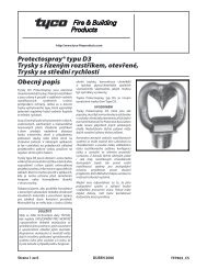
Type D3 Protectospray® Ugello a spruzzo direzionale, Tipo aperto ...
Type D3 Protectospray® Ugello a spruzzo direzionale, Tipo aperto ...
Type D3 Protectospray® Ugello a spruzzo direzionale, Tipo aperto ...

You also want an ePaper? Increase the reach of your titles
YUMPU automatically turns print PDFs into web optimized ePapers that Google loves.
Technical Services: Tel: http://www.tyco-fireproducts.com<br />
(800) 381-9312 / Fax: (800) 791-5500<br />
<strong>Type</strong> <strong>D3</strong> Protectospray ®<br />
<strong>Type</strong> <strong>D3</strong> <strong>Protectospray®</strong><br />
<strong>Ugello</strong> Directional a <strong>spruzzo</strong> Spray<strong>direzionale</strong>, Nozzles, Open, <strong>Tipo</strong> <strong>aperto</strong>,<br />
Velocità Medium media Velocity<br />
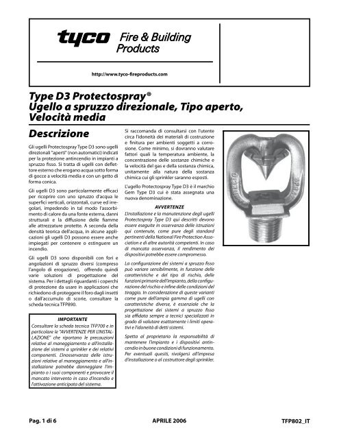
Descrizione<br />
General<br />
Description<br />
Gli ugelli Protectospray <strong>Type</strong> <strong>D3</strong> sono ugelli<br />
direzionali "aperti" (non automatici) indicati<br />
per Thela <strong>Type</strong> protezione <strong>D3</strong> Protectospray antincendio in impianti Nozzlesa<br />
<strong>spruzzo</strong> are open fisso. (non-automatic) Si tratta di ugelli directional<br />
con deflettore<br />
spray esterno nozzles che erogano and they acqua are sotto designed forma<br />
di for gocce use in a velocità water spray media fixed e con systems un getto for di<br />
forma<br />
fire protection<br />
conica.<br />
applications. They are<br />
external deflector type nozzles that<br />
Gli discharge ugelli <strong>D3</strong> asono uniformly particolarmente filled cone efficaci of<br />
per medium ricoprire velocity con uno water <strong>spruzzo</strong> droplets. d'acqua le<br />
superfici The <strong>D3</strong> verticali, Nozzles orizzontali, are effective curve in cover- ed irregolari,ing<br />
exposed impedendo vertical, in tal modo horizontal, l'assorbimento<br />
curved, di and calore irregular da una fonte shaped esterna, surfaces danni<br />
strutturali in a cooling e spray la diffusione to prevent delle excessive fiamme<br />
alle absorption attrezzature of heat protette. from an A seconda externaldella fire<br />
densità<br />
and possible<br />
teorica dell'acqua,<br />
structural<br />
in<br />
damage<br />
alcune appli-<br />
or<br />
spread of fire to the protected equipcazioni<br />
gli ugelli <strong>D3</strong> possono essere anche<br />
ment. In some applications, depending<br />
impiegati<br />
on water design<br />
per contenere<br />
density<br />
o<br />
requirements,<br />
estinguere un<br />
incendio. the <strong>Type</strong> <strong>D3</strong> Nozzles may also be used<br />
Gli<br />
for<br />
ugelli<br />
fire control<br />
<strong>D3</strong> sono<br />
or extinguishment.<br />
disponibili con fori e<br />
angolazioni The <strong>Type</strong> <strong>D3</strong> di Nozzles <strong>spruzzo</strong> diversi are available (compreso in<br />
l'angolo a wide di variety erogazione), of orifice offrendo sizesquindi and<br />
varie spray soluzioni angles (included di progettazione angle of dis- del<br />
sistema. charge) Per to provide i dettagli versatility riguardanti ini system coperchi<br />
di<br />
design.<br />
protezione<br />
Refer<br />
da<br />
to<br />
usare<br />
Technical<br />
in applicazioni<br />
Data Sheet<br />
che<br />
TFP890 for information on Blow-Off<br />
richiedono<br />
Plugs that<br />
di<br />
can<br />
proteggere<br />
be used<br />
il<br />
for<br />
foro<br />
applications<br />
dagli insetti<br />
o where dall'accumulo protectiondi isscorie, required consultare against la<br />
scheda insect tecnica infestation TFP890. or accumulation of<br />
debris within the nozzle orifice.<br />
It is recommended IMPORTANTE that the end user be<br />
consulted Consultare with la scheda respect tecnica to the TFP700 suitability e in<br />
of<br />
particolare<br />
the materials<br />
le "AVVERTENZE<br />
of construction<br />
PER L'INSTALand<br />
LAZIONE" che riportano le precauzioni<br />
relative al maneggiamento e all'installazione<br />
dei sistemi IMPORTANT<br />
a sprinkler e dei relativi<br />
componenti.<br />
Always refer<br />
L'inosservanza<br />
to Technical<br />
delle<br />
Data<br />
istru-<br />
Sheet TFP700 for the “INSTALLER<br />
zioni<br />
WARNING”<br />
relative al<br />
that<br />
maneggiamento<br />
provides cautions<br />
e all'installazione<br />
with respect potrebbe to handling danneggiare and install'impiantolation o ofi suoi sprinkler componenti systems e provocare and comil<br />
mancato ponents. intervento Improperin handling caso d'incendio and ine<br />
l'attivazione stallation can anticipata permanently del sistema.<br />
damage<br />
a sprinkler system or its components<br />
and cause the nozzle to fail to<br />
operate in a fire situation.<br />
Si finish raccomanda for any given di consultarsi corrosive con environ- l'utente<br />
circa ment. l'idoneità The effects dei materiali of ambient di costruzione tempera-<br />
e ture, finitura concentration per ambienti of soggetti chemicals, a corro- and<br />
sione. gas/chemical Come minimo, velocity, si dovranno should be valutare con-<br />
fattori sidered, quali at ala minimum, temperatura along ambiente, with thela<br />
concentrazione corrosive nature delle tosostanze which the chimiche sprin- e<br />
la klers velocità maydel begas exposed. e della sostanza chimica,<br />
unitamente The <strong>Type</strong> <strong>D3</strong> alla Protectospray natura della Nozzle sostanza is<br />
chimica a redesignation cui gli sprinkler for the saranno Gem <strong>Type</strong> esposti. <strong>D3</strong>.<br />
L'ugello Protectospray WARNINGS <strong>Type</strong> <strong>D3</strong> è il marchio<br />
Gem The <strong>Type</strong> <strong>D3</strong> <strong>D3</strong>cui Protectospray è stata assegnata Nozzles una<br />
nuova described denominazione. herein must be installed and<br />
maintained in compliance with this<br />
document, as<br />
AVVERTENZE<br />
well as with the applica-<br />
L'installazione ble standards e la ofmanutenzione the National degli Fire ugelli Pro-<br />
Protectospray tection Association, <strong>Type</strong> <strong>D3</strong> qui in addition descritti devono to the<br />
essere standards eseguite of in any osservanza other authorities delle istruzioni hav-<br />
qui ing contenute, jurisdiction. come Failure pure todegli do standard so may<br />
pertinenti impair the della performance National Fire Protection of theseAsso deciationvices.<br />
e di altre autorità competenti. In caso<br />
di The mancata designosservanza, of individual il rendimento water spray dei<br />
dispositivi fixed systems potrebbe can essere vary compromesso. considerably,<br />
depending on the characteristics and<br />
La nature configurazione of the hazard, dei sistemi thea <strong>spruzzo</strong> basic pur- fisso<br />
può pose variare of thesensibilmente, spraying system, in funzione the con- delle<br />
caratteristiche figuration of the e del hazard, tipo di andrischio, wind/draft delle<br />
funzioni conditions. primarie Because dell'impianto, of della these configuvarirazioneations del asrischio well e as infine thedelle wide condizioni range del of<br />
tiraggio. available In considerazione nozzle spray di characteristics,<br />
queste varianti<br />
come<br />
the design<br />
pure dell'ampia<br />
of water<br />
gamma<br />
spray<br />
di<br />
fixed<br />
ugelli<br />
sys-<br />
con<br />
tems for fire protection must only be<br />
caratteristiche<br />
performed by<br />
diverse,<br />
experienced<br />
è essenziale<br />
designers<br />
che la<br />
progettazione who thoroughly dei understand sistemi a <strong>spruzzo</strong> the limita- fisso<br />
sia tions affidata as well sempre as a capabilities tecnici specializzati of suchin<br />
grado systems. di valutare esattamente i limiti operativi<br />
e l'idoneità di detti sistemi.<br />
The owner is responsible for maintain-<br />
Spetta ing their al proprietario fire protection la system responsabilità and dedi<br />
mantenere vices in l'impianto proper operating e i dispositivi condition. antincendio<br />
The in installing buone condizioni contractor di funzionamento.<br />
or sprinkler<br />
Per<br />
manufacturer<br />
eventuali quesiti,<br />
should<br />
rivolgersi<br />
be contacted<br />
all'impresa<br />
with any questions.<br />
d'installazione o al costruttore degli sprinkler.<br />
Pag. di 6 APRILE 2006<br />
TFP802_IT<br />
Page 1 of 6 APRIL, 2006<br />
TFP802
Pag. 2 di 6 TFP802_IT<br />
Page 2 of 6 TFP802<br />
Scheda Technical<br />
Technical tecnica<br />
Certificazioni Data Data<br />
Gli ugelli Protectospray <strong>Type</strong> <strong>D3</strong> con finitura<br />
naturale, Approvals cromati, bronzo con rivestimento<br />
di The piombo natural oppure finish, in acciaio chrome inox, plated, sono listati and<br />
UL lead e C-UL coated ed omologati bronze, FM. as well as stainless<br />
steel <strong>Type</strong> <strong>D3</strong> Protectospray Noz-<br />
Pressione zles are UL di esercizio and C-UL massima Listed, as well<br />
175 as FM psi (12,1 Approved. bar). Vedi anche Fig. 2, Nota 2.<br />
Maximum Working Pressure<br />
Coefficiente<br />
175 psi (12,1<br />
di<br />
bar).<br />
scarico<br />
Consultare Also refer referla to toTabella Figure A. 2, Note 2.<br />
Angoli Discharge di <strong>spruzzo</strong> Coefficient<br />
Consultare Refer to Table la Tabella A. B.<br />
Finitura<br />
Spray Angles<br />
e materiali<br />
Consultare<br />
Refer to Table<br />
la Tabella<br />
B.<br />
E.<br />
Finish and Material<br />
Filettatura Refer to Table E.<br />
1/2” NPT.<br />
Thread Connection<br />
Costruzione 1/2 inch NPT. (Bronzo)<br />
Corpo Physical della testa Characteristics<br />
. . . . . . . . . . . . . . . . . . . . . . . Bronzo<br />
Deflettore (Bronze) . . . . . . . . . . . . . . . . . . . . . . . . . . . . . . Bronzo<br />
Diffusore Frame . . . . . . . . . . . . . . . . . . . . . . . . . . . . . . . . . . . . . Bronze . . Bronzo<br />
Perno Deflector . . . . . . . . . . . . . . . . . . . . . . . . . . . . . . . . . . . . Bronze . . Bronzo<br />
Splitter . . . . . . . . . . . . Bronze<br />
Costruzione<br />
Pin . . . .<br />
(acciaio<br />
. . . .<br />
inox)<br />
. . . . . . Bronze<br />
Corpo della testa . . . . . . . . . . . . . . . . . . ASTMA-296,<br />
Grade Physical CF-8M Characteristics<br />
(equiv. <strong>Type</strong> 316 S.S)<br />
Deflettore (Stainless . . . . . Steel) . . . . . . . . . . . . . . . . . . . .<strong>Type</strong> 316 S.S<br />
Diffusore Frame . . . . . . . . . . . . . . . . . . . . . . . . . ASTM . . . .<strong>Type</strong> A-296, 316 S.S<br />
Perno Grade . . . . . CF-8M . . . . . . . . . . (equiv.<strong>Type</strong> . . . . . . . . . . . . . .<strong>Type</strong> 316 316 S.S) S.S<br />
Deflector . . . . . . . <strong>Type</strong> 316 S.S<br />
Splitter . . . . . . . . <strong>Type</strong> 316 S.S<br />
Pin . . . . . . . . . . <strong>Type</strong> 316 S.S<br />
Criteri di<br />
progettazione<br />
Design Design<br />
Criteria Criteria<br />
Posizionamento dell’ugello. Nei casi in cui<br />
l'Autorità competente esiga che lo <strong>spruzzo</strong><br />
d'acqua Nozzle sia Placement. diretto su Where tutta la direct superficie im-<br />
protetta, pingement gli ugelli of water dovranno spray essere onto ontointerval all of<br />
lati the thee protected orientati in modo surface che is isla required copertura by del<br />
getto the Authority investa completamente having Jurisdiction, la superficie the<br />
protetta nozzles con are to il valore be spaced minimo and anddi directed densità<br />
media so that richiesto; their spray si raccomanda patterns comunque will com-<br />
di<br />
pletely<br />
intervallare<br />
cover<br />
gli<br />
the<br />
ugelli<br />
plane-of-protection<br />
di 3,7 m (12 ft) nelle<br />
with the minimum required average<br />
installazioni<br />
density; however,<br />
al coperto,<br />
it<br />
e<br />
is<br />
di<br />
recommended<br />
non più di 3,0 m<br />
(10 that ft) indoor nelle installazioni nozzle spacing all'<strong>aperto</strong>. be 12 Nei feet casi<br />
in (3,7 cui m) la configurazione or less and that comprende outdoor nozzle colate<br />
o spacing cadute come be 10 nella feet protezione (3,0 m) di or conteni- less.<br />
tori Where di liquidi rundown secondo lo or orstandard slippage NFPA 15, is<br />
si planned, applicano e.g., le stesse exposure quote protection di intervallo of al<br />
coperto vessels vesselse per all'<strong>aperto</strong>. NFPA 15, the above recommended<br />
indoor and outdoor spac-<br />
Ad ingsingsesempio, also apply. per proteggere le superfici<br />
di un contenitore di liquidi, gli ugelli sono<br />
When used for protecting the surfaces<br />
posizionati<br />
of a vessel,<br />
perpendicolarmente<br />
for example, the<br />
e<br />
nozzles<br />
a circa<br />
0,6 are arem positioned (2 ft) di distanza normal to todalla and superficie. approxi-<br />
Tale mately accorgimento, 2 feet (0,6 abbinato m) from the ad surface. un orientamento<br />
This approach, corretto, in inservirà conjunction ad utilizzare with a ain<br />
maniera properly ottimale selected il getto spray oltre angle, a ridurre will i<br />
disturbi tend to causati make more dalle effective correnti d'aria use of ofe the dal<br />
tiraggio spray as al getto well stesso. as help minimize the<br />
SPRAY ANGLE<br />
(INCLUDED ANGOLO DI SPRUZZO ANGLE<br />
(COMPRESO ANGOLO<br />
DI OF OFSCARICO) DISCHARGE) E MISURA<br />
AND FORO ORIFICE STAMPATI SIZE SU<br />
STAMPED SPIANATURA ON PER<br />
WRENCHING<br />
CHIAVE<br />
AREA<br />
44,5 1-3/4" mm<br />
(44,5 (1-3/4”) mm)<br />
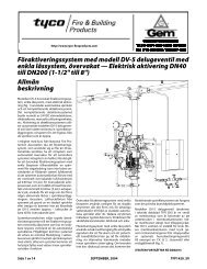
Copertura disturbance del effects getto. of I profili wind/draft delle angoconlazioniditionsditionsdel on getto the water dell'ugello spray patterns. da 65 a 180<br />
gradi Spray sono Patterns. illustrati a The Fig. 2 Design e si riferiscono Spray<br />
a Profiles pressioni for di the scarico nozzle da 20 spray a 60 angles psi (da 1,4 of<br />
a 65 4,1 to tobar). 180 180Se degrees la pressione are shown di scarico in Figure supera<br />
60 2 and psi (4,1 apply bar), to tol'area discharge di copertura pressures risulterà of<br />
inferiore 20 to 60 60in psi quanto (1,4 to toa 4,1 pressioni bar). Discharge elevate il<br />
getto pressures ha tendenza in excess a rientrare. of 60 psi Per (4,1 informa- bar)<br />
zioni<br />
will result<br />
relative<br />
in<br />
a<br />
a<br />
pressioni<br />
decrease<br />
di<br />
in<br />
scarico<br />
coverage<br />
supe-<br />
area since the spray patterns tend to<br />
riori,<br />
draw<br />
rivolgersi<br />
inwards at<br />
al<br />
higher<br />
nostro<br />
pressures.<br />
reparto tecnico.<br />
Re-<br />
Le ferferdistanze inquiries assiali on higher massime discharge consentite pres- tra<br />
la sures punta to todell'ugello the Technical e la superficie Services di proteDezionepartment. sono riportate The alle maximum tabelle C e axial D. Per<br />
una distances distanza between assiale di the 0,9 nozzle m (3 ft) tip tipo and infe-<br />
2-1/16" 52 mm<br />
(52,4 (2-1/16”) mm)<br />
63,5 2-1/2" mm<br />
(63,5 (2-1/2”)<br />
mm)<br />
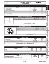
FIGURE FIGURE FIGURA 1 1<br />
TYPE TYPE UGELLI D-3 D-3 PROTECTOSPRAY PROTECTOSPRAY TYPE NOZZLES NOZZLES D-3<br />
NOMINAL NOMINAL QUOTE DIMENSIONS<br />
DIMENSIONS<br />
NOMINALI<br />
PIN PERNO<br />
DEFLECTOR<br />
DEFLETTORE<br />
SPLITTER<br />
DIFFUSORE<br />
SPIANATURA WRENCHING PER<br />
LA AREA CHIAVE<br />
1/2”NPT<br />
1/2" NPT<br />
FRAME CORPO<br />
DELLA<br />
QUOTA NOMINALE 7/16" (11,1 D'INNESTO mm)<br />
NOMINAL 11,1 mm (7/16”) MAKE-IN<br />
TESTA<br />
MISURA ORIFICE FORO DIAMETRO MINIMUM MINIMO<br />
NFPA<br />
K-FACTOR<br />
K-FACTOR<br />
SIZE<br />
DIAMETER<br />
(GPM/psi NFPA<br />
ISO/SI<br />
(GPM ÷ psi) (LPM ÷ bar)<br />
0,5 ISO/SI<br />
) (l/min.bar0,5 )<br />
NO. 16 0,203” (5,16 mm) 1,2 17,3<br />
NO. NO. 18 16 0,250” 0.203" (5,16 (6,35 mm) 1,8 1.2<br />
25,9 17,3<br />
NO. 18<br />
NO. 21<br />
NO. 21<br />
NO. 24<br />
NO. 24<br />
0.250"<br />
0,281”<br />
0.281"<br />
0,328”<br />
0.328"<br />
(6,35 mm)<br />
(7,14 mm)<br />
(7,14 mm)<br />
(8,33 mm)<br />
(8,33 mm)<br />
1.8<br />
2,3<br />
2.3<br />
3,0<br />
3.0<br />
25,9<br />
33,1<br />
33,1<br />
43,2<br />
43,2<br />
NO. NO. 28 28 0,375” 0.375" (9,53 mm) 4,1 4.1<br />
59,0<br />
59,0<br />
NO. NO. 32 32 0,438” 0.438" (11,13 mm) 5,6 5.6<br />
80,6<br />
80,6<br />
NO. NO.<br />
34 34<br />
0,500”<br />
0.500" (12,70<br />
mm)<br />
mm) 7,2<br />
7.2<br />
103,7<br />
103,7<br />
TABELLA TABLE TABLE AA<br />
A<br />
SELECTION SELECTION SELEZIONE OF OFMISURE ORIFICE ORIFICEFORO SIZES SIZES<br />
65°<br />
80°<br />
95°<br />
125°<br />
140°<br />
160°<br />
110° 180°<br />
TABELLA TABLE TABLE B B<br />
SELEZIONE SELECTION SELECTIONANGOLO OF OF SPRAY SPRAY DI SPRUZZO ANGLES ANGLES<br />
riore, plane-of-protection, il profilo dell'angolazione for exposure è identico proproa quello tection, delle are areangolazioni given in Table nominali C da and and65 D. a<br />
140 When gradi. the axial distance from the nozzle<br />
tip to the plane-of-protection is 3<br />
Filtri feet delle (0,6 m) condutture. or less, the La norma Design DesignNFPA Spray 15<br />
prescrive Profile l'installazione is the same samedi as filtri the nelle nominal condutture<br />
spray idriche angles di diametro of 65 thru inferiore 140 degrees. a 9,5 mm<br />
(3/8”), Main Maincioè Pipeline da N. 16 Strainers. a N. 24 (V. Tabella Main A) pipe- che<br />
alimentano line strainers impianti per sprinkler NFPA 15 15con are areugelli, re-<br />
come quired pure for forin systems ogni impianto utilizing in cui nozzles l'acqua<br />
trasporti with a flow scorie. path less than 3/8 inch (9,5<br />
mm) diameter, i.e., No. 16 thru No. 24<br />
(Ref. Table A), and for any system<br />
where the water is likely to contain<br />
obstructive material.
TFP802_IT Pag. di 6<br />
TFP802 Page 3 of 6<br />
AXIAL AXIAL DISTANCE DISTANCE FROM FROM NOZZLE, NOZZLE, FEET FEET<br />
DISTANZA ASSIALE DA UGELLO, FT<br />
RADIAL DISTANCE DISTANCE FROM<br />
DISTANZA RADIALE DA ASSE UGELLO, FT<br />
NOZZLE CENTERLINE, FEET<br />
0<br />
0<br />
2<br />
4<br />
6<br />
8<br />
10<br />
12<br />
14<br />
16 16<br />
2 4 6 8<br />
NOZZLE UGELLO<br />
PROFILO SPRAY<br />
PROFILE<br />
SPRUZZO<br />
ANGOLAZIONE<br />
FIXED ANGLE<br />
FISSA<br />
(ORIENTAMENTO)<br />
(ORIENTATION)<br />
180°<br />
160°<br />
140°<br />
125°<br />
110°<br />
95°<br />
80°<br />
65°<br />
AXIAL AXIAL DISTANCE DISTANCE FROM FROM NOZZLE, NOZZLE, METERS METERS<br />
DISTANZA RADIAL RADIALRADIALE DISTANCE DA ASSE FROM UGELLO,<br />
NOZZLE CENTERLINE, METRI METERS<br />
0 0,5 1,0 1,5 2,0 2,5<br />
0<br />
0,5<br />
1,0<br />
1,5<br />
2,0<br />
2,5<br />
3,0<br />
3,5<br />
4,0<br />
4,5<br />
AXIAL QUOTA DISTANCE ASSIALE<br />
RADIAL DISTANZA<br />
DISTANCE RADIALE<br />
PLANE OF<br />
PIANO DI<br />
PROTECTION<br />
PROTEZIONE<br />
FIGURE FIGURE FIGURA 2 2<br />
DATI WATER WATER TEORICI DISTRIBUTION DISTRIBUTION DI DISTRIBUZIONE DESIGN DESIGN DELL'ACQUA DATA DATA<br />
Installazione<br />
Installation<br />
Installation<br />
65°<br />
GRAVITY<br />
NOTES:<br />
NOTE:<br />
GRAVITÁ<br />
1. 1. Quote Design Designricavate data obtained da test from in ambiente tests in still non air. ventilato.<br />
2. Quote si applicano a valori di pressione residua alla presa dell'ugello compresi tra 1,4 -<br />
2. 4,1 Design bar (20 data datae 60 applies psi). Per to a avalori residual di pressione (flowing) pressure fino a 12,1 range bar (175 at the psi) nozzle rivolgersi inlet al of ofservizio 20 to 60<br />
tecnico psi (1,4 di to toTyco 4,1 bar). Fire & For Building pressures Products. up to 175 psi (12,1 bar) consult Tyco Fire & Building<br />
Per Products i valori Technical minimi di Services. pressione residua ammessi, consultare le autorità competenti.<br />
3. La Refer sagoma to the thee authority il profilo del having getto jurisdiction rimangono for foressenzialmente their minimum required inalterati residual sulla distanza pressures.<br />
assiale massima espressa alle Tabelle C e D.<br />
4. 3. Per The Thedistanze shapes of assiali the Design inferiori Spray a 0,6 m Profiles (2 ft) e remain per gli essentially ugelli con angolo unchanged di <strong>spruzzo</strong> over the da 65°a<br />
140°,<br />
maximum<br />
il profilo<br />
Axial<br />
è<br />
Distances<br />
identico a<br />
shown<br />
quello dell'angolazione<br />
in Tables C and D.<br />
nominale.<br />
5. 4. Le For Fordistanze axial distances assiali massime of 2 feet illustrate (0,6 meters) alle Tabelle and less lessC and e D si for basano nozzle nozzlesulla spray protezione angles of 65° to<br />
all'esposizione<br />
140°, the Design Spray Profile is the same as the nominal spray angle.<br />
5. The maximum Axial Distances shown in Tables C and D are based on exposure<br />
protection.<br />
FIGURA FIGURE FIGURE 3<br />
3<br />
TYPE TYPE CHIAVE W11 W11SPRINKLER SPRINKLER SPRINKLER W-TYPE WRENCH WRENCH 11<br />
DISTANZA ASSIALE DA UGELLO, METRI<br />
180°<br />
160°<br />
140°<br />
125°<br />
110°<br />
95°<br />
80°<br />
L'installazione <strong>Type</strong> <strong>D3</strong> Protectospray degli ugelli Nozzles Protectospray must<br />
<strong>Type</strong> be installed <strong>D3</strong> deve essere in accordance eseguita in with osservanza the fol-<br />
delle<br />
lowing<br />
seguenti<br />
instructions:<br />
istruzioni:<br />
NOTA NOTE NOTE<br />
Applicando<br />
AA leak leak tight tight<br />
la coppia<br />
1/2 1/2 inch inch<br />
di 9,5<br />
NPT NPT<br />
- 19 Nm<br />
nozzle nozzle<br />
(7 to 14<br />
joint joint<br />
ft.<br />
should should be be obtained obtained with with aa torque torque of of 77<br />
lb)<br />
to to<br />
si<br />
14 14<br />
dovrebbe<br />
ft.lbs. ft.lbs.<br />
ottenere<br />
(9,5 (9,5 to to 19,0 19,0<br />
un giunto<br />
Nm). Nm).<br />
1/2"<br />
AA maximaxi- NPT a<br />
perfetta mummum of oftenuta 21 21 ft. ft. . lbs. lbs. Per installare (28,5 (28,5 Nm) Nm) ugelli of of torque torque con un<br />
raccordo may may be be 1/2" used usedNPT to to non install install si dovrebbe nozzles nozzles superare with with 1/2 1/2<br />
la NPT NPT coppia connections. connections. di 29 Nm (20 Higher Higher ft.lb). Una levels levels coppia of of<br />
eccessiva torque torque may may potrebbe distort distort deformare the the nozzle nozzle inlet inlet l'ingresso and and<br />
dell'ugello,<br />
cause cause leakage leakage<br />
provocare<br />
or or<br />
perdite<br />
impairment impairment<br />
e compromet-<br />
of of the the<br />
nozzle. nozzle.<br />
terne il funzionamento.<br />
Step 1. With pipe thread sealant ap-<br />
Step plied to . Applicare the pipe threads, il sigillante hand alla tighten filettatura<br />
the del nozzle tubo into e serrare the nozzle l'ugello fitting. a mano nel<br />
relativo raccordo.<br />
Step 2. Tighten the nozzle into the<br />
Step nozzle 2. fitting Usando using esclusivamente only the W-<strong>Type</strong> l'appo- 11<br />
sita Sprinkler chiave Wrench W-<strong>Type</strong> 11 (Ref. (V. Fig. Figure 3), serrare 3). With Witha<br />
fondo reference l'ugello to Figure nel relativo 1 the theraccordo. W-<strong>Type</strong> W-<strong>Type</strong>Con 11<br />
riferimento<br />
Sprinkler Wrench<br />
a Fig. 1,<br />
is<br />
la<br />
to<br />
chiave<br />
be applied<br />
W-<strong>Type</strong> 11<br />
to<br />
the wrenching area.<br />
deve essere applicata sulla spianatura dello<br />
sprinkler.<br />
Care Care and and<br />
Cura Maintenance<br />
Maintenance<br />
e<br />
manutenzione<br />
The <strong>Type</strong> <strong>D3</strong> Protectospray Nozzles<br />
must be maintained and serviced in<br />
Istruzioni<br />
accordance<br />
per la<br />
with<br />
manutenzione<br />
the following<br />
e la revisione<br />
instruc-<br />
degli tions: ugelli <strong>D3</strong> Protectospray:<br />
NOTA<br />
NOTE NOTE<br />
Prima Before Before di chiudere closing closing la aa fire fire valvola protection protection principale system system di un<br />
impianto main main control control antincendio valve valveper for for svolgere maintenance<br />
maintenance gli interventi<br />
work workdi on onmanutenzione the the fire fire protection protection sul sistema system system control- that that<br />
lato it it controls, controls, dalla valvola permission permission stessa, richiedere to to shut shut down down l'autoriz- the the<br />
zazione affected affected delle fire fireautorità protection protection preposte system system e avvertire must must be beil<br />
personale obtained obtainedche from from potrebbe the the proper proper essere condizionato authorities authorities<br />
da and and questo all all personnel personnel intervento. who who may may be be affected affected<br />
by by this this action action must must be be notified. notified.<br />
Gli ugelli Protectospray <strong>Type</strong> <strong>D3</strong> forniti dalla<br />
<strong>Type</strong> <strong>D3</strong> Protectospray Nozzles must<br />
fabbrica<br />
never be<br />
non<br />
painted,<br />
devono mai<br />
plated,<br />
essere<br />
coated<br />
verniciati,<br />
or<br />
placcati, altered ricoperti in any way o altrimenti after leaving modificati, the<br />
altrimenti factory; otherwise, il rendimento the thepotrebbe spray perform- esserne<br />
compromesso.<br />
ance may be impaired.<br />
Fare Care Careattenzione must be exercised a non danneggiare to avoid damdamgli ugelli age to prima, the nozzles durante - -e before, dopo l'installazione.<br />
during, and<br />
Gli after ugelli installation. che hanno Nozzles subito damaged danni poiché by<br />
caduti<br />
dropping,<br />
accidentalmente,<br />
striking, wrench<br />
colpiti, o<br />
twist/slip-<br />
poiché la<br />
page, or the like, must be replaced.<br />
chiave è slittata o per altro motivo, devono<br />
essere Frequent sostituiti. visual inspections are recommended<br />
to be initially performed for<br />
Completata nozzles installed l'installazione, in potentially nei primi corro- tempi<br />
si sive raccomanda atmospheres di esaminare to verify verifycon the theuna integrity certa<br />
frequenza of the materials gli ugelli of installati construction in ambienti and<br />
potenzialmente finish as they may corrosivi, be affected al fine di by byverifi the<br />
care corrosive l'integrità conditions dei materiali present e della finitura for a<br />
che given potrebbero installation. essere Thereafter, esposti a corrosione. annual<br />
Successivamente,<br />
inspections per NFPA<br />
eseguire<br />
25 are<br />
una<br />
required.<br />
verifica<br />
annua Water Watersecondo spray fixed la norma systems NFPA fo 25. fire proction<br />
service require regularly sched-<br />
I uled sistemi care antincendio and maintenance a getto d'acqua by trained fisso<br />
devono personnel. essere In addition sottoposti to a inspecting interventi<br />
programmati nozzles for proper di manutenzione spray performance<br />
e revisione<br />
da during parte water di personale flow trip tripspecializzato. tests of the Oltre sys-<br />
ad tem, eseguire it is recommended il controllo dell'efficacia that nozzles dello<br />
<strong>spruzzo</strong> be periodically nell'ambito inspected delle prove for broken di portata or<br />
del missing sistema, parts si raccomanda (including di blow-off esaminare plugs gli<br />
where applicable), loading/obstruc-<br />
ugelli periodicamente al fine di rilevare la<br />
tions, or other evidence of impaired<br />
rottura<br />
protection.<br />
o la mancanza<br />
The inspections<br />
di elementi<br />
should<br />
(compresi<br />
be<br />
i tappi scheduled di protezione), weekly carichi or as e frequently ostacoli o altri as<br />
elementi che potrebbero esporli a danni. Le<br />
ispezioni devono (Continued essere programmate on Page Pagecon 6)<br />
(Continua alla pagina 6)
Pag. di 6 TFP802_IT<br />
DISTANZA ASSIALE MASSIMA PER ANGOLO DI SPRUZZO A 65°<br />
ESPRESSO IN FT E INCHES<br />
ANGOLA-<br />
ZIONE FISSA<br />
MISURA FORO<br />
16 18 21 24 28 32 34<br />
0° 10-6 12-6 13-0 13-3 14-6 15-0 15-6<br />
30° 8-3 10-9 10-9 11-9 12-6 13-6 13-9<br />
45° 7-3 10-0 10-0 11-3 11-6 12-6 12-9<br />
60° 6-6 9-3 9-6 10-9 11-0 11-9 12-6<br />
90° 6-0 8-6 9-0 10-3 10-6 10-9 11-6<br />
120° 5-9 7-6 7-6 7-6 8-3 9-0 9-6<br />
135° 5-6 6-0 6-3 6-6 7-0 8-0 8-6<br />
150° 5-3 5-6 5-6 5-9 6-3 7-3 7-6<br />
180° 5-0 5-0 5-0 5-6 5-9 6-6 7-0<br />
DISTANZA ASSIALE MASSIMA PER ANGOLO DI SPRUZZO A 80°<br />
ESPRESSO IN FT E INCHES<br />
ANGOLA-<br />
ZIONE FISSA<br />
MISURA FORO<br />
16 18 21 24 28 32 34<br />
0° 9-0 10-6 11-0 12-0 13-0 14-0 14-0<br />
30° 7-3 8-3 8-9 10-6 11-6 12-3 12-3<br />
45° 6-3 7-6 8-0 10-3 10-6 11-3 11-3<br />
60° 5-6 7-0 7-6 10-0 10-3 10-9 10-9<br />
90° 5-0 6-0 7-0 9-3 9-6 9-9 10-0<br />
120° 4-6 4-9 5-9 6-6 7-3 7-0 8-0<br />
135° 4-3 4-6 5-0 5-6 6-0 6-3 6-9<br />
150° 4-0 4-0 4-6 5-0 5-6 5-6 6-0<br />
180° 3-9 3-9 4-0 4-6 4-9 5-3 5-6<br />
DISTANZA ASSIALE MASSIMA PER ANGOLO DI SPRUZZO A 95°<br />
ESPRESSO IN FT E INCHES<br />
ANGOLA-<br />
ZIONE FISSA<br />
MISURA FORO<br />
16 18 21 24 28 32 34<br />
0° 7-0 7-9 9-6 10-6 11-0 12-0 12-6<br />
30° 5-9 6-6 7-9 9-9 10-6 10-9 11-0<br />
45° 5-3 6-3 7-0 9-6 9-9 10-3 10-3<br />
60° 4-9 6-0 6-9 9-3 9-6 9-9 9-9<br />
90° 4-0 5-0 6-6 8-3 8-6 8-9 8-9<br />
120° 3-6 3-9 5-0 5-3 6-3 6-0 6-6<br />
135° 3-3 3-6 4-0 4-6 5-3 5-3 5-6<br />
150° 3-0 3-0 3-6 4-0 4-6 4-6 4-9<br />
180° 3-0 3-0 3-3 3-9 4-0 4-3 4-6<br />
DISTANZA ASSIALE MASSIMA PER ANGOLO DI SPRUZZO A 110°<br />
ESPRESSO IN FT E INCHES<br />
ANGOLA-<br />
ZIONE FISSA<br />
MISURA FORO<br />
16 18 21 24 28 32 34<br />
0° 6-0 7-0 9-0 9-6 11-0 11-3 11-6<br />
30° 5-3 6-3 7-3 8-9 9-6 9-9 10-0<br />
45° 4-9 5-9 6-6 8-6 9-0 9-0 9-3<br />
60° 4-3 5-6 6-3 8-3 8-6 8-6 8-9<br />
90° 3-6 4-6 5-9 7-6 7-6 7-6 7-9<br />
120° 2-9 3-3 4-6 4-6 5-6 5-6 5-6<br />
135° 2-6 2-9 3-6 3-6 4-6 4-6 4-9<br />
150° 2-3 2-6 3-0 3-3 3-6 3-9 4-3<br />
180° 2-3 2-3 2-9 3-0 3-3 3-6 3-9<br />
DISTANZA ASSIALE MASSIMA PER ANGOLO DI SPRUZZO A 125°<br />
ESPRESSO IN FT E INCHES<br />
ANGOLA-<br />
ZIONE FISSA<br />
MISURA FORO<br />
16 18 21 24 28 32 34<br />
0° 4-6 5-0 6-6 7-9 10-0 10-3 10-6<br />
30° 3-9 3-9 6-3 6-9 8-6 8-6 8-9<br />
45° 3-0 3-6 5-9 6-0 7-9 7-6 8-3<br />
60° 2-6 3-0 5-6 5-9 7-3 7-3 7-9<br />
90° 2-0 2-9 4-9 5-0 5-9 6-0 6-6<br />
120° 1-9 2-3 3-3 3-3 3-9 3-9 4-6<br />
135° 1-6 1-9 2-6 2-6 3-3 3-3 3-9<br />
150° 1-6 1-6 2-0 2-3 2-6 2-9 3-6<br />
180° 1-3 1-3 1-9 2-0 2-3 2-6 3-3<br />
DISTANZA ASSIALE MASSIMA PER ANGOLO DI SPRUZZO A 140°<br />
ESPRESSO IN FT E INCHES<br />
ANGOLA-<br />
ZIONE FISSA<br />
MISURA FORO<br />
16 18 21 24 28 32 34<br />
0° 4-0 4-6 6-0 6-6 8-0 8-0 8-0<br />
30° 3-3 3-6 5-6 5-6 6-3 7-0 7-0<br />
45° 2-9 2-9 5-0 5-0 5-6 6-6 6-6<br />
60° 2-3 2-6 4-6 4-6 5-3 5-6 5-9<br />
90° 1-9 2-3 4-0 4-0 4-6 4-6 5-0<br />
120° 1-6 1-9 2-3 2-6 2-6 3-0 3-6<br />
135° 1-3 1-6 1-6 1-9 2-0 2-6 2-9<br />
150° 1-3 1-3 1-6 1-6 1-9 2-3 2-6<br />
180° 1-0 1-0 1-3 1-3 1-6 2-0 2-3<br />
DISTANZA ASSIALE MASSIMA PER ANGOLO DI SPRUZZO A 160°<br />
ESPRESSO IN FT E INCHES<br />
ANGOLA-<br />
ZIONE FISSA<br />
MISURA FORO<br />
16 18 21 24 28 32 34<br />
0° 3-6 3-9 4-9 5-0 6-0 6-9 7-0<br />
30° 2-9 3-0 4-3 4-6 5-0 5-9 6-3<br />
45° 2-3 2-6 3-9 4-0 4-6 5-3 5-6<br />
60° 1-9 2-3 3-6 3-9 4-3 4-9 5-3<br />
90° 1-3 1-9 3-0 3-3 3-6 3-9 4-3<br />
120° 1-0 1-3 1-6 2-0 2-0 2-3 2-6<br />
135° 1-0 1-0 1-3 1-3 1-6 1-9 2-0<br />
150° 0-9 0-9 1-0 1-0 1-6 1-6 1-9<br />
180° 0-9 0-9 0-9 0-9 1-3 1-6 1-6<br />
DISTANZA ASSIALE MASSIMA PER ANGOLO DI SPRUZZO A 180°<br />
ESPRESSO IN FT E INCHES<br />
ANGOLA-<br />
ZIONE FISSA<br />
MISURA FORO<br />
16 18 21 24 28 32 34<br />
0° 2-9 3-0 3-6 3-6 4-0 6-0 6-0<br />
30° 2-3 2-3 3-6 3-6 3-9 5-0 5-0<br />
45° 1-9 2-0 3-3 3-3 3-6 4-3 4-3<br />
60° 1-6 1-9 2-9 2-9 3-3 3-9 3-9<br />
90° 1-0 1-6 2-0 2-0 2-6 3-0 3-0<br />
120° 0-9 1-0 1-0 1-0 1-6 1-6 1-6<br />
135° 0-6 0-9 0-9 0-9 1-3 1-3 1-3<br />
150° 0-6 0-6 0-6 0-6 1-0 1-0 1-0<br />
180° 0-6 0-6 0-6 0-6 0-9 0-9 0-9<br />
TABELLA C<br />
DISTANZA ASSIALE MASSIMA TRA ESTREMITÁ UGELLO E SUPERFICIE DI PROTEZIONE<br />
- FT E INCHES -
TFP802_IT Pag. di 6<br />
DISTANZA ASSIALE MASSIMA PER ANGOLO DI SPRUZZO A 65°<br />
IN METRI<br />
ANGOLA-<br />
ZIONE FISSA<br />
MISURA FORO<br />
16 18 21 24 28 32 34<br />
0° 3,2 3,8 4,0 4,0 4,4 4,6 4,7<br />
30° 2,5 3,3 3,3 3,6 3,8 4,1 4,2<br />
45° 2,2 3,0 3,0 3,4 3,5 3,8 3,9<br />
60° 2,0 2,8 2,9 3,3 3,4 3,6 3,8<br />
90° 1,8 2,6 2,7 3,1 3,2 3,3 3,5<br />
120° 1,8 2,3 2,3 2,3 2,5 2,7 2,9<br />
135° 1,7 1,8 1,9 2,0 2,1 2,4 2,6<br />
150° 1,6 1,7 1,7 1,9 1,9 2,2 2,3<br />
180° 1,5 1,5 1,5 1,7 1,8 2,0 2,1<br />
DISTANZA ASSIALE MASSIMA PER ANGOLO DI SPRUZZO A 80°<br />
IN METRI<br />
ANGOLA-<br />
ZIONE FISSA<br />
MISURA FORO<br />
16 18 21 24 28 32 34<br />
0° 2,7 3,2 3,4 3,7 4,0 4,3 4,3<br />
30° 2,2 2,5 2,7 3,2 3,5 3,7 3,7<br />
45° 1,9 2,3 2,4 3,1 3,2 3,4 3,4<br />
60° 1,7 2,1 2,3 3,0 3,1 3,3 3,3<br />
90° 1,5 1,8 2,1 2,8 2,9 3,0 3,0<br />
120° 1,4 1,4 1,8 2,0 2,2 2,1 2,4<br />
135° 1,3 1,4 1,5 1,7 1,8 1,9 2,1<br />
150° 1,2 1,2 1,4 1,5 1,7 1,7 1,8<br />
180° 1,1 1,1 1,2 1,4 1,4 1,6 1,7<br />
DISTANZA ASSIALE MASSIMA PER ANGOLO DI SPRUZZO A 95°<br />
IN METRI<br />
ANGOLA-<br />
ZIONE FISSA<br />
MISURA FORO<br />
16 18 21 24 28 32 34<br />
0° 2,1 2,4 2,9 3,2 3,4 3,7 3,8<br />
30° 1,8 2,0 2,4 3,0 3,2 3,3 3,4<br />
45° 1,6 1,9 2,1 2,9 3,0 3,1 3,1<br />
60° 1,4 1,8 2,1 2,8 2,9 3,0 3,0<br />
90° 1,2 1,5 2,0 2,5 2,6 2,7 2,7<br />
120° 1,1 1,1 1,5 1,6 1,9 1,8 2,0<br />
135° 1,0 1,1 1,2 1,4 1,6 1,6 1,7<br />
150° 0,9 0,9 1,1 1,2 1,4 1,4 1,4<br />
180° 0,9 0,9 1,1 1,1 1,2 1,3 1,4<br />
DISTANZA ASSIALE MASSIMA PER ANGOLO DI SPRUZZO A 110°<br />
IN METRI<br />
ANGOLA-<br />
ZIONE FISSA<br />
MISURA FORO<br />
16 18 21 24 28 32 34<br />
0° 1,8 2,1 2,7 2,9 3,4 3,4 3,5<br />
30° 1,6 1,9 2,2 2,7 2,9 3,0 3,0<br />
45° 1,4 1,8 2,0 2,6 2,7 2,7 2,8<br />
60° 1,3 1,7 1,9 2,5 2,6 2,6 2,7<br />
90° 1,1 1,4 1,8 2,3 2,3 2,3 2,4<br />
120° 0,8 1,0 1,4 1,4 1,7 1,7 1,7<br />
135° 0,8 0,8 1,1 1,1 1,4 1,4 1,4<br />
150° 0,7 0,8 0,9 1,0 1,1 1,1 1,3<br />
180° 0,7 0,7 0,8 0,9 1,0 1,1 1,1<br />
DISTANZA ASSIALE MASSIMA PER ANGOLO DI SPRUZZO A 125°<br />
IN METRI<br />
ANGOLA-<br />
ZIONE FISSA<br />
MISURA FORO<br />
16 18 21 24 28 32 34<br />
0° 1,4 1,5 2,0 2,4 3,0 3,1 3,2<br />
30° 1,1 1,1 1,9 2,1 2,6 2,6 2,7<br />
45° 0,9 1,1 1,8 1,8 2,4 2,3 2,5<br />
60° 0,8 0,9 1,7 1,8 2,2 2,2 2,4<br />
90° 0,6 0,8 1,4 1,5 1,8 1,8 2,0<br />
120° 0,5 0,7 1,0 1,0 1,1 1,1 1,4<br />
135° 0,5 0,5 0,8 0,8 1,0 1,0 1,1<br />
150° 0,5 0,5 0,6 0,7 0,8 0,8 1,1<br />
180° 0,4 0,4 0,5 0,6 0,7 0,8 1,0<br />
DISTANZA ASSIALE MASSIMA PER ANGOLO DI SPRUZZO A 140°<br />
IN METRI<br />
ANGOLA-<br />
ZIONE FISSA<br />
MISURA FORO<br />
16 18 21 24 28 32 34<br />
0° 1,2 1,4 1,8 2,0 2,4 2,4 2,4<br />
30° 1,0 1,1 1,7 1,7 1,9 2,1 2,1<br />
45° 0,8 0,8 1,5 1,5 1,7 2,0 2,0<br />
60° 0,7 0,8 1,4 1,4 1,6 1,7 1,8<br />
90° 0,5 0,7 1,2 1,2 1,4 1,4 1,5<br />
120° 0,5 0,5 0,7 0,8 0,8 0,9 1,1<br />
135° 0,4 0,5 0,5 0,5 0,6 0,8 0,8<br />
150° 0,4 0,4 0,5 0,5 0,5 0,7 0,8<br />
180° 0,3 0,3 0,4 0,4 0,5 0,6 0,7<br />
DISTANZA ASSIALE MASSIMA PER ANGOLO DI SPRUZZO A 160°<br />
IN METRI<br />
ANGOLA-<br />
ZIONE FISSA<br />
MISURA FORO<br />
16 18 21 24 28 32 34<br />
0° 1,1 1,1 1,4 1,5 1,8 2,1 2,1<br />
30° 0,8 0,9 1,3 1,4 1,5 1,8 1,9<br />
45° 0,7 0,8 1,1 1,2 1,4 1,6 1,7<br />
60° 0,5 0,7 1,1 1,1 1,3 1,4 1,6<br />
90° 0,4 0,5 0,9 1,0 1,1 1,1 1,3<br />
120° 0,3 0,4 0,5 0,6 0,6 0,7 0,8<br />
135° 0,3 0,3 0,4 0,4 0,5 0,5 0,6<br />
150° 0,2 0,2 0,3 0,3 0,5 0,5 0,5<br />
180° 0,2 0,2 0,2 0,2 0,4 0,5 0,5<br />
DISTANZA ASSIALE MASSIMA PER ANGOLO DI SPRUZZO A 180°<br />
IN METRI<br />
ANGOLA-<br />
ZIONE FISSA<br />
MISURA FORO<br />
16 18 21 24 28 32 34<br />
0° 0,8 0,9 1,1 1,1 1,2 1,8 1,8<br />
30° 0,7 0,7 1,1 1,1 1,1 1,5 1,5<br />
45° 0,5 0,6 1,0 1,0 1,1 1,3 1,3<br />
60° 0,5 0,5 0,8 0,8 1,0 1,1 1,1<br />
90° 0,3 0,5 0,6 0,6 0,8 0,9 0,9<br />
120° 0,2 0,3 0,3 0,3 0,5 0,5 0,5<br />
135° 0,2 0,2 0,2 0,2 0,4 0,4 0,4<br />
150° 0,2 0,2 0,2 0,2 0,3 0,3 0,3<br />
180° 0,2 0,2 0,2 0,2 0,2 0,2 0,2<br />
TABELLA D<br />
DISTANZA ASSIALE MASSIMA TRA ESTREMITÁ UGELLO E SUPERFICIE DI PROTEZIONE<br />
- METRI -
Pag. 6 di 6 TFP802_IT<br />
NUM. COD. 49 — 3XX — X — XXX<br />
16<br />
MISURA<br />
FORO<br />
N. 16<br />
18 N. 18<br />
21 N. 21<br />
24 N. 24<br />
28 N. 28<br />
32 N. 32<br />
34 N. 34<br />
frequenza settimanale o in funzione delle<br />
particolari circostanze; interventi correttivi<br />
devono essere presi per garantire il funzionamento<br />
degli ugelli in caso d'incendio.<br />
Per le installazioni soggette al gelo e che<br />
incorporano i tappi di protezione, l'opera di<br />
ispezione programmata deve comprendere<br />
la verifica che la condensa non sia gelata<br />
e possa ostacolare il rilascio dei tappi di<br />
protezione.<br />
Spetta al proprietario la responsabilità di<br />
eseguire gli interventi di ispezione, test e<br />
manutenzione dei sistemi e dei dispositivi<br />
antincendio in osservanza delle istruzioni<br />
contenute nel presente documento come<br />
pure degli standard pertinenti prescritti<br />
dalla National Fire Protection Association (V.<br />
NFPA 25) e da altre autorità competenti. Per<br />
eventuali quesiti, rivolgersi all'impresa d'installazione<br />
o al costruttore dello sprinkler.<br />
Si raccomanda di affidare gli interventi di<br />
ispezione, test e manutenzione dei sistemi<br />
a getto d'acqua fisso a un'impresa specializzata,<br />
in conformità alla normativa locale<br />
e/o nazionale.<br />
Garanzia<br />
limitata<br />
Gli articoli prodotti da Tyco Fire & Building<br />
Products (TFBP) sono coperti da una<br />
garanzia di dieci anni (10), concessa esclusivamente<br />
al primo acquirente, da difetti<br />
di produzione e di fabbricazione, purché<br />
pagati, installati e mantenuti in condizioni<br />
d'uso e di servizio normali. La garanzia<br />
scade al decorrere di dieci anni (10) dalla<br />
data di consegna da TFBP. La garanzia non<br />
FINITURA E MATERIALI<br />
1 FINITURA NATURALE BRONZO<br />
4 BRONZO RIVESTITO TEFLON<br />
7 BRONZO RIVESTITO DI PIOMBO<br />
9 BRONZO CROMATO<br />
0 ACCIAIO INOX FINITURA NATURALE<br />
TABELLA E<br />
SELEZIONE DEL NUM. CODICE<br />
è estesa ad articoli e componenti prodotti<br />
da società non associate a TFBP o ad articoli<br />
e componenti soggetti ad abuso, erroneamente<br />
installati, esposti a corrosione o la<br />
cui installazione, manutenzione, modifica<br />
e riparazione non siano state eseguite in<br />
conformità alle norme pertinenti prescritte<br />
dalla "National Fire Protection Association"<br />
o da altre autorità competenti. I materiali<br />
considerati difettosi da TFBP saranno<br />
riparati o sostituiti a sola discrezione di<br />
TFBP. TFBP non si assume e non autorizza<br />
altre persone ad assumersi alcuna responsabilità<br />
in relazione alla vendita dei suoi<br />
prodotti o dei componenti di tali prodotti.<br />
TFBP declina ogni responsabilità per gli<br />
errori di progettazione degli sprinkler o per<br />
le informazioni inaccurate o incomplete<br />
fornite dall'acquirente o dai rappresentanti<br />
dell'acquirente.<br />
In nessun caso TFBP sarà ritenuta responsabile,<br />
per contratto, illeciti civili o responsabilità<br />
oggettiva o in virtú di qualunque<br />
altro criterio legale, per danni incidentali,<br />
indiretti, speciali o consequenziali, tra cui,<br />
ma non limitatamente, le spese di manodopera,<br />
a prescindere dal fatto che TFBP<br />
sia stata informata della possibilità di tali<br />
danni. In nessun caso la responsabilità di<br />
TFBP sarà superiore al prezzo di vendita del<br />
prodotto.<br />
La presente garanzia sostituisce qualunque<br />
altra garanzia espressa o implicita, tra cui le<br />
garanzie di commerciabilità e di idoneità ad<br />
uno scopo particolare.<br />
La presente garanzia limitata espone i<br />
reclami basati su guasti o difetti degli<br />
articoli, materiali o componenti, indipendentemente<br />
dal fatto che il reclamo<br />
065<br />
ANGOLO DI<br />
SPRUZZO<br />
65º<br />
080 80º<br />
095 95º<br />
110 110º<br />
125 125º<br />
140 140º<br />
160 160º<br />
180 180º<br />
stesso sia fondato su contratto, illeciti civili<br />
o responsabilità oggettiva o in virtú di<br />
qualunque altro criterio legale.<br />
La presente garanzia sarà applicata a tutte<br />
le categorie previste dalla legge. L'illegimità,<br />
sia pure parziale, di una sezione della<br />
presente garanzia non annullerà le rimanenti<br />
sezioni.<br />
Procedura di<br />
ordinazione<br />
Indicare il nome completo e il numero di<br />
codice del prodotto all'atto dell'ordinazione.<br />
Per conoscere la disponibilità dei prodotti<br />
contattare il distributore locale.<br />
Ugelli Protectospray D :<br />
Specificare: No. foro (specificare), <strong>Ugello</strong><br />
Protectospray <strong>Type</strong> <strong>D3</strong> con (specificare<br />
finitura / rivestimento e materiale ) con<br />
angolazione di getto (specificare numero),<br />
Num. Cod. (specificare da Tabella E).<br />
Chiave per sprinkler<br />
Specificare: Chiave <strong>Type</strong> W11 Cod. Num. 56-<br />
452-1-001.<br />
Tappi protettivi (optional):<br />
Specificare: <strong>Tipo</strong> di tappo protettivo (specificare<br />
lettera), N. Cod. (specificare da Fig. 1).<br />
(No. 16) Modello A. . . . . . . . N. Cod. 56-320-1-001<br />
(No. 18) Modello K . . . . . . . . N. Cod. 56-320-1-009<br />
(No. 21) Modello J . . . . . . . . N. Cod. 56-320-1-008<br />
(No. 24) Modello I. . . . . . . . . N. Cod. 56-320-1-007<br />
(No. 28) Modello H. . . . . . . . N. Cod. 56-320-1-006<br />
(No. 32) Modello E . . . . . . . . N. Cod. 56-320-1-005<br />
(No. 34) Modello D. . . . . . . . N. Cod. 56-320-1-004<br />
Nota: il presente documento è una traduzione. Le traduzioni di tutti i materiali in lingue diverse dall’inglese sono fatte esclusivamente ad uso dei lettori che non conoscono l’inglese. Non viene fornita alcuna<br />
garanzia, esplicita o implicita, sull’accuratezza delle traduzioni. Per qualsiasi chiarimento riguardante la precisione delle informazioni contenute nella traduzione, si prega di consultare la versione originale in<br />
lingua inglese TFP802 che costituisce la versione ufficiale del documento. Eventuali discrepanze o differenze riscontrate nella traduzione non sono da considerare vincolanti e non hanno alcuna efficacia legale<br />
per eventuali inosservanze, esecuzioni o altro fine. www.quicksilvertranslate.com.<br />
TYCO FIRE & BUILDING PRODUCTS, North Cannon Avenue, Lansdale, Pennsylvania 9 6