

Progetto di un capacimetro a microcontrollore per fotodiodi SPAD
Progetto di un capacimetro a microcontrollore per fotodiodi SPAD
Progetto di un capacimetro a microcontrollore per fotodiodi SPAD

You also want an ePaper? Increase the reach of your titles
YUMPU automatically turns print PDFs into web optimized ePapers that Google loves.
CAPITOLO 3. <strong>SPAD</strong>CAPMETER<br />
<strong>di</strong>gitale. Per avere <strong>un</strong> miglior controllo sul <strong>di</strong>spositivo si è scelto <strong>di</strong> utilizzare <strong>un</strong><br />
clock esterno.<br />
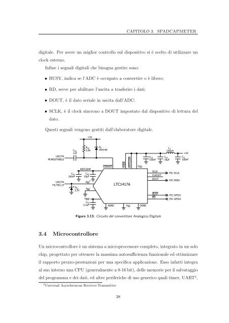
Infine i segnali <strong>di</strong>gitali che bisogna gestire sono:<br />
BUSY, in<strong>di</strong>ca se l’ADC è occupato a convertire o è libero;<br />
RD, serve <strong>per</strong> abilitare l’uscita a trasferire i dati;<br />
DOUT, è il dato seriale in uscita dall’ADC;<br />
SCLK, è il clock sincrono a DOUT impostato dal <strong>di</strong>spositivo <strong>di</strong> lettura del<br />
dato.<br />
Questi segnali vengono gestiti dall’elaboratore <strong>di</strong>gitale.<br />
USCITA<br />
MONOSTABILE<br />
USCITA<br />
FILTRO LP<br />
CS2 1nF<br />
CR1 100nF<br />
DZ1 3,3V<br />
RS2 5,6k<br />
REFCOMP<br />
VREF<br />
+5V<br />
CR2 10μF<br />
AIN +<br />
IN – A<br />
CR3 2,2μF<br />
3.4 Microcontrollore<br />
D2 1N4148<br />
CONVST<br />
AGND<br />
SHDN<br />
EXTCLKIN<br />
LTC1417A<br />
VSS<br />
VDD<br />
DGND<br />
CC3 100nF<br />
SCLK<br />
CLKOUT<br />
DOUT<br />
BUSY<br />
RD<br />
Figura 3.13: Circuito del convertitore Analogico/Digitale<br />
L C<br />
100μH<br />
CC2 10μF<br />
PIC SCLK<br />
PIC MISO<br />
PIC GPIO1<br />
PIC GPIO2<br />
Un <strong>microcontrollore</strong> è <strong>un</strong> sistema a microprocessore completo, integrato in <strong>un</strong> solo<br />
chip, progettato <strong>per</strong> ottenere la massima autosufficienza f<strong>un</strong>zionale ed ottimizzare<br />
il rapporto prezzo-prestazioni <strong>per</strong> <strong>un</strong>a specifica applicazione. Esso infatti integra<br />
al suo interno <strong>un</strong>a CPU (generalmente a 8-16 bit), delle memorie <strong>per</strong> il salvataggio<br />
del programma e dei dati, ed altre <strong>per</strong>iferiche <strong>di</strong> uso generico quali timer, UART 2 ,<br />
2 Universal Asynchronous Receiver-Transmitter<br />
38<br />
+5V<br />
CC1 100nF