

Progetto di un capacimetro a microcontrollore per fotodiodi SPAD
Progetto di un capacimetro a microcontrollore per fotodiodi SPAD
Progetto di un capacimetro a microcontrollore per fotodiodi SPAD

Create successful ePaper yourself
Turn your PDF publications into a flip-book with our unique Google optimized e-Paper software.
InizializeSystem<br />
CAPITOLO 4. SOFTWARE<br />
La f<strong>un</strong>zione InitializeSystem() richiama al suo interno USBDeviceInit() e UserInit();<br />
la prima è <strong>un</strong>a f<strong>un</strong>zione inclusa nel pacchetto Microchip <strong>per</strong> la gestione dell’USB e<br />
<strong>per</strong>mette, come anticipato, <strong>di</strong> configurare il blocco hardware USB <strong>per</strong> la corretta<br />
ricezione/trasmissione dei dati. La seconda invece è riportata in 4.2.<br />
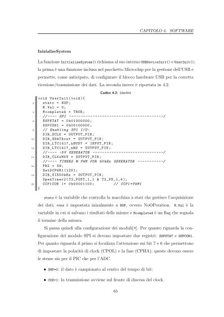
Co<strong>di</strong>ce 4.2: UserInit<br />
void UserInit ( void ){<br />
2 stato = NOP ;<br />
M. Val = 0;<br />
4 Mcompleted = TRUE ;<br />
// ---- SPI ----------------------------------------/<br />
6 SSPSTAT = 0 b01000000 ;<br />
SSPCON1 = 0 b00100000 ;<br />
8 // Enabling SPI I/O:<br />
DIR_SCLK = OUTPUT_PIN ;<br />
10 DIR_SDATAout = OUTPUT_PIN ;<br />
DIR_LTC1417_nBUSY = INPUT_PIN ;<br />
12 DIR_LTC1417_nRD = OUTPUT_PIN ;<br />
// ---- -5V GENERATOR ------------------------------/<br />
14 DIR_CLKxM5V = OUTPUT_PIN ;<br />
// ---- TIMER2 & PWM FOR 50 kHz GENERATOR -----------/<br />
16 PR2 = 59;<br />
SetDCPWM1 (120);<br />
18 DIR_SIN50kHz = OUTPUT_PIN ;<br />
OpenTimer2 ( T2_POST_1_1 & T2_PS_1_4 );<br />
20 CCP1CON |= 0 b00001100 ; // CCP1 = PWM1<br />
}<br />
stato è la variabile che controlla la macchina a stati che gestisce l’acquisizione<br />
dei dati; essa è impostata inizalmente a NOP, ovvero NoOPeration. M.Val è la<br />
variabile in cui si salvano i risultati delle misure e Mcompleted è <strong>un</strong> flag che segnala<br />
il termine della misura.<br />
Si passa quin<strong>di</strong> alla configurazione dei moduli[8]. Per quanto riguarda la con-<br />
figurazione del modulo SPI si devono impostare due registri: SSPSTAT e SSPCON1.<br />
Per quanto riguarda il primo si focalizza l’attenzione sui bit 7 e 6 che <strong>per</strong>mettono<br />
<strong>di</strong> impostare la polarità <strong>di</strong> clock (CPOL) e la fase (CPHA); queste devono essere<br />
le stesse sia <strong>per</strong> il PIC che <strong>per</strong> l’ADC.<br />
SMP=0: il dato è campionato al centro del tempo <strong>di</strong> bit;<br />
CKE=1: la trasmissione avviene sul fronte <strong>di</strong> <strong>di</strong>scesa del clock.<br />
65