TS 100 R Manuel d'utilisation et d'entretien Operator's ... - Husqvarna
TS 100 R Manuel d'utilisation et d'entretien Operator's ... - Husqvarna
TS 100 R Manuel d'utilisation et d'entretien Operator's ... - Husqvarna

Create successful ePaper yourself
Turn your PDF publications into a flip-book with our unique Google optimized e-Paper software.
English<br />
24<br />
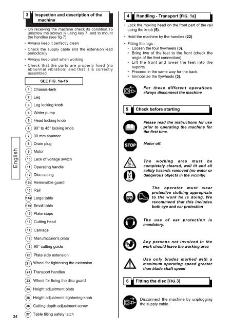
3 Inspection and description of the<br />
machine<br />
• On receiving the machine check its condition.To<br />
unscrew the screws K using key 7, and to mount<br />
the handles (see fig 7)<br />
• Always keep it perfectly clean<br />
• Check the supply cable and the extension lead<br />
periodically<br />
• Always keep alert when working<br />
• Check that the parts are properly fixed (no<br />
abnormal vibration) and that it is correctly<br />
assembled.<br />
1<br />
2<br />
3<br />
4<br />
5<br />
6<br />
7<br />
8<br />
9<br />
10<br />
11<br />
12<br />
12b<br />
13<br />
14a<br />
15<br />
16<br />
17<br />
18<br />
19<br />
20<br />
21<br />
22<br />
23<br />
24<br />
25<br />
26<br />
27<br />
Chassis-tank<br />
Leg<br />
Leg locking knob<br />
Water pump<br />
Head locking knob<br />
90° to 45° locking knob<br />
30 mm spanner<br />
Drain plug<br />
Motor<br />
Lack of voltage switch<br />
Operating handle<br />
Disc casing<br />
Removable guard<br />
Rail<br />
SEE FIG. 1a-1b<br />
Large table<br />
14b<br />
Small table<br />
Plate stops<br />
Cutting head<br />
Carriage<br />
Manufacturer's plate<br />
90° cutting guide<br />
Plate side extension<br />
Wheel for tightening the extension<br />
Transport handles<br />
Wheel for fixing the disc guard<br />
Height adjustment plate<br />
Height adjustment tightening knob<br />
Cutting depth adjustment screw<br />
Table tilting saf<strong>et</strong>y latch<br />
4 Handling - Transport [FIG. 1a]<br />
• Lock the moving head on the front part of the rail<br />
using the knob (5).<br />
• Hold the machine by the handles (22)<br />
• Fitting the legs :<br />
• Loosen the four flywheels (3).<br />
• Bring two of the fe<strong>et</strong> to the front (check the<br />
angle of the fe<strong>et</strong> connectors).<br />
• Lift the front and lower the fe<strong>et</strong> into the<br />
suports.<br />
• Proceed in the same way for the back.<br />
• Immobilize the flywheels (3).<br />
For these different operations<br />
always disconnect the machine<br />
5 Check before starting<br />
Please read the instructions for use<br />
prior to operating the machine for<br />
the first time.<br />
Motor off.<br />
The working area must be<br />
compl<strong>et</strong>ely cleared, well lit and all<br />
saf<strong>et</strong>y hazards removed (no water or<br />
dangerous objects in the vicinity)<br />
The operator must wear<br />
protective clothing appropriate<br />
to the work he is doing. We<br />
recommend that this includes<br />
both eye and ear protection<br />
The use of ear protection is<br />
mandatory.<br />
Any persons not involved in the<br />
work should leave the working area<br />
Use only blades marked with a<br />
maximum operating speed greater<br />
than blade shaft speed<br />
6 Fitting the disc [FIG.3]<br />
Disconnect the machine by unplugging<br />
the supply cable.