Trumatic S 3002 P / S 3002 / S 5002 - OTOPARTS
Trumatic S 3002 P / S 3002 / S 5002 - OTOPARTS
Trumatic S 3002 P / S 3002 / S 5002 - OTOPARTS

Create successful ePaper yourself
Turn your PDF publications into a flip-book with our unique Google optimized e-Paper software.
<strong>Trumatic</strong> S <strong>3002</strong> (P)<br />
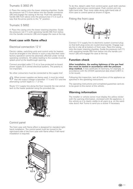
4. Place the casing onto the lower retaining shackles. Guide<br />
the pressure rod (11) from below into the handle connector<br />
(26) and engage the casing at the top. Push the operating<br />
handle (55) from above onto the pressure bar (11) in such a<br />
way that the arrow points to the “0“ position.<br />
<strong>Trumatic</strong> S <strong>5002</strong><br />
4. Place the casing onto the lower retaining shackles. Guide<br />
the pressure rod (11) with operating handle (55) from below<br />
into the handle connector (26) and engage the case at the top.<br />
Front case with flame effect<br />
Electrical connection 12 V<br />
Electric cables, switching units and control units for heaters<br />
must be arranged in the vehicle in such a way that their satisfactory<br />
operation cannot be adversely affected under normal<br />
operating conditions. All cables leading to the outside must be<br />
splash proof at the leadthrough opening.<br />
Connect provided cable (1.5 m) to fuse-protected on-board<br />
power supply (5 A central electrical system). The polarity is<br />
not important.<br />
No other consumers must be connected to the supply line!<br />
When power supplies are being used, it must be noted<br />
that the output voltage is between 11 V and 15 V and the<br />
alternating current ripple is < 1.2 Vss.<br />
Route 12 V supply line along the floor towards the rear and attach<br />
to the heater pedestal using the provided clip.<br />
Control panel<br />
+ 12 V<br />
The front case with flame effect is designed for standard righthand<br />
installation. The control panel must be moved to the<br />
right-hand side of the front case with flame effect if left-hand<br />
installation is required.<br />
12 V<br />
To do this, detach cable from control panel, push both catches<br />
together and remove control panel. Push control unit into<br />
right-hand side. Then route cable along right-hand side of<br />
front case to control panel as shown in figure.<br />
Fitting the front case<br />
d 12 V<br />
Connect 12 V supply line to electronic system (connect plug<br />
so that both plug wires are routed downwards). Engage supply<br />
line in clip (d) at bottom of front case. Place the casing<br />
onto the lower retaining shackles. Guide the pressure rod (11)<br />
with operating handle (55) from below into the handle connector<br />
(26) and engage the case at the top.<br />
Function check<br />
After installation, the sealing tightness of the gas feed<br />
line must be tested in accordance with the pressure<br />
drop method. A test certificate (in Germany, for example, in<br />
accordance with the DVGW operational data sheet G 607) is<br />
to be issued.<br />
Following this inspection, test all functions of the appliance as<br />
specified in the operating instructions.<br />
The operating instructions and completed guarantee card are<br />
to be given to the owner of the vehicle.<br />
Warning information<br />
The installer or vehicle owner must display the yellow sticker<br />
with the warning information, enclosed with the appliance, in<br />
the vehicle so it is clearly visible to all users (e.g. on the wardrobe<br />
door)! Ask Truma to send you a sticker if necessary.<br />
11