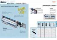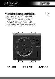
attuatore dimmer per ballast elettronici (1-10v) - 3 canali ... - Gewiss
attuatore dimmer per ballast elettronici (1-10v) - 3 canali ... - Gewiss
attuatore dimmer per ballast elettronici (1-10v) - 3 canali ... - Gewiss

Create successful ePaper yourself
Turn your PDF publications into a flip-book with our unique Google optimized e-Paper software.
I<br />
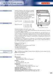
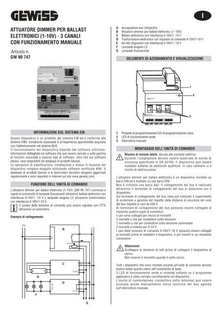
ATTUATORE DIMMER PER BALLAST<br />
ELETTRONICI (1-10V) - 3 CANALI<br />
CON FUNZIONAMENTO MANUALE<br />
Articolo n.<br />
GW 90 747<br />
A<br />
B<br />
C<br />
D<br />
E<br />
F<br />
G<br />
Accoppiatore bus (integrato)<br />
Attuatore <strong>dimmer</strong> <strong>per</strong> <strong>ballast</strong> <strong>elettronici</strong> (1 -10V)<br />
Ballast elettronico con interfaccia 0-10V/1 -10 V<br />
Trasformatore elettronico con ingresso di comando 0-10V/1-10 V<br />
Ad altri dispositivi con interfaccia 0-10V/1 -10 V<br />
Lampade alogene LV<br />
Lampada fluorescente<br />
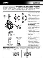
OELEMENTI DI AZIONAMENTO E VISUALIZZAZIONE<br />
1<br />
RUN<br />
2<br />
®<br />
instabus EIB<br />
EIB KNX<br />
3<br />
INFORMAZIONI SUL SISTEMA EIB<br />
Questo dispositivo è un prodotto del sistema EIB ed è conforme alle<br />
direttive KNX. Condizione essenziale è un’es<strong>per</strong>ienza approfondita acquisita<br />
con l’addestramento nel sistema BUS.<br />
Il funzionamento del dispositivo dipende dal software utilizzato.<br />
Informazioni dettagliate sul software che può essere caricato e sulla gamma<br />
di funzioni associate a ciascun tipo di software, oltre che sul software<br />
stesso, sono disponibili nel database di prodotti <strong>Gewiss</strong>.<br />
Le o<strong>per</strong>azioni di pianificazione, installazione e messa in funzione del<br />
dispositivo vengono eseguite utilizzando software certificato KNX. Il<br />
database di prodotti <strong>Gewiss</strong> e le descrizioni tecniche vengono aggiornati<br />
regolarmente e sono re<strong>per</strong>ibili in Internet sul sito www.gewiss.com.<br />
FUNZIONE DELL’UNITÀ DI COMANDO<br />
L’<strong>attuatore</strong> <strong>dimmer</strong> <strong>per</strong> <strong>ballast</strong> <strong>elettronici</strong> (1-10V) (GW 90 747) commuta e<br />
regola la luminosità di lampade fluorescenti attraverso <strong>ballast</strong> <strong>elettronici</strong> con<br />
interfaccia 0-10V/1 -10 V e lampade alogene LV attraverso trasformatori<br />
con interfaccia 0-10V/1-10 V.<br />
Il campo della tensione di comando può essere regolato con l’ETS<br />
attraverso un parametro.<br />
Esempio di collegamento<br />
Bus<br />
+ -<br />
A<br />
B<br />
L<br />
L1 N<br />
1 Pulsante di programmazione/LED di programmazione rosso<br />
2 LED di funzionamento verde<br />
3 Interruttore manuale<br />
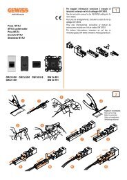
MONTAGGIO DELL’UNITÀ DI COMANDO<br />
Rischio di lesione fatale dovuta alla corrente elettrica.<br />
Durante l’installazione devono essere osservate le norme di<br />
sicurezza specificate in EN 50105. Il dispositivo può essere<br />
installato soltanto da elettricisti qualificati. In caso contrario vi è<br />
rischio di elettrocuzione.<br />
L’<strong>attuatore</strong> <strong>dimmer</strong> <strong>per</strong> <strong>ballast</strong> <strong>elettronici</strong> è un dispositivo montato su<br />
barra DIN ed è montato su una barra DIN.<br />
Non è richiesta una barra dati. Il collegamento del bus è realizzato<br />
attraverso il terminale di collegamento del bus in dotazione con il<br />
dispositivo.<br />
Sul terminale di collegamento del bus viene poi collocato il co<strong>per</strong>chietto<br />
di protezione a garanzia del rispetto della distanza di sicurezza del cavo<br />
del bus rispetto ai cavi da 230 V.<br />
Al terminale di collegamento del bus possono essere collegate al<br />
massimo quattro copie di conduttori.<br />
I cavi sono collegati <strong>per</strong> mezzo di morsetti:<br />
2 morsetti a vite <strong>per</strong> conduttori sotto tensione<br />
1 morsetto a vite <strong>per</strong> conduttore sotto tensione commutato<br />
2 morsetti a innesto <strong>per</strong> 0-10 V<br />
I cavi della tensione di comando 0-10V/1-10 V possono essere collegati<br />
ai morsetti prima di installare il dispositivo, e poi inseriti in un momento<br />
successivo.<br />
0-10V<br />
-<br />
+<br />
Attenzione!<br />
Scollegare la tensione di rete prima di collegare il dispositivo al<br />
carico.<br />
Non inserire il morsetto quando è sotto carico.<br />
F<br />
G<br />
12V AC<br />
C<br />
D<br />
0-10V<br />
0-10V<br />
L<br />
N<br />
-<br />
+<br />
L<br />
N<br />
-<br />
+<br />
Tutti i dispositivi che sono montati accanto all’unità di comando devono<br />
essere dotati quanto meno dell’isolamento di base.<br />
Il LED di funzionamento verde si accende soltanto se il programma<br />
applicativo è stato caricato correttamente nel dispositivo.<br />
L’uscita di commutazione (conduttore sotto tensione) può essere<br />
azionata anche manualmente senza tensione del bus agendo<br />
sull’interruttore manuale.<br />
E
MESSA IN FUNZIONE DELL’UNITÀ DI COMANDO<br />
Rischio di lesione fatale:<br />
Gli interventi sull’unità possono essere eseguiti soltanto da elettricisti<br />
qualificati. Rispettare i regolamenti vigenti nel paese di utilizzo del<br />
dispositivo, unitamente alle direttive EIB vigenti.<br />
1 Caricare l’indirizzo fisico nell’ingresso binario da ETS via EIB.<br />
2 Eseguire le impostazioni di configurazione in ETS e trasferirle.<br />
DATI TECNICI<br />
Alimentazione dal bus: DC 24 V / circa 17,5 mA<br />
Tensioni di isolamento: AC 4 kV bus/tensione di rete e bus / 0-10<br />
V<br />
AC 4 kV 0-10<br />
V - tensione di rete<br />
Contatto di commutazione: contatto di chiusura, flottante<br />
Dati di connessione <strong>per</strong> ogni canale:<br />
Corrente nominale: 16 A; carico induttivo a cos ϕ = 0,6<br />
Lampade a incandescenza: 3600 watt<br />
Lampade alogene: 230 V AC 2500 watt<br />
Lampade alogene (LV): max. 2000 W tramite trasformatori <strong>elettronici</strong> (<strong>per</strong><br />
es. 14 MET S 105 W)<br />
Lampade fluorescenti: 3600 VA non compensate<br />
Carico capacitivo: 3600, 200 μF<br />
Protezione: Il contatto di commutazione deve essere protetto da un<br />
sezionatore 16 A collegato in serie.<br />
Durata di servizio: > 50.000 cicli di commutazione al carico nominale 0-<br />
10V/1-10V<br />
Interfaccia: 0-10 V <strong>per</strong> <strong>ballast</strong> <strong>elettronici</strong> <strong>dimmer</strong>abili, trasformatori MET S<br />
(possono essere regolati tramite parametri)<br />
Capacità di carico: max. 100 mA (max. 50 <strong>ballast</strong> <strong>elettronici</strong>, a seconda dei<br />
<strong>ballast</strong> <strong>elettronici</strong>)<br />
Tensione di comando min.: 0 V<br />
Tem<strong>per</strong>atura ambiente:<br />
- Esercizio: da -5 °C a +45 °C<br />
- Conservazione: da -25 °C a +55 °C<br />
- Trasporto: da -25 °C a +70°C<br />
- Umidità max.: 93 %<br />
- Ambiente: Il dispositivo è progettato <strong>per</strong> l’uso fino ad un’altitudine<br />
d’installazione di 2000 m s.l.m.<br />
Connettori:<br />
- Bus: tramite due pin da 1 mm <strong>per</strong> morsetto di collegamento al bus<br />
- Conduttore sotto tensione e uscita di commutazione: morsetti a vite a<br />
3 vie <strong>per</strong> max. 2,5 mm 2<br />
- Uscita 1-10 V: morsetti a innesto a 2 poli con collegamento a vite <strong>per</strong><br />
max. 2,5 mm 2<br />
Tipo di protezione: IP 20<br />
Direttive CE: conforme alla Direttiva 73/23/CEE sulla bassa tensione,<br />
conforme alla Direttiva EMC 89/336/CEE<br />
Dimensioni: 90x72x65 mm (HxLxD)<br />
Larghezza del dispositivo: 4 TE = 72 mm<br />
GEWISS - MATERIALE ELETTRICO<br />
SAT<br />
+39 035 946 111<br />
8.30 - 12.30 / 14.00 - 18.00<br />
for monday to friday<br />
+39 035 946 260<br />
24 hours/day<br />
SAT on line<br />
@ gewiss@gewiss.com
GB<br />
DIMMING ACTUATOR FOR ELECTRONIC<br />
BALLASTS (1-10V) - 3 CHANNELS WITH<br />
MANUAL OPERATION<br />
Article no.<br />
GW 90 747<br />
A<br />
B<br />
C<br />
D<br />
E<br />
F<br />
G<br />
Bus coupler (built-in)<br />
Dimming actuator for electronic <strong>ballast</strong>s (1-10V)<br />
Electronic <strong>ballast</strong> with 0-10V/1-10 V interface<br />
Electronic transformer with 0-10V/1-10 V control input<br />
To other devices with 0-10V/1-10 V interface<br />
LV halogen lamps<br />
Fluorescent lamp<br />
OPERATING AND DISPLAY ELEMENTS<br />
1<br />
RUN<br />
2<br />
®<br />
instabus EIB<br />
EIB KNX<br />
3<br />
EIB SYSTEM INFORMATION<br />
This device is an EIB system product and conforms to KNX directives.<br />
Detailed ex<strong>per</strong>tise gained through training in the BUS system is a<br />
prerequisite.<br />
The function of the device depends on the software used.<br />
Detailed information on which software can be loaded and the range of<br />
functions associated with each type of software, and the software itself,<br />
are available from the <strong>Gewiss</strong> product database.<br />
Planning, installation and commissioning of the device are carried out<br />
using KNX-certified software. The product database and the technical<br />
descriptions are updated regularly and can be found on the Internet at<br />
www.gewiss.com.<br />
WHAT YOU CAN DO WITH THE CONTROL UNIT<br />
The dimming actuator for electronic <strong>ballast</strong>s 1-10V (GW 90 747) dims<br />
and switches fluorescent lamps via electronic <strong>ballast</strong>s with a 0-10V/1-10<br />
V interface and LV halogen lamps via transformers with a 0-10V/1-10 V<br />
interface.<br />
The control voltage range can be set with the ETS via a parameter.<br />
Connection example<br />
1 Programming button/Programming LED, red<br />
2 O<strong>per</strong>ating LED, green<br />
3 Manual switch<br />
HOW TO MOUNT THE CONTROL UNIT<br />
Risk of fatal injury from electrical current.<br />
During installation, the safety regulations specified in EN 50105 must<br />
be observed. The device may only be installed by skilled electricians.<br />
Otherwise, there is a risk of fire or electrocution.<br />
The dimming actuator for electronic <strong>ballast</strong>s is a DIN rail mounted device and<br />
is mounted onto a DIN rail. A data rail is not required. The bus connection is<br />
carried out via the bus connecting terminal supplied with the device.<br />
The cable cover is then placed over the bus connecting terminal to guarantee<br />
the safety clearance of the bus cable to the 230 V cables. A maximum of four<br />
core pairs can be connected to the bus connecting terminal.<br />
The cables are connected via terminals:<br />
2 screw terminals for live conductors<br />
1 screw terminal for switched live conductor<br />
2 plug-in terminals for 0-10 V<br />
The cables of the 0-10V/1-10 V control voltage can be connected to the<br />
terminals prior to installing the device and then inserted at a later date.<br />
Bus<br />
+ -<br />
F<br />
G<br />
A<br />
12V AC<br />
B<br />
C<br />
D<br />
0-10V<br />
0-10V<br />
0-10V<br />
L<br />
-<br />
+<br />
L<br />
N<br />
-<br />
+<br />
L<br />
N<br />
-<br />
+<br />
L1 N<br />
Caution!<br />
Disconnect the mains voltage before connecting the device to the load.<br />
Do not insert the terminal when it is under load.<br />
All the devices that are mounted next to the control unit must at least be fitted<br />
with basic insulation.<br />
The green o<strong>per</strong>ating LED only lights up if the application program has been<br />
loaded correctly into the device.<br />
Any switch output (switched live conductor) can also be o<strong>per</strong>ated manually<br />
without bus voltage using the manual switch.<br />
HOW TO PUT THE CONTROL UNIT INTO OPERATION<br />
Risk of fatal injury:<br />
All work carried out on the unit may only be <strong>per</strong>formed by skilled<br />
electricians. Observe the regulations valid in the country of use, as<br />
well as the valid EIB directives.<br />
1 Load the physical address into the device from the ETS via EIB.<br />
2 Make the configuration settings in ETS and transfer them.<br />
E
TECHNICAL DATA<br />
Power supply from the bus: DC 24 V / approx. 17.5 mA<br />
Insulation voltages: AC 4 kV bus/mains voltage and bus / 0-10<br />
V<br />
AC 4 kV 0-10<br />
V - mains voltage<br />
Switch contact Make contact, floating<br />
Connection data for each channel:<br />
Nominal current: 16 A; inductive load at cos ϕ = 0.6<br />
Incandescent lamps: 3600 watt<br />
Halogen lamps: 230 V AC 2500 watt<br />
Halogen lamps (LV): max. 2000 W via electronic transformers (e. g. 14 MET<br />
S 105 W)<br />
Fluorescent lamps: 3600 VA uncompensated<br />
Capacitive load: 3600, 200 μF<br />
Protection The switch contact must be protected by a seriesconnected 16 A<br />
circuit-breaker.<br />
Service life: > 50,000 switching cycles at nominal load 0-10V/1-10V<br />
Interface: 0-10 V for dimming electronic <strong>ballast</strong>s, MET S transformers (can<br />
be set via parameters)<br />
Loading capacity: max. 100 mA (max. 50 electronic <strong>ballast</strong>s; depending on<br />
electronic <strong>ballast</strong>s)<br />
Min. control voltage: 0 V<br />
Ambient tem<strong>per</strong>ature:<br />
- O<strong>per</strong>ation: -5 °C to +45 °C<br />
- Storage: -25 °C to +55 °C<br />
- Transport: -25 °C to +70 °C<br />
- Max. humidity: 93 %<br />
- Environment The device is designed for use at a height up to 2000 m<br />
above sea level.<br />
Connections<br />
- Bus: via two 1 mm pins for bus connecting terminal<br />
- Live conductor and switch output: 3-gang screw terminals for max.<br />
2.5 mm 2<br />
- 1-10 V output: 2-pole plug-in terminals with screw connection for<br />
max. 2.5 mm 2<br />
Type of protection: IP 20<br />
EC directives: complies with low-voltage directive 73/23/EEC, complies<br />
with EMC directive 89/336/EEC<br />
Dimensions: 90x72x65 mm (HxWxD)<br />
Device width: 4 TE = 72 mm<br />
GEWISS - MATERIALE ELETTRICO<br />
SAT<br />
+39 035 946 111<br />
8.30 - 12.30 / 14.00 - 18.00<br />
for monday to friday<br />
+39 035 946 260<br />
24 hours/day<br />
SAT on line<br />
@ gewiss@gewiss.com<br />
ULTIMA REVISIONE 12/2007 cod. 7.01.2.788.1