Retractable Air & Water Hose Reels Parts and Technical Service ...
Retractable Air & Water Hose Reels Parts and Technical Service ...
Retractable Air & Water Hose Reels Parts and Technical Service ...

You also want an ePaper? Increase the reach of your titles
YUMPU automatically turns print PDFs into web optimized ePapers that Google loves.
SEVEN POSITION LOCKING BRACE<br />
LEVELWIND retractable hose reels can swing freely on bracket or<br />
can be locked in one of seven positions, allowing for specific<br />
mounting requirements.<br />
Fig. 5a Fig. 5b Fig. 6<br />
St<strong>and</strong>ard bracket<br />
1) Remove bracket rod from reel. (SEE FIGURE 5A)<br />
2) Place seven position locking brace over bracket so that bracket<br />
rod holes are aligned. Replace bracket rod so that brace, reel &<br />
bracket are attached. Insert hitch-pin clip through end of<br />
bracket rod.(SEE FIGURE 5B)<br />
3) Rotate bracket so that it is at desired angle & lock into place<br />
with fastener. (SEE FIGURE 5B)<br />
Maintenance Procedures<br />
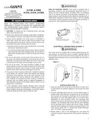
TENSION ADJUSTMENT:<br />
This reel is preloaded with spring tension that is set at the factory. If<br />
the reel becomes completely un-tensioned, please identify your hose<br />
reel model number referenced in the Factory Preset Tensioning Table<br />
to find out how many turns are needed for proper tensioning. If a<br />
heavy air tool is attached to the end of the hose, you may need to<br />
add tension to overcome the weight of this tool. DO NOT EXCEED<br />
one full turn past the number of turns listed in the Factory Preset<br />
Tensioning Chart below.<br />
TOOLS REQUIRED:<br />
Phillips Screw Driver, 3/4 in. Socket Wrench<br />
Fig.7<br />
1) Lay reel on its side. ( SEE FIGURE 7 )<br />
2) Place wrench on hub fitting plate nut. HOLD WRENCH FIRMLY.<br />
3) Unscrew hub. DO NOT REMOVE SIDEPLATE.<br />
4) Turn wrench either ½ turn or no more than one full turn. Turn<br />
clock wise to increase tension. Turn counterclockwise to<br />
decrease tension.<br />
5) Replace hub plate screws <strong>and</strong> tighten. Return reel to mounting bracket.<br />
Optional Bench/High Wall<br />
Mounting Bracket<br />
(see figure 6)<br />
Factory Preset Tensioning Table<br />
Model #<br />
# of Turns<br />
L8305 3<br />
L8305-EU 3<br />
L8306 5<br />
L8306-EU 5<br />
L8310 4<br />
L8310-EU 4<br />
L8335 4<br />
L8335-EU 4<br />
L8344 4<br />
L8345 4<br />
L8346 4<br />
L8347 4<br />
L8349 4<br />
L8350 11<br />
L8350-EU 11<br />
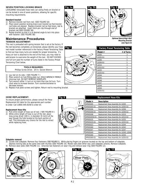
HOSE REPLACEMENT:<br />
To ensure proper performance, please consult the <strong>Hose</strong><br />
Replacement Kit table for the appropriate part number<br />
to order. Call 1(800) 645-8258 to order kit.<br />
Replacement <strong>Hose</strong> Kits<br />
1) Pull entire length of hose out of reel. ( SEE FIGURE 8 )<br />
2) While entire length of hose is out of the reel, place<br />
long screw driver (3/8 in. in diameter (9 mm)) all the<br />
way though the hole located at the back portion of<br />
reel. This eliminates any chance for the reel to retract<br />
while replacing hose.<br />
Fig. 8<br />
Model #<br />
RP005005<br />
RP005005-EU<br />
RP005006<br />
RP005006-EU<br />
RP005008<br />
RP0050058-EU<br />
RP005035<br />
RP005035-EU<br />
RP005023<br />
Replacement <strong>Hose</strong> Kits<br />
Description<br />
Replacement <strong>Hose</strong> Assembly for L8305<br />
Replacement <strong>Hose</strong> Assembly for L8305-EU<br />
Replacement <strong>Hose</strong> Assembly for L8306<br />
Replacement <strong>Hose</strong> Assembly for L8306-EU<br />
Replacement <strong>Hose</strong> Assembly for L8310<br />
Replacement <strong>Hose</strong> Assembly for L8310-EU<br />
Replacement <strong>Hose</strong> Assembly for L8335<br />
Replacement <strong>Hose</strong> Assembly for L8335-EU<br />
Replacement <strong>Hose</strong> Assembly for L8344<br />
RP005069 Replacement <strong>Hose</strong> Assembly for L8345<br />
RP005047 Replacement <strong>Hose</strong> Assembly for L8347<br />
RP005049 Replacement <strong>Hose</strong> Assembly for L8349, L8346<br />
RP005069 Replacement <strong>Hose</strong> Assembly for L8350<br />
RP005069-EU Replacement <strong>Hose</strong> Assembly for L8350-EU<br />
Sideplate removal<br />
3) Locate inlet sideplate. Remove four fasteners (SEE FIGURE 9 ). While placing fingers on grooves located on the top <strong>and</strong> bottom of sideplate,<br />
depress locking tabs at the same time with thumbs (SEE FIGURE 10). Rotate side plate either way until sideplate unlocks. Remove sideplate.<br />
4) Remove wear plate (SEE FIGURE 11). Unscrew two fasteners on wear ring <strong>and</strong> remove wear ring (SEE FIGURE 12).<br />
Fig. 9 Fig. 10 Fig. 11 Fig. 12<br />
P.2