Proiettori di profili Proiettori di profili
Proiettori di profili Proiettori di profili
Proiettori di profili Proiettori di profili

Create successful ePaper yourself
Turn your PDF publications into a flip-book with our unique Google optimized e-Paper software.
<strong>Proiettori</strong> <strong>di</strong> <strong>profili</strong><br />
Il nome che ha segnato la storia dei proIettorI<br />
the brand name which has marked<br />
the history of the profIle projectors
<strong>Proiettori</strong> <strong>di</strong> <strong>profili</strong><br />
Da oltre 70 anni il nome Microtecnica è legato in<strong>di</strong>ssolubilmente ai proiettori<br />
<strong>di</strong> <strong>profili</strong>. Risale infatti al 1940 la prima fornitura <strong>di</strong> un proiettore <strong>di</strong><br />
<strong>profili</strong> all’allora Gran<strong>di</strong> Motori <strong>di</strong> Torino, azienda del gruppo FIAT,<br />
che costruiva, fra l’altro motori marini.<br />
Da quella prima referenza, oltre 10.000 esemplari <strong>di</strong><br />
proiettori <strong>di</strong> <strong>profili</strong> Microtecnica si sono affermati in<br />
oltre 50 paesi, contrad<strong>di</strong>stinguendosi sempre per<br />
l’affidabilità e l’alta precisione<br />
ottico/meccanica derivante dalle sue<br />
lavorazioni ad alto contenuto tecnologico<br />
nei settori aeronautico e spaziale.<br />
The Microtecnica name has been<br />
inseparably bound to profile<br />
projectors for over 70 years. In<br />
fact in 1940 the first Microtecnica<br />
profile projector was supplied to<br />
M/s Gran<strong>di</strong> Motori – company<br />
belonging to the FIAT group,<br />
manufacturing, among others,<br />
marine engines. After that first<br />
reference more than 10.000<br />
Microtecnica profile projectors<br />
have been supplied in over 50<br />
countries, <strong>di</strong>stinguishing for their<br />
reliability and high precision in<br />
both optical and mechanical parts<br />
as a result of Microtecnica high<br />
technology production in aeronautic<br />
and aerospace sectors.
peculiarità<br />
dei proiettori <strong>di</strong> <strong>profili</strong> MICROTECNICA<br />
La progettazione e lavorazione delle lenti e specchi,<br />
che rappresentano il cuore dei proiettori <strong>di</strong> <strong>profili</strong>,<br />
avvengono attraverso calcoli ottici de<strong>di</strong>cati ed<br />
apparecchiature molto sofisticate in grado <strong>di</strong> garantire<br />
il massimo livello qualitativo. Si riesce così ad ottenere<br />
lenti e specchi ad alta definizione, luminosità e<br />
precisione la cui qualità è sintetizzata dai seguenti<br />
fattori:<br />
<strong>di</strong>storsione ottica fino allo 0,02% su tutta la superficie<br />
dello schermo <strong>di</strong> proiezione<br />
incertezza <strong>di</strong> misura sull’intero campo <strong>di</strong> misura del<br />
gruppo tavole fino a: +/- (2,5 + L/100 )= µm<br />
La Microtecnica vanta, tra i suoi primati, quello <strong>di</strong> essere<br />
stata la PRIMA azienda al mondo a realizzare, nel lontano<br />
1954, un proiettore <strong>di</strong> <strong>profili</strong> con schermo <strong>di</strong> proiezione<br />
da 1.000 mm; proprio recentemente la LTF ha lanciato<br />
sul mercato internazionale il nuovo modello Microtecnica<br />
Maximus1.5 con schermo <strong>di</strong>ametro 1.500 mm.<br />
Un secondo primato Microtecnica riguarda la<br />
posizione angolata del gruppo tavole, rispetto allo<br />
schermo, con conseguente ergonomia dell’impiego del<br />
proiettore <strong>di</strong> <strong>profili</strong> <strong>di</strong> gran<strong>di</strong> <strong>di</strong>mensioni.<br />
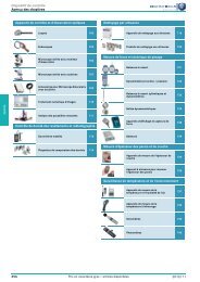
▲ Banco ottico universale con<br />
<strong>di</strong>spositivo laser per controllo delle<br />
caratteristiche dei sistemi ottici.<br />
Optical Bench with laser for optical<br />
systems checking.<br />
▲ Macchina sotto vuoto per la metallizzazione degli specchi<br />
con deposito <strong>di</strong> uno strato <strong>di</strong> pochi millesimi <strong>di</strong> alluminio<br />
polverizzato per ottenere la loro superficie riflettente.<br />
Vacuum equipment for mirror metallisation (aluminizing)<br />
consisting of few micron layer of nebulised aluminium to<br />
obtain the surface reflection of the optical mirrors.<br />
4
<strong>Proiettori</strong> <strong>di</strong> <strong>profili</strong><br />
The design and the manufacturing process of both<br />
lenses and mirrors, which are the heart of the profile<br />
projectors, are made through de<strong>di</strong>cated optical<br />
calculations and very sophisticated equipment granting<br />
the state of the art for these kinds of instruments. The<br />
result is manufacturing lenses and mirrors of highest<br />
resolution, brightness and provi<strong>di</strong>ng the following<br />
accuracies:<br />
Optical <strong>di</strong>stortion up to 0,02% over the whole screen<br />
Measuring uncertainty on the whole field of the<br />
worktable <strong>di</strong>splacements up to: +/- (2,5+L/100 )= µm<br />
Due to their supremacy, Microtecnica in 1954 became<br />
the FIRST manufacturer in the world to produce a<br />
manufacturing<br />
peculiarities<br />
of microtecnica<br />
profile projectors<br />
profile projector with a 1.000 mm <strong>di</strong>ameter screen;<br />
just recently LTF have launched the new Microtecnica<br />
Model Maximus 1.5 with 1.500 mm screen <strong>di</strong>ameter<br />
on the international market. A second benchmark<br />
of Microtecnica leadership concerns the worktable<br />
positioned at the side in an angular and convenient<br />
position to the projection screen. This ergonomic<br />
design, another Microtecnica primacy, makes the<br />
checking operations extremely convenient, reduces the<br />
operator strain and the possibility of human error on<br />
large size models.<br />
▲ Prima pagina del libro matricola dalla quale appare<br />
l’assegnazione della matricola N.1 al proiettore <strong>di</strong> <strong>profili</strong><br />
modello M23-GR-530-03 fornito alla Fiat Gran<strong>di</strong> Motori<br />
<strong>di</strong> Torino nel 1940.<br />
The first page of original Microtecnica serial number register<br />
reporting N. 1 assigned to profile projector<br />
model M23-GR-530-03 delivered to M/s FIAT Gran<strong>di</strong> Motori,<br />
Torino in 1940.<br />
1939.<br />
Modello 530-01<br />
da Banco con<br />
schermo<br />
<strong>di</strong>ametro 250 mm.<br />
1939.<br />
Bench<br />
Model 530-01 with<br />
250 mm screen<br />
<strong>di</strong>ameter.<br />
▲<br />
5
ASSISTENZA<br />
tecnica<br />
e promozione<br />
ven<strong>di</strong>te<br />
L’Esperienza<br />
è garanzia <strong>di</strong> competenza<br />
La LTF assicura, con il suo staff<br />
<strong>di</strong> tecnici altamente specializzati,<br />
l’assistenza tecnica, consulenza<br />
applicativa e la certificazione <strong>di</strong><br />
tutto il parco proiettori <strong>di</strong> <strong>profili</strong><br />
Microtecnica sparsi in tutto il mondo.<br />
L’unità mobile è <strong>di</strong>sponibile per<br />
la <strong>di</strong>mostrazione pratica, presso<br />
potenziali Clienti, della maggior parte<br />
<strong>di</strong> strumenti da banco<br />
LTF/Borletti, nonché dei<br />
<strong>Proiettori</strong> <strong>di</strong> Profili Microtecnica e<br />
Durometri/Microdurometri Galileo.<br />
SERVICE<br />
and sale<br />
promotion<br />
LTF and their team of skilled<br />
engineers assure full service<br />
and technical support as well as<br />
the certified statement of the<br />
existing Microtecnica profile<br />
projectors widespread all over the<br />
world. A demo mobile truck is at<br />
Customers’ <strong>di</strong>sposal for door to door<br />
demonstrations of most<br />
LTF/Borletti hand measuring tools<br />
as well as Microtecnica Profile<br />
Projectors and Galileo<br />
Hardness/Microhardness testers.<br />
L’assioma ben si ad<strong>di</strong>ce al nome Microtecnica che<br />
ha segnato la storia dei proiettori <strong>di</strong> <strong>profili</strong>. La LTF si<br />
assume l’onore e l’impegno <strong>di</strong> garantire la continuità<br />
<strong>di</strong> tale esperienza avvalendosi della propria struttura<br />
produttiva certificata ISO 9001:2008.<br />
This axiom matches the Microtecnica name which<br />
has marked the history of profile projectors. LTF is<br />
constantly applying this important experience by means<br />
of their production facilities duly certified<br />
ISO 9001:2008.<br />
6
<strong>Proiettori</strong> <strong>di</strong> <strong>profili</strong><br />
Experience<br />
is a guarantee<br />
of competence<br />
Presso gli Stabilimenti LTF in Antegnate (Bergamo), che<br />
occupano una superficie <strong>di</strong> 55.000 mq avvengono le<br />
lavorazioni, montaggi, messa a punto e collau<strong>di</strong> <strong>di</strong> tutti i<br />
modelli Microtecnica che la LTF vende in oltre 50 Paesi.<br />
Oltre al settore dei proiettori <strong>di</strong> <strong>profili</strong>, negli stessi<br />
Stabilimenti, la LTF produce la gamma completa<br />
<strong>di</strong> Durometri e Microdurometri Galileo, nonché gli<br />
strumenti <strong>di</strong> misura Borletti.<br />
The Main LTF Plants are located at Antegnate<br />
(Bergamo) on a site of 55.000 sqm provi<strong>di</strong>ng the<br />
manufacturing, setting up and testing of the full range<br />
of Microtecnica profile projectors sold by LTF in more<br />
than 50 Countries.<br />
Besides profile projectors, the same Plant produce<br />
the line of Galileo Hardness/Microhardness Testers as<br />
well the Borletti Precision Instruments for Measuring<br />
and Testing.<br />
7
Centro <strong>di</strong> Taratura<br />
ACCREDIA<br />
LAT N. 067<br />
Centro <strong>di</strong> Taratura Accre<strong>di</strong>a<br />
LAT N. 067, presso la LTF, per la<br />
taratura della maggior parte <strong>di</strong><br />
strumenti <strong>di</strong> misura e controllo;<br />
il centro comprende la macchina<br />
primaria Galileo per la taratura,<br />
fra l’altro, dei provini <strong>di</strong> durezza e<br />
penetratori per prove Rockwell,<br />
Brinell e Vickers.<br />
Accre<strong>di</strong>a Calibration Centre<br />
N. LAT 067 located at LTF to<br />
calibrate most of the measuring<br />
and Testing instruments; the<br />
centre inclu<strong>di</strong>ng Primary Galileo<br />
Hardness Tester to carry out,<br />
among others the calibration<br />
of test blocks and indenters for<br />
Rockwell, Brinell and Vickers tests.<br />
8
<strong>Proiettori</strong> <strong>di</strong> <strong>profili</strong><br />
La tabella <strong>di</strong><br />
accre<strong>di</strong>tamento completa<br />
è scaricabile dal sito<br />
Accre<strong>di</strong>a: www.accre<strong>di</strong>a.it<br />
▲<br />
The complete<br />
accre<strong>di</strong>tation table can<br />
be downloaded from the<br />
Accre<strong>di</strong>a website:<br />
www.accre<strong>di</strong>a.it<br />
Calibration Centre<br />
ACCREDIA<br />
LAT N. 067<br />
La LTF, a conferma dell’esperienza acquisita, è titolare<br />
del Centro <strong>di</strong> Taratura Accre<strong>di</strong>a LAT N. 067 per le<br />
grandezze, lunghezze e durezze, come riportato nella<br />
tabella <strong>di</strong> accre<strong>di</strong>tamento pubblicato sul sito<br />
www.accre<strong>di</strong>a.it.<br />
Attualmente il Centro <strong>di</strong> Taratura Accre<strong>di</strong>a LAT N. 067<br />
è il solo ad essere accre<strong>di</strong>tato per la certificazione dei<br />
proiettori <strong>di</strong> <strong>profili</strong>, tale accre<strong>di</strong>tamento risale al 1995.<br />
To confirm the experience acquired, LTF own the<br />
Calibration Centre Accre<strong>di</strong>a LAT N. 067 for sizes, lengths<br />
and hardness as reproduced in the accre<strong>di</strong>tation table<br />
published in the website www.accre<strong>di</strong>a.it.<br />
At present the Accre<strong>di</strong>a Calibration Centre LAT N. 067<br />
is the sole accre<strong>di</strong>ted Centre to calibrate profile<br />
projectors. As a matter of fact in 1995 LTF received the<br />
involved extension of own Calibration Centre LAT N. 067.<br />
9
I modelli Helios ed Orion sono <strong>di</strong>sponibili in due<br />
versioni in relazione alla <strong>di</strong>rezione del sistema <strong>di</strong><br />
proiezione orizzontale o verticale. La versione<br />
orizzontale è particolarmente adatta per il controllo<br />
<strong>di</strong> pezzi cilindrici, da sistemare fra le contropunte,<br />
oppure su supporti a “V”, nonché per particolari da<br />
fissare in morsa. La versione verticale è maggiormente<br />
adatta per il controllo <strong>di</strong> piccoli e sottili componenti da<br />
appoggiare <strong>di</strong>rettamente sul piano in vetro della tavola;<br />
utile soprattutto nel settore della minuteria meccanica,<br />
della plastica, della gomma, dell’elettronica ed affini.<br />
Il modello Ares è caratterizzato dallo spostamento del<br />
corpo proiettore per ottenere la messa a fuoco del pezzo<br />
da verificare. Questa originale soluzione costruttiva,<br />
offre il vantaggio <strong>di</strong> una maggiore precisione degli<br />
spostamenti X– Y della tavola in quanto non subiscono<br />
alcuna variazione durante la messa a fuoco del pezzo.<br />
La composizione standard dei modelli Helios, Orion ed<br />
Ares comprende i trasduttori lineari ed encoder rotante,<br />
nonché il nuovo visualizzatore <strong>di</strong> quote/elaboratore<br />
dati con touch screen modello 780- M-Touch. Il nuovo<br />
sistema permette quin<strong>di</strong> <strong>di</strong> effettuare misure <strong>di</strong>rette nelle<br />
due coor<strong>di</strong>nate ed angolare, come pure l’elaborazione<br />
proiettori<br />
<strong>di</strong> <strong>profili</strong> da banco<br />
Visualizzatore <strong>di</strong><br />
quote/elaboratore dati<br />
modello 780-M-Touch<br />
▲<br />
Digital <strong>di</strong>splays/data<br />
Model 780-M-Touch<br />
delle principali funzioni geometriche. Il <strong>di</strong>spositivo<br />
è completo <strong>di</strong> fibra ottica (sensore ottico) per la<br />
collimazione automatica sullo schermo (esclusivamente<br />
con la proiezione <strong>di</strong>ascopica). Maggiori dettagli a<br />
pag. 32-33.<br />
10<br />
▲ HELIOS<br />
350-H<br />
▲ HELIOS<br />
350-V
<strong>Proiettori</strong> <strong>di</strong> <strong>profili</strong><br />
MODELLI / MODELS<br />
HELIOS<br />
ORION<br />
ARES<br />
Helios and Orion models are available in two versions<br />
accor<strong>di</strong>ng to the <strong>di</strong>rection of the projection system viz.<br />
either horizontal or vertical. The horizontal version is<br />
particularly suitable for checking cylindrical components<br />
to be fixed between dead centres or placed on “V”<br />
supports, as well as for specimens to be clamped by<br />
means of vices. The vertical version is more convenient<br />
for checking small and thin components to be placed<br />
<strong>di</strong>rectly on the glass stage of the worktable. Therefore<br />
this latter version is mainly useful in the production of<br />
small metal ware, as well as plastic, rubber, electronic<br />
components and the alike. A <strong>di</strong>stinguished feature of<br />
the Ares model is the projector body shifting up and<br />
down so as to reach the correct focusing position on<br />
the work-piece. This innovative manufacturing principle<br />
offers the advantage of higher accuracy in the X-Y<br />
worktable <strong>di</strong>splacements since these are not affected<br />
Bench top profile<br />
projectors<br />
by the vertical table movement, which conventionally<br />
occurs during the piece focusing on other projector<br />
models. Standard composition of all Helios, Orion and<br />
Ares models includes the linear transducers and encoder<br />
as well as the new <strong>di</strong>gital <strong>di</strong>splays/data processor with<br />
touch screen model 780-M-Touch. The new system<br />
allows carrying out <strong>di</strong>rect two co-or<strong>di</strong>nates and angular<br />
measurements in ad<strong>di</strong>tion to main geometric functions<br />
data processor. The device is complete with the optical<br />
sensor (edge finder) for on fly measurements with<br />
<strong>di</strong>ascopic projection. See more details on page 32-33.<br />
▲ ORION<br />
400-H<br />
▲ ORION<br />
400-V<br />
▲ ARES<br />
400<br />
11
modello<br />
model<br />
HELIOS<br />
350-H<br />
HELIOS<br />
350-V<br />
ORION<br />
400-H<br />
ORION<br />
400-V<br />
ARES<br />
400<br />
Sistema proiezione<br />
Art. item 780-LM11 780-LM12 780-LM13 780-LM14 780-LM19<br />
Schermo goniometrico con reticolo,<br />
per misurazioni angolari<br />
con visualizzatore, risoluzione 1’<br />
Corpo metallico con visiera paraluce<br />
scorrevole<br />
Braccio porta lampada ribaltabile<br />
Proiezione <strong>di</strong>ascopica con lampada<br />
Projection system<br />
Protractor screen with reticule for<br />
angular measurements with <strong>di</strong>gital<br />
<strong>di</strong>splay, 1’ resolution<br />
All metal projector body with sli<strong>di</strong>ng<br />
darkening hood<br />
Swivelling lamp-holder arm<br />
Diascopic projection with halogen lamp<br />
alogena 150W 24V e ventilazione forzata 150 W 24 V and motor fan lamp cooling<br />
Proiezione episcopica con fibre ottiche Episcopic projection with two way fibre<br />
a due vie e ventilazione forzata optics and motor fan lamp cooling<br />
Protezione automatica<br />
Automatic protection against<br />
contro il surriscaldamento<br />
over-heating<br />
Stand-by automatico per lampade Automatic stand-by for lamps and<br />
e visualizzatore M-Touch<br />
<strong>di</strong>gital <strong>di</strong>splay Model M-Touch<br />
Tavola porta pezzi standard:<br />
Standard worktable:<br />
Dimensioni<br />
Dimensions<br />
Spostamento orizzontale<br />
Horizontal movement<br />
Spostamento trasversale<br />
Transverse movement<br />
Spostamento verticale<br />
Vertical movement<br />
Spostamento <strong>di</strong> messa a fuoco Focussing movement<br />
Rotazione, lettura 1’<br />
Helix, 1’ rea<strong>di</strong>ng<br />
Sistema <strong>di</strong> sganciamento<br />
Release system<br />
per spostamento rapido orizzontale for fast horizontal travel<br />
Peso ammesso (circa)*<br />
Allowed weight (approx)#<br />
asse<br />
axis orizzontale<br />
horizontal<br />
Ø<br />
mm<br />
mm<br />
mm<br />
mm<br />
mm<br />
mm<br />
kg<br />
verticale<br />
vertical<br />
orizzontale<br />
horizontal<br />
verticale<br />
vertical<br />
verticale<br />
vertical<br />
350 350 400 400 400<br />
450x150<br />
200<br />
150<br />
100<br />
+/-15°<br />
15<br />
320x150<br />
200<br />
100<br />
100<br />
10<br />
450x150<br />
250<br />
150<br />
100<br />
+/-15°<br />
15<br />
320x150<br />
200<br />
100<br />
100<br />
10<br />
480x380<br />
305<br />
204<br />
*Nota. Sono ammessi pesi superiori in relazione alla loro posizione sulla tavola / #Note. Heavier weights are permitted subject to the position of the work-piece under testing<br />
Sistema <strong>di</strong> misura spostamenti tavola Measuring system for the worktable<br />
porta pezzi e schermo goniometrico <strong>di</strong>splacements and protractor screen<br />
completo <strong>di</strong>:<br />
consisting of:<br />
Trasduttori lineari ed encoder rotante Linear transducers and rotating encoder<br />
Visualizzatore/Elaboratore dati Digital <strong>di</strong>splays/data processor<br />
modello M-Touch con fibra ottica model M-Touch with optical sensor as<br />
come da descrizione pag. 32-33. per description (pages 32-33).<br />
(A richiesta si possono montare altri (Further kinds of <strong>di</strong>gital <strong>di</strong>splays/data<br />
tipi <strong>di</strong> visualizzatori)<br />
processor available on request)<br />
Controllo numerico per spostamenti<br />
automatici lineari tavola, completo <strong>di</strong>:<br />
Asservimento motori<br />
PC<br />
Software <strong>di</strong> gestione assi<br />
Obiettivo intercambiabile 10X<br />
Obiettivi intercambiabili<br />
20 - 50 - 100 X<br />
Condensatore ottico unificato<br />
Per ottimizzare la prestazione<br />
degli obiettivi 20-50 e 100 X<br />
sono <strong>di</strong>sponibili i rispettivi<br />
condensatori de<strong>di</strong>cati<br />
Alimentazione monofase<br />
220V 50Hz<br />
Dimensioni ingombro (circa):<br />
Larghezza<br />
Profon<strong>di</strong>tà<br />
Altezza<br />
CNC for automatic linear table<br />
<strong>di</strong>splacements complete with:<br />
Drive motors<br />
PC<br />
Software for axes processing<br />
Interchangeable magnification lens 10X<br />
Interchangeable magnifications lenses<br />
20 - 50 - 100 X<br />
Unified optical condenser<br />
To improve the optical performance<br />
of 20-50 and 100X magnification<br />
lenses the de<strong>di</strong>cated respective<br />
optical condensers are available<br />
Power supply voltage 220 V single<br />
phase 50 Hz<br />
Overall <strong>di</strong>mensions (approx):<br />
Width<br />
Depth<br />
Height<br />
Peso netto (circa) Net weight (approx) kg 125 120 130 125 140<br />
Colori standard:<br />
Corpo proiettore<br />
Fasce laterali e colonne luci<br />
Basamento<br />
Standard colours:<br />
Projector body<br />
Lateral bands and lamp holder arm<br />
Base<br />
Legenda: Standard/Standard Opzionale/Optional Non applicabile/Not applicable<br />
mm<br />
mm<br />
mm<br />
460<br />
1150<br />
960<br />
460<br />
750<br />
1100<br />
460<br />
1150<br />
960<br />
460<br />
750<br />
1100<br />
grigio / grey RAL 7038<br />
rosso / red RAL 3000<br />
grigio / grey RAL 7012<br />
100<br />
10<br />
530<br />
820<br />
960<br />
12
<strong>Proiettori</strong> <strong>di</strong> <strong>profili</strong><br />
OBIETTIVI<br />
MAGNIFICATION<br />
LENSES<br />
Distanze frontali degli obiettivi e <strong>di</strong>ametri massimi<br />
dei pezzi controllabili in <strong>di</strong>ascopia orizzontale<br />
Projection field, focal clearance of the magnification lenses,<br />
max. <strong>di</strong>ameter of the workpieces that can be checked<br />
in horizontal <strong>di</strong>ascopic projection<br />
HELIOS 350-H / ORION 400-H<br />
Disegno/Graphic 020 070 102<br />
Obiettivi<br />
Magnification lenses 10X 20X 50X 100X<br />
A mm 87 81 53 43<br />
B mm 140 140 140 111<br />
C mm 185 185 185 140<br />
D mm 204 203 130 89<br />
E mm 290 284 168 113<br />
Legenda:<br />
A – Distanza obiettivo - piano focale<br />
B –Distanza condensatore - piano focale<br />
C –Ø massimo controllabile, metà apertura, asse del pezzo al <strong>di</strong> sotto dell’asse ottico<br />
D –Ø massimo controllabile, totale apertura, asse del pezzo al <strong>di</strong> sotto dell’asse ottico<br />
E –Ø massimo controllabile, metà apertura, asse del pezzo al <strong>di</strong> sopra dell’asse ottico<br />
Legend:<br />
A – Lens focal clearance<br />
B – Condenser clearance<br />
C – Max. work <strong>di</strong>ameter, half aperture, inspected piece center-line below optical axis<br />
D – Max. work <strong>di</strong>ameter, full aperture, inspected piece center-line below optical axis<br />
E – Max. work <strong>di</strong>ameter, half aperture, inspected piece center-line above optical axis<br />
10x<br />
20x<br />
Ø utile / Min. Ø<br />
50x<br />
100x<br />
Ø - E -<br />
- A - - B -<br />
ASSE PIANO FOCALE<br />
AXIS FOCAL PLANE<br />
Ø - D -<br />
Ø - C -<br />
HELIOS 350-V / ORION 400-V<br />
Disegno/Graphic 025 070 006<br />
Obiettivi<br />
20X<br />
Magnification lenses<br />
10X<br />
HELIOS ORION<br />
50X 100X<br />
A mm 87 81 53 43<br />
B mm 69 69 60 69 69<br />
C mm 137 137 120 137 108<br />
D mm 137 137 120 120 89<br />
E mm 137 137 120 137 108<br />
Legenda:<br />
A – Distanza obiettivo – piano tavola<br />
B – Distanza piano tavola – piano focale<br />
C – Ø massimo controllabile, metà apertura, asse del pezzo a sinistra dell’asse ottico<br />
D – Ø massimo controllabile, totale apertura, asse del pezzo a sinistra dell’asse ottico<br />
E – Ø massimo controllabile, metà apertura, asse del pezzo a destra dell’asse ottico<br />
Legend:<br />
A – Lens focal clearance<br />
B – Condenser clearance<br />
C – Max. work <strong>di</strong>ameter, half aperture, inspected piece center-line at the left hand side of the optical axis<br />
D – Max. work <strong>di</strong>ameter, full aperture, inspected piece center-line at the left hand side of the optical axis<br />
E – Max. work <strong>di</strong>ameter, half aperture, inspected piece center-line at the right hand side of the optical axis<br />
Ø utile / Min. Ø<br />
Ø - C -<br />
Ø - D -<br />
10x<br />
20x<br />
50x<br />
100x<br />
Ø - E -<br />
- B - - A -<br />
ASSE PIANO FOCALE<br />
AXIS FOCAL PLANE<br />
ARES<br />
Disegno/Graphic M 040 070 001<br />
Obiettivi<br />
Magnification lenses<br />
10X 20X 50X 100X<br />
A mm 87 81 53 43<br />
B mm 99 90 99 99<br />
C mm 197,5 180 168 108<br />
D mm 197,5 180 120 88<br />
E mm 197,5 180 168 108<br />
Legenda:<br />
A – Distanza obiettivo – piano tavola<br />
B – Distanza piano tavola – piano focale<br />
C – Ø massimo controllabile, metà apertura, asse del pezzo a sinistra dell’asse ottico<br />
D – Ø massimo controllabile, totale apertura, asse del pezzo a sinistra dell’asse ottico<br />
E – Ø massimo controllabile, metà apertura, asse del pezzo a destra dell’asse ottico<br />
Legend:<br />
A – Lens focal clearance<br />
B – Condenser clearance<br />
C – Max. work <strong>di</strong>ameter, half aperture, inspected piece center-line at the left hand side of the optical axis<br />
D – Max. work <strong>di</strong>ameter, full aperture, inspected piece center-line at the left hand side of the optical axis<br />
E – Max. work <strong>di</strong>ameter , half aperture, inspected piece center-line at the right hand side of the optical axis<br />
Nota. I dati possono leggermente variare in relazione al percorso ottico dei singoli modelli <strong>di</strong> proiettori <strong>di</strong> <strong>profili</strong>.<br />
Note. Data are subject to variation accor<strong>di</strong>ng to the optical path of the <strong>di</strong>fferent models of profile projectors.<br />
Ø utile / Min. Ø<br />
ASSE PIANO FOCALE<br />
AXIS FOCAL PLANE<br />
Ø - C -<br />
Ø - D -<br />
10x<br />
20x<br />
50x<br />
100x<br />
Ø - E -<br />
- A -<br />
- B -<br />
13
proiettori<br />
<strong>di</strong> <strong>profili</strong> me<strong>di</strong>a/alta gamma<br />
I modelli Anteus e Sirius sono contrad<strong>di</strong>stinti dal<br />
gruppo tavole in posizione frontale, rispetto allo<br />
schermo <strong>di</strong> proiezione. Al contrario, sull’Atlas, il<br />
gruppo tavola è posizionato lateralmente, rispetto allo<br />
schermo, al fine <strong>di</strong> permettere il libero accostamento<br />
allo stesso da parte dell’operatore. Tale soluzione<br />
ergonomica è soprattutto vantaggiosa in caso <strong>di</strong><br />
utilizzo del proiettore con il tra<strong>di</strong>zionale metodo <strong>di</strong><br />
confronto con i <strong>di</strong>segni teorici. I tre modelli hanno in<br />
comune il gruppo tavole standard <strong>di</strong> 650x150 mm con<br />
spostamenti motorizzati <strong>di</strong> 300x200 mm.<br />
In considerazione delle loro caratteristiche costruttive <strong>di</strong><br />
robustezza, precisione ed affidabilità i modelli Anteus,<br />
Sirius ed Atlas trovano impiego principalmente presso i<br />
costruttori <strong>di</strong> utensili e nel settore automobilistico.<br />
Il modello Anteus-B è <strong>di</strong>sponibile nella versione U/T<br />
de<strong>di</strong>cata al controllo <strong>di</strong> utensili. A tale scopo si può<br />
utilizzare un <strong>di</strong>visore per il fissaggio dell’utensile che<br />
▲<br />
▲<br />
▲<br />
▲ ANTEUS-B<br />
▲ SIRIUS<br />
14
<strong>Proiettori</strong> <strong>di</strong> <strong>profili</strong><br />
MODELLI / MODELS<br />
ANTEUS<br />
SIRIUS<br />
ATLAS<br />
The Anteus and Sirius models are characterized by a<br />
worktable set placed in front of the projection screen,<br />
while on the Atlas model this is located at the right<br />
hand side of the screen, thus allowing the operator’s<br />
completely free access to the screen. This ergonomic<br />
configuration is particularly convenient when the<br />
profile projector is used with the application of<br />
comparative overlay charts. The three models are<br />
fitted with same heavy duty 650x150 mm worktable<br />
with powered horizontal and vertical <strong>di</strong>splacements<br />
of 300x200 mm. Taking into account their constructive<br />
principles of stur<strong>di</strong>ness, accuracy and reliability,<br />
the Anteus, Sirius and Atlas models find their<br />
optimal use among tool makers and automotive<br />
manufacturers.<br />
For the Anteus-B Model the special<br />
Version U/T de<strong>di</strong>cated for tools<br />
checking is available. To this purpose<br />
Me<strong>di</strong>um/high range<br />
Profile<br />
projectors<br />
▲<br />
▲<br />
▲<br />
▲ ATLAS 600<br />
15
▲<br />
▲<br />
▲<br />
consente il controllo delle seguenti caratteristiche:<br />
profilo – angolo – <strong>di</strong>ametro – spoglie – smussi –<br />
eccentricità – passo.<br />
Lo stesso <strong>di</strong>visore può essere utilizzato, per il medesimo<br />
scopo, anche su tutti i modelli Microtecnica con sistema<br />
<strong>di</strong> proiezione orizzontale Helios 350-H, Orion 400-H,<br />
Sirius, Atlas, Cyclop-1 e Maximus 1.5.<br />
▲<br />
▲<br />
▲<br />
a <strong>di</strong>vi<strong>di</strong>ng head for tool fixing can be used allowing to<br />
check the following features: profile – angle – <strong>di</strong>ameter<br />
– rakes – chamfers – eccentricity – thread pitches. Alike<br />
<strong>di</strong>vi<strong>di</strong>ng head can be mounted, for same purpose,<br />
on all Microtecnica profile projectors, with horizontal<br />
projection system, models Helios 350-H, Orion 400-H,<br />
Sirius, Atlas, Cyclop-1 and Maximus 1.5.<br />
▲ ATLAS 600<br />
Proiezione episcopica (opzionale)<br />
Episcopic projection (optional)<br />
ATLAS 600<br />
▲<br />
Proiezione<br />
<strong>di</strong>ascopica verticale<br />
Vertical <strong>di</strong>ascopic<br />
projection<br />
16
<strong>Proiettori</strong> <strong>di</strong> <strong>profili</strong><br />
<strong>Proiettori</strong> <strong>di</strong> <strong>profili</strong> ANTEUS-B, SIRIUS ed ATLAS<br />
Accessorio “U/T”<br />
I modelli Anteus-B, Sirius ed Atlas possono essere<br />
dotati dello speciale accessorio “U/T”, che consiste in<br />
un <strong>di</strong>visore meccanico completo <strong>di</strong> contropunta, ideale<br />
per effettuare il controllo <strong>di</strong> una vasta gamma utensili.<br />
Profile projectors<br />
ANTEUS-B,<br />
SIRIUS and ATLAS<br />
“U/T” Accessory<br />
By mounting the special “U/T” accessory consisting<br />
of a mechanical <strong>di</strong>vi<strong>di</strong>ng head fitted with dead centers<br />
on profile projectors Anteus-B, Sirius and Atlas, these<br />
models are also ideal for checking a wide range of<br />
cutting tools.<br />
DIVISORE MECCANICO<br />
CON CONTROPUNTA<br />
▲<br />
MECHANICAL DIVIDING HEAD<br />
WITH DEAD CENTRE<br />
Art. A090010<br />
Principali caratteristiche:<br />
Altezza punte 125 mm, a richiesta 150 mm<br />
Distanza fra le punte 320 mm<br />
Diametro massimo controllabile 330 mm<br />
Cono attacco CM4<br />
Autocentrante<br />
Mandrino porta frese ø 22x60 mm<br />
Divisore a 3 sno<strong>di</strong> con <strong>di</strong>sco a 24 tacche<br />
Contropunta<br />
Main technical features:<br />
Height centre 125 mm. On request 150 mm<br />
Distance between centres 320 mm<br />
Maximum checkable <strong>di</strong>ameter 330 mm<br />
Tool taper MT (CM) 4<br />
Three jaw chuck<br />
Spindle milling cutter holder ø 22x60 mm<br />
Divi<strong>di</strong>ng head with three articulated joint<br />
and <strong>di</strong>sc with 24 slots<br />
Dead centre<br />
17
Sistema proiezione<br />
18<br />
modello model ANTEUS-B SIRIUS ATLAS 600 ATLAS 760<br />
Art. item 780-LM9/B 780-LM16/1 780-LM10/1 780-LM15/1<br />
Projection system<br />
asse<br />
axis<br />
orizzontale<br />
horizontal<br />
Protractor screen with reticule<br />
for angular measurements with <strong>di</strong>gital <strong>di</strong>splay,<br />
Ø<br />
1’ resolution<br />
mm<br />
450 500 600 760<br />
All metal projector body with darkening hood<br />
Revolving lens holder turret with three lens seats<br />
Swivelling lamp-holder arm<br />
Horizontal <strong>di</strong>ascopic projection with halogen<br />
lamp with two light intensitiy<br />
and motor fan lamp cooling<br />
Schermo goniometrico con reticolo,<br />
per misurazioni angolari con visualizzatore,<br />
risoluzione 1’<br />
Corpo metallico con visiera paraluce<br />
Porta obiettivi a tre se<strong>di</strong><br />
Braccio porta lampada ribaltabile<br />
Proiezione <strong>di</strong>ascopica orizzontale con lampada<br />
al quarzo-io<strong>di</strong>o a due intensità luminose e<br />
motoventilatore per raffreddamento forzato<br />
Proiezione <strong>di</strong>ascopica verticale<br />
Proiezione episcopica con lampada al quarzoio<strong>di</strong>o,<br />
condensatore ottico e motoventilatore<br />
Proiezione episcopica con fibre ottiche<br />
a due vie e ventilazione forzata<br />
Vertical <strong>di</strong>ascopic projection<br />
Episcopic projection with halogen lamp,<br />
optical condenser and motor fan lamp cooling<br />
Episcopic projection with two way fibre optics<br />
and motor fan cooling<br />
Protezione automatica contro il surriscaldamento Automatic protection against over-heating<br />
Stand-by automatico lampade e<br />
Automatic stand-by for lamps and <strong>di</strong>gital<br />
visualizzatore M-Touch<br />
<strong>di</strong>splay model M-Touch<br />
Tavola porta pezzi standard:<br />
Standard worktable:<br />
Dimensioni<br />
Dimensions<br />
Spostamento orizzontale motorizzato Powered horizontal movement<br />
Spostamento verticale motorizzato<br />
Powered vertical movement<br />
Spostamento <strong>di</strong> messa a fuoco<br />
Focussing movement<br />
Rotazione, letture 1’<br />
Helix, 1’ rea<strong>di</strong>ng<br />
Peso ammesso (circa)<br />
Admitted weight (approx)<br />
Spostamento messa a fuoco motorizzato per<br />
tavola porta pezzi standard e speciale<br />
Sistema <strong>di</strong> misura spostamenti tavola porta<br />
pezzi e schermo goniometrico, completo <strong>di</strong>:<br />
Trasduttori lineari ed encoder rotante<br />
Visualizzatore <strong>di</strong> quote/elaboratore dati<br />
modello M-Touch con sensore ottico come<br />
da descrizione pag. 32-33. A richiesta,<br />
ulteriori <strong>di</strong>spositivi <strong>di</strong> misura<br />
Controllo numerico per spostamenti automatici<br />
lineari tavola, completo <strong>di</strong>:<br />
Asservimento motori<br />
PC<br />
Software <strong>di</strong> gestione assi<br />
mm<br />
mm<br />
mm<br />
mm<br />
kg<br />
Powered focussing movement for both<br />
standard and special worktable<br />
Measuring system for worktable <strong>di</strong>splacements<br />
and protractor screen complete with:<br />
Linear transducers and rotating encoder<br />
Digital <strong>di</strong>splay/data processor model M-Touch<br />
with optical sensor as per description (pages<br />
32-33). (Further kinds of <strong>di</strong>gital <strong>di</strong>splay/data<br />
processor on request)<br />
CNC for automatic linear table <strong>di</strong>splacements<br />
complete with:<br />
Drive motors<br />
PC<br />
Software for axes processing<br />
650x150 (810x150 - versione speciale - special version)<br />
300 (710 - versione speciale - special version)<br />
200<br />
+/- 25<br />
+/- 15°<br />
150<br />
Obiettivi <strong>di</strong>sponibili 10-20-50-100X<br />
Available magnification lenses 10-20-50-100X<br />
Condensatore ottico unificato per obiettivi<br />
10X ÷ 100X<br />
Unified optical condenser for<br />
10X ÷ 100X magnification lenses<br />
Per ottimizzare la prestazione degli obiettivi<br />
20 – 50 e 100X sono <strong>di</strong>sponibili i rispettivi<br />
condensatori de<strong>di</strong>cati<br />
To improve the optical performance of 20-50<br />
and 100X magnification lenses the de<strong>di</strong>cated<br />
respective optical condensers are available<br />
Obiettivo 5X<br />
5X magnification lens<br />
Condensatore ottico per obiettivo 5X Optical condenser for 5X magnification lens<br />
Sistema ottico per l’orientamento<br />
dell’immagine proiettata sullo schermo,<br />
Optical system giving an upright and<br />
unreversed image on the screen<br />
corrispondente a quello del pezzo sulla tavola<br />
(immagine raddrizzata)<br />
Divisore meccanico con contropunta per<br />
controllo utensili<br />
Mechanical <strong>di</strong>vi<strong>di</strong>ng head with dead centre for<br />
tool checking<br />
Alimentazione monofase 220V 50Hz<br />
Power supply voltage 220 V single phase 50 Hz<br />
Dimensioni ingombro (circa):<br />
Larghezza<br />
Profon<strong>di</strong>tà<br />
Altezza<br />
Overall <strong>di</strong>mensions (approx):<br />
Width<br />
Depth<br />
Height<br />
mm<br />
mm<br />
mm<br />
1100<br />
1800<br />
1900<br />
1120<br />
1790<br />
1930<br />
1650<br />
2350<br />
2000<br />
1650<br />
2350<br />
2000<br />
Peso netto (circa) Net weight (approx) kg 490 490 800 850<br />
Colori standard:<br />
Standard colours:<br />
Corpo proiettore<br />
Projector body<br />
grigio RAL 7038 / grey RAL 7038<br />
Fasce laterali e colonne luci<br />
Lateral bands and lamp holder arm<br />
rosso RAL 3000 / red RAL 3000<br />
Legenda: Standard/Standard Opzionale/Optional Non applicabile/Not applicable
<strong>Proiettori</strong> <strong>di</strong> <strong>profili</strong><br />
OBIETTIVI<br />
MAGNIFICATION<br />
LENSES<br />
Distanze frontali degli obiettivi e <strong>di</strong>ametri massimi<br />
dei pezzi controllabili in <strong>di</strong>ascopia orizzontale<br />
Projection field, focal clearance of the magnification lenses,<br />
max. <strong>di</strong>ameter of the workpieces that can be checked<br />
in horizontal <strong>di</strong>ascopic projection<br />
Disegno/Graphic M 070 070 500<br />
ANTEUS-B<br />
Obiettivi<br />
Magnification lenses 5X 10X 20X 25X 50X-S 100X-S<br />
Campo oggetto<br />
Projection field<br />
Ø<br />
mm<br />
92 46 23 18,4 9,2 4,6<br />
A mm 126,5 114,5 79,5 65,5 80 40,5<br />
5X<br />
10X<br />
20X<br />
50X<br />
100X<br />
B mm 175 223 223 223 223 223<br />
C mm 250 250 250 216 250 119<br />
D mm 249 261 184 137 241 79<br />
E mm 330 330 310 216 330 119<br />
SIRIUS<br />
Obiettivi<br />
Magnification lenses 10X 20X 50X 100X<br />
Campo oggetto<br />
Projection field<br />
Ø<br />
mm<br />
50 25 10 5<br />
A mm 107 75,9 73,8 39,7<br />
C 5<br />
C 10<br />
GF<br />
ID<br />
B mm 324 324 324 324<br />
C mm 255 230 255 103<br />
D mm 225 168 190 83<br />
E mm 300 230 268 103<br />
ATLAS 600<br />
Obiettivi<br />
Magnification lenses 5X 10X 20X 50X 100X<br />
Campo oggetto<br />
Projection field<br />
Ø<br />
mm<br />
120 60 30 12 6<br />
A mm 98 135 131 114 56<br />
B mm 248 238 238 238 238<br />
C mm 200 255 255 255 140<br />
D mm 190 290 280 265 120<br />
E mm 200 440 450 450 140<br />
ATLAS 760<br />
Obiettivi<br />
Magnification lenses 10X 20X 50X 100X<br />
Campo oggetto<br />
Projection field<br />
Ø<br />
mm<br />
75 37,5 15 7,5<br />
A mm 158 109 60 48<br />
B mm 238 238 238 238<br />
C mm 255 255 255 140<br />
D mm 290 280 265 120<br />
E mm 440 450 450 140<br />
Legenda:<br />
A – Distanza obiettivo - piano focale<br />
B –Distanza condensatore - piano focale<br />
C –Ø massimo controllabile, metà apertura, asse del pezzo<br />
al <strong>di</strong> sotto dell’asse ottico<br />
D –Ø massimo controllabile, totale apertura, asse del pezzo<br />
al <strong>di</strong> sotto dell’asse ottico<br />
E –Ø massimo controllabile, metà apertura, asse del pezzo<br />
al <strong>di</strong> sopra dell’asse ottico<br />
Legend:<br />
A – Lens focal clearance<br />
B – Condenser clearance<br />
C – Max. work <strong>di</strong>ameter, half aperture, inspected piece<br />
center-line below optical axis<br />
D – Max. work <strong>di</strong>ameter, full aperture, inspected piece<br />
center-line below optical axis<br />
E – Max. work <strong>di</strong>ameter, half aperture, inspected piece<br />
center-line above optical axis<br />
Nota. I dati possono leggermente variare in relazione al percorso ottico dei singoli modelli <strong>di</strong> proiettori <strong>di</strong> <strong>profili</strong>.<br />
Note. Data are subject to variation accor<strong>di</strong>ng to the optical path of the <strong>di</strong>fferent models of profile projectors.<br />
19
proiettori<br />
<strong>di</strong> <strong>profili</strong> <strong>di</strong> gran<strong>di</strong> <strong>di</strong>mensioni<br />
I modelli Cyclop-1 e Maximus 1.5 rappresentano i<br />
modelli <strong>di</strong> maggior prestigio della gamma; essi derivano<br />
dal modello P1000, che fu il primo proiettore <strong>di</strong> <strong>profili</strong><br />
al mondo con schermo da 1.000 mm, realizzato dalla<br />
Microtecnica nel 1954.<br />
Integrano la tecnica più avanzata nella costruzione dei<br />
proiettori <strong>di</strong> <strong>profili</strong>, a conferma della posizione <strong>di</strong> leader<br />
che Microtecnica ha sempre avuto nel settore dei<br />
proiettori <strong>di</strong> gran<strong>di</strong> <strong>di</strong>mensioni.<br />
Sono utilizzati da oltre 700 importanti aziende in tutto il<br />
mondo, operanti nei <strong>di</strong>fferenti settori produttivi, aventi in<br />
comune l’esigenza dell’alta qualità e versatilità d’impiego.<br />
Being the most prestigious models of this exclusive<br />
brand range, these giant profile projectors feature<br />
the very latest developments in the field of large size<br />
optical comparators drawing on Microtecnica very<br />
long expertise dating back to 1954 when the company<br />
became the first manufacturers worldwide to produce<br />
profile projectors with screens of 1.000 mm <strong>di</strong>am.<br />
Both Cyclop-1 and Maximus 1.5 models are the result<br />
of the most advanced technology combined with high<br />
performance qualities and confirm Microtecnica global<br />
leadership and esteemed reputation as innovative<br />
instrumentation providers. Several thousands of endusers<br />
operating in <strong>di</strong>fferent industrial sectors and having<br />
common requirements of high quality and reliability are<br />
working satisfactorily with Microtecnica profile projectors<br />
all over the world and represent the best guarantee for<br />
potential new customers.<br />
CYCLOP-1<br />
▲<br />
con schermo <strong>di</strong>ametro 1.000 mm<br />
with 1.000 mm screen <strong>di</strong>ameter<br />
▲ Quadro coman<strong>di</strong><br />
Control joystick<br />
20
<strong>Proiettori</strong> <strong>di</strong> <strong>profili</strong><br />
MODELLI / MODELS<br />
CYCLOP-1<br />
MAXIMUS 1.5<br />
Large sizes<br />
Profile<br />
projectors<br />
MAXIMUS 1.5<br />
▲<br />
con schermo <strong>di</strong>ametro 1.500 mm<br />
with 1.500 mm screen <strong>di</strong>ameter<br />
21
pECULIARITà<br />
costruttive<br />
Costruzione ergonomica<br />
Gruppo tavole<br />
Il gruppo tavole è posto in posizione laterale ed<br />
angolata rispetto al grande schermo con conseguente<br />
facilità <strong>di</strong> impiego da parte dell’operatore.<br />
È costituito da un robusto bancale, tipo fresatrice,<br />
montato su guide verticali a rulli prevaricati che ne<br />
garantisce l’assoluta precisione anche in caso <strong>di</strong><br />
controlli su particolari <strong>di</strong> notevole peso (kg 150/200).<br />
Motorizzazione degli spostamenti orizzontale e verticale<br />
me<strong>di</strong>ante viti a ricircolo <strong>di</strong> sfere abbinate a motori in c.c.<br />
e regolazione della velocità.<br />
I nomi ne identificano le<br />
caratteristiche esterne riguardanti<br />
le <strong>di</strong>mensioni e robustezza.<br />
Il marchio “Microtecnica”<br />
ne garantisce le qualità intrinseche<br />
<strong>di</strong> precisione ed affidabilità<br />
CNC<br />
Gli spostamenti del gruppo tavole possono essere<br />
asserviti ad un’unità <strong>di</strong> controllo numerico con la quale<br />
è possibile automatizzare l’impiego tra<strong>di</strong>zionale del<br />
proiettore <strong>di</strong> <strong>profili</strong>.<br />
Il CNC permette <strong>di</strong> memorizzare, per<br />
autoappren<strong>di</strong>mento, il percorso <strong>di</strong> misura desiderato<br />
e, successivamente, eseguire in automatico il controllo<br />
del particolare in esame con emissione del relativo<br />
certificato <strong>di</strong> collaudo.<br />
Il software <strong>di</strong> misura, installato su PC, opera in<br />
ambiente Windows e permette, fra l’altro, <strong>di</strong> ottenere la<br />
rappresentazione grafica del componente in esame.<br />
Ergonomic design<br />
Worktable group<br />
The projection screen of respectively 1.000 mm and<br />
1.500 mm is located at the side of the worktable group<br />
thus allowing the operator a free access to the screen.<br />
It is mounted on a sturdy vertical slide similar to a<br />
milling machine, with preloaded roller guides allowing<br />
high accuracy even when measuring heavy workpieces<br />
up to 150/200 kgs. Powered horizontal and vertical<br />
<strong>di</strong>splacements are carried out by means of recirculating<br />
ball-screws combined with DC motors having<br />
continuous speed adjustment.<br />
CNC<br />
The table <strong>di</strong>splacements can be numerically controlled<br />
enabling automatic checking of workpieces.<br />
The CNC is provided with a “teach-in” facility which<br />
allows to memorize the measuring path and then<br />
automatically repeat it. A flexible and customized<br />
printout format can be easily issued in order to certify<br />
the performed testing and calculations.<br />
The measuring software installed on the PC allows a<br />
graphic configuration of the workpiece under testing.<br />
22
<strong>Proiettori</strong> <strong>di</strong> <strong>profili</strong><br />
MODELLI / MODELS<br />
CYCLOP-1<br />
MAXIMUS 1.5<br />
Tipica applicazione del modello Cyclop-1 per<br />
il controllo <strong>di</strong> alberi motore del peso <strong>di</strong> kg 200 ca.<br />
▲<br />
Typical application of Cyclop model to check<br />
engine crankshafts weighing kg 200 approx.<br />
Manufacturing<br />
FEATURES<br />
As their names imply, the main<br />
features of these models are size and<br />
stur<strong>di</strong>ness. The Microtecnica<br />
profile projector trade mark is a<br />
guarantee of effective quality, high<br />
accuracy and outstan<strong>di</strong>ng reliability<br />
Braccio porta lampada ribaltabile<br />
Tale caratteristica, comune a tutti i proiettori<br />
Microtecnica ad illuminazione orizzontale, permette <strong>di</strong><br />
sistemare agevolmente sulla tavola componenti pesanti.<br />
Rende altresì possibile effettuare operazioni <strong>di</strong> rifinitura<br />
<strong>di</strong> calibri, matrici, utensili, stampi, etc. <strong>di</strong>rettamente sulla<br />
tavola senza rimuovere il pezzo in esame.<br />
Pivoting lamp/optical condenser holder arm<br />
This facility, common<br />
on all horizontal type<br />
Microtecnica models,<br />
ensures easy positioning of<br />
heavy workpieces on the<br />
table area. Furthermore it<br />
enables the operator to<br />
complete finishing works<br />
on gauges, moulds, tools,<br />
<strong>di</strong>es, etc. <strong>di</strong>rectly on the<br />
worktable, thus making<br />
the workpiece removal<br />
unnecessary.<br />
Torretta porta obiettivo<br />
Entrambi i Modelli Cyclop-1 e Maximus 1.5, in<br />
sostituzione del porta obiettivo ad una sede, nel<br />
quale gli obiettivi vengono inseriti<br />
manualmente con attacco a<br />
baionetta, possono essere<br />
equipaggiati con torretta<br />
rotante per il cambio <strong>di</strong><br />
4 obiettivi. Nella torretta<br />
può essere alloggiato<br />
anche l’obiettivo 5X<br />
(per Cyclop-1).<br />
Turret lens holder<br />
In replacement of the standard single lens holder,<br />
where bayonet type lenses are placed manually, both<br />
models Cyclop-1 and Maximus 1.5 can be fitted with<br />
a revolving turret housing up to 4 lenses for a quick<br />
and easy lens changing operation. In the tower can be<br />
accommodated even 5X lens (for Cyclop-1).<br />
23
Sistema proiezione<br />
modello model CYCLOP-1 MAXIMUS 1.5<br />
Art. item 780-LM6 780-LM22<br />
Schermo verticale e laterale rispetto<br />
al gruppo tavola<br />
Corpo metallico con visiera paraluce<br />
Porta schermo e schermo <strong>di</strong> proiezione<br />
in vetro smerigliato con reticolo inciso a 90° e<br />
linea <strong>di</strong> riferimento a 30/60°<br />
Porta obiettivo ad una sede<br />
Torretta porta obiettivi rotante a 4 se<strong>di</strong><br />
Braccio porta lampada ribaltabile<br />
Proiezione <strong>di</strong>ascopica con lampada al quarzo-io<strong>di</strong>o<br />
con regolazione continua dell’intensità luminosa e<br />
raffreddamento con motoventilatore<br />
Proiezione episcopica e <strong>di</strong>ascopica verticale<br />
con lampada al quarzo-io<strong>di</strong>o da 800W 220V e<br />
raffreddamento con motoventilatore<br />
Protezione automatica contro il surriscaldamento<br />
Stand-by automatico delle lampade e del<br />
visualizzatore M-Touch<br />
Tavola porta pezzi standard:<br />
Dimensioni del piano tavola<br />
Spostamento orizzontale motorizzato<br />
Spostamento verticale motorizzato<br />
Spostamento messa a fuoco<br />
(motorizzato a richiesta)<br />
Rotazione, lettura 1’<br />
Peso ammesso (circa)<br />
Sistema <strong>di</strong> misura spostamenti tavola porta pezzi e<br />
schermo goniometrico, completo <strong>di</strong>:<br />
Trasduttori lineari ed encoder rotante<br />
Visualizzatore <strong>di</strong> quote/elaboratore dati modello<br />
M-Touch con sensore ottico come da descrizione<br />
pag. 32-33. A richiesta, ulteriori <strong>di</strong>spositivi <strong>di</strong> misura<br />
Controllo numerico per spostamenti automatici<br />
lineari tavola, completo <strong>di</strong>:<br />
Asservimento motori<br />
PC<br />
Software metrologico per le misurazioni ed il<br />
controllo dei particolari<br />
Obiettivi intercambiabili 10X-20X-50X-100X<br />
Projection system<br />
Vertical screen placed at the side<br />
of the measuring worktable<br />
Metal projector body with darkening hood<br />
Screen holder and frosted glass projection screen<br />
with engraved reticule at 90° and<br />
reference line at 30/60°<br />
Single lens holder<br />
Revolving turret with four lens seats<br />
Swivelling lamp holder arm<br />
Diascopic projection fitted<br />
with adjustable light intensity halogen lamp and<br />
motor fan cooling<br />
Episcopic projection fitted<br />
with adjustable light intensity halogen<br />
800W 220V lamp and motor fan cooling<br />
Automatic protection against over heating<br />
Automatic stand-by mode for lamps<br />
(only if DRO is being used)<br />
Standard worktable:<br />
Dimensions of working area<br />
Powered horizontal movement<br />
Powered vertical movement<br />
Focussing movement<br />
(powered on request)<br />
Helix movement, resolution 1’<br />
Admitted weight (approx)<br />
Measuring system for worktable <strong>di</strong>splacements and<br />
protractor screen complete with:<br />
Linear transducers and rotating encoder<br />
Digital <strong>di</strong>splay/data processor model M-Touch with<br />
optical sensor as per description (pages 32-33).<br />
(Further kinds of <strong>di</strong>gital <strong>di</strong>splay/data processor on<br />
request)<br />
CNC for automatic linear table <strong>di</strong>splacements<br />
complete with:<br />
Drive motors<br />
PC<br />
Metrology software for measuring and<br />
inspecting geometrical components<br />
Interchangeable magnification lenses<br />
10X-20X-50X-100X<br />
Interchangeable magnification lenses 5X and 25X<br />
Optical condenser for 10X and other lenses<br />
Further condensers specific for each lens<br />
magnification are available to optimize the image<br />
asse<br />
axis<br />
Ø<br />
mm<br />
mm<br />
mm<br />
mm<br />
mm<br />
kg<br />
orizzontale<br />
horizontal<br />
orizzontale<br />
horizontal<br />
1000 1500<br />
800x200<br />
400<br />
250<br />
+/- 25<br />
+/- 15°<br />
200<br />
Obiettivi intercambiabili 5X e 25X<br />
Condensatore 10X utilizzabile anche per altre lenti<br />
Per ottimizzare l’immagine altri condensatori a<br />
richiesta<br />
Dispositivo P4N per il controllo <strong>di</strong> palette <strong>di</strong> turbine<br />
(pag. 26)<br />
P4N device for turbine blade checking (page 26)<br />
Dispositivo P5N-Jet per il controllo <strong>di</strong> palette P5N-Jet device for checking blades on turbine<br />
montate su giranti (pag. 27)<br />
<strong>di</strong>sks and impellers (page 27)<br />
Alimentazione monofase 220V 50Hz<br />
Power supply voltage 220V single phase 50Hz<br />
Dimensioni ingombro (circa):<br />
Overall <strong>di</strong>mensions (approx):<br />
Larghezza<br />
Width<br />
mm 2320<br />
2950<br />
Profon<strong>di</strong>tà<br />
Depth<br />
mm 3390<br />
5200<br />
Altezza<br />
Height<br />
mm 1950<br />
2620<br />
Peso netto (circa) Net weight (approx) kg 1500 2500<br />
Colori standard:<br />
Standard colours:<br />
Corpo proiettore e gruppo tavole<br />
Projector body and table set<br />
Grigio / Grey RAL 7038<br />
Piastra porta schermo e visiera paraluce lato interno Screen holder and internal darkening hood<br />
Nero ottico / Opticl black<br />
Fasce laterali e colonne luci<br />
Lateral bands and lamp holder arm<br />
Rosso /Red RAL 3000<br />
Altri colori a richiesta<br />
Other colours upon request<br />
Legenda: Standard/Standard Opzionale/Optional Non applicabile/Not applicable<br />
24
<strong>Proiettori</strong> <strong>di</strong> <strong>profili</strong><br />
OBIETTIVI<br />
MAGNIFICATION<br />
LENSES<br />
Distanze frontali degli obiettivi e <strong>di</strong>ametri massimi<br />
dei pezzi controllabili in <strong>di</strong>ascopia orizzontale<br />
Projection field, focal clearance of the magnification lenses,<br />
max. <strong>di</strong>ameter of the workpieces that can be checked<br />
in horizontal <strong>di</strong>ascopic projection<br />
Disegno/Graphic M 070 070 500<br />
CUCLOP -1<br />
Obiettivi<br />
Magnification lenses 5X 10X 20X 25X 50X 100X<br />
Campo oggetto<br />
Projection field<br />
Ø<br />
mm<br />
200 100 50 40 20 10<br />
A mm 142 145 197 140 135 65<br />
5X<br />
10X<br />
20X<br />
50X<br />
100X<br />
B<br />
(con condensatore<br />
unificato 10-100X)<br />
(with unified optical<br />
condenser 10-100X)<br />
mm 408,5 408,5 408,5 408,5 408,5 408,5<br />
C mm 300 300 300 300 300 227<br />
D mm 282 308 336 373 325 157<br />
GF<br />
E mm 289 384 529 529 529 217<br />
C 5<br />
C 10<br />
ID<br />
MAXIMUS 1.5<br />
Obiettivi<br />
Magnification lenses 10X 20X 50X 100X<br />
Campo oggetto<br />
Projection field<br />
Ø<br />
mm<br />
150 75 30 15<br />
A mm 141 185 125,5 116<br />
B<br />
(con condensatore<br />
unificato 10-100X)<br />
(with unified optical<br />
condenser 10-100X)<br />
mm 377 377 377 377<br />
C mm 300 300 300 300<br />
D mm 282 313 273 263<br />
E mm 300 600 362 340<br />
Legenda:<br />
A – Distanza obiettivo - piano focale<br />
B –Distanza condensatore - piano focale<br />
C –Ø massimo controllabile, metà apertura, asse del pezzo al <strong>di</strong> sotto dell’asse ottico<br />
D –Ø massimo controllabile, totale apertura, asse del pezzo al <strong>di</strong> sotto dell’asse ottico<br />
E –Ø massimo controllabile, metà apertura, asse del pezzo al <strong>di</strong> sopra dell’asse ottico<br />
Legend:<br />
A – Lens focal clearance<br />
B – Condenser clearance<br />
C – Max. work <strong>di</strong>ameter, half aperture, inspected piece center-line below optical axis<br />
D – Max. work <strong>di</strong>ameter, full aperture, inspected piece center-line below optical axis<br />
E – Max. work <strong>di</strong>ameter, half aperture, inspected piece center-line above optical axis<br />
Nota. I dati possono leggermente variare in relazione al percorso ottico dei singoli modelli <strong>di</strong> proiettori <strong>di</strong> <strong>profili</strong>.<br />
Note. Data are subject to variation accor<strong>di</strong>ng to the optical path of the <strong>di</strong>fferent models of profile projectors.<br />
25
Apparecchiature<br />
per il controllo <strong>di</strong> palette,<br />
<strong>di</strong> turbine e giranti<br />
applicate ai gran<strong>di</strong><br />
proiettori <strong>di</strong> <strong>profili</strong><br />
modelli cyclop-1<br />
e maximus 1.5<br />
▲ Dispositivo P4N, comprendente il supporto<br />
palette ed il tastatore-ripetitore per il controllo<br />
<strong>di</strong> palette singole.<br />
P4N equipment inclu<strong>di</strong>ng blade support and<br />
feeler-repeater device for single blade checking<br />
SPECIALI<br />
Le applicazioni speciali dei proiettori <strong>di</strong> <strong>profili</strong><br />
Microtecnica sono quasi sempre state rivolte al controllo<br />
delle palette per turbine, sia singole che montate su<br />
rotori. Risale al 1954 la prima versione <strong>di</strong> <strong>di</strong>spositivo<br />
meccanico, abbinato al proiettore <strong>di</strong> <strong>profili</strong> con<br />
schermo <strong>di</strong>ametro 1000 mm, realizzato su richiesta <strong>di</strong> un<br />
importante costruttore francese <strong>di</strong> motori per aerei.<br />
Dopo quella prima referenza i <strong>di</strong>spositivi, che la<br />
Microtecnica ha continuamente adeguato alle esigenze<br />
del mercato, sono utilizzati, unitamente ai modelli P1000,<br />
Cyclop-1 e Maximus 1.5, dai principali costruttori <strong>di</strong><br />
palette in tutto il mondo. Oltre al controllo delle ra<strong>di</strong>ci<br />
delle palette, che avviene utilizzando la tra<strong>di</strong>zionale<br />
proiezione <strong>di</strong>ascopica, il profilo aero<strong>di</strong>namico delle<br />
palette è verificato attraverso la scansione delle sezioni<br />
con apposito <strong>di</strong>spositivo “tastatore”,<br />
a coor<strong>di</strong>nate miste polari e cartesiane,<br />
sistemato sulla tavola dei modelli<br />
Cyclop-1 e Maximus 1.5. Le rotelline<br />
ripetitrici, poste nel piano focale<br />
dell’obiettivo, riproducono fedelmente<br />
in scala 1:1 i movimenti dei tastatori. Sullo<br />
schermo dei proiettori si ha quin<strong>di</strong> la possibilità<br />
<strong>di</strong> confrontare la rispondenza del profilo<br />
reale della sezione in esame con il profilo<br />
teorico, riprodotto su<br />
apposito grafico<br />
ingran<strong>di</strong>to 10<br />
o 20 volte.<br />
▲ Dispositivo P4N, per il controllo <strong>di</strong><br />
palette montate su giranti <strong>di</strong> turbina.<br />
P4N equipment for checking blades<br />
on turbine <strong>di</strong>sks.<br />
26
<strong>Proiettori</strong> <strong>di</strong> <strong>profili</strong><br />
MODELLI / MODELS<br />
CYCLOP-1<br />
MAXIMUS 1.5<br />
Special Versions of Microtecnica profile projectors have<br />
always been de<strong>di</strong>cated to aircraft turbine blade testing<br />
as either single blades or turbine <strong>di</strong>sks. In 1954 upon<br />
specific request of an important French manufacturer of<br />
aero engines Microtecnica designed and manufactured<br />
the first mechanical blade testing device integrated into<br />
the profile projector with 1000 mm <strong>di</strong>ameter screen. After<br />
that first experience, Microtecnica continued to develop<br />
several devices to meet the market demands. Both<br />
prestigious models P1000 and Cyclop-1 became market<br />
leaders being used by the most important aircraft<br />
blade manufacturers all over the world. Besides blade<br />
root testing using the tra<strong>di</strong>tional <strong>di</strong>ascopic projection,<br />
the aerodynamic blade profile can be inspected by<br />
means of the Microtecnica feeler device mounted on<br />
Cyclop-1 completo <strong>di</strong> <strong>di</strong>spositivo<br />
P4N per il controllo <strong>di</strong> palette single<br />
e giranti <strong>di</strong> turbine.<br />
Cyclop-1 complete with P4N device<br />
for checking single blades and<br />
turbine <strong>di</strong>scs.<br />
▲<br />
SPECIAL<br />
EQUIPMENT<br />
to be mounted on profile<br />
projectors models<br />
cyclop-1 and maximus 1.5<br />
for testing aircraft turbine<br />
blades and turbine <strong>di</strong>sks<br />
the worktable of Cyclop model by scanning the blade<br />
sections with a polar and cartesian coor<strong>di</strong>nate system.<br />
Two roller repeaters placed within the lens focal plane<br />
exactly replicate on 1:1 scale the feeler synchronized<br />
<strong>di</strong>splacements. By placing a drawing (made out in<br />
magnified scale equal to the lens being used) on the<br />
projection screen and detailing the required accuracy,<br />
it is possible to verify the <strong>di</strong>screpancies between the<br />
theoretical section profile and the actual one.<br />
Dispositivo pneumatico<br />
P5N-Jet per il controllo<br />
<strong>di</strong> palette entro vani<br />
molto stretti e dal profilo<br />
particolarmente angolato<br />
▲<br />
Pneumatic Device P5N-Jet<br />
to scan blades on <strong>di</strong>sks with<br />
very tight and angled profile<br />
27
ApparecchiAturA P4N<br />
è costituita dai seguenti <strong>di</strong>spositivi:<br />
tastatore/ripetitore, montato su un carrello a rulli,<br />
che consente lo spostamento sull’asse orizzontale,<br />
perpen<strong>di</strong>colare all’asse ottico. Il sistema <strong>di</strong> scansione è <strong>di</strong><br />
tipo a “forbice” con i bracci tastatori/ripetitori della stessa<br />
lunghezza, montati su cuscinetti a sfere a contatti obliqui,<br />
precaricati assialmente.<br />
Supporto porta palette singole o supporto con <strong>di</strong>visore,<br />
quest’ultimo nel caso <strong>di</strong> controllo <strong>di</strong> giranti. Tale supporto<br />
è fissato perpen<strong>di</strong>colarmente all’estremità sinistra della<br />
tavola del proiettore. Per il controllo <strong>di</strong> palette singole<br />
esso <strong>di</strong>spone <strong>di</strong> mandrino a sede conica ISO 30, per<br />
sistemare la pinza <strong>di</strong> fissaggio della paletta ed apposita<br />
contropunta. Il mandrino può ruotare sul proprio asse e<br />
permettere quin<strong>di</strong> la rotazione micrometrica della paletta<br />
attorno all’asse. L’intero supporto è montato su carrello a<br />
rulli per consentire lo spostamento, parallelo all’asse del<br />
mandrino, <strong>di</strong> 500 mm al fine <strong>di</strong> effettuare il controllo delle<br />
<strong>di</strong>verse sezioni della paletta. L’in<strong>di</strong>viduazione delle sezioni<br />
da controllare avviene me<strong>di</strong>ante micrometro e blocchetti<br />
<strong>di</strong> riferimento, oppure con il visualizzatore <strong>di</strong> quote.<br />
Per il controllo <strong>di</strong> giranti, il supporto è costituito da un<br />
mandrino con encoder rotante e visualizzatore <strong>di</strong> quote per<br />
in<strong>di</strong>viduare agevolmente il passo delle palette.<br />
equipment P4N<br />
consists of two devices:<br />
A feeler/repeater placed on a carriage allowing the<br />
<strong>di</strong>splacement on the horizontal axis, perpen<strong>di</strong>cularly<br />
to the optical axis. This system is provided with four<br />
measuring arms, two feelers and two repeaters having the<br />
same length and all mounted on preloaded ball bearings.<br />
A single blade mounting support or, in alternative, a<br />
holder mounting a <strong>di</strong>vi<strong>di</strong>ng head, the latter being suitable<br />
for blade <strong>di</strong>sk testing. The support is fixed perpen<strong>di</strong>cularly<br />
on the left side of the projector table. In case of a single<br />
blade testing, the support carries a spindle having a taper<br />
ISO 30 along with clamping device and a dead centre to<br />
hold the blade. The blade mounted on a spindle spins<br />
on its own axis with a micrometric rotation. The table<br />
fixture support is mounted on a carriage that permits a<br />
<strong>di</strong>splacement up to 500 mm. The same <strong>di</strong>splacement is<br />
carried out parallel to the spindle axis, allowing to check<br />
<strong>di</strong>fferent sections of the blade. In order to establish the<br />
exact section to be checked, the carriage is provided with<br />
a micrometric head (to be used with gauge blocks) or, as<br />
an optional accessory, with a <strong>di</strong>gital measuring system.<br />
For blade <strong>di</strong>sk testing, the support is provided with<br />
a spindle, rotary encoder and a <strong>di</strong>gital readout to set<br />
precisely the blade pitch.<br />
CARATTERISTICHE TECNICHE / TECHNICAL FEATURES<br />
modello model P4N<br />
Art. ITEM 780-P4N<br />
Lunghezza della parte aero<strong>di</strong>namica della paletta da controllare Length of blade aerodynamic part mm 500<br />
Lunghezza della ra<strong>di</strong>ce della paletta e<br />
relativo <strong>di</strong>spositivo <strong>di</strong> fissaggio<br />
Length of blade root and related fixture device mm 200<br />
Larghezza della paletta da controllare:<br />
con obiettivo 5X (controllo in una sola ripresa)<br />
con obiettivo 10X per palette <strong>di</strong> lunghezza<br />
sino a 500 mm (controllo in una sola ripresa)<br />
con obiettivo 10X per palette <strong>di</strong> lunghezza<br />
sino a 300 mm (controllo in due riprese)<br />
Distanza in <strong>di</strong>rezione orizzontale tra l’asse della paletta<br />
ed asse ottico dell’obiettivo<br />
Blade width:<br />
with 5X lens (checking by one scan only)<br />
with 10X lens valid for blades up to 500 mm<br />
length (checking by one scan only)<br />
with 10X lens valid for blades up to 300 mm<br />
(checking by two scans)<br />
Distance in horizontal <strong>di</strong>rection between blade axis<br />
and optical axis of the magnification lens<br />
mm<br />
mm<br />
mm<br />
150<br />
90<br />
120<br />
mm 380<br />
Passaggio in <strong>di</strong>rezione verticale dei due bracci tastatori Clearance in vertical <strong>di</strong>rection between feeler arms mm 120<br />
Corsa del carrello porta tastatore/ripetitore Carriage travel of feeler/repeater device mm 180<br />
Pressione del tastatore sulla superficie da esaminare Feeler measuring force g 10-50<br />
Precisione della ripetizione fra i bracci tastatori e<br />
ripetitori, su tutto il campo <strong>di</strong> misura <strong>di</strong> 180x120 mm<br />
Diametro massimo dei rotori con l’utilizzo<br />
della testa <strong>di</strong>visore<br />
Accuracy between feeler arms and repeater arms<br />
over the whole measurement field of 180x120 mm<br />
Max. <strong>di</strong>ameter of turbine <strong>di</strong>sk by using<br />
a de<strong>di</strong>cated <strong>di</strong>vi<strong>di</strong>ng head<br />
mm ≤ 0,02<br />
mm 500<br />
28
<strong>Proiettori</strong> <strong>di</strong> <strong>profili</strong><br />
ApparecchiAturA<br />
P5N-Jet<br />
MODELLI / MODELS<br />
CYCLOP-1<br />
MAXIMUS 1.5<br />
Oltre al sistema puramente meccanico per il controllo<br />
<strong>di</strong> palette, rotori e stampi modello P4N, la LTF ha<br />
progettato e realizzato il <strong>di</strong>spositivo pneumatico<br />
P5N-Jet caratterizzato dall’elevata sensibilità e<br />
pressione sui bracci tastatori <strong>di</strong> soli 10 grammi.<br />
Sono <strong>di</strong>sponibili tastatori speciali in grado <strong>di</strong> esplorare<br />
palette entro vani molto stretti e dal profilo fortemente<br />
angolato, <strong>di</strong>fficilmente raggiungibili dai normali<br />
tastatori <strong>di</strong> cui sono dotati altri sistemi <strong>di</strong> controllo <strong>di</strong><br />
tipo bi<strong>di</strong>mensionale e tri<strong>di</strong>mensionale<br />
equipment<br />
P5N-Jet<br />
Besides the tra<strong>di</strong>tional mechanical system available<br />
for checking single blades, blade <strong>di</strong>sks, and involved<br />
<strong>di</strong>es, a very sensitive pneumatic device called P5N-Jet<br />
featuring 10 gram measuring force has recently been<br />
designed and manufactured by LTF.<br />
Thus, it is possible to scan impellers with very tight and<br />
angled profiles which are <strong>di</strong>fficult to test by means of<br />
probes used by other bi-<strong>di</strong>mensional or tri-<strong>di</strong>mensional<br />
measuring systems. Upon request it is possible to<br />
design personalized probes to meet customers’ special<br />
needs.<br />
Esempio <strong>di</strong> girante controllabile sul<br />
<strong>di</strong>spositivo P5N-Jet con relativo tastatore<br />
per la scansione del profilo delle palette.<br />
▲<br />
Example of partial impeller with that can be<br />
checked by means of device P5N-Jet with<br />
special probe for scanning the blade profiles.<br />
CARATTERISTICHE TECNICHE / TECHNICAL FEATURES<br />
modello model P5N-Jet<br />
Art. ITEM 780-P5N<br />
Diametro massimo del rotore con palette da controllare Max. <strong>di</strong>ameter of blade <strong>di</strong>sk mm 500<br />
Distanza minima fra le palette da controllare Minimum <strong>di</strong>stance of measurable blade mm 5<br />
Distanza minima fra il tastatore ed il bordo della paletta Minimum <strong>di</strong>stance between feeler and blade edge mm 4<br />
Lunghezza delle palette controllabili Blade length mm 15-60<br />
Larghezza delle palette controllabili Blade width mm 10-40<br />
Precisione <strong>di</strong> misura sulla paletta Blade measuring accuracy mm +/-0,015<br />
Ripetibilità fra il tastatore ed il ripetitore Accuracy between feeler and repeater mm +/-0,01<br />
Pressione del tastatore sulla superficie<br />
delle palette da controllare<br />
Feeler measuring force g 10 - 50<br />
29
Proiettore <strong>di</strong> <strong>profili</strong> con<br />
telecamera e<br />
MONITOR “Touch screen”<br />
Telecamera CCD ad alta definizione ▲<br />
High resolution CCD camera<br />
Rappresenta la sintesi della nuova tecnologia, applicata<br />
al tra<strong>di</strong>zionale proiettore <strong>di</strong> <strong>profili</strong>. Il monitor ed il relativo<br />
software rendono molto semplici le operazioni <strong>di</strong> misura<br />
per le quali non è richiesto personale specializzato in<br />
informatica. Può essere impiegato sia in officina che<br />
in sale collaudo per misure <strong>di</strong> precisione sulle due<br />
coor<strong>di</strong>nate. Principali campi <strong>di</strong> applicazione: ingranaggi,<br />
punzoni, componenti in gomma e plastica, settore<br />
elettronico, minuteria, circuiti stampati, elettrodomestici.<br />
30<br />
modello model LUX VISION<br />
Art. ITEM 780-LM21<br />
Sistema proiezione<br />
Projection system<br />
asse<br />
axis<br />
verticale<br />
vertical<br />
Tavola porta pezzi con piano in vetro Heavy duty worktable with glass support mm 335x235<br />
Spostamenti micrometrici orizzontali e trasversali Horizontal and transverse measuring movements mm 300x200<br />
Spostamento asse Z <strong>di</strong> messa a fuoco del pezzo Z axis movement for piece focusing 190<br />
Peso ammesso sul piano in vetro (circa) Admitted weight on glass stage (approx) kg 20<br />
Risoluzione assi X e Y Resolution on X and Y axes mm 0,001<br />
Ripetibilità Repeatibility mm 0,005<br />
Illuminazione <strong>di</strong>ascopica ed episcopica con LED Powerful <strong>di</strong>ascopic and episcopic illumination with LED<br />
Monitor 17” “touch screen”<br />
17” “touch screen” monitor<br />
Telecamera CCD ad alta definizione 410.000 pixel High resolution CCD camera 410.000 pixel<br />
Ingran<strong>di</strong>menti zoom ottico manuale Magnifications manual optical zoom 20X ÷ 120X<br />
Software <strong>di</strong> misura bi<strong>di</strong>mensionale<br />
(con monitor “touch screen”)<br />
Measuring system with main bi-<strong>di</strong>mensional geometrical<br />
functions and touch screen monitor<br />
Arma<strong>di</strong>etto integrato<br />
Integrated cabinet<br />
Alimentazione monofase 220V 50Hz<br />
Power supply voltage 220V single phase 50Hz<br />
Dimensioni ingombro (circa):<br />
Overall <strong>di</strong>mensions (approx):<br />
Larghezza<br />
Width<br />
mm 650<br />
Profon<strong>di</strong>tà<br />
Depth<br />
mm 800<br />
Altezza<br />
Height<br />
mm 1600<br />
Peso netto (circa) Net weight (approx) kg 170<br />
L’interfaccia interattiva e le icone permettono<br />
<strong>di</strong> effettuare le operazioni <strong>di</strong> misura in modo<br />
semplice, sicuro e rapido.<br />
Elementi geometrici misurabili:<br />
Punto, linea, cerchio, <strong>di</strong>stanza, angolo, rettangolo,<br />
ellisse, arco, vite, dente, lunghezza, cono<br />
Dettaglio del sistema:<br />
Conversione mm/pollici<br />
Coor<strong>di</strong>nate cartesiane/polari<br />
Angoli sessagesimali/centesimali<br />
Possibilità <strong>di</strong> memorizzare ed esportare file <strong>di</strong> testo txt<br />
Creazione <strong>di</strong> programmi <strong>di</strong> misura<br />
Funzioni <strong>di</strong> allineamento ed origine<br />
The interactive interface is friendly and the guidance<br />
mode makes the operation easy, fast, convenient and<br />
does not need specialised personnel.<br />
Basic measuring functions:<br />
Point, line, circle, <strong>di</strong>stance, angle, rectangle, ellipse, arc,<br />
screw, gear, normal length, taper<br />
System setting:<br />
mm/inch conversion<br />
Cartesian/polar coor<strong>di</strong>nates<br />
Angle unit switch<br />
TXT file memory and output<br />
Measuring file management<br />
Alignment and origin functions<br />
Legenda:<br />
Standard/Standard
<strong>Proiettori</strong> <strong>di</strong> <strong>profili</strong><br />
MODELLO / MODEL<br />
LUX VISION<br />
Profile<br />
projector<br />
with ccd camera and touch<br />
screen monitor<br />
Esempi<br />
<strong>di</strong> applicazione<br />
Example<br />
of application<br />
The newest technology applied to a conventional<br />
profile projector. The touch screen monitor<br />
and the-user-friendly measurement software make<br />
measuring very easy even for unspecialized operators.<br />
It is the optimal instrument for the workshop as well as<br />
for accurate two-coor<strong>di</strong>nate measurements in precision<br />
measuring labs. Mainly used for inspection of gears,<br />
punches, plastic and rubber components, electronic<br />
parts, small metal ware, printed circuit boards,<br />
household appliances, etc.<br />
31
SISTEMA OTTICO<br />
<strong>di</strong> misura con telecamera<br />
Telecamera a colori CCD Sony ▲<br />
ad alta definizione<br />
High resolution colour camera<br />
with Sony CCD<br />
Consente <strong>di</strong> acquisire le immagini senza contatto,<br />
tramite telecamera ad alta definizione, e <strong>di</strong> elaborarle<br />
attraverso software bi<strong>di</strong>mensionale per la relativa<br />
verifica con i dati teorici. Possibilità <strong>di</strong> programmare i<br />
processi <strong>di</strong> misura con conseguente risparmio <strong>di</strong> tempo<br />
e migliore efficienza operativa. I risultati e le immagini<br />
possono essere visualizzate sul monitor, salvati e<br />
stampati in Word, Excel oppure Cad (formato Dxf).<br />
Il Software, <strong>di</strong> facile utilizzo, permette l’elaborazione<br />
delle figure geometriche e comprende la funzione<br />
statistica. Trova particolare applicazione nei settori,<br />
automobilistico, elettronico, della gomma, stampistica,<br />
telefonia, elettrodomestici.<br />
32<br />
modello model<br />
ARGUS<br />
SPECIAL<br />
ARGUS<br />
SPECIAL<br />
CNC<br />
Art. ITEM 780-LM17/3 780-LM18/3<br />
Solida base e colonna in granito<br />
Solid granite column and base<br />
Sistema proiezione<br />
Projection system<br />
asse<br />
axis<br />
verticale<br />
vertical<br />
Tavola porta pezzi con piano in vetro Heavy duty worktable with glass stage mm 335x235<br />
Spostamenti micrometrici orizzontali, trasversali<br />
e verticali<br />
Micrometric horizontal, transverse and vertical<br />
measuring <strong>di</strong>splacements<br />
mm<br />
300x200x200<br />
Peso ammesso sul piano in vetro (circa) Admitted weight on glass stage (approx) kg 30<br />
Precisione sugli assi X-Y Accuracy on X-Y axes (3+L/200) = µm<br />
Risoluzione assi X-Y-Z Resolution on X-Y-Z axes mm 0,001<br />
Ripetibilità Repeatibility µm +/- 2<br />
Illuminazione <strong>di</strong>ascopica ed episcopica con LED Powerful <strong>di</strong>ascopic and episcopic illumination with LED<br />
Telecamera a colori CCD Sony ad alta definizione High resolution colour camera with Sony CCD<br />
Ingran<strong>di</strong>menti<br />
- zoom ottico<br />
- immagine zoom<br />
Software <strong>di</strong> misura bi<strong>di</strong>mensionale<br />
Autofocus<br />
Computer e Monitor LCD 19”<br />
Magnifications<br />
- Optical zoom<br />
- Image zoom<br />
Bi-<strong>di</strong>mensional measurement Software<br />
Autofocus<br />
PC and 19” LCD Monitor<br />
CNC per gli spostamenti automatici degli assi X-Y-Z CNC for automatic <strong>di</strong>splacements of X-Y-Z axes<br />
Arma<strong>di</strong>etto integrato<br />
Integrated cabinet<br />
Alimentazione monofase 220V 50Hz<br />
Power supply voltage 220V single phase 50Hz<br />
Dimensioni ingombro (circa):<br />
Larghezza<br />
Profon<strong>di</strong>tà<br />
Altezza<br />
Overall <strong>di</strong>mensions (approx):<br />
Width<br />
Depth<br />
Height<br />
mm<br />
mm<br />
mm<br />
0,7-4,5X<br />
28:180X<br />
Peso netto (circa) Net weight (approx) kg 350<br />
Legenda: Standard/Standard Non applicabile/Not applicable<br />
800<br />
500<br />
1650
<strong>Proiettori</strong> <strong>di</strong> <strong>profili</strong><br />
MODELLO / MODEL<br />
ARGUS SPECIAL<br />
Measuring<br />
VIDEO SYSTEM<br />
with CCD camera<br />
This model enables contact-free image<br />
acquisition through a high definition<br />
CCD camera. The acquired image data<br />
are then processed by a bi-<strong>di</strong>mensional<br />
measurement software and compared with<br />
theoretical values. It is possible to automate<br />
and customize the process of measurement<br />
operations so as to save time and increase<br />
efficiency. The resulting data and captured<br />
images can be <strong>di</strong>splayed on the monitor<br />
as well as stored and printed in Word,<br />
Excel or Cad (Dxf formats). The-user-friendly<br />
measurement software also provides measurements<br />
of geometric features and statistic calculations. The<br />
Argus Special model is widely used in the automotive<br />
and electronics industries, as well as for<br />
manufacturing and the quality control<br />
of rubber components, moulds,<br />
telephone and household appliances.<br />
33
PRINCIPALI<br />
FUNZIONI:<br />
MAIN FUNCTIONS:<br />
Misura punto<br />
Measure a point<br />
Misura cerchio<br />
Measure a circle<br />
Misura rettangolo<br />
Measure a rectangle<br />
Misura linea<br />
Measure a line<br />
Misura asola<br />
Measure a slot<br />
Misura arco<br />
Measure an arch<br />
Misura angolo<br />
fra 2 elementi<br />
Measure the angle<br />
between two elements<br />
Misura <strong>di</strong>stanza<br />
Measure the <strong>di</strong>stance<br />
between two elements<br />
Spostamento originale<br />
Move the origin in an<br />
element<br />
Allineamento<br />
Aling an axis to an element<br />
Rotazione allineamento<br />
<strong>di</strong> un angolo<br />
Rotate the alignment<br />
o fan angle<br />
Offset<br />
Enable axes movement<br />
(offset)<br />
VISUALIZZATORE<br />
<strong>di</strong> quote/ elaboratore dati<br />
Il nuovo elaboratore dati touch screen a colori,<br />
progettato e realizzato dalla LTF, consente <strong>di</strong><br />
trasformare il tra<strong>di</strong>zionale proiettore <strong>di</strong> <strong>profili</strong> in una<br />
macchina <strong>di</strong> misura bi<strong>di</strong>mensionale per misure <strong>di</strong>rette<br />
del pezzo nelle coor<strong>di</strong>nate X – Y ed angolare, nonché la<br />
programmazione delle sequenze <strong>di</strong> misura del pezzo<br />
in esame. Attraverso le uscite USB,<br />
seriale e LAN è possibile<br />
il collegamento con<br />
PC e periferiche per<br />
ulteriore elaborazione<br />
dei dati. L’acquisizione<br />
dei dati può avvenire<br />
me<strong>di</strong>ante collimazione<br />
manuale sul reticolo<br />
dello schermo, oppure in<br />
automatico attraverso la<br />
fibra ottica.<br />
Il <strong>di</strong>spositivo è in grado <strong>di</strong> funzionare<br />
in due modalità in<strong>di</strong>pendenti tra loro<br />
MODALITÀ SEMPLICE:<br />
le operazioni che si possono eseguire<br />
sono molto semplici, privilegiando<br />
le coor<strong>di</strong>nate sullo schermo e<br />
l’imme<strong>di</strong>atezza della misura. Permette<br />
le seguenti funzioni:<br />
Misurazioni lineari sui due assi,<br />
risoluzione 0,001 mm<br />
Misurazioni angolari, risoluzione 20”<br />
Per ogni asse un conteggio assoluto<br />
e due conteggi incrementali<br />
Conversione mm/pollici<br />
Conversione assi cartesiani/polari<br />
Stampa<br />
MODALITÀ AVANZATA:<br />
permette l’accesso completo a tutte<br />
le funzionalità <strong>di</strong>sponibili consentendo<br />
<strong>di</strong> misurare elementi geometrici e<br />
metterli in relazione fra essi. Oltre<br />
alle funzioni previste nella modalità<br />
semplice permette, fra l’altro:<br />
Allineamento<br />
Programmazione<br />
Utilizzo fibra ottica per la collimazione<br />
automatica sullo schermo<br />
Menu <strong>di</strong> set up semplice ed<br />
imme<strong>di</strong>ato che consente <strong>di</strong> cambiare<br />
lingua, settaggio, report ed output<br />
<strong>di</strong> uscita.<br />
34
<strong>Proiettori</strong> <strong>di</strong> <strong>profili</strong><br />
MODELLO / MODEL<br />
M-TOUCH<br />
The new data processor colour touch screen, designed<br />
and manufacture by LTF, allows to convert the<br />
tra<strong>di</strong>tional profile projector in a true bi-<strong>di</strong>mensional<br />
measuring instrument allowing <strong>di</strong>rect measurement<br />
of the part under testing in the X-Y coor<strong>di</strong>nates and<br />
angular, as well as to make program of the measuring<br />
sequence. USB, serial and LAN outputs are available to<br />
connect the M-Touch to PC and other peripheral to get<br />
DIGITAL<br />
<strong>di</strong>splay/data processor<br />
further data processor. Data acquisition can be obtained<br />
either through manual collimation on the screen reticule<br />
or automatically using the fibre optic.<br />
Barra <strong>di</strong> stato<br />
Status bar<br />
Corpo<br />
Main frame<br />
Pannello <strong>di</strong> controllo<br />
Control panel<br />
The instrument can operate in two<br />
functions from each to other independently<br />
SIMPLE MODE:<br />
very simple functions are possible<br />
privileging the co-or<strong>di</strong>nates on the<br />
screen and fast measure. Following<br />
functions are possible:<br />
Two axes linear measurements,<br />
resolution 0,001 mm<br />
Angular measurements, resolution up<br />
to 20”<br />
For each axis absolute count and two<br />
incremental counts<br />
mm/inches conversion<br />
cartesians/polars conversion<br />
Print<br />
ADVANCE MODE:<br />
this mode allows complete access<br />
to all available functions giving the<br />
possibility to measure geometrical<br />
elements as well as to put them into<br />
relation. Besides the functions included<br />
in the simple mode, it allows carrying<br />
out following further operations:<br />
Different kind of alignment<br />
Measuring program<br />
Use of the optical fibre for the<br />
automatic collimation on the screen<br />
Simple and fast set-up menu allowing<br />
to change the language (inclu<strong>di</strong>ng<br />
Chinese), set up, report and output<br />
ACCESSORI<br />
OPZIONALI:<br />
Stampante<br />
Wi-Fi<br />
L’adattatore USB Wi-Fi è<br />
<strong>di</strong>sponibile come opzionale<br />
per abilitare la connessione<br />
senza fili ethernet.<br />
OPTIONAL<br />
ACCESSORIES:<br />
Printer<br />
Wi-Fi<br />
USB Wi-Fi adaptor is available<br />
as optional to allow the<br />
ethernet wireless connection.<br />
35
accessori opzionali<br />
per i proiettori <strong>di</strong> <strong>profili</strong><br />
ART.<br />
item<br />
Descrizione<br />
Description<br />
HELIOS 350-H<br />
HELIOS 350-V<br />
ORION 400-H<br />
ORION 400-V<br />
ARES<br />
ANTEUS<br />
SIRIUS<br />
ATLAS<br />
CYCLOP -1<br />
MAXIMUS 1.5<br />
780-D-50<br />
Coppia contropunte, altezza 50 mm<br />
Pair of dead centres, height 50 mm<br />
780-DS-75<br />
Coppia supporti, altezza 75 mm,<br />
per contropunte 780-D-50<br />
Pair of riser blocks, height 75 mm,<br />
for dead centres 780-D50<br />
780-D-155<br />
Coppia contropunte, altezza 155 mm<br />
Pair of dead centres, height 155 mm<br />
780-SMN<br />
Supporto universale con morsa girevole,<br />
apertura utile 35 mm<br />
Universal support with swivel vice,<br />
useful jaws clearance 35 mm<br />
780-SF<br />
Supporto con morsa fissa,<br />
apertura utile 35 mm<br />
Support with vice,<br />
useful jaws clearance 35 mm<br />
780-SMD<br />
Supporto con morsa a due posizioni<br />
Two - position vice support<br />
780-F<br />
Torretta rotante Ø 150 mm<br />
con graduazione 0-90°, lettura 1°<br />
Turntable Ø 150 mm with 0-90° graduation,<br />
1° rea<strong>di</strong>ng<br />
Legenda: compatibile/compatible non compatibile/not compatible dotazione standard/standard<br />
36
<strong>Proiettori</strong> <strong>di</strong> <strong>profili</strong><br />
optional<br />
accessories<br />
for profile projectors<br />
ART.<br />
item<br />
Descrizione<br />
Description<br />
HELIOS 350-H<br />
HELIOS 350-V<br />
ORION 400-H<br />
ORION 400-V<br />
ARES<br />
ANTEUS<br />
SIRIUS<br />
ATLAS<br />
CYCLOP -1<br />
MAXIMUS 1.5<br />
780-VZ<br />
Supporto a “V” Ø 90 mm,<br />
con staffa fissaggio<br />
Vee support with locking stirrup<br />
780-VM<br />
Base magnetica a “V” 85x70x85 mm<br />
Magnetic “V” base 85x70x85 mm<br />
780-VMG<br />
Base magnetica a “V” 130x70x85 mm<br />
Magnetic “V” base 130x70x85 mm<br />
780-VS-100<br />
Supporto a <strong>di</strong>schi in vetro Ø 100 mm<br />
Vertical support of glass <strong>di</strong>sks Ø 100 mm<br />
780-TRV<br />
Tavola rotante graduata<br />
con supporto in vetro Ø 100 mm<br />
Graduated rotating table<br />
with glass insert Ø 100 mm<br />
780-GF<br />
Filtro verde<br />
Green filter<br />
Legenda: compatibile/compatible non compatibile/not compatible dotazione standard/standard<br />
37
ART.<br />
item<br />
Descrizione<br />
Description<br />
HELIOS 350-H<br />
HELIOS 350-V<br />
ORION 400-H<br />
ORION 400-V<br />
ARES<br />
ANTEUS<br />
SIRIUS<br />
ATLAS<br />
CYCLOP -1<br />
MAXIMUS 1.5<br />
780-PCI-40<br />
Coppia prismi acciaio INOX 40x40x50 mm<br />
Pair of prism supports in stainless steel<br />
40x40x50 mm<br />
780-ST-40<br />
Coppia staffe fissaggio per prismi 780-PCI-40<br />
Pair of locking stirrups for prism 780-PCI-40<br />
780-RC-100<br />
Regolo campione in vetro - <strong>di</strong>visione 0,1 mm<br />
per controllo ingran<strong>di</strong>menti e spostamenti<br />
tavola porta pezzi lunghezza 100 mm<br />
Glass master scale, 0,1 mm <strong>di</strong>visions,<br />
100 mm length, for magnification and<br />
worktable movement testing<br />
780-RC-400<br />
Regolo campione in vetro - <strong>di</strong>visione 0,1 mm<br />
per controllo ingran<strong>di</strong>menti e spostamenti<br />
tavola porta pezzi lunghezza 400 mm<br />
Glass master scale, 0,1 mm <strong>di</strong>visions,<br />
400 mm length, for magnification and<br />
worktable movement testing<br />
780-RL400<br />
Regolo in cristallo per misurazioni <strong>di</strong>rette sullo<br />
schermo, <strong>di</strong>visione 0,5 mm lunghezza 400 mm<br />
Glass master scale, 0,5 mm <strong>di</strong>visions,<br />
400 mm length, for magnification and<br />
worktable movement testing<br />
780-RL500<br />
Regolo in cristallo per misurazioni <strong>di</strong>rette sullo<br />
schermo, <strong>di</strong>visione 0,5 mm lunghezza 500 mm<br />
Glass scale 0,5 mm <strong>di</strong>visions, 500 mm length,<br />
for linear measurements <strong>di</strong>rectly on the screen<br />
780-L<br />
Lente <strong>di</strong> ingran<strong>di</strong>mento con base in gomma<br />
(consigliabile per operazioni messa a fuoco e<br />
collimazione)<br />
Magnifying lens with rubber base, useful for<br />
focussing as well as collimation checking<br />
Grafici <strong>di</strong> controllo su film con reticoli, cerchi<br />
concentrici, <strong>di</strong>visioni angolari e filettature<br />
Film charts with grids, concentric circles,<br />
angular <strong>di</strong>visions and threads<br />
Legenda: compatibile/compatible non compatibile/not compatible dotazione standard/standard<br />
38
<strong>Proiettori</strong> <strong>di</strong> <strong>profili</strong><br />
ART.<br />
item<br />
Descrizione<br />
Description<br />
HELIOS 350-H<br />
HELIOS 350-V<br />
ORION 400-H<br />
ORION 400-V<br />
ARES<br />
ANTEUS<br />
SIRIUS<br />
ATLAS<br />
CYCLOP -1<br />
MAXIMUS 1.5<br />
780-M-Touch<br />
780-QC221<br />
Visualizzatore <strong>di</strong> quote/elaboratore dati con<br />
fibra ottica per la misura degli spostamenti<br />
del gruppo tavole, risoluzione 0,001 mm e<br />
rotazione schermo, lettura 1’.<br />
Vedere pag. 32-33<br />
Digital <strong>di</strong>splay/data processor with<br />
edgefinder (optical sensor) for measurements<br />
of table <strong>di</strong>splacements, resolution 0,001 mm<br />
and screen rotation 1’ resolution.<br />
Pages 32-33<br />
Visualizzatore quote/elaboratore dati ND1203<br />
QUADRA-CHECK per calcoli delle figure<br />
geometriche, <strong>di</strong>sponibile anche con sensore<br />
ottico per l’acquisizione automatica dei punti<br />
(art. 780-QC221E)<br />
Digital <strong>di</strong>splay/data processor ND1203<br />
QUADRA-CHECK for inspection of<br />
geometrical shapes, also available with edge<br />
finder for the automatic acquisition of values<br />
(item 780-QC221E)<br />
780-QC5215<br />
Computer IK5394 QUADRA-CHECK per<br />
la misura spostamenti tavola porta pezzi,<br />
programma <strong>di</strong> misura in ambiente Windows,<br />
rappresentazione grafica componente in<br />
esame, <strong>di</strong>sponibile anche nella versione con<br />
controllo numerico (art. 780-QC5215CNC)<br />
PC - based package IK5394<br />
QUADRA-CHECK for the measurement of the<br />
worktable <strong>di</strong>splacements. Measuring software<br />
program developed in Windows environment.<br />
Graphical <strong>di</strong>splay of the workpiece features,<br />
also available in CNC version<br />
(item 780-QC5215CNC)<br />
780-MH<br />
Mobiletto <strong>di</strong> supporto<br />
con arma<strong>di</strong>etto 700x600x650 mm<br />
Projector cabinet 700x600x650 mm<br />
780-MV<br />
Mobiletto <strong>di</strong> supporto<br />
con arma<strong>di</strong>etto 700x600x850 mm<br />
Projector cabinet 700x600x850 mm<br />
Legenda: compatibile/compatible non compatibile/not compatible dotazione standard/standard<br />
39
MISURATORE DIGITALE<br />
<strong>di</strong> altezze verticale motorizzato<br />
299<br />
935 x MAB 600<br />
300 265<br />
CARATTERISTICHE PRINCIPALI<br />
Sistema <strong>di</strong> misura polifunzionale, con processore<br />
dati e visualizzatore <strong>di</strong>gitale touch-screen LCD a<br />
colori, <strong>di</strong>mensione 7”, a lettura alfanumerica e grafica<br />
semplice e veloce per la gestione delle misure e calcoli<br />
geometrici avanzati.<br />
Carrello per spostamento verticale motorizzato.<br />
Scorrimento rapido su cuscini ad aria per una maggiore<br />
precisione ed affidabilità.<br />
Forza <strong>di</strong> misura costante ridotta al minimo con<br />
conseguente ottimizzazione delle misure effettuate per<br />
mezzo <strong>di</strong> tastatori modulari. Standby automatico per<br />
risparmio energia.<br />
Uscita USB/LAN per l’importazione ed esportazione<br />
dei dati e dei programmi <strong>di</strong> misura. Aggiornamenti<br />
automatici del software tramite USB Pendrive.<br />
Uscita RS 232 per collegamento a stampante o altri<br />
<strong>di</strong>spositivi esterni.<br />
Campione <strong>di</strong> calibrazione con blocchetto <strong>di</strong> riscontro<br />
da 5 mm in dotazione standard.<br />
modello model MAB 602<br />
Corsa <strong>di</strong> misura Measuring range 620 mm<br />
Campo <strong>di</strong> applicazione Range of application 910 mm<br />
Precisione Measuring Accuracy 1,5+L/600 μm<br />
Ripetibilità in piano Plane Repeatability 1 μm<br />
Ripetibilità nel foro Bore Repeatability 1 μm<br />
Perpen<strong>di</strong>colarità Perpen<strong>di</strong>cularity 6 μm<br />
Risoluzione Resolution 1 μm<br />
Forza <strong>di</strong> misura Measuring force ‹ 1N<br />
Dimensioni Dimensions 300x265x935 mm<br />
Peso Weight 20 Kg<br />
Sistema <strong>di</strong> misura<br />
con encoder lineare<br />
Measuring system fitted<br />
with incremental optical scale<br />
Alimentazione a batteria integrata a lunga<br />
durata per garantire un’elevata autonomia<br />
<strong>di</strong> lavoro senza l’ingombro <strong>di</strong> cavi<br />
Battery-powered for longer operation<br />
autonomy without encumbering cables<br />
40
BORLETTI<br />
MODELLO / MODEL<br />
MAB 602<br />
DIGITAL HEIGHT<br />
MEASURING<br />
instrument<br />
with powered vertical<br />
<strong>di</strong>splacement<br />
MAIN FEATURES<br />
State of the art multifunctional measuring system with<br />
a touch screen colour LCD <strong>di</strong>splay, <strong>di</strong>m. 7”, featuring<br />
an intuitive, fast and ease-of-use alphanumeric and<br />
graphic readout to process measurements and<br />
advanced geometrical calculations.<br />
Carriage for motorized vertical <strong>di</strong>splacement.<br />
Fast sli<strong>di</strong>ng movements on air bearings allowing<br />
greater accuracy and reliability.<br />
Constant minimized measuring force<br />
with consequent optimization of the<br />
measurements performed by means of<br />
extended probes.<br />
Automatic Standby for energy saving.<br />
USB/LAN port to import or export data<br />
and measuring programs. Automatic<br />
software updates via USB Pendrive.<br />
RS232 port for connection to printer or other external<br />
devices.<br />
Calibration master piece inclu<strong>di</strong>ng 5 mm gauge block<br />
as standard attachment.<br />
41
MISURE 1D<br />
1D MEASURES<br />
Misura <strong>di</strong> superfici dal<br />
basso<br />
Measures a surface from<br />
below<br />
Misura <strong>di</strong> superfici dall’alto<br />
Measures a surface from<br />
above<br />
Misura del punto più alto<br />
del foro<br />
Measures a bore from<br />
above<br />
Misura del punto più basso<br />
del foro<br />
Measures a bore from<br />
below<br />
Misura del punto più alto<br />
dell’albero<br />
Measures a shaft from<br />
above<br />
Misura del punto più basso<br />
dell’albero<br />
Measures a shaft from<br />
below<br />
Misura <strong>di</strong> un foro<br />
Bore measurement<br />
Misura <strong>di</strong> alberi<br />
Shaft measurement<br />
Misura <strong>di</strong> cave<br />
Groove measurement<br />
FUNZIONALITÀ<br />
Gestione automatica delle misure 1D e 2D. Calcolo<br />
delle tolleranze delle misurazioni effettuate. Valutazioni<br />
statistiche con archiviazione automatica dei valori<br />
rilevati. Funzione “one-key” per l’avvio automatico<br />
delle misurazioni. Auto-appren<strong>di</strong>mento <strong>di</strong> sequenze<br />
e creazione, archiviazione e richiamo <strong>di</strong> programmi <strong>di</strong><br />
misura. Possibilità <strong>di</strong> settare e memorizzare illimitati<br />
punti <strong>di</strong> riferimento sul pezzo.<br />
Misura della perpen<strong>di</strong>colarità e rettilineità me<strong>di</strong>ante il<br />
<strong>di</strong>spositivo optional cod. KMRP.<br />
Software <strong>di</strong> sistema e menu operativi <strong>di</strong>sponibili<br />
in <strong>di</strong>verse lingue.<br />
Compensazione automatica<br />
della temperatura.<br />
Compensazione automatica<br />
delle misure effettuate<br />
in modalità pneumatica o<br />
statica.<br />
Compensazione dell’errore<br />
non lineare (SLEC) e della<br />
deviazione angolare.<br />
Compensazione dell’errore <strong>di</strong><br />
flessione del tastatore.<br />
Planarità superiore<br />
Upper flatness<br />
Planarità inferiore<br />
Lower flatness<br />
▲ Esempi <strong>di</strong> misurazione.<br />
Example: measurement.<br />
Calcolo della mezzeria<br />
Calculation of the<br />
centerline<br />
Calcolo <strong>di</strong> <strong>di</strong>stanze<br />
Calculation of <strong>di</strong>stances<br />
42
BORLETTI<br />
MODELLO / MODEL<br />
MAB 602<br />
FUNCTIONS<br />
Automatic processing of 1D and 2D measurements.<br />
Calculation of tolerances of the performed<br />
measurements. Extensive statistical evaluations with<br />
automatic storage of the detected values.<br />
One key function to start measurement procedures<br />
automatically. Self-learning of measuring<br />
sequences, creation, storage and recall of measuring<br />
programs. Possibility to set unlimited<br />
number of reference points on the workpiece.<br />
Perpen<strong>di</strong>cularity and straightness measurements<br />
by means of the optional kit code KMRP. System<br />
MISURE 2D<br />
2D MEASURES<br />
Calcolo dell’inclinazione<br />
<strong>di</strong> un angolo<br />
Angle calculation<br />
Calcolo dell’angolo <strong>di</strong> una<br />
cava<br />
Groove angle<br />
calculation<br />
Creazione <strong>di</strong> punti 2D<br />
Creating 2D points<br />
software and operational menus available<br />
in various languages. Automatic temperature<br />
compensation. Automatic compensation of the<br />
measurements performed either in floating or static<br />
mode. Non-linear error compensation<br />
(SLEC). Probe flexion error compensation.<br />
Calcolo della <strong>di</strong>stanza<br />
tra due elementi<br />
Calculation of <strong>di</strong>stance<br />
between two points<br />
Calcolo del punto<br />
me<strong>di</strong>o tra due elementi<br />
Calculation of the<br />
midpoint<br />
Calcolo dell’angolo tra<br />
l’asse X e la linea passante<br />
tra due elementi<br />
Calculation of the angle<br />
between X axis and<br />
the line passing through<br />
two points<br />
Calcolo dell’angolo <strong>di</strong><br />
inclinazione tra due linee<br />
passanti da tre elementi<br />
Calculation of the angle<br />
between two lines passing<br />
through three points<br />
Calcolo della<br />
circonferenza passante<br />
da tre o più elementi<br />
Calculation of the circle<br />
passing through three<br />
or more points<br />
43
accessori opzionali<br />
MAB 602<br />
ART.<br />
item<br />
Descrizione<br />
Description<br />
KMRP<br />
kit per la misura della perpen<strong>di</strong>colarità e<br />
rettilineità<br />
Costituito da:<br />
Tastatore LVDT con spostamento lineare 1 mm, risoluzione 0,1 µm,<br />
ripetibilità +/- 0,2 µm<br />
Prolunga 8 mm per tastatore<br />
Blocchetto <strong>di</strong> supporto per tastatore<br />
Software per la gestione delle misure:<br />
- Visualizzazione <strong>di</strong>retta con possibilità <strong>di</strong> autoazzeramento<br />
- Calcolo della rettilineità con visualizzazione grafica della linea e<br />
dell’angolo <strong>di</strong> inclinazione<br />
- Calcolo della perpen<strong>di</strong>colarità con visualizzazione grafica della linea e dei<br />
valori massimi e minimi<br />
KIT FOR MEASURING STRAIGHTNESS AND PERPENDICULARITY<br />
Consisting of:<br />
LVDT probe featuring 1 mm linear <strong>di</strong>splacement, resolution 0,1 µm,<br />
repeatability +/- 0,2 µm<br />
8 mm probe holder extension<br />
Probe insert holder<br />
Software for measurement processing featuring:<br />
- Straightforward visualization with possibility of zero setting<br />
- Calculation of straightness with graphic <strong>di</strong>splay of line and angle<br />
inclination<br />
- Calculation of perpen<strong>di</strong>cularity with graphic <strong>di</strong>splay of the line and<br />
in<strong>di</strong>cation of min and max values<br />
PDT<br />
PARTICOLARE PER DEMO E TRAINING<br />
Particolare in alluminio ano<strong>di</strong>zzato a conformazione speciale per<br />
<strong>di</strong>mostrazioni e training. Utile per esercitazioni sulle misure 1D e 2D e<br />
sull’impiego <strong>di</strong> tutte le funzioni dello strumento.<br />
Rapporto <strong>di</strong> prova per il particolare suddetto art. CSBTB-1.<br />
SPECIAL SHAPED PIECE FOR DEMO AND TRAINING<br />
Training piece in ano<strong>di</strong>zed aluminium specially conformed for 1D and<br />
2D measurements, useful for practicing all the instrument functions and<br />
features.<br />
Test report for the a.m. metal piece item CSBTB-1.<br />
44
BORLETTI<br />
MAB 602<br />
optional<br />
accessories<br />
ART.<br />
item<br />
Descrizione<br />
Description<br />
PIANO DI RISCONTRO IN DIABASE DI ALTA PRECISIONE<br />
Con superficie lappata ad alto grado <strong>di</strong> planarità, questo piano<br />
<strong>di</strong> riscontro <strong>di</strong> elevata qualità e precisione, costituisce la base ideale<br />
d’appoggio per il misuratore <strong>di</strong> altezze MAB 602.<br />
HIGH PRECISION DIABASE SURFACE TESTING PLATE<br />
Thanks to its lapped surface and high degree of flatness, overall<br />
quality and workmanship this testing plate is the ideal base for mounting<br />
the height gauge MAB 602.<br />
PGS<br />
Durezza<br />
Hardness<br />
7 ÷ 8,5 gra<strong>di</strong> MOHS,<br />
60-70 HRC<br />
Peso specifico Specific weight 3 kg/dm³<br />
Porosità Porosity 0,76%<br />
Resistenza<br />
alla compressione<br />
Resistance<br />
to compression<br />
1600÷2400 kg/cm²<br />
Resistenza alla flessione Flexion resistance 100÷175 kg/cm²<br />
Espansione termica<br />
lineare<br />
Linear thermal<br />
expansion<br />
(5÷6,7) x 10 -6 °C -1<br />
Conduttività termica Thermal conductivity 2,5÷3,4 kcal (m.h. °C)<br />
TS<br />
SUPPORTO PER PIANO DI RISCONTRO IN DIABASE<br />
Di robusta costruzione per consentire la necessaria rigi<strong>di</strong>tà e stabilità<br />
TSC<br />
(con cassetto)<br />
Fitted with<br />
drawer<br />
to house<br />
accessories<br />
STAND FOR SURFACE TESTING PLATE<br />
Of sturdy construction to provide exceptional strength and stability<br />
ART.<br />
ITEM<br />
Precisione / Accuracy<br />
μm<br />
Grado / Grade<br />
Dimensioni / Dimensions<br />
mm<br />
Peso / Weight<br />
kg<br />
PGS08<br />
TS08 - TSC08<br />
Piano - Plate<br />
Supporto - Support<br />
4 00 1000x630x150<br />
1000x630x790<br />
300<br />
50<br />
PGS09<br />
TS09 - TSC09<br />
Piano - Plate<br />
Supporto - Support<br />
4 00 1000x750x150<br />
1000x750x790<br />
339<br />
60<br />
PGS13<br />
TS13 - TSC13<br />
Piano - Plate<br />
Supporto - Support<br />
5 00 1200x800x150<br />
1200x800x790<br />
434<br />
80<br />
45
<strong>Proiettori</strong> <strong>di</strong> <strong>profili</strong>
LTF S.p.A.<br />
24051 ANTEGNATE (BG) ITALY – VIA CREMONA, 10<br />
TEL. +39 0363 94901 (15 linee r.a.)<br />
TELEFAX +39 0363 914770-914797<br />
E-mail: ltf@ltf.it – Internet: www.ltf.it<br />
CAPITALE SOCIALE € 12.500.000 i.v.<br />
R.E.A. BG n. 189980 – Registro Imprese BG, C.F. e P.IVA 01276740162<br />
COD. ID. CEE IT 01276740162 – EXPORT BG 002668