BRAIN 18 - Faac
BRAIN 18 - Faac
BRAIN 18 - Faac

Create successful ePaper yourself
Turn your PDF publications into a flip-book with our unique Google optimized e-Paper software.
GUIDA PER L’INSTALLATORE - GUIDE FOR THE INSTALLER<br />
<strong>BRAIN</strong> <strong>18</strong>
ITALIANO<br />
AVVERTENZE PER L’INSTALLATORE<br />
OBBLIGHI GENERALI PER LA SICUREZZA<br />
ATTENZIONE! È importante per la sicurezza delle persone seguire attentamente<br />
tutta l’istruzione. Una errata installazione o un errato uso del prodotto può<br />
portare a gravi danni alle persone.<br />
1. Leggere attentamente le istruzioni prima di iniziare l’installazione del prodotto.<br />
2. I materiali dell’imballaggio (plastica, polistirolo, ecc.) non devono essere lasciati alla portata<br />
dei bambini in quanto potenziali fonti di pericolo.<br />
3. Conservare le istruzioni per riferimenti futuri.<br />
4. Questo prodotto è stato progettato e costruito esclusivamente per l’utilizzo indicato in questa<br />
documentazione. Qualsiasi altro utilizzo non espressamente indicato potrebbe pregiudicare<br />
l’integrità del prodotto e/o rappresentare fonte di pericolo.<br />
5. GENIUS declina qualsiasi responsabilità derivata dall’uso improprio o diverso da quello per<br />
cui l’automatismo è destinato.<br />
6. Non installare l’apparecchio in atmosfera esplosiva: la presenza di gas o fumi infiammabili<br />
costituisce un grave pericolo per la sicurezza.<br />
7. Gli elementi costruttivi meccanici devono essere in accordo con quanto stabilito dalle<br />
Norme EN 12604 e EN 12605.<br />
8. Per i Paesi extra-CEE, oltre ai riferimenti normativi nazionali, per ottenere un livello di sicurezza<br />
adeguato, devono essere seguite le Norme sopra riportate.<br />
9. GENIUS non è responsabile dell’inosservanza della Buona Tecnica nella costruzione delle<br />
chiusure da motorizzare, nonché delle deformazioni che dovessero intervenire nell’utilizzo.<br />
10. L’installazione deve essere effettuata nell’osservanza delle Norme EN 12453 e EN 12445. Il<br />
livello di sicurezza dell’automazione deve essere C+D.<br />
11. Prima di effettuare qualsiasi intervento sull’impianto, togliere l’alimentazione elettrica e<br />
scollegare le batterie.<br />
12. Prevedere sulla rete di alimentazione dell’automazione un interruttore onnipolare con<br />
distanza d’apertura dei contatti uguale o superiore a 3 mm. È consigliabile l’uso di un<br />
magnetotermico da 6A con interruzione onnipolare.<br />
13. Verificare che a monte dell’impianto vi sia un interruttore differenziale con soglia da 0,03<br />
A.<br />
14. Verificare che l’impianto di terra sia realizzato a regola d’arte e collegarvi le parti metalliche<br />
della chiusura.<br />
15. L’automazione dispone di una sicurezza intrinseca antischiacciamento costituita da un<br />
controllo di coppia. E’ comunque necessario verificarne la sogli di intervento secondo<br />
quanto previsto dalle Norme indicate al punto 10.<br />
16. I dispositivi di sicurezza (norma EN 12978) permettono di proteggere eventuali aree di<br />
pericolo da Rischi meccanici di movimento, come ad Es. schiacciamento, convogliamento,<br />
cesoiamento.<br />
17. Per ogni impianto è consigliato l’utilizzo di almeno una segnalazione luminosa nonché<br />
di un cartello di segnalazione fissato adeguatamente sulla struttura dell’infisso, oltre ai<br />
dispositivi citati al punto “16”.<br />
<strong>18</strong>. GENIUS declina ogni responsabilità ai fini della sicurezza e del buon funzionamento dell’automazione,<br />
in caso vengano utilizzati componenti dell’impianto non di produzione GENIUS.<br />
19. Per la manutenzione utilizzare esclusivamente parti originali GENIUS.<br />
20. Non eseguire alcuna modifica sui componenti facenti parte del sistema d’automazione.<br />
21. L’installatore deve fornire tutte le informazioni relative al funzionamento manuale del<br />
sistema in caso di emergenza e consegnare all’Utente utilizzatore dell’impianto il libretto<br />
d’avvertenze allegato al prodotto.<br />
22. Non permettere ai bambini o persone di sostare nelle vicinanze del prodotto durante il<br />
funzionamento.<br />
23. L’applicazione non può essere utilizzata da bambini, da persone con ridotte capacità fisiche,<br />
mentali, sensoriali o da persone prive di esperienza o del necessario addestramento.<br />
24. Tenere fuori dalla portata dei bambini radiocomandi o qualsiasi altro datore di impulso,<br />
per evitare che l’automazione possa essere azionata involontariamente.<br />
25. Il transito tra le ante deve avvenire solo a cancello completamente aperto.<br />
26. L’utente utilizzatore deve astenersi da qualsiasi tentativo di riparazione o d’intervento e<br />
deve rivolgersi solo ed esclusivamente a personale qualificato GENIUS o centri d’assistenza<br />
GENIUS.<br />
27. Tutto quello che non è previsto espressamente in queste istruzioni non è permesso.<br />
ENGLISH<br />
IMPORTANT NOTICE FOR THE INSTALLER<br />
GENERAL SAFETY REGULATIONS<br />
ATTENTION! To ensure the safety of people, it is important that you read all the<br />
following instructions. Incorrect installation or incorrect use of the product<br />
could cause serious harm to people.<br />
1. Carefully read the instructions before beginning to install the product.<br />
2. Do not leave packing materials (plastic, polystyrene, etc.) within reach of children as<br />
such materials are potential sources of danger.<br />
3. Store these instructions for future reference.<br />
4. This product was designed and built strictly for the use indicated in this documentation. Any<br />
other use, not expressly indicated here, could compromise the good condition/operation<br />
of the product and/or be a source of danger.<br />
5. GENIUS declines all liability caused by improper use or use other than that for which the<br />
automated system was intended.<br />
6. Do not install the equipment in an explosive atmosphere: the presence of inflammable<br />
gas or fumes is a serious danger to safety.<br />
7. The mechanical parts must conform to the provisions of Standards EN 12604 and EN<br />
12605.<br />
8. For non-EU countries, to obtain an adequate level of safety, the Standards mentioned above<br />
must be observed, in addition to national legal regulations.<br />
9. GENIUS is not responsible for failure to observe Good Technique in the construction of the<br />
closing elements to be motorised, or for any deformation that may occur during use.<br />
10. The installation must conform to Standards EN 12453 and EN 12445. The safety level of the<br />
automated system must be C+D.<br />
11. Before attempting any job on the system, cut out electrical power and disconnect the<br />
batteries.<br />
12. The mains power supply of the automated system must be fitted with an all-pole switch<br />
with contact opening distance of 3mm or greater. Use of a 6A thermal breaker with all-pole<br />
circuit break is recommended.<br />
13. Make sure that a differential switch with threshold of 0.03 A is fitted upstream of the system.<br />
14. Make sure that the earthing system is perfectly constructed, and connect metal parts of<br />
the means of the closure to it.<br />
15. The automated system is supplied with an intrinsic anti-crushing safety device consisting of<br />
a torque control. Nevertheless, its tripping threshold must be checked as specified in the<br />
Standards indicated at point 10.<br />
16. The safety devices (EN 12978 standard) protect any danger areas against mechanical<br />
movement Risks, such as crushing, dragging, and shearing.<br />
17. Use of at least one indicator-light is recommended for every system, as well as a warning<br />
sign adequately secured to the frame structure, in addition to the devices mentioned at<br />
point “16”.<br />
<strong>18</strong>. GENIUS declines all liability as concerns safety and efficient operation of the automated<br />
system, if system components not produced by GENIUS are used.<br />
19. For maintenance, strictly use original parts by GENIUS.<br />
20. Do not in any way modify the components of the automated system.<br />
21. The installer shall supply all information concerning manual operation of the system in<br />
case of an emergency, and shall hand over to the user the warnings handbook supplied<br />
with the product.<br />
22. Do not allow children or adults to stay near the product while it is operating.<br />
23. The application cannot be used by children, by people with reduced physical, mental,<br />
sensorial capacity, or by people without experience or the necessary training.<br />
24. Keep remote controls or other pulse generators away from children, to prevent the automated<br />
system from being activated involuntarily.<br />
25. Transit through the leaves is allowed only when the gate is fully open.<br />
26. The User must not in any way attempt to repair or to take direct action and must solely<br />
contact qualified GENIUS personnel or GENIUS service centres.<br />
27. Anything not expressly specified in these instructions is not permitted.
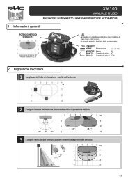
INDICE<br />
1 AVVERTENZE............................................................................................................................................................... 2<br />
2 LAYOUT E COMPONENTI <strong>BRAIN</strong> <strong>18</strong>............................................................................................................................. 2<br />
2.1 IMPOSTAZIONE DI DEFAULT DEGLI INGRESSI............................................................................................................. 2<br />
2.2 DESCRIZIONE COMPONENTI..................................................................................................................................... 3<br />
3 CARATTERISTICHE TECNICHE...................................................................................................................................... 3<br />
4 MORSETTIERE, CONNETTORI, INGRESSI E SEGNALI...................................................................................................... 4<br />
4.1 MORSETTIERA J3 - COLLEGAMENTO ACCESSORI BUS........................................................................................... 4<br />
4.2 MORSETTIERA J4 - INGRESSI SEGNALI................................................................................................................... 4<br />
4.3 MORSETTIERE J5, J8 - OUT1 E OUT2...................................................................................................................... 4<br />
4.4 MORSETTIERA J6 - FINECORSA APERTURA E CHIUSURA.......................................................................................... 4<br />
4.5 MORSETTIERE J7 - ENCODER................................................................................................................................ 5<br />
4.6 MORSETTIERA J9 - LAMPEGGIATORE..................................................................................................................... 5<br />
4.7 MORSETTIERA J10 - ELETTROSERRATURA............................................................................................................... 5<br />
4.8 MORSETTIERA J11, J12 - MOTORI......................................................................................................................... 5<br />
4.9 CONNETTORE J1- ALIMENTAZIONE PRIMARIA DA RETE 230/115 V ........................................................................ 5<br />
4.10 CONNETTORE J2 - ALIMENTAZIONE SECONDARIA................................................................................................. 5<br />
4.11 Connettore J13 - Innesto rapido MODULO RQFZ................................................................................................ 6<br />
4.12 CONNETTORE J14 - INNESTO RAPIDO RICEVENTI 5 PIN......................................................................................... 6<br />
5 COLLEGAMENTI ELETTRICI.......................................................................................................................................... 7<br />
5.1 FOTOCELLULE TRADIZIONALI................................................................................................................................. 7<br />
LAMPEGGIATORE............................................................................................................................................................ 7<br />
ELETTROSERRATURA........................................................................................................................................................ 7<br />
5.2 FOTOCELLULE BUS................................................................................................................................................ 9<br />
5.2.1 INDIRIZZAMENTO FOTOCELLULE BUS............................................................................................................. 9<br />
5.2.2 MEMORIZZAZIONE ACCESSORI...................................................................................................................... 10<br />
6. PROGRAMMAZIONE................................................................................................................................................... 10<br />
6.1. PROGRAMMAZIONE 1° LIVELLO............................................................................................................................ 10<br />
6.2. PROGRAMMAZIONE 2° LIVELLO............................................................................................................................ 12<br />
7. MEMORIZZAZIONE CODIFICA RADIO............................................................................................................................... 17<br />
7.1. MEMORIZZAZIONE DEI RADIOCOMANDI 868 MHz.................................................................................................. 17<br />
7.2. MEMORIZZAZIONE DEI RADIOCOMANDI 433MHz................................................................................................... <strong>18</strong><br />
7.2.1. Memorizzazione remota dei radiocomandi 433 MHz................................................................................... <strong>18</strong><br />
7.3. CANCELLAZIONE DEI CODICI RADIO....................................................................................................................... <strong>18</strong><br />
8 COLLEGAMENTO BATTERIE D’EMERGENZA (OPTIONAL) ............................................................................................. <strong>18</strong><br />
9 MESSA IN FUNZIONE.................................................................................................................................................. 19<br />
9.1 VERIFICA DEI LEDS.................................................................................................................................................... 19<br />
9.2 APPRENDIMENTO TEMPI - SETUP............................................................................................................................ 19<br />
10 PROVA DELL’AUTOMAZIONE....................................................................................................................................... 19<br />
11 SEGNALAZIONE ALLARMI ED ERRORI.......................................................................................................................... 19<br />
12 LOGICHE DI FUNZIONAMENTO................................................................................................................................... 20<br />
11.2 ERRORI................................................................................................................................................................... 20<br />
ITALIANO<br />
DICHIARAZIONE CE DI CONFORMITÁ<br />
Fabbricante: GENIUS S.p.A.<br />
Indirizzo: Via P. Elzi, 32 - 24050 Grassobbio Bergamo - ITALIA<br />
Dichiara che: L’apparecchiatura elettronica <strong>BRAIN</strong> <strong>18</strong><br />
• ·è conforme ai requisiti essenziali di sicurezza delle seguenti direttive CEE<br />
2006/95/CE Direttiva Bassa Tensione<br />
2004/108/CE Direttiva Compatibilità Elettromagnetica<br />
Nota aggiuntiva:<br />
Questo prodotto è stato sottoposto a test in una configurazione tipica<br />
omogenea (tutti prodotti di costruzione GENIUS S.p.A.).<br />
Grassobbio, 01 - 03 - 2011<br />
L’Amministratore Delegato<br />
Enrico Nardi<br />
AVVERTENZE<br />
• Attenzione! È importante per la sicurezza delle persone seguire attentamente tutta l’istruzione.<br />
• Una errata installazione o un errato uso del prodotto può portare a gravi danni alle persone.<br />
• Leggere attentamente le istruzioni prima di iniziare l’installazione del prodotto e conservarle per riferimenti futuri.<br />
• Il simbolo evidenzia le note importanti per la sicurezza delle persone e l’integrità dell’automazione.<br />
• Il simbolo richiama l’attenzione sulle note riguardanti le caratteristiche od il funzionamento del prodotto.<br />
1
1 AVVERTENZE<br />
ITALIANO<br />
Attenzione: Prima di effettuare qualsiasi tipo di intervento sull’apparecchiatura elettronica (collegamenti, manutenzione)<br />
togliere sempre l’alimentazione elettrica.<br />
- Prevedere a monte dell’impianto un interruttore magnetotermico differenziale con adeguata soglia di intervento.<br />
- Collegare il cavo di terra all’apposito morsetto.<br />
- Separare sempre i cavi di alimentazione da quelli di comando e di sicurezza (pulsante, ricevente, fotocellule, ecc.). Per<br />
evitare qualsiasi disturbo elettrico utilizzare guaine separate o cavo schermato (con schermo collegato a massa).<br />
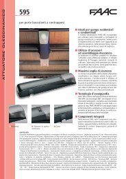
2 LAYOUT E COMPONENTI <strong>BRAIN</strong> <strong>18</strong><br />
J14<br />
J2<br />
DL14<br />
SW1<br />
DL15<br />
J1<br />
J13<br />
LCD<br />
SW2<br />
DL16<br />
DL17<br />
DL19<br />
SW7<br />
SW3<br />
DL20<br />
DL<strong>18</strong><br />
SW4<br />
SW5<br />
SW6<br />
DL12<br />
DL13<br />
DL1<br />
DL2<br />
DL3<br />
DL4<br />
DL5<br />
J5<br />
DL6<br />
DL7<br />
DL8<br />
DL9<br />
DL10<br />
DL11<br />
J8 J9 J10 J11<br />
J12<br />
J3<br />
J4<br />
J6<br />
J7<br />
Fig. 1<br />
2.1 IMPOSTAZIONE DI DEFAULT DEGLI INGRESSI<br />
Morsettiera J4<br />
IN1 OPEN A contatto N.A.<br />
IN2 OPEN B contatto N.A.<br />
IN3 STOP contatto N.C.<br />
IN4 FSW OP contatto N.C.<br />
IN5 FSW CL contatto N.C.<br />
Connettore J13 - Modulo RQFZ<br />
Canale 1<br />
OPEN A<br />
Canale 2<br />
OPEN B<br />
Connettore J14 - Radio<br />
Canale 1 RP<br />
OPEN A<br />
Canale 2 RP2<br />
OPEN B<br />
2
2.2 DESCRIZIONE COMPONENTI<br />
LCD<br />
SW1<br />
SW2<br />
SW3<br />
DISPLAY DI SEGNALAZIONE E PROGRAMMAZIONE<br />
PULSANTE PROGRAMMAZIONE “R1”<br />
PULSANTE PROGRAMMAZIONE “R2”<br />
PULSANTE DI “SETUP”<br />
SW4 PULSANTE PROGRAMMAZIONE “+”<br />
SW5 PULSANTE PROGRAMMAZIONE “-”<br />
SW6<br />
SW7<br />
DL1<br />
DL2<br />
DL3<br />
DL4<br />
DL5<br />
DL6<br />
DL7<br />
DL8<br />
DL9<br />
DL10<br />
DL11<br />
DL12<br />
DL13<br />
DL14<br />
DL15<br />
PULSANTE PROGRAMMAZIONE “F”<br />
PULSANTE DI RESET SOFTWARE “RESET SW”<br />
LED DI CONTROLLO STATO INGRESSO “IN1”<br />
LED DI CONTROLLO STATO INGRESSO “IN2”<br />
LED DI CONTROLLO STATO INGRESSO “IN3”<br />
LED DI CONTROLLO STATO INGRESSO “IN4”<br />
LED DI CONTROLLO STATO INGRESSO “IN5”<br />
LED DI CONTROLLO STATO INGRESSO “FCA1”<br />
LED DI CONTROLLO STATO INGRESSO “FCC1”<br />
LED DI CONTROLLO STATO INGRESSO “FCA2”<br />
LED DI CONTROLLO STATO INGRESSO “FCC2”<br />
LED DI CONTROLLO STATO INGRESSO “ENC1”<br />
LED DI CONTROLLO STATO INGRESSO “ENC2”<br />
LED DI SEGNALAZIONE DISPOSITIVO A BUS ATTIVO<br />
LED DI SEGNALAZIONE DIAGNOSTICA BUS<br />
LED DI SEGNALAZIONE PRESENZA ALIMENTAZIONE PRIMARIA<br />
LED DI SEGNALAZIONE ALIMENTAZIONE SECONDARIA<br />
(Vedi cap. 8)<br />
DL16 LED DI SEGNALAZIONE PULSANTE “SW1” (PULSANTE R1)<br />
DL17 LED DI SEGNALAZIONE PULSANTE “SW2” (PULSANTE R2)<br />
DL<strong>18</strong><br />
DL19<br />
DL20<br />
J1<br />
J2<br />
J3<br />
LED DI SEGNALAZIONE PULSANTE “SW3” (PULSANTE SETUP)<br />
LED DI SEGNALAZIONE PRESSIONE PULSANTE “RESET SW”<br />
LED DI SEGNALAZIONE DI ALLARME “ALARM”<br />
CONNETTORE ALIMENTATORE SWITCHING (ALIM. PRIMARIA)<br />
CONNETTORE ALIMENTAZIONE SECONDARIA<br />
CONNETTORE COLLEGAMENTO DISPOSITIVI BUS<br />
J4 CONNETTORE INGRESSI IN MORSETTIERA (vedi cap. 3.1)<br />
J5<br />
J6<br />
CONNETTORE USCITA OUT2 (vedi progr. 2° liv.)<br />
CONNETTORE INGRESSI FINECORSA<br />
J7 CONNETTORE INGRESSI ENCODER ANTA 1 ED ANTA 2<br />
J8<br />
J9<br />
J10<br />
CONNETTORE USCITA OUT1 (vedi progr. 2° liv.)<br />
CONNETTORE USCITA LAMPEGGIATORE<br />
CONNETTORE USCITA ELETTROSERRATURA<br />
J11 CONNETTORE MOTORE ANTA 1<br />
J12 CONNETTORE MOTORE ANTA 2<br />
J13<br />
J14<br />
CONNETTORE MODULO RICEVENTE RQFZ<br />
CONNETTORE RICEVENTI 5 PIN<br />
Led ALARM lampeggiante indica allarme in<br />
corso (situazione non pregiudicante il funzionamento<br />
del cancello)<br />
ITALIANO<br />
3 CARATTERISTICHE TECNICHE<br />
Led ALARM acceso fisso indica errore in corso<br />
(situazione che blocca il funzionamento fino<br />
alla eliminazione della causa dell’errore)<br />
Alimentazione<br />
primaria da rete<br />
Alimentazione<br />
secondaria<br />
Potenza assorbita<br />
da rete<br />
Carico max.<br />
per motore<br />
Alimentazione<br />
accessori<br />
Corrente max<br />
accessori<br />
Corrente ricarica<br />
batteria<br />
Temperatura di funzoinamento<br />
Fusibili di protezione<br />
apparecchiatura<br />
Fusibile di protezione<br />
alimentatore<br />
Logiche di<br />
funzionamento<br />
con alimentatore switching<br />
230/115 V~ - 50/60 Hz<br />
24 Vdc - 16 A max.<br />
(min. 20 Vdc. - max. 28 Vdc.)<br />
stand-by = 4W<br />
max. ~ 400 W<br />
7 A<br />
24 Vdc<br />
24Vdc max 500 mA<br />
BUS-2EASY max 500 mA<br />
<strong>18</strong>0 mA<br />
(-20 ÷ +55) °C<br />
Tutti autoripristinanti<br />
2.5 A<br />
Semiautomatica, Automatica, Semiautomatica<br />
“passo-passo“, Automatica con<br />
inversione in pausa, Automatica “passopasso”,<br />
Automatica Sicurezze, Automatica<br />
Sicurezze “passo-passo“, Semiautomatica<br />
“b”, Logica mista “bC”, Uomo<br />
presente, Automatica con funzione timer.<br />
Tempo di lavoro<br />
Tempo di pausa<br />
Forza motore<br />
Velocità motore<br />
Ingressi in connettore<br />
Programmabile (da 0 a 9min 50 sec)<br />
Programmabile (da 0 a 9min 50 sec)<br />
Programmabile su 50 livelli<br />
Programmabile su 10 livelli<br />
Alimentatore Switching, Batteria, riceventi<br />
5 pin, modulo RQFZ<br />
Ingressi in morsettiera BUS, Ingressi da IN1 a IN5 (vedi par. 4),<br />
Finecorsa, Encoder.<br />
Uscite in morsettiera Lampeggiatore, Motori, Elettroserratura,<br />
OUT1, OUT2 (programmabili), Alimentazione<br />
accessori<br />
Programmazione 1° e 2° liv. con n° 3 tasti (+, -, F) e display<br />
LCD.<br />
3
ITALIANO<br />
4 MORSETTIERE, CONNETTORI, INGRESSI E SEGNALI<br />
4.1 MORSETTIERA J3 - COLLEGAMENTO ACCESSORI BUS<br />
Morsetto per il collegamento degli accessori BUS-2EASY. Vedi<br />
par. 5.2.<br />
4.2 MORSETTIERA J4 - INGRESSI SEGNALI<br />
Collegamento di 2 contatti N.A. in parallelo<br />
Se non vengono collegati dispositivi di sicurezza<br />
in apertura, ponticellare i morsetti IN4 e GND<br />
se la sicurezza FOTEST non è attiva, altrimenti<br />
ponticellare IN4 e -OUT1.<br />
IN5 - Contatto sicurezze in chiusura (N.C. - morsetto 7): vedi<br />
paragrafo 5.1.<br />
Per installare più dispositivi di sicurezze in chiusura<br />
collegare i contatti N.C. in serie<br />
Collegamento di 2 contatti N.C. in serie<br />
Fig. 2<br />
Fig. 3<br />
IN1 - OPEN A - Comando di “Apertura” (N.A. - morsetto<br />
1): si intende qualsiasi datore d’impulso (es.: pulsante) che,<br />
chiudendo un contatto, comanda un OPEN TOTALE.<br />
Per installare più datori d’impulso d’apertura<br />
totale, collegare i contatti N.A. in parallelo<br />
Altre possibilità di programmazione, più dettagliate,<br />
sono possibili tramite programmazione<br />
con PC (vedi istruzioni dedicate).<br />
IN2 - OPEN B - Comando di “Apertura Parziale” (N.A. - morsetto<br />
3): si intende qualsiasi datore d’impulso (es.: pulsante) che,<br />
chiudendo un contatto, comanda un OPEN PARZIALE.<br />
In impianti a doppia anta l’OPEN B comanda<br />
un’apertura dell’anta 1 (motore 1) pari al 100%<br />
della sua apertura totale<br />
Per installare più datori d’impulso d’apertura<br />
parziale, collegare i contatti N.A. in parallelo<br />
Selezionando una delle seguenti logiche (b,<br />
bC, C), l’ingresso IN2 automaticamente diventa<br />
CLOSE (N.A.).<br />
IN3 - Comando Contatto di STOP (N.C. - morsetto 4): si<br />
intende qualsiasi dispositivo (es.: pulsante) che aprendo un<br />
contatto può arrestare il moto dell’automazione.<br />
Per installare più dispositivi di STOP collegare i<br />
contatti N.C. in serie.<br />
Se non vengono collegati dispositivi di sicurezza<br />
in chiusura, ponticellare i morsetti IN5<br />
e GND se la sicurezza FOTOTEST non è attiva,<br />
altrimenti ponticellare IN5 e -OUT1.<br />
GND - (morsetti 2-6): Negativo alimentazione accessori<br />
+24 - (morsetto 8): Positivo alimentazione accessori<br />
Il carico max. degli accessori è di 500mA suddiviso<br />
fra le morsettiere J4 e J7. Per calcolare<br />
l’assorbimento massimo fare riferimento alle<br />
istruzioni dei singoli accessori.<br />
4.3 MORSETTIERE J5, J8 - OUT1 E OUT2<br />
E’ possibile impostare le due uscite in una delle funzioni descritte<br />
in Programmazione 2° Livello (vedi par. 6.2.). Il valore<br />
di default è:<br />
OUT1 = SEMPRE ATTIVA<br />
OUT2 = LAMPADA SPIA.<br />
Massimo carico applicabile su ciascuna uscita:<br />
24 Vdc con 100 mA.<br />
4.4 MORSETTIERA J6 - FINECORSA APERTURA E CHIUSURA<br />
Morsettiera per il collegamento dei finecorsa di apertura (FCA1<br />
e FCA2) e chiusura (FCC1 e FCC2).<br />
I contatti di finecorsa FCC1, FCA1, FCC2, FCA2<br />
sono tutti contatti NC. Vedere programmazione<br />
di 2° livello per le diverse configurazioni<br />
applicabili agli ingressi finecorsa.<br />
Se non vengono utilizzati non occorre ponticellare<br />
i contatti di finecorsa FCC1, FCA1,<br />
FCC2, FCA2<br />
Altre possibilità di programmazione, più dettagliate,<br />
sono possibili tramite programmazione<br />
con PC (vedi istruzioni dedicate).<br />
Se non vengono collegati dispositivi di stop,<br />
ponticellare i morsetti STOP e GND.<br />
IN4 - Contatto sicurezze in apertura (N.C. - morsetto 5): vedi<br />
paragrafo 5.1.<br />
Per installare più dispositivi di sicurezze in apertura<br />
collegare i contatti N.C. in serie.<br />
4
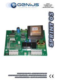
4.5 MORSETTIERE J7 - ENCODER<br />
E’ possibile collegare a questa morsettiera degli encoder<br />
con segnale open collector riferito a massa (es. Timecoder)<br />
per rilevare la posizione angolare dell’anta. Per effettuare i<br />
cablaggi seguire la fig. 4.<br />
La configurazione indicata nel disegno è<br />
quella massima. È possibile utilizzare solo 1<br />
Timecoder. In questo caso non occorre ponticellare<br />
a massa gli ingressi non utilizzati<br />
4.9 CONNETTORE J1- ALIMENTAZIONE PRIMARIA DA RETE<br />
230/115 V<br />
J1: Selezionare l’alimentazione corretta posizionando il selettore<br />
dell’alimentatore switching nella posizione corretta.<br />
(default 230 Vac.)<br />
ITALIANO<br />
I tempi di riconoscimento ostacolo e battuta di<br />
default sono rispettivamente 2 e 4 secondi.<br />
115 Vac<br />
230 Vac<br />
BIANCO<br />
BIANCO<br />
ROSSO<br />
NERO<br />
ROSSO<br />
NERO<br />
Fig. 4<br />
Fig. 5<br />
Per un corretto funzionamento è obbligatorio<br />
il collegamento dell’alimentatore switching<br />
al conduttore di terra presente nell’impianto.<br />
Prevedere a monte del sistema un adeguato<br />
interruttore magnetotermico differenziale.<br />
4.6 MORSETTIERA J9 - LAMPEGGIATORE<br />
Uscita per lampeggiatore a 24Vdc<br />
Massimo carico applicabile: 24 Vdc - 15 W<br />
4.7 MORSETTIERA J10 - ELETTROSERRATURA<br />
Uscita per elettroserratura a 12 Vac o 24Vdc<br />
4.8 MORSETTIERA J11, J12 - MOTORI<br />
J11 (MOT1): Connessione del motore collegato all’anta 1,<br />
ovvero l’anta che durante un’apertura si apre per prima.<br />
J12 (MOT2): Connessione del motore collegato all’anta 2,<br />
ovvero l’anta che apre per seconda.<br />
Se viene collegato un solo motore, deve essere<br />
collegato al morsetto J11 (MOT1).<br />
Se durante la prima movimentazione della<br />
procedura di SETUP, le ante aprono invece<br />
di chiudere è necessario invertire i cavi di<br />
collegamento dei motori.<br />
4.10 CONNETTORE J2 - ALIMENTAZIONE SECONDARIA<br />
J2: In assenza dell’alimentazione primaria da rete è possibile<br />
alimentare l’apparecchiatura elettronica tramite un’alimentazione<br />
secondaria a bassa tensione (24 Vdc). L’alimentazione<br />
può essere fornita tramite un pacco batterie,<br />
ricaricate tramite un apposito carica batterie integrato<br />
sulla scheda, oppure tramite un alimentatore stabilizzato.<br />
In entrambi i casi l’alimentazione deve avere le seguenti<br />
caratteristiche:<br />
Tensione: (24 ± 4) Vdc<br />
Corrente: 16 A max.<br />
Nel caso si utilizzi un alimentatore stabilizzato<br />
esterno è necessario disabilitare la funzione<br />
“carica batterie” tramite PC (vedi istruzioni<br />
dedicate).<br />
5
4.11 CONNETTORE J13 - INNESTO RAPIDO MODULO RQFZ<br />
ITALIANO<br />
L’apparecchiatura elettronica è provvista di un sistema di<br />
decodifica bi-canale integrato. Questo sistema permette<br />
di memorizzare, tramite un modulo ricevente aggiuntivo<br />
RQFZ433 o RQFZ868 (Fig. 6 rif. ), radiocomandi della stessa<br />
frequenza. È possibile memorizzare sia l’apertura totale (OPEN<br />
A) sia l’apertura parziale (OPEN B) dell’automazione fino ad un<br />
massimo di 256 canali.<br />
Per la memorizzazione dei radiocomandi fare<br />
riferimento al Cap. 7.<br />
Il 2° canale (di default OPEN B ) può cambiare<br />
funzione associato all’attivazione di una uscita<br />
programmabile. ( vedi prog. 2°LIVELLO o1e<br />
o2parametro 14 - 15)<br />
Inserimento e disinserimento delle schede<br />
devono essere effettuati solo dopo aver tolto<br />
tensione.<br />
a<br />
Fig. 6<br />
4.12 CONNETTORE J14 - INNESTO RAPIDO RICEVENTI 5 PIN<br />
E’ utilizzato per la connessione rapida di riceventi a 5 pin.<br />
Nel caso si utilizzi una ricevente bicanale sarà possibile comandare<br />
direttamente due differenti canali radio, l’OPEN A e<br />
l’OPEN B dell’automazione, da un radiocomando bicanale.<br />
Nel caso si utilizzi una ricevente monocanale sarà possibile<br />
comandare solamente un canale radio, l’OPEN A.<br />
Innestare l’accessorio con il lato componenti rivolto verso<br />
l’interno della scheda.<br />
Inserimento e disinserimento delle schede vanno<br />
effettuati SOLO dopo aver tolto tensione.<br />
Esempio di collegamento<br />
di accessorio radio<br />
J14<br />
Fig. 7<br />
6
5 COLLEGAMENTI ELETTRICI<br />
Da abilitare nel 2°<br />
livello di programmazione<br />
* *<br />
LAMPEGGIATORE<br />
ELETTROSERRATURA<br />
ITALIANO<br />
Per il collegamento<br />
delle<br />
fotocellule e dei<br />
dispositivi di sicurezza,<br />
riferirsi al<br />
paragrafo 5.1.<br />
Da utilizzare<br />
con motori sprovvisti<br />
di encoder a BUS<br />
(vedi par. 4.5)<br />
*<br />
Carico max 24Vdc - 500mA<br />
Con l’apparecchiatura elettronica <strong>BRAIN</strong> <strong>18</strong> si possono<br />
utilizzare dispositivi fotocellule di tipo tradizionale (contatto<br />
N.C. a relay) e/o fotocellule a BUS (contatto open collector).<br />
Il posizionamento delle fotocellule ed il loro funzionamento è<br />
schematizzato in Fig. 9.<br />
Collegamento 1 coppia di fotocellule in chiusura<br />
con sicurezza FOTOTEST attivata<br />
Fig. 8<br />
Impostare nel secondo livello di programmazione o1 = 01<br />
5.1 FOTOCELLULE TRADIZIONALI<br />
Prima di collegare le fotocellule è opportuno sceglierne il tipo<br />
di funzionamento in base alla zona di movimento che devono<br />
proteggere:<br />
Sicurezze in chiusura: intervengono soltanto durante il movimento<br />
di chiusura dell’automazione, quindi sono adatte<br />
a proteggere la zona di chiusura dal rischio di impatto.<br />
Sicurezze in apertura: intervengono soltanto durante il movimento<br />
di apertura dell’automazione, quindi sono adatte<br />
a proteggere la zona di apertura dal rischio di impatto.<br />
Sicurezze in apertura/chiusura: intervengono sia durante<br />
il movimento di apertura e chiusura dell’automazione,<br />
quindi sono adatte a proteggere tutta la zona di movimentazione<br />
dal rischio di impatto.<br />
Altre sicurezze<br />
Collegamento 1 coppia di fotocellule in chiusura<br />
con sicurezza FOTOTEST e STOP disattivata<br />
Sicurezze in apertura/chiusura<br />
Fig. 9<br />
Altre sicurezze<br />
Sicurezze in chiusura<br />
Sicurezze in<br />
apertura<br />
7<br />
Fig. 10
Collegamento di due coppie di fotocellule in chiusura<br />
Collegamento di una coppia di fotocellule in chiusura, una<br />
in apertura ed una in apertura/chiusura<br />
ITALIANO<br />
Altre sicurezze<br />
f<br />
h<br />
f<br />
h<br />
f<br />
h<br />
f<br />
h<br />
Fig. 11<br />
Collegamento 1 coppia di fotocellule in apertura<br />
f<br />
h<br />
Fig. 15<br />
Collegamento di una coppia di fotocellule in apertura<br />
ed una in chiusura<br />
Altre sicurezze<br />
f<br />
h<br />
Fig. 12<br />
Collegamento di un dispositivo di sicurezza in chiusura e di un<br />
dispositivo di sicurezza in apertura<br />
f<br />
h<br />
f<br />
h<br />
Fig. 13<br />
Fig. 16<br />
Collegamento di nessun dispositivo di sicurezza e stop<br />
Collegamento di una coppia di fotocellule in chiusura<br />
ed una in apertura/chiusura<br />
Fig. 14<br />
Nel caso non si utilizzi la sicurezza FOTOTEST<br />
occorre collegare l’alimentazione dei trasmettitori<br />
ai morsetti 6 e 8 di J4.<br />
Utilizzando la sicurezza FOTOTEST collegare<br />
l’alimentazione dei trasmettitori all’OUT1 dopo<br />
averla impostata opportunamente (vedi programmazione<br />
di 2° livello e fig. 10).<br />
Utilizzando la sicurezza FOTOTEST anche gli<br />
ingressi di sicurezza non utilizzati andranno<br />
ponticellati col negativo di OUT1 (vedi Fig.<br />
10).<br />
8<br />
f<br />
h<br />
f<br />
h<br />
Fig. 17
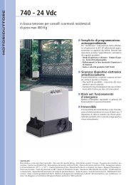
5.2 FOTOCELLULE BUS<br />
Questa scheda è provvista di circuito BUS che consente di<br />
collegare facilmente un elevato numero di dispositivi BUS<br />
ausiliari alla sicurezza (ad es. fino a 16 coppie di fotocellule),<br />
opportunamente programmati, utilizzando solamente due<br />
cavi senza polarità.<br />
Prima di collegare le fotocellule è opportuno sceglierne il tipo<br />
di funzionamento (Fig. <strong>18</strong>) in base alla zona di movimento che<br />
devono proteggere e posizionare, sia sul trasmettitore e sia<br />
sul ricevitore, i dip switch come da Tab. 1:<br />
Fotocellule in chiusura: intervengono soltanto durante il<br />
movimento di chiusura dell’automazione, quindi sono<br />
adatte a proteggere la zona di chiusura dal rischio di<br />
impatto.<br />
Se occorre collegare due o più fotocellule a<br />
BUS in chiusura scegliere indirizzi diversi per<br />
ogni coppia utilizzata.<br />
Fotocellule in apertura: intervengono soltanto durante il<br />
movimento di apertura dell’automazione, quindi sono<br />
adatte a proteggere la zona di apertura dal rischio<br />
di impatto.<br />
Se occorre collegare due o più fotocellule a<br />
BUS in apertura scegliere indirizzi diversi per<br />
ogni coppia utilizzata.<br />
Fotocellule in apertura/chiusura: intervengono durante il<br />
movimento di chiusura e apertura dell’automazione,<br />
quindi sono adatte a proteggere tutta la zona di movimentazione<br />
dal rischio di impatto.<br />
Se occorre collegare due o più fotocellule<br />
a BUS in chiusura/apertura scegliere codici<br />
diversi per ogni coppia utilizzata.<br />
Datori di impulso: utilizzate come datori di impulso per<br />
l’apertura dell’automazione.<br />
In fig. <strong>18</strong> è rappresentato un’automazione a battente 2 ante<br />
con indicati i fasci di copertura delle fotocellule:<br />
A: Fotocellule con intervento in APERTURA e CHIUSURA<br />
B: Fotocellule con intervento in APERTURA<br />
C: Fotocellule con intervento in APERTURA<br />
D: Fotocellule con intervento in CHIUSURA<br />
5.2.1 INDIRIZZAMENTO FOTOCELLULE BUS<br />
RX<br />
È importante dare sia al trasmettitore che al<br />
ricevitore lo stesso indirizzo.(medesimo settaggio<br />
DIP-SWITCH)<br />
Accertarsi che non vi siano due o più coppie<br />
di fotocellule con lo stesso indirizzo.(medesimo<br />
settaggio DIP-SWITCH)<br />
Se non si utilizza alcun accessorio BUS, lasciare<br />
libero il connettore BUS (J3 - fig. 1).<br />
TX<br />
In Tab. 1 sono riportate le programmazioni del dip-switch<br />
presente all’interno del trasmettitore e del ricevitore delle fotocellule<br />
BUS.<br />
Tab. 1 - Indirizzamento fotocellule BUS<br />
DL1 = Allineamento<br />
DL2 = Stato BUS /<br />
Alimentazione<br />
DS1 = Dip-switches<br />
per la programmazione<br />
Dip1 Dip2 Dip3 Dip4 Rif. Tipologia<br />
Fig. 19<br />
ITALIANO<br />
OFF OFF OFF OFF<br />
Alla scheda possono essere collegati fino ad un massimo di<br />
16 coppie di fotocellule BUS.<br />
Le fotocellule sono suddivise in gruppi:<br />
Fotocellule in apertura: max 6<br />
Fotocellule in chiusura: max 7<br />
Fotocellule in apertura/chiusura: max 2<br />
Fotocellula usata come impulso OPEN: max 1<br />
OFF OFF OFF ON<br />
OFF OFF ON OFF<br />
OFF OFF ON ON<br />
OFF ON ON OFF<br />
OFF ON ON ON<br />
ON OFF OFF OFF<br />
B - C<br />
APERTURA<br />
ON OFF OFF ON<br />
ON OFF ON OFF<br />
ON OFF ON ON<br />
D<br />
CHIUSURA<br />
ON ON OFF OFF<br />
ON ON OFF ON<br />
ON ON ON OFF<br />
OFF ON OFF OFF<br />
OFF ON OFF ON<br />
A<br />
APERTURA e<br />
CHIUSURA<br />
ON ON ON ON / IMPULSO OPEN<br />
Fig. 24<br />
9
ITALIANO<br />
5.2.2 MEMORIZZAZIONE ACCESSORI<br />
In qualsiasi momento è possibile aggiungere accessori BUS<br />
all’impianto, semplicemente seguendo la seguente procedura:<br />
1. Installare e programmare gli accessori con l’indirizzo desiderato<br />
(vedi par. 5.2.1).<br />
2. Togliere alimentazione alla scheda.<br />
3. Collegare i due cavi degli gli accessori BUS alla morsettiera<br />
rossa J3 (polarità indifferente).<br />
4. Alimentare la scheda, avendo cura di collegare prima il<br />
connettore J1 dell’alimentazione principale (proveniente<br />
dall’alimentatore switching) ed in seguito il connettore J2<br />
delle eventuali batterie.<br />
5. Premere rapidamente una volta il pulsante SETUP (SW3) per<br />
eseguire l’apprendimento. Verificare il funzionamento dei<br />
dispositivi a BUS installati.<br />
La scheda ha memorizzato gli accessori BUS. Seguire le indicazione<br />
della tabella seguente per controllare il buono stato<br />
del collegamento BUS.<br />
Tab. 2 - Descrizione led DL12 (ROSSO)<br />
Dispositivo di sicurezza impegnato o datore<br />
di impulso attivo<br />
Acceso<br />
Spento NESSUN dispositivo di sicurezza impegnato<br />
e NESSUN datore di impulso attivo<br />
Tab. 3 - Descrizione led DL13 (VERDE)<br />
Acceso fisso<br />
Normale attività (led acceso anche in<br />
assenza di fotocellule)<br />
Spento Linea BUS in cortocircuito (flash ogni 2,5<br />
sec.)<br />
Lampeggiante<br />
veloce<br />
Rilevato errore nel collegamento BUS,<br />
ripetere la procedura di acquisizione. Se<br />
l’errore si ripresenta controllare che nell’impianto<br />
non ci sia più di un accessorio<br />
con lo stesso indirizzo (vedi anche istruzioni<br />
relativa agli accessori)<br />
Se premendo il tasto F (e mantenendolo pre<br />
muto), sul display appare dF , significa che<br />
si è entrati nella programmazione di 1° Livello<br />
(vedere par. 6.1).<br />
La modifica dei parametri di programmazione<br />
diventa immediatamente efficace,<br />
mentre la memorizzazione definitiva avviene<br />
solo all’uscita dalla programmazione ed al<br />
ritorno alla visualizzazione dello stato degli<br />
ingessi. Se si toglie alimentazione all’apparecchiatura<br />
prima del ritorno alla visualizzazione<br />
dello stato degli ingressi, tutte le variazioni<br />
effettuate verranno perse.<br />
È possibile ritornare alla visualizzazione dello<br />
stato degli ingressi, e memorizzare tutti i parametri<br />
modificati fino a quel momento, da<br />
qualsiasi punto della programmazione di 1° e<br />
2° livello premendo contemporaneamente i<br />
tasti F e -.<br />
Per ripristinare le impostazioni di default è<br />
sufficiente ricaricare il default desiderato nel<br />
primo passaggio della programmazione di 1°<br />
livello.<br />
6.1. PROGRAMMAZIONE 1° LIVELLO<br />
Se premendo un qualsiasi pulsante sul display appare PC<br />
significa che sulla scheda è caricata una programmazione<br />
da PC con password di protezione. Non è possibile modificare<br />
nulla senza PC e relativa password di protezione.<br />
Per accedere alla programmazione di 1° livello occorre premere<br />
il pulsante F.<br />
• Se premendo il tasto F (e mantenendolo premuto) sul<br />
display appare il nome della funzione.<br />
• Rilasciando il pulsante, il display visualizza il valore della<br />
funzione che può essere modificato con i tasti + e -.<br />
• Premendo nuovamente F (e mantenendolo premuto) il<br />
display mostra il nome della funzione successiva, ecc.<br />
• Arrivati all’ultima funzione, la pressione del pulsante F<br />
provoca l’uscita dalla programmazione e il salvataggio<br />
dei parametri. Il display riprende a visualizzare lo stato<br />
dell’automazione.<br />
6. PROGRAMMAZIONE<br />
Per programmare il funzionamento dell’automazione è necessario<br />
accedere alla modalità “PROGRAMMAZIONE”.<br />
La programmazione si divide in due parti: 1° LIVELLO, 2° LIVEL-<br />
LO<br />
All’accensione della scheda compare sul display<br />
bo e per 3 secondi la versione fw della<br />
scheda.<br />
Normalmente sul display è visualizzato lo stato<br />
dell’automazione. Alla pressione del pulsante<br />
F se sul display appare PC significa che sulla<br />
scheda è caricata una programmazione effettuata<br />
da PC; se non è impostata una password<br />
è possibile modificare solo i parametri Lo-PA-<br />
Pb. Per poter accedere agli altri parametri di<br />
programmazione occorre ricaricare il default<br />
relativo al motore utilizzato (in questo caso la<br />
programmazione da PC verrà sostituita con i<br />
parametri di default della scheda)<br />
10
PROGRAMMAZIONE 1° LIVELLO<br />
Display Funzione Default 0 Default 1 Default 2 Default 4<br />
dF<br />
0 1 2 4<br />
MO<br />
LO<br />
PA<br />
DEFAULT:<br />
0 Configura i parametri con valori di DEFAULT corrispondenti ad una<br />
installazione con operatori non GENIUS. (vedere colonna default 0).<br />
1 Configura i parametri con valori di DEFAULT corrispondenti ad una<br />
installazione con operatori GENIUS EUROBAT/G-BAT/MISTRAL/SIROC-<br />
CO/ROLLER/TRIGON (vedere colonna default 1).<br />
2 Configura i parametri con valori di DEFAULT corrispondente ad una<br />
installazione con operatori GENIUS COMPAS (vedere colonna default<br />
2).<br />
3 NON UTILIZZATO<br />
4 Configura i parametri con valori di DEFAULT corrispondenti ad una<br />
installazione con operatori ENV (G-BAT ENV/MISTRAL ENV), vedere<br />
colonna default 4.<br />
5 NON UTILIZZATO<br />
CU<br />
PC<br />
Se rilasciando il pulsante F appare il valore CU significa che è<br />
stata selezionata una configurazione standard modificata tramite<br />
pulsanti e display. Se si vuole mantenere tale programmazione<br />
premere nuovamente il pulsante F.<br />
Se rilasciando il pulsante F appare il valore PC significa che è stata<br />
effettuata una programmazione da PC con password di default<br />
(0000). Premendo i tasti + e - è possibile caricare una configurazione<br />
di default fra quelle sopra elencate. Se si vuole mantenere la<br />
programmazione da PC premere nuovamente il pulsante F.<br />
TIPO MOTORE:<br />
00 operatori non Genius.<br />
01 operatori Genius Eurobat/G.Bat/Mistral/Sirocco/Roller/Trigon.<br />
02 operatori Genius Compas.<br />
03 Non utilizzato<br />
04 Non utilizzato<br />
05 Non utilizzato<br />
Parametro di sola visualizzazione non modificabile<br />
LOGICHE DI FUNZIONAMENTO:<br />
E Semiautomatica.<br />
EP Semiautomatica “Passo a passo”.<br />
S Automatica “Sicurezze”.<br />
SA Automatica con inversione in pausa.<br />
SP Automatica “Sicurezze Passo a passo”.<br />
A1 Automatica 1.<br />
A Automatica.<br />
AP Automatica “Passo a passo”.<br />
At Automatica con funzione timer.<br />
b Semiautomatica “b”.<br />
bC Mista (AP ad impulso/ CH ad uomo presente)<br />
C Uomo presente.<br />
Custom.<br />
CU<br />
TEMPO DI PAUSA A:<br />
Il tempo di pausa a fronte di un comando di apertura TOTALE. Ha effetto<br />
solamente se è stata selezionata una logica con tempo pausa. Regolabile<br />
da 0 a 59 sec. a passi di un secondo.<br />
In seguito la visualizzazione cambia in minuti e decine di secondi (separati<br />
da un punto) e il tempo si regola a passi di 10 secondi, fino al valore massimo<br />
di 9.5 minuti.<br />
ES: se il display indica 2.5, il tempo di pausa corrisponde a 2 min. e 50 sec.<br />
00 01 02 04<br />
E E E E<br />
20 20 20 20<br />
ITALIANO<br />
11
ITALIANO<br />
PROGRAMMAZIONE 1° LIVELLO<br />
Display Funzione Default 0 Default 1 Default 2 Default 4<br />
Pb 20 20 20 20<br />
F1<br />
F2<br />
SP<br />
TEMPO DI PAUSA B:<br />
Il tempo di pausa a fronte di un comando di apertura PARZIALE. Ha effetto<br />
solamente se è stata selezionata una logica con tempo pausa. Regolabile<br />
da 0 a 59 sec. a passi di un secondo.<br />
In seguito la visualizzazione cambia in minuti e decine di secondi (separati<br />
da un punto) e il tempo si regola a passi di 10 secondi, fino al valore massimo<br />
di 9.5 minuti.<br />
ES: se il display indica 2.5, il tempo di pausa corrisponde a 2 min. e 50 sec.<br />
FORZA MOTORE 1:<br />
Regola il livello di forza massima del motore 1.<br />
01 = forza minima<br />
50 = forza massima<br />
Variando il valore della forza è consigliabile eseguire un nuovo<br />
SETUP (vedi par. 9.1)<br />
FORZA MOTORE 2:<br />
Regola il livello di forza massima del motore 2.<br />
01 = forza minima<br />
50 = forza massima<br />
Variando il valore della forza è consigliabile eseguire un nuovo<br />
SETUP (vedi par. 9.1)<br />
VELOCITÀ:<br />
Regola la velocità di movimentazione dei motori. Sono previsti 10 livelli. Il<br />
valore è relativo e non assoluto in quanto il valore di velocità è riferito al<br />
peso dell’anta rilevato durante il ciclo di SETUP.<br />
25 25 25 40<br />
25 25 25 40<br />
08 08 08 08<br />
rL<br />
01 = velocità minima<br />
10 = velocità massima<br />
RALLENTAMENTO:<br />
Regola lo spazio di rallentamento come percentuale della corsa totale<br />
delle ante. Regolabile da 00 fino a 99 %. a passi di 1%.<br />
30 30 30 20<br />
St<br />
00 = nessun rallentamento<br />
01 = spazio rallentamento minimo<br />
99 = spazio rallentamento massimo<br />
STATO DELL’AUTOMAZIONE:<br />
Uscita dalla programmazione, memorizzazione dei dati e ritorno alla visualizzazione dello stato dell’automazione<br />
00 = CHIUSO<br />
01 = APERTO<br />
02 = Fermo poi “APRE”<br />
03 = Fermo poi “CHIUDE”<br />
04 = In “PAUSA”<br />
05 = In fase di apertura<br />
06 = In fase di chiusura<br />
07 = FOTOTEST in corso<br />
08 = verifica dispositivi BUS in corso<br />
09 = Prelampeggio poi “APRE”<br />
10 = Prelampeggio poi “CHIUDE”<br />
11 = Apertura in EMERGENZA<br />
12 = Chiusura in EMERGENZA<br />
6.2. PROGRAMMAZIONE 2° LIVELLO<br />
Per accedere alla PROGRAMMAZIONE 2° LIVELLO premere il pulsante F e, mantenendolo premuto, premere il pulsante +:<br />
• rilasciando il pulsante + il display mostra il nome della prima funzione di secondo livello (se persiste il valore dF significa<br />
che è stata fatta una programmazione da PC).<br />
• rilasciando anche il pulsante F, il display visualizza il valore della funzione che può essere modificato con i tasti + e -.<br />
• premendo il tasto F (e mantenendolo premuto) il display mostra il nome della funzione successiva, rilasciandolo viene<br />
visualizzato il valore che può essere modificato con i tasti + e -.<br />
• arrivati all’ultima funzione, la pressione del pulsante F provoca l’uscita dalla programmazione ed il display riprende a visualizzare<br />
lo stato dell’automazione.<br />
Se è stata fatta una programmazione tramite PC con password personalizzata NON è possibile entrare in<br />
programmazione di 2° Livello.<br />
12
PROGRAMMAZIONE 2° LIVELLO<br />
Display<br />
bo<br />
EL<br />
cd<br />
Funzione<br />
FORZA MASSIMA ALLO SPUNTO:<br />
I motori lavorano a forza massima per il tempo impostato (ignorando il livello<br />
di forza selezionata F1 e F2) durante lo spunto della movimentazione.<br />
Regolabile da 00 fino a 06 secondi. a passi di 1secondo.<br />
ELETTROSERRATURA SU ANTA 2:<br />
Sulla scheda è previsto un morsetto dedicato al collegamento di una elettroserratura.<br />
Normalmente deve essere collegata l’elettroserratura sull’anta<br />
1. In presenza dell’elettroserratura sull’anta 2 agire sul parametro.<br />
Y = elettroserratura su anta 2<br />
no = elettroserratura su anta 1<br />
RITARDO D’ANTA IN CHIUSURA:<br />
Regola il ritardo d’anta in chiusura.<br />
Regolabile da 0 a 60 sec. a passi di 1 secondo.<br />
Default 0 Default 1 Default 2 Default 4<br />
02 02 02 02<br />
no no no no<br />
05 05 05 05<br />
ITALIANO<br />
od<br />
t<br />
r8<br />
cS<br />
rS<br />
SF<br />
00 = nessun ritardo<br />
01 = ritardo minimo<br />
60 = ritardo massimo<br />
RITARDO D’ANTA IN APERTURA:<br />
Viene ritardata la partenza in apertura dell’anta 2 rispetto all’anta 1 evitando<br />
interferenza tra le ante.<br />
Y = attiva<br />
no = escluso<br />
TEMPO LAVORO (time-out):<br />
E’ opportuno impostare un valore superiore al tempo necessario al cancello<br />
per aprire e chiudere completamente.<br />
Regolabile da 01 a 59 sec. a passi di 1 secondo. In seguito la visualizzazione<br />
cambia in minuti e decine di secondi (separati da un punto) e il<br />
tempo si regola a passi di 10 secondi, fino al valore massimo di 9.5 minuti.<br />
SPAZIO RICERCA BATTUTA:<br />
Il livello impostato da 01a 50 regola lo spazio di ricerca della battuta<br />
riferita alla corsa totale delle ante.<br />
Per i default<br />
0-1-2-4 il valore 50 corrisponde al 40% della corsa totale<br />
mentre per i default 3-5 il valore 50 corrisponde al 20% della corsa<br />
totale.<br />
Nello spazio di ricerca battuta in caso di ostacolo le ante non invertono.<br />
COLPO FINALE IN CHIUSURA (COLPO D’ARIETE):<br />
I motori vengono attivati a forza massima per facilitare l’aggancio dell’elettroserratura.<br />
Y = attivo<br />
no = escluso<br />
COLPO D’INVERSIONE IN APERTURA:<br />
A cancello chiuso, prima dell’apertura i motori spingono in chiusura per<br />
facilitare lo sgancio dell’elettroserratura (colpo di inversione).<br />
Y = attivo<br />
no = escluso<br />
Altre possibilità di programmazione, più dettagliate, sono possibili<br />
tramite programmazione con PC (vedi istruzioni dedicate).<br />
SOFT TOUCH:<br />
Le ante dopo aver toccato la battuta arretrano per poi appoggiarsi<br />
delicatamente.<br />
Y = attivo<br />
no = escluso<br />
Questa funzione può essere utile per rispettare la curva<br />
d’impatto richiesta dalle normative vigenti.<br />
Y Y Y Y<br />
4.1 4.1 4.1 4.1<br />
20 20 20 08<br />
no no no no<br />
no no no no<br />
no no no no<br />
13
ITALIANO<br />
PROGRAMMAZIONE 2° LIVELLO<br />
Display<br />
PF<br />
FA<br />
Funzione<br />
PRELAMPEGGIO:<br />
Permette di selezionare 5 tipi di prelampeggio, della durata pari a 3 sec.<br />
no = nessun prelampeggio.<br />
OC = prelam. prima di ogni movimentazione.<br />
CL = prelam. prima di una movimentazione di chiusura.<br />
OP = prelam prima di una movimentazione in apertura.<br />
PA = prelampeggio solo a fine pausa<br />
FINECORSA IN APERTURA:<br />
L’utilizzo dei finecorsa in apertura ci permette di indicare il punto dopo il quale<br />
l’apparecchiatura ricerca la battuta meccanica di arresto (01, 02, 03) o di<br />
arrestare immediatamente l’automazione (04, 05, 06):<br />
Default 0 Default 1 Default 2 Default 4<br />
no no no no<br />
00 00 00 00<br />
FC<br />
SE<br />
00 = nessun finecorsa in apertura per entrambe le ante<br />
01= ricerca battuta anta 1 e 2<br />
02 = ricerca battuta anta 1<br />
03 = ricerca battuta anta 2<br />
04 = arresto movimentazione anta 1 e 2<br />
05 = arresto movimentazione anta 1<br />
06 = arresto movimentazione anta 2<br />
Modificando le impostazioni dei finecorsa sul display lampeggia<br />
la sigla S0 assieme al led SETUP (DL<strong>18</strong>) ad indicare che è<br />
necessario eseguire il SETUP all’uscita del menù programmazione.<br />
Se si utilizza il finecorsa la funzione SOFT-TOUCH<br />
se abilitata non viene eseguita.<br />
FINECORSA IN CHIUSURA:<br />
L’utilizzo dei finecorsa in chiusura ci permette di indicare il punto dopo il quale l’apparecchiatura<br />
ricerca la battuta meccanica di arresto (01, 02, 03) o di arrestare<br />
immediatamente l’automazione (04, 0 5, 06):<br />
00 = nessun finecorsa in chiusura per entrambe le ante<br />
01= ricerca battuta anta 1 e 2<br />
02 = ricerca battuta anta 1<br />
03 = ricerca battuta anta 2<br />
04 = arresto movimentazione anta 1 e 2<br />
05 = arresto movimentazione anta 1<br />
06 = arresto movimentazione anta 2<br />
Modificando le impostazioni dei finecorsa sul display lampeggia<br />
la sigla S0 assieme al led SETUP (DL<strong>18</strong>) ad indicare che è necessario<br />
eseguire il SETUP all’uscita del menù programmazione. Se si<br />
utilizza il finecorsa la funzione SOFT-TOUCH se abilitata non viene<br />
eseguita.<br />
SENSIBILITA’ OSTACOLO:<br />
Variando questo parametro si agisce sul tempo dopo il quale,in caso di<br />
ostacolo, la scheda comanda l’inversione delle ante, o ne comanda l’arresto<br />
nel caso le ante siano nello spazio di ricerca battuta (vedi parametro<br />
rB).<br />
Il quarto ostacolo consecutivamente rilevato nella stessa direzione viene<br />
definito come battuta e l’anta si arresta in quella posizione.<br />
01 = minima sensibilità<br />
10 = massima sensibilità<br />
00 00 00 00<br />
10 08 08 07<br />
14
PROGRAMMAZIONE 2° LIVELLO<br />
Display<br />
US<br />
Funzione<br />
ULTRA - SENSIBILITA’:<br />
Con questa funzione si attiva un sistema di rilevamento ostacolo, basato<br />
sul controllo della variazione di corrente assorbita dal motore, che provoca<br />
l’inversione immediata delle ante.<br />
Default 0 Default 1 Default 2 Default 4<br />
no no no no<br />
ITALIANO<br />
Ph<br />
Ad<br />
o1<br />
Y = attivo<br />
no = escluso<br />
FOTOCELLULE IN CHIUSURA:<br />
Attivare la funzione se si desidera che le fotocellule di chiusura blocchino<br />
il movimento e lo invertano al disimpegno. Normalmente, con questa<br />
funzione esclusa, l’intervento delle fotocellule in chiusura determina una<br />
inversione immediata delle ante.<br />
Y = inversione al disimpegno<br />
no = inversione immediata in apertura<br />
FUNZIONE ADMAP:<br />
Permette di attivare il funzionamento secondo la normativa francese NFP<br />
25/362.<br />
OUT 1:<br />
Y = attivo<br />
no = escluso<br />
Consente di impostare l’uscita OUT1 (open collector N.A.) attiva in una delle<br />
seguenti funzioni:<br />
no no no no<br />
no no no no<br />
00 00 00 00<br />
t1<br />
00 = Sempre attiva<br />
01 = FAIL-SAFE<br />
02 = LAMPADA SPIA (spenta da chiuso, accesa in apertura e aperto/pausa,<br />
lampeggiante in chiusura)<br />
03 = LUCE DI CORTESIA (vedi parametro successivo)<br />
04 = ALLARME funzionamento a BATTERIA<br />
05 = cancello APERTO od in PAUSA<br />
06 = cancello CHIUSO<br />
07 = cancello in MOVIMENTO<br />
08 = cancello in EMERGENZA<br />
09 = cancello in APERTURA<br />
10 = cancello in CHIUSURA<br />
11 = comando ELETTROSERRATURA prima di una CHIUSURA (necessario interfacciarsi<br />
con relay 24V - 100mA)<br />
12 = sicurezza ATTIVA<br />
13 = funzione SEMAFORO (attiva in APERTURA e a cancello APERTO)<br />
14 = uscita temporizzata attivabile dal secondo canale radio OMNIDEC<br />
(vedi parametro successivo)<br />
15 = uscita attivabile dal secondo canale radio OMNIDEC(funzione passo-passo)<br />
16 = comando ELETTROSERRATURA prima di una APERTURA (necessario<br />
interfacciarsi con relay 24V - 100mA)<br />
TEMPORIZZAZIONE OUT 1 (visibile solo se al passo precedente o1è stata<br />
selezionata la voce 03-11-14 -16):<br />
Consente di regolare la temporizzazione dell’uscita OUT 1 nel caso sia stata<br />
selezionata una funzione a tempo da 1 a 99 minuti a passi di 1 minuto<br />
per le funzioni 03-14 e da 1 a 99 secondi a passi di 1 secondo per le<br />
funzioni 11-16.<br />
02 02 02 02<br />
15
ITALIANO<br />
PROGRAMMAZIONE 2° LIVELLO<br />
Display<br />
o2<br />
Funzione<br />
OUT 2:<br />
Consente di impostare l’uscita OUT2 (open collector N.A.) attiva in una<br />
delle seguenti funzioni:<br />
Default 0 Default 1 Default 2 Default 4<br />
02 02 02 02<br />
t2<br />
00 = Sempre attiva<br />
01 = FAIL-SAFE<br />
02 = LAMPADA SPIA (spenta da chiuso, accesa in apertura e aperto/pausa,<br />
lampeggiante in chiusura)<br />
03 = LUCE DI CORTESIA (vedi parametro successivo)<br />
04 = ALLARME funzionamento a BATTERIA<br />
05 = cancello APERTO od in PAUSA<br />
06 = cancello CHIUSO<br />
07 = cancello in MOVIMENTO<br />
08 = cancello in EMERGENZA<br />
09 = cancello in APERTURA<br />
10 = cancello in CHIUSURA<br />
11 = comando ELETTROSERRATURA prima di una CHIUSURA (necessario<br />
interfacciarsi con relay 24V - 100mA)<br />
12 = sicurezza ATTIVA<br />
13 = funzione SEMAFORO (attiva in APERTURA e a cancello APERTO)<br />
14 = uscita temporizzata attivabile dal secondo canale radio OMNIDEC<br />
(vedi parametro successivo)<br />
15 = uscita attivabile dal secondo canale radio OMNIDEC(funzione passo-passo)<br />
16 = comando ELETTROSERRATURA prima di una APERTURA (necessario<br />
interfacciarsi con relay 24V - 100mA)<br />
TEMPORIZZAZIONE OUT 2 (visibile solo se al passo precedente o2è stata<br />
selezionata la voce 03-11-14 -16):<br />
Consente di regolare la temporizzazione dell’uscita OUT 2 nel caso sia stata<br />
selezionata una funzione a tempo da 1 a 99 minuti a passi di 1 minuto<br />
per le funzioni 03-14 e da 1 a 99 secondi a passi di 1 secondo per le<br />
funzioni 11-16.<br />
02 02 02 02<br />
X<br />
AS<br />
NON UTILIZZATO<br />
Lasciare il valore no<br />
no no no no<br />
RICHIESTA ASSISTENZA - CONTACICLI (abbinata alle due funzioni successive):<br />
Y = al raggiungimento del numero di cicli impostabile con le funzioni<br />
successive nc e nd effettua un prelampeggio di 8 sec. (oltre a<br />
quello eventualmente già impostato con la funzione PF) prima di<br />
ogni movimentazione.<br />
Se da PC viene impostata una richiesta assistenza con un<br />
numero di cicli maggiore di 99˙990 le due funzioni successive<br />
nc e nd visualizzeranno rispettivamente 99 e 99.<br />
no = le funzioni successive nc e nd indicano quanti cicli ha effettuato<br />
l’impianto fino ad un massimo visualizzabile di 99˙990.<br />
Se il numero di cicli eseguito è maggiore di 99˙990 le due<br />
funzioni successive nc e nd visualizzeranno rispettivamente<br />
99 e 99.<br />
Questa funzione può essere utile per impostare interventi di manutenzione<br />
programmata o per verificare i cicli di lavoro eseguiti.<br />
no no no no<br />
16
PROGRAMMAZIONE 2° LIVELLO<br />
Display<br />
nc<br />
nd<br />
M1<br />
M2<br />
St<br />
Funzione<br />
PROGRAMMAZIONE CICLI (MIGLIAIA):<br />
Se AS = Y il display indica il numero di migliaia di cicli dopo il quale si<br />
richiede l’assistenza (impostabile da 0 a 99).<br />
Se AS = no il display indica il numero di migliaia di cicli eseguiti. Il valore<br />
visualizzato si aggiorna con il susseguirsi dei cicli, interagendo con il<br />
valore di nd.<br />
Se AS = no premendo i tasti + e - per 5 sec. viene azzerato<br />
il contacicli.<br />
PROGRAMMAZIONE CICLI (DECINE):<br />
Se AS = Y il display indica il numero di decine di cicli dopo il quale si<br />
richiede l’assistenza (impostabile da 0 a 99).<br />
Se AS = no il display indica il numero di decine di cicli eseguiti. Il valore<br />
visualizzato si aggiorna con il susseguirsi dei cicli, interagendo con il<br />
valore di nc.<br />
Esempio: se l’impianto ha eseguito 11˙2<strong>18</strong> verrà visualizzato<br />
nc = 11 e nd = 21<br />
AZIONAMENTO MOTORE 1(funzione uomo presente)<br />
Mantenendo premuto il pulsante + apertura oP<br />
Mantenendo premuto il pulsante - chiusura cL<br />
AZIONAMENTO MOTORE 2 (funzione uomo presente)<br />
Mantenendo premuto il pulsante + apertura oP<br />
Mantenendo premuto il pulsante - chiusura cL<br />
Default 0 Default 1 Default 2 Default 4<br />
00 00 00 00<br />
00 00 00 00<br />
-- -- -- --<br />
-- -- -- --<br />
STATO DELL’AUTOMAZIONE:<br />
Uscita dalla programmazione, memorizzazione dei dati e ritorno alla visualizzazione dello stato dell’automazione<br />
ITALIANO<br />
00 = CHIUSO<br />
01 = APERTO<br />
02 = Fermo poi “APRE”<br />
03 = Fermo poi “CHIUDE”<br />
04 = In “PAUSA”<br />
05 = In fase di apertura<br />
06 = In fase di chiusura<br />
7. MEMORIZZAZIONE CODIFICA RADIO<br />
La centrale di comando è provvista di un sistema di decodifica<br />
bi-canale integrato. Questo sistema permette di memorizzare,<br />
tramite il modulo ricevitore, sia il comando di OPEN A che il<br />
comando OPEN B.<br />
Il sistema di decodifica permette di memorizzare sia i radiocomandi<br />
con frequenza 868 MHz che i radiocomandi con<br />
frequenza 433 MHZ.<br />
È possibile utilizzare una sola codifica radio per volta.<br />
Per passare da una codifica all’altra è necessario<br />
cancellare la codifica radio esistente (vedi paragrafo<br />
7.3), sostituire il modulo ricevitore e ripetere le fasi<br />
di programmazione.<br />
L’inserimento e l’eventuale rimozione del modulo ricevitore<br />
deve avvenire solo dopo aver tolto tensione<br />
alla scheda.<br />
Il modulo ricevitore può essere inserito solo in una<br />
posizione. Orientare correttamente il modulo senza<br />
esercitare forzature.<br />
7.1. MEMORIZZAZIONE DEI RADIOCOMANDI 868 MHz<br />
Prima di procedere con la memorizzazione del radiocomando<br />
è consigliabile eseguire una procedura di<br />
17<br />
07 = FAIL SAFE in corso<br />
08 = verifica dispositivi BUS-2EASY in corso<br />
09 = Prelampeggio poi “APRE”<br />
10 = Prelampeggio poi “CHIUDE”<br />
11 = Apertura in EMERGENZA<br />
12 = Chiusura in EMERGENZA<br />
cancellazione, vedi paragrafo 7.3.<br />
È possibile memorizzare fino ad un massimo di 250<br />
codici, suddivisi tra i due canali, OPEN A e OPEN B.<br />
1. Sul radiocomando premere e tenere premuti i pulsanti P1 e<br />
P2 contemporaneamente (vedi istruzioni radiocomando).<br />
2. Dopo circa un secondo il led del radiocomando inizia a<br />
lampeggiare.<br />
3. Lasciare entrambi i pulsanti.<br />
4. Premere e tenere premuto sulla scheda il pulsante R1(SW1)<br />
o R2(SW2) a seconda dell’ingresso che si vuole memorizzare<br />
(ingresso di OPEN A o OPEN B). Quando il relativo led<br />
inizia a lampeggiare rilasciare il pulsante.<br />
5. Premere il pulsante del radiocomando al quale si vuole<br />
abbinare il comando scelto.<br />
6. Verificare che il led relativo al comando che si sta memorizzando<br />
si accenda a luce fissa per un paio di secondi a<br />
conferma della corretta memorizzazione.<br />
7. Per terminare la programmazione è necessario premere<br />
per due volte, in breve successione, il pulsante del radiocomando<br />
memorizzato.<br />
L’automazione effettuerà una manovra d’apertura,<br />
assicurarsi che non vi siano ostacoli nel raggio d’azione.
ITALIANO<br />
8. Per memorizzare l’altro canale è necessario ripetere tutta<br />
la procedura dal punto 1.<br />
Per aggiungere altri radiocomandi è necessario trasferire il codice<br />
del pulsante del radiocomando memorizzato al pulsante<br />
corrispondente dei radiocomandi da aggiungere, seguendo<br />
la seguente procedura:<br />
• Sul radiocomando memorizzato premere contemporaneamente<br />
i pulsanti P1 e P2 (vedi istruzioni radiocomando)<br />
e tenerli premuti.<br />
• Il led del radiocomando inizia a lampeggiare.<br />
• Lasciare entrambi i pulsanti.<br />
• Accostare frontalmente a contatto i due radiocomandi.<br />
• Sul radiocomando memorizzato premere e tenere premuto<br />
il pulsante relativo al canale che si vuole trasferire, il led<br />
del radiocomando si accende a luce fissa.<br />
• Sul radiocomando da memorizzare premere il pulsante<br />
desiderato e rilasciarlo dopo che il radiocomando ha<br />
effettuato un doppio lampeggio.<br />
• Per terminare la programmazione è necessario premere<br />
per due volte, in breve successione, il pulsante del radiocomando<br />
memorizzato.<br />
L’automazione effettuerà una manovra d’apertura,<br />
assicurarsi che non vi siano ostacoli nel raggio d’azione.<br />
7.2. MEMORIZZAZIONE DEI RADIOCOMANDI 433MHz<br />
Prima di procedere con la memorizzazione del radiocomando<br />
è consigliabile eseguire una procedura di<br />
cancellazione, vedi paragrafo 7.3.<br />
<strong>18</strong><br />
È possibile memorizzare fino ad un massimo di 250<br />
codici, suddivisi tra i due canali, OPEN A e OPEN B.<br />
1. Premere sulla centrale il pulsante relativo al canale che<br />
si desidera memorizzare, R1 per il canale di OPEN A o R2<br />
per il canale di OPEN B.<br />
2. Il relativo led sulla centrale inizia a lampeggiare, rilasciare<br />
il pulsante.<br />
3. Sul radiocomando premere il pulsante al quale si vuole<br />
associare al canale scelto.<br />
4. Il led sulla centrale si accende a luce fissa per circa un<br />
secondo, segnalando l’avvenuta memorizzazione del<br />
radiocomando, per poi riprendere a lampeggiare.<br />
5. In questa fase è possibile memorizzare ulteriori radiocomandi.<br />
6. Trascorsi circa 10 secondi la centrale esce automaticamente<br />
dalla fase di apprendimento.<br />
7. Per aggiungere altri radiocomandi o memorizzare il secondo<br />
canale ripetere le operazioni dal punto 1<br />
7.2.1. Memorizzazione remota dei radiocomandi 433<br />
MHz<br />
Solo con radiocomandi 433 si possono memorizzare altri radiocomandi,<br />
in modo remoto, cioè senza intervenire sui pulsanti<br />
della centrale, ma utilizzando un radiocomando precedentemente<br />
memorizzato.<br />
1. Procurarsi un radiocomando già memorizzato su uno dei<br />
2 canali.<br />
2. Portarsi in prossimità dell’automazione.<br />
3. Premere e tenere premuti i pulsanti P1 e P2 (vedi istruzioni<br />
del radiocomando) contemporaneamente per circa 5<br />
secondi.<br />
4. Entro 5 secondi premere sul radiocomando memorizzato il<br />
pulsante che si desidera trasferire al nuovo radiocomando.<br />
In questo modo sulla centrale si attiva la fase di apprendimento<br />
sul canale selezionato.<br />
5. Entro 5 secondi premere sul nuovo radiocomando il pulsante<br />
che si desidera associare al canale scelto.<br />
6. Dopo la memorizzazione del nuovo radiocomando, la<br />
centrale mantiene attiva la modalità di apprendimento<br />
sul canale scelto per circa 5 secondi.<br />
7. Durante questi 5 secondi è possibile memorizzare sulla<br />
centrale altri radiocomandi, sempre abbinati al canale<br />
attivato.<br />
8. Trascorsi 5 secondi dalla memorizzazione dell’ultimo radiocomando<br />
la centrale esce in modo automatico dalla<br />
fase di apprendimento.<br />
9. Per verificare se il radiocomando è stato memorizzato in<br />
modo corretto è necessario attendere 5 secondi dall’invio<br />
del codice.<br />
7.3. CANCELLAZIONE DEI CODICI RADIO<br />
Per cancellare TUTTI i codici dei radiocomandi inseriti è sufficiente<br />
premere il pulsante R1 (SW1) e R2 (SW2) per 10 sec.<br />
• I 2 led DL16 e DL17 lampeggeranno velocemente per i<br />
successivi 10 sec.<br />
• I 2 led si accenderanno a luce fissa per 2 sec. per poi<br />
spegnersi (cancellazione effettuata).<br />
• Rilasciare entrambi i pulsanti.<br />
Questa operazione NON è reversibile. Si cancelleranno<br />
tutti i codici dei radiocomandi memorizzati<br />
sia come OPEN A che come OPEN B.<br />
8 COLLEGAMENTO BATTERIE D’EMERGENZA (OPTIONAL)<br />
Le batterie d’emergenza permettono di azionare l’automazione<br />
anche in assenza di alimentazione di rete.<br />
Le batterie (al Piombo da 12 V - 4 Ah / 90 x<br />
70 x 108 mm) sono normalmente caricate da<br />
un apposito carica batteria integrato sulla<br />
scheda ed entrano in funzione al mancare<br />
della tensione di rete.<br />
Collegare il connettore delle batterie solo<br />
dopo aver collegato quello dell’alimentazione<br />
primaria su J1.<br />
Le batterie di emergenza possono essere inserite direttamente<br />
all’interno del contenitore della scheda elettronica appoggiandole<br />
sopra ad uno specifico supporto.<br />
Quando si passa al funzionamento a batteria,<br />
l’automazione lavora normalmente fino al<br />
raggiungimento della minima carica di riserva<br />
(16Vdc- al di sotto di questa soglia la scheda<br />
entra in funzione “SLEEP”fino al ritorno della<br />
tensione di rete) In questa condizione è inibito<br />
il funzionamento della scheda .La funzione<br />
“SLEEP” viene visualizzata dalla scheda con un<br />
lampeggio ogni 4 secondi dei led di ingresso<br />
e lo spegnimento del display.<br />
Quando si passa al funzionamento a batteria<br />
il lampeggiante lampeggia più velocemente<br />
rispetto al funzionamento con alimentazione<br />
di rete primaria.<br />
Per verificare la corretta carica della batteria controllare il led<br />
relativo all’alimentazione secondaria DL15:
Tab. 5 - Led DL15 durante il funzionamento a rete primaria:<br />
Led acceso<br />
Led lampeggiante<br />
Led spento<br />
LED<br />
DL1<br />
DL2<br />
DL3<br />
DL4<br />
DL5<br />
DL6<br />
DL7<br />
DL8<br />
DL9<br />
Descrizione<br />
IN1 -<br />
OPEN A<br />
IN2 -<br />
OPEN B<br />
IN3- STOP<br />
IN4 - FSW<br />
OP<br />
IN5 - FSW<br />
CL<br />
FCA1<br />
FCC1<br />
FCA2<br />
FCC2<br />
Batteria carica<br />
Batteria in ricarica.<br />
ll led continua a lampeggiare finché<br />
la batteria non si è ricaricata<br />
sufficientemente.<br />
Batteria scarica<br />
Tab. 6 - Led DL15 durante il funzionamento a batteria:<br />
Led acceso<br />
Led lampeggiante<br />
Led spento<br />
9 MESSA IN FUNZIONE<br />
9.1 VERIFICA DEI LEDS<br />
Batteria carica<br />
Batteria in esaurimento<br />
Batteria scarica<br />
Dopo aver eseguito tutti i collegamenti ed alimentato la<br />
scheda verificare con la tabella sottostante lo stato dei leds<br />
in relazione allo stato degli ingressi (in neretto la condizione di<br />
automazione chiusa a riposo).<br />
Verificare lo stato dei leds di segnalazione come dalla tabella<br />
seguente<br />
Notare che:<br />
Led acceso = contatto chiuso<br />
Led spento = contatto aperto<br />
Tab. 7 - Funzionamento leds di segnalazione stato con<br />
configurazione<br />
ACCESO<br />
(contatto chiuso)<br />
Comando attivo<br />
Comando attivo<br />
Comando<br />
inattivo<br />
Sicurezze<br />
disimpegnate<br />
Sicurezze<br />
disimpegnate<br />
Finecorsa<br />
apertura libero<br />
Finecorsa<br />
chiusura libero<br />
Finecorsa<br />
apertura libero<br />
Finecorsa<br />
chiusura libero<br />
SPENTO<br />
(contatto aperto)<br />
Comando inattivo<br />
Comando inattivo<br />
Comando attivo<br />
Sicurezze impegnate<br />
Sicurezze impegnate<br />
Finecorsa<br />
apertura impegnato<br />
Finecorsa<br />
chiusura impegnato<br />
Finecorsa<br />
apertura impegnato<br />
Finecorsa<br />
chiusura impegnato<br />
DL10 ENC1 Lampeggiante durante il funzionamento<br />
Prima di eseguire la fase di set-up è necessario<br />
selezionare il tipo di motori utilizzati.<br />
Per eseguire l’apprendimento tempi seguire i passaggi seguenti:<br />
1. Portare le ante a metà della loro corsa (molto importante<br />
per la riuscita del SETUP).<br />
2. Tener premuto il pulsante SETUP (SW3) finché il led SETUP<br />
(DL<strong>18</strong>) si spegne e l’anta 2 (se presente) inizia il movimento<br />
rallentato di chiusura fermandosi al raggiungimento della<br />
battuta meccanica. In questa fase sul display lampeggia<br />
S1 (setup: PRIMA CHIUSURA ANTA 2)<br />
3. L’anta 1 inizia il movimento rallentato di chiusura fermandosi<br />
al raggiungimento della battuta meccanica. In questa<br />
fase sul display lampeggia S2 (setup: PRIMA CHIUSURA<br />
ANTA 1)<br />
4. L’anta 1 inizia il movimento rallentato di apertura seguita<br />
dall’anta 2 (se presente) sempre in rallentamento. In questa<br />
fase sul display lampeggia S4 (setup: OPEN)<br />
5. Al raggiungimento della battuta meccanica di apertura<br />
entrambe le ante si fermano e l’anta 2 (se presente) riparte<br />
automaticamente in chiusura a velocità piena seguita<br />
dall’anta 1. In questa fase sul display lampeggia S5 (setup:<br />
FAST CLOSE).<br />
6. Al raggiungimento della battuta meccanica di chiusura<br />
entrambe le ante si fermano e l’anta 1 riparte automaticamente<br />
in apertura a velocità piena seguita dall’anta<br />
2 (se presente). In questa fase sul display lampeggia S6<br />
(setup: FAST OPEN).<br />
7. Se è stata selezionata una logica automatica la scheda<br />
conta la pausa impostata e fa chiudere automaticamente<br />
il cancello. Altrimenti dare un impulso di OPEN per far<br />
chiudere il cancello. Una volta avviata la procedura<br />
di SETUP se le ante al punto 2 e 3 aprono anziché<br />
chiudere occorre invertire i cavi di alimentazione dei<br />
motori.<br />
10 PROVA DELL’AUTOMAZIONE<br />
Al termine dell’installazione e programmazione, controllare il<br />
corretto funzionamento dell’impianto. Verificare soprattutto il<br />
corretto intervento dei dispositivi di sicurezza e verificare che<br />
l’impianto soddisfi le vigenti norme di sicurezza. Chiudere il<br />
coperchio nell’apposita sede con guarnizione.<br />
Serrare poi le quattro viti in dotazione per garantire il grado di<br />
protezione agli agenti esterni (Fig. 20).<br />
ITALIANO<br />
DL11 ENC2 Lampeggiante durante il funzionamento<br />
9.2 APPRENDIMENTO TEMPI - SETUP<br />
Il tempo d’apertura e chiusura è determinato da una procedura<br />
di apprendimento tempi (SETUP).<br />
Questa procedura è la stessa per tutti i default<br />
selezionabili.<br />
Collegando agli appositi ingressi gli encoder (J3 o J7), la scheda<br />
automaticamente riconosce la presenza di tali accessori.<br />
Alimentando la scheda se non è mai stato<br />
eseguito un SETUP, o se la scheda lo richiede,<br />
sul display lampeggia la sigla S0 assieme al<br />
led SETUP (DL<strong>18</strong>) ad indicare che è necessario<br />
eseguire il SETUP.<br />
19<br />
Fig. 20<br />
11 SEGNALAZIONE ALLARMI ED ERRORI<br />
Nel caso si verifichino allarmi (condizioni non pregiudicante il<br />
funzionamento del cancello) o errori (condizioni che bloccano<br />
il funzionamento del cancello) sul display è possibile vedere il<br />
numero relativo alla condizione in essere.<br />
Queste segnalazioni spariranno al ciclo successivo<br />
solo se verrà rimossa la causa scatenante.
ITALIANO<br />
11.1 ALLARMI<br />
Quando si verifica un ALLARME il led DL20 inizia<br />
a lampeggiare e premendo contemporaneamente<br />
i tasti + e - sul display verrà visualizzato<br />
il numero relativo all’anomalia in corso<br />
In Tab. 8 sono indicati tutti gli allarmi visualizzabili a display.<br />
Tab. 8 - Allarmi<br />
20<br />
Ostacolo su MOTORE 1<br />
21<br />
Ostacolo su MOTORE 2<br />
22<br />
Corrente MOTORE 1 limitata<br />
23<br />
Corrente MOTORE 2 limitata<br />
24<br />
Uscita LAMP in cortocircuito<br />
25<br />
Uscita LOCK in cortocircuito<br />
30<br />
Memoria codici radio RQFZ<br />
35<br />
Funzione timer attiva<br />
40<br />
Richiesta assistenza<br />
45<br />
Funzionamento a batteria<br />
50<br />
Funzione HOLD CLOSE in corso (attiva da PC)<br />
11.2 ERRORI<br />
Quando si verifica un ERRORE il led DL20 si<br />
accende a luce fissa e premendo contemporaneamente<br />
i tasti + e - sul display verrà<br />
visualizzato il numero relativo all’anomalia in<br />
corso<br />
In Tab. 9 sono indicati tutti gli errori visualizzabili a display.<br />
Tab. 9 - Errori<br />
01<br />
Scheda guasta<br />
02<br />
Protezione termica attiva (attendere ripristino)<br />
03<br />
Motore 1 guasto<br />
04<br />
Motore 2 guasto<br />
08<br />
Errore dispositivo BUS<br />
10<br />
Errore finecorsa motore 1<br />
11<br />
Errore finecorsa motore 2<br />
15<br />
Time-out esaurito<br />
17<br />
Encoder motore 1 guasto<br />
<strong>18</strong><br />
Encoder motore 2 guasto<br />
19<br />
Dati memoria errati<br />
12 LOGICHE DI FUNZIONAMENTO<br />
Il comando CLOSE è attivabile solo da PC<br />
Tab. 10/a<br />
Tra parentesi gli effetti sugli altri ingressi a impulso attivo<br />
LOGICA “E”<br />
IMPULSI<br />
STATO AUTOMAZIONE OPEN A OPEN B CLOSE STOP FSW OP FSW CL FSW CL/OP<br />
CHIUSO<br />
IN APERTURA<br />
APERTO<br />
IN CHIUSURA<br />
apre le ante<br />
blocca il funzionamento<br />
(1)<br />
richiude le ante<br />
immediatamente<br />
(1)<br />
riapre le ante immediatamente<br />
apre l’anta svincolata<br />
blocca il funzionamento<br />
richiude le ante<br />
immediatamente<br />
riapre le ante immediatamente<br />
nessun effetto<br />
richiude le ante<br />
immediatamente<br />
richiude le ante<br />
immediatamente<br />
nessun effetto<br />
BLOCCATO chiude le ante chiude le ante chiude le ante<br />
nessun effetto<br />
(OPEN inibito)<br />
blocca il funzionamento<br />
nessun effetto<br />
(OPEN/CLOSE<br />
inibiti)<br />
blocca il funzionamento<br />
nessun effetto<br />
(OPEN/CLOSE<br />
inibiti)<br />
nessun effetto<br />
(OPEN inibito)<br />
inverte in chiusura<br />
immediatamente<br />
nessun effetto<br />
nessun effetto<br />
nessun effetto<br />
(OPEN inibito)<br />
nessun effetto<br />
nessun effetto<br />
nessun effetto<br />
(CLOSE inibito)<br />
inverte in apertura<br />
(vedi prog. 2° liv.)<br />
nessun effetto<br />
(CLOSE inibito)<br />
nessun effetto<br />
(OPEN inibito)<br />
blocca e al disimpegno<br />
apre<br />
(OPEN blocca -<br />
memorizza CLOSE)<br />
nessun effetto<br />
(OPEN/CLOSE<br />
inibiti)<br />
blocca e al disimpegno<br />
apre<br />
(OPEN blocca -<br />
memorizza CLOSE)<br />
nessun effetto<br />
(OPEN blocca -<br />
memorizza CLOSE)<br />
Tab. 10/b<br />
LOGICA “A”<br />
(1) se il ciclo è iniziato con OPEN-B (anta svincolata), entrambe le ante sono azionate in apertura<br />
IMPULSI<br />
STATO AUTOMAZIONE OPEN A OPEN B CLOSE STOP FSW OP FSW CL FSW CL/OP<br />
CHIUSO<br />
apre e richiude<br />
dopo il tempo<br />
pausa<br />
apre l’anta svincolata<br />
e chiude<br />
dopo il tempo<br />
pausa<br />
IN APERTURA nessun effetto (1) nessun effetto<br />
APERTO IN PAUSA<br />
IN CHIUSURA<br />
ricarica il tempo<br />
pausa (1)<br />
riapre le ante immediatamente<br />
ricarica il tempo<br />
pausa dell’anta<br />
svincolata<br />
riapre le ante immediatamente<br />
nessun effetto<br />
richiude le ante<br />
immediatamente<br />
richiude le ante<br />
immediatamente<br />
nessun effetto<br />
BLOCCATO chiude le ante chiude le ante chiude le ante<br />
20<br />
nessun effetto<br />
(OPEN inibito)<br />
blocca il funzionamento<br />
blocca il funzionamento<br />
blocca il funzionamento<br />
nessun effetto<br />
(OPEN/CLOSE<br />
inibiti)<br />
nessun effetto<br />
(OPEN inibito)<br />
inverte in chiusura<br />
nessun effetto<br />
nessun effetto<br />
nessun effetto<br />
(OPEN inibito)<br />
nessun effetto<br />
nessun effetto<br />
ricarica il tempo<br />
pausa<br />
(CLOSE inibito)<br />
inverte in apertura<br />
(vedi prog. 2° liv.)<br />
nessun effetto<br />
(CLOSE inibito)<br />
nessun effetto<br />
(OPEN inibito)<br />
blocca e al disimpegno<br />
apre (memorizza<br />
CLOSE)<br />
ricarica il tempo<br />
pausa<br />
(CLOSE inibito)<br />
blocca e al disimpegno<br />
apre (memorizza<br />
CLOSE)<br />
nessun effetto<br />
(OPEN/CLOSE<br />
inibiti)
Tab. 10/c<br />
(1) se il ciclo è iniziato con OPEN-B (anta svincolata), entrambe le ante sono azionate in apertura<br />
LOGICA “A1”<br />
IMPULSI<br />
STATO AUTOMAZIONE OPEN A OPEN B CLOSE STOP FSW OP FSW CL FSW CL/OP<br />
CHIUSO<br />
Tab. 10/d<br />
LOGICA “EP”<br />
apre e richiude dopo il<br />
tempo pausa<br />
apre il cancello parzialmente<br />
e chiude dopo il tempo<br />
pausa B<br />
nessun effetto<br />
nessun effetto<br />
(OPEN inibito)<br />
STATO AUTOMAZIONE OPEN A OPEN B CLOSE STOP FSW OP FSW CL FSW CL/OP<br />
IMPULSI<br />
nessun effetto<br />
(OPEN inibito)<br />
nessun effetto<br />
IN APERTURA nessun effetto (1) nessun effetto richiude il cancello blocca il funzionamento vedi prog. 2° liv. continua ad aprire e<br />
richiude subito<br />
APERTO IN PAUSA ricarica il tempo pausa (1) ricarica il tempo pausa B richiude il cancello blocca il funzionamento nessun effetto<br />
IN CHIUSURA riapre il cancello riapre il cancello nessun effetto blocca il funzionamento nessun effetto<br />
BLOCCATO chiude il cancello chiude il cancello chiude il cancello<br />
nessun effetto<br />
(OPEN/CLOSE inibiti)<br />
nessun effetto<br />
(OPEN inibito)<br />
blocca e al disimpegno<br />
chiude subito<br />
inverte in apertura (vedi<br />
prog. 2° liv.)<br />
nessun effetto<br />
(CLOSE inibito)<br />
nessun effetto<br />
(OPEN inibito)<br />
blocca e al disimpegno<br />
apre poi chiude immediatamente<br />
scaduta la pausa al<br />
disimpegno chiude<br />
blocca e al disimpegno<br />
apre e dopo la pausa<br />
richiude<br />
nessun effetto<br />
(OPEN/CLOSE inibiti)<br />
(1) During the partial opening cycle an OPEN A pulse causes total opening<br />
ITALIANO<br />
CHIUSO<br />
IN APERTURA<br />
APERTO<br />
IN CHIUSURA<br />
BLOCCATO<br />
Tab. 10/e<br />
LOGICA “SA”<br />
apre le ante<br />
blocca il funzionamento<br />
(1)<br />
richiude le ante<br />
immediatamente<br />
(1)<br />
blocca il funzionamento<br />
apre l’anta svincolata<br />
blocca il funzionamento<br />
richiude le ante<br />
immediatamente<br />
blocca il funzionamento<br />
riprende il moto riprende il moto<br />
in senso inverso. in senso inverso.<br />
Dopo STOP chiude Dopo STOP chiude<br />
sempre<br />
sempre<br />
nessun effetto<br />
richiude le ante<br />
immediatamente<br />
richiude le ante<br />
immediatamente<br />
nessun effetto<br />
chiude le ante<br />
21<br />
nessun effetto<br />
(OPEN inibito)<br />
blocca il funzionamento<br />
nessun effetto<br />
(OPEN/CLOSE<br />
inibiti)<br />
blocca il funzionamento<br />
nessun effetto<br />
(OPEN/CLOSE<br />
inibiti)<br />
nessun effetto<br />
(OPEN inibito)<br />
inverte in chiusura<br />
immediatamente<br />
nessun effetto<br />
nessun effetto<br />
nessun effetto<br />
(OPEN inibito)<br />
nessun effetto<br />
nessun effetto<br />
nessun effetto<br />
(CLOSE inibito)<br />
inverte in apertura<br />
(vedi prog. 2° liv.)<br />
nessun effetto<br />
(CLOSE inibito)<br />
nessun effetto<br />
(OPEN inibito)<br />
blocca e al disimpegno<br />
apre<br />
(OPEN blocca -<br />
memorizza CLOSE)<br />
nessun effetto<br />
(OPEN/CLOSE<br />
inibiti)<br />
blocca e al disimpegno<br />
apre<br />
(OPEN blocca -<br />
memorizza CLOSE)<br />
nessun effetto<br />
(OPEN blocca -<br />
memorizza CLOSE)<br />
(1) se il ciclo è iniziato con OPEN-B (anta svincolata), entrambe le ante sono azionate in apertura<br />
STATO AUTOMAZIONE OPEN A OPEN B CLOSE STOP FSW OP FSW CL FSW CL/OP<br />
apre e richiude<br />
apre l’anta svincolata<br />
e chiude<br />
CHIUSO dopo il tempo<br />
pausa<br />
dopo il tempo<br />
nessun effetto<br />
nessun effetto nessun effetto<br />
(OPEN inibito) (OPEN inibito)<br />
nessun effetto<br />
nessun effetto<br />
(OPEN inibito)<br />
pausa<br />
IN APERTURA nessun effetto (1) nessun effetto<br />
APERTO IN PAUSA<br />
IN CHIUSURA<br />
richiude le ante<br />
immediatamente<br />
(1)<br />
riapre le ante immediatamente<br />
richiude le ante<br />
immediatamente<br />
riapre le ante immediatamente<br />
richiude le ante<br />
immediatamente<br />
richiude le ante<br />
immediatamente<br />
nessun effetto<br />
BLOCCATO chiude le ante chiude le ante chiude le ante<br />
Tab. 10/f<br />
LOGICA “AP”<br />
IMPULSI<br />
blocca il funzionamento<br />
blocca il funzionamento<br />
blocca il funzionamento<br />
nessun effetto<br />
(OPEN/CLOSE<br />
inibiti)<br />
IMPULSI<br />
inverte in chiusura<br />
nessun effetto<br />
nessun effetto<br />
nessun effetto<br />
(OPEN inibito)<br />
nessun effetto<br />
ricarica il tempo<br />
pausa<br />
(CLOSE inibito)<br />
inverte in apertura<br />
(vedi prog. 2° liv.)<br />
nessun effetto<br />
(CLOSE inibito)<br />
blocca e al disimpegno<br />
apre (memorizza<br />
CLOSE)<br />
ricarica il tempo<br />
pausa<br />
(CLOSE inibito)<br />
blocca e al disimpegno<br />
apre (memorizza<br />
CLOSE)<br />
nessun effetto<br />
(OPEN/CLOSE<br />
inibiti)<br />
STATO AUTOMAZIONE OPEN A OPEN B CLOSE STOP FSW OP FSW CL FSW CL/OP<br />
apre e richiude<br />
apre l’anta svincolata<br />
e chiude<br />
CHIUSO dopo il tempo<br />
pausa<br />
dopo il tempo<br />
nessun effetto<br />
nessun effetto nessun effetto<br />
(OPEN inibito) (OPEN inibito)<br />
nessun effetto<br />
nessun effetto<br />
(OPEN inibito)<br />
pausa<br />
IN APERTURA<br />
APERTO IN PAUSA<br />
IN CHIUSURA<br />
blocca il funzionamento<br />
(1)<br />
blocca il funzionamento<br />
(1)<br />
riapre le ante immediatamente<br />
blocca il funzionamento<br />
blocca il funzionamento<br />
riapre le ante immediatamente<br />
richiude le ante<br />
immediatamente<br />
richiude le ante<br />
immediatamente<br />
nessun effetto<br />
BLOCCATO chiude le ante chiude le ante chiude le ante<br />
(1) se il ciclo è iniziato con OPEN-B (anta svincolata), entrambe le ante sono azionate in apertura<br />
blocca il funzionamento<br />
blocca il funzionamento<br />
blocca il funzionamento<br />
nessun effetto<br />
(OPEN/CLOSE<br />
inibiti)<br />
inverte in chiusura<br />
(memorizza<br />
OPEN)<br />
nessun effetto<br />
nessun effetto<br />
nessun effetto<br />
(OPEN inibito)<br />
nessun effetto<br />
ricarica il tempo<br />
pausa<br />
(CLOSE inibito)<br />
inverte in apertura<br />
(vedi prog. 2° liv.)<br />
nessun effetto<br />
(CLOSE inibito)<br />
blocca e al disimpegno<br />
apre<br />
(OPEN blocca -<br />
memorizza CLOSE)<br />
ricarica il tempo<br />
pausa<br />
(CLOSE inibito)<br />
blocca e al disimpegno<br />
apre<br />
(OPEN blocca -<br />
memorizza CLOSE)<br />
nessun effetto<br />
(OPEN/CLOSE<br />
inibiti)<br />
(1) se il ciclo è iniziato con OPEN-B (anta svincolata), entrambe le ante sono azionate in apertura
ITALIANO<br />
Tab. 10/g<br />
LOGICA “S”<br />
STATO AUTOMAZIONE OPEN A OPEN B CLOSE STOP FSW OP FSW CL FSW CL/OP<br />
apre e richiude<br />
apre l’anta svincolata<br />
e chiude<br />
CHIUSO dopo il tempo<br />
pausa<br />
dopo il tempo<br />
nessun effetto<br />
nessun effetto nessun effetto<br />
(OPEN inibito) (OPEN inibito)<br />
nessun effetto<br />
nessun effetto<br />
(OPEN inibito)<br />
pausa<br />
IN APERTURA inverte in chiusura inverte in chiusura<br />
APERTO IN PAUSA<br />
IN CHIUSURA<br />
richiude le ante<br />
immediatamente<br />
(1)<br />
riapre le ante immediatamente<br />
richiude le ante<br />
immediatamente<br />
riapre le ante immediatamente<br />
richiude le ante<br />
immediatamente<br />
richiude le ante<br />
immediatamente<br />
nessun effetto<br />
BLOCCATO chiude le ante chiude le ante chiude le ante<br />
Tab. 10/h<br />
LOGICA “SP”<br />
IMPULSI<br />
blocca il funzionamento<br />
blocca il funzionamento<br />
blocca il funzionamento<br />
nessun effetto<br />
(OPEN/CLOSE<br />
inibiti)<br />
inverte in chiusura<br />
nessun effetto<br />
nessun effetto<br />
nessun effetto<br />
(OPEN inibito)<br />
continua ad<br />
aprire e richiude<br />
subito<br />
blocca e al disimpegno<br />
chiude<br />
blocca e al disimpegno<br />
apre<br />
(memorizza<br />
CLOSE)<br />
blocca e al disimpegno<br />
chiude<br />
inverte in apertura blocca e al disimpegno<br />
apre e al<br />
(vedi prog. 2° liv.) e<br />
al termine chiude termine chiude<br />
subito<br />
subito<br />
nessun effetto<br />
(CLOSE inibito)<br />
nessun effetto<br />
(OPEN/CLOSE<br />
inibiti)<br />
(1) se il ciclo è iniziato con OPEN-B (anta svincolata), entrambe le ante sono azionate in apertura<br />
IMPULSI<br />
STATO AUTOMAZIONE OPEN A OPEN B CLOSE STOP FSW OP FSW CL FSW CL/OP<br />
apre e richiude<br />
apre l’anta svincolata<br />
e chiude<br />
CHIUSO dopo il tempo<br />
pausa<br />
dopo il tempo<br />
nessun effetto<br />
nessun effetto nessun effetto<br />
(OPEN inibito) (OPEN inibito)<br />
nessun effetto<br />
nessun effetto<br />
(OPEN inibito)<br />
pausa<br />
IN APERTURA<br />
APERTO IN PAUSA<br />
IN CHIUSURA<br />
BLOCCATO<br />
Tab. 10/i<br />
LOGICA “B”<br />
blocca il funzionamento<br />
(1)<br />
richiude le ante<br />
immediatamente<br />
(1)<br />
blocca il funzionamento<br />
riprende il moto<br />
in senso inverso.<br />
Dopo STOP chiude<br />
sempre<br />
blocca il funzionamento<br />
richiude le ante<br />
immediatamente<br />
blocca il funzionamento<br />
riprende il moto<br />
in senso inverso.<br />
Dopo STOP chiude<br />
sempre<br />
richiude le ante<br />
immediatamente<br />
richiude le ante<br />
immediatamente<br />
nessun effetto<br />
richiude le ante<br />
immediatamente<br />
blocca il funzionamento<br />
blocca il funzionamento<br />
blocca il funzionamento<br />
nessun effetto<br />
(OPEN/CLOSE<br />
inibiti)<br />
IMPULSI<br />
inverte in chiusura<br />
nessun effetto<br />
nessun effetto<br />
nessun effetto<br />
(OPEN inibito)<br />
continua ad<br />
aprire e richiude<br />
subito<br />
blocca e al disimpegno<br />
chiude<br />
inverte in apertura<br />
(vedi prog. 2° liv.)<br />
nessun effetto<br />
(CLOSE inibito)<br />
blocca e al disimpegno<br />
apre e al<br />
termine chiude<br />
subito (OPEN blocca<br />
- memorizza CLOSE)<br />
blocca e al disimpegno<br />
chiude<br />
blocca e al disimpegno<br />
apre (memorizza<br />
CLOSE)<br />
nessun effetto<br />
(OPEN/CLOSE<br />
inibiti)<br />
STATO AUTOMAZIONE OPEN A OPEN B CLOSE STOP FSW OP FSW CL FSW CL/OP<br />
CHIUSO apre le ante nessun effetto nessun effetto<br />
IN APERTURA nessun effetto chiude le ante chiude le ante<br />
APERTO nessun effetto chiude le ante chiude le ante<br />
IN CHIUSURA apre le ante nessun effetto nessun effetto<br />
BLOCCATO apre le ante chiude le ante chiude le ante<br />
22<br />
nessun effetto<br />
(OPEN inibito)<br />
blocca il funzionamento<br />
nessun effetto<br />
(OPEN/CLOSE<br />
inibiti)<br />
blocca il funzionamento<br />
nessun effetto<br />
(OPEN/CLOSE<br />
inibiti)<br />
nessun effetto<br />
(OPEN inibito)<br />
inverte in chiusura<br />
nessun effetto<br />
nessun effetto<br />
nessun effetto<br />
(OPEN inibito)<br />
nessun effetto<br />
nessun effetto<br />
nessun effetto<br />
(CLOSE inibito)<br />
inverte in apertura<br />
(vedi prog. 2° liv.)<br />
nessun effetto<br />
(CLOSE inibito)<br />
nessun effetto<br />
(OPEN inibito)<br />
blocca e al disimpegno<br />
chiude<br />
(memorizza OPEN/<br />
CLOSE)<br />
nessun effetto<br />
(OPEN/CLOSE<br />
inibiti)<br />
blocca e al disimpegno<br />
apre<br />
(memorizza OPEN/<br />
CLOSE)<br />
nessun effetto<br />
(OPEN/CLOSE<br />
inibiti)<br />
Tab. 10/l<br />
(1) se il ciclo è iniziato con OPEN-B (anta svincolata), entrambe le ante sono azionate in apertura<br />
LOGICA “bC IMPULSI IN APERTURA / COMANDI MANTENUTI IN CHIUSURA IMPULSI<br />
STATO AUTOMAZIONE OPEN A OPEN B CLOSE STOP FSW OP FSW CL FSW CL/OP<br />
CHIUSO apre le ante nessun effetto nessun effetto<br />
IN APERTURA nessun effetto chiude le ante chiude le ante<br />
APERTO nessun effetto chiude le ante chiude le ante<br />
IN CHIUSURA apre le ante nessun effetto nessun effetto<br />
BLOCCATO apre le ante chiude le ante chiude le ante<br />
nessun effetto<br />
(OPEN inibito)<br />
blocca il funzionamento<br />
nessun effetto<br />
(OPEN/CLOSE<br />
inibiti)<br />
blocca il funzionamento<br />
nessun effetto<br />
(OPEN/CLOSE<br />
inibiti)<br />
nessun effetto<br />
(OPEN inibito)<br />
inverte in chiusura<br />
nessun effetto<br />
nessun effetto<br />
nessun effetto<br />
(OPEN inibito)<br />
nessun effetto<br />
nessun effetto<br />
nessun effetto<br />
(CLOSE inibito)<br />
inverte in apertura<br />
(vedi prog. 2° liv.)<br />
nessun effetto<br />
(CLOSE inibito)<br />
nessun effetto<br />
(OPEN inibito)<br />
blocca e al disimpegno<br />
chiude<br />
(memorizza OPEN/<br />
CLOSE)<br />
nessun effetto<br />
(OPEN/CLOSE<br />
inibiti)<br />
blocca e al disimpegno<br />
apre<br />
(memorizza OPEN/<br />
CLOSE)<br />
nessun effetto<br />
(OPEN/CLOSE<br />
inibiti)<br />
(1) se il ciclo è iniziato con OPEN-B (anta svincolata), entrambe le ante sono azionate in apertura
Tab. 10/m<br />
LOGICA “C” COMANDI MANTENUTI IMPULSI<br />
STATO AUTOMAZIONE OPEN A OPEN B CLOSE STOP FSW OP FSW CL FSW CL/OP<br />
CHIUSO apre le ante nessun effetto nessun effetto<br />
IN APERTURA nessun effetto chiude le ante chiude le ante<br />
APERTO nessun effetto chiude le ante chiude le ante<br />
IN CHIUSURA apre le ante nessun effetto nessun effetto<br />
BLOCCATO apre le ante chiude le ante chiude le ante<br />
Tab. 10/n<br />
LOGICA “At” (2)<br />
nessun effetto<br />
(OPEN inibito)<br />
blocca il funzionamento<br />
nessun effetto<br />
(OPEN/CLOSE<br />
inibiti)<br />
blocca il funzionamento<br />
nessun effetto<br />
(OPEN/CLOSE<br />
inibiti)<br />
IMPULSI<br />
nessun effetto<br />
(OPEN inibito)<br />
inverte in chiusura<br />
nessun effetto<br />
nessun effetto<br />
nessun effetto<br />
(OPEN inibito)<br />
nessun effetto<br />
nessun effetto<br />
nessun effetto<br />
(CLOSE inibito)<br />
inverte in apertura<br />
(vedi prog. 2° liv.)<br />
nessun effetto<br />
(CLOSE inibito)<br />
nessun effetto<br />
(OPEN inibito)<br />
blocca e al disimpegno<br />
chiude<br />
(memorizza OPEN/<br />
CLOSE)<br />
nessun effetto<br />
(OPEN/CLOSE<br />
inibiti)<br />
blocca e al disimpegno<br />
apre<br />
(memorizza OPEN/<br />
CLOSE)<br />
nessun effetto<br />
(OPEN/CLOSE<br />
inibiti)<br />
STATO AUTOMAZIONE OPEN A OPEN B CLOSE STOP FSW OP FSW CL FSW CL/OP<br />
apre e richiude<br />
apre l’anta svincolata<br />
e chiude<br />
CHIUSO dopo il tempo<br />
pausa<br />
dopo il tempo<br />
nessun effetto<br />
nessun effetto nessun effetto<br />
(OPEN inibito) (OPEN inibito)<br />
nessun effetto<br />
nessun effetto<br />
(OPEN inibito)<br />
pausa<br />
IN APERTURA nessun effetto (1) nessun effetto<br />
APERTO IN PAUSA<br />
IN CHIUSURA<br />
ricarica il tempo<br />
pausa (1)<br />
riapre le ante immediatamente<br />
ricarica il tempo<br />
pausa<br />
riapre le ante immediatamente<br />
richiude le ante<br />
immediatamente<br />
richiude le ante<br />
immediatamente<br />
nessun effetto<br />
BLOCCATO chiude le ante chiude le ante chiude le ante<br />
(1) se il ciclo è iniziato con OPEN-B (anta svincolata), entrambe le ante sono azionate in apertura<br />
blocca il funzionamento<br />
blocca il funzionamento<br />
blocca il funzionamento<br />
nessun effetto<br />
(OPEN/CLOSE<br />
inibiti)<br />
inverte in chiusura<br />
nessun effetto<br />
nessun effetto<br />
nessun effetto<br />
(OPEN inibito)<br />
nessun effetto<br />
ricarica il tempo<br />
pausa<br />
(CLOSE inibito)<br />
inverte in apertura<br />
(vedi prog. 2° liv.)<br />
nessun effetto<br />
(CLOSE inibito)<br />
blocca e al disimpegno<br />
apre (memorizza<br />
CLOSE)<br />
ricarica il tempo<br />
pausa<br />
(CLOSE inibito)<br />
blocca e al disimpegno<br />
apre (memorizza<br />
CLOSE)<br />
nessun effetto<br />
(OPEN/CLOSE<br />
inibiti)<br />
(2) All’accensione la scheda verifica gli ingressi e se un comando di OPEN A o B è attivo apre l’anta o le ante, altrimenti chiude.<br />
ITALIANO<br />
23
ITALIANO<br />
24
INDEX<br />
1 WARNINGS ................................................................................................................................................................ 26<br />
2 LAYOUT AND COMPONENTS OF <strong>BRAIN</strong> <strong>18</strong>.................................................................................................................. 26<br />
2.1 INPUTS DEFAULT SETTING .......................................................................................................................................... 26<br />
2.2 DESCRIPTION OF COMPONENTS ............................................................................................................................. 27<br />
4 TECHNICAL SPECIFICATIONS...................................................................................................................................... 27<br />
4 TERMINAL BOARDS, CONNECTORS, INPUTS AND SIGNALS................................................................................................ 28<br />
4.1 TERMINAL BOARD J3 – CONNECTION TO BUS-2EASY ACCESSORIES..................................................................... 28<br />
Terminal for connection of BUS-2EASY accessories. see par. 6.2................................................................................. 28<br />
4.2 TERMINAL BOARD J4 – SIGNALS INPUTS................................................................................................................ 28<br />
4.3 TERMINAL BOARDS J5, J8 – OUT1 AND OUT2........................................................................................................ 28<br />
4.4 TERMINAL BOARD J6 – OPENING AND CLOSING TRAVEL LIMIT DEVICE................................................................ 28<br />
4.5 TERMINAL BOARDS J7 - ENCODERS...................................................................................................................... 29<br />
4.6 TERMINAL BOARD J9 – FLASHING LAMP............................................................................................................... 29<br />
4.7 TERMINAL BOARD J10 – ELECTRIC LOCK.............................................................................................................. 29<br />
4.8 TERMINAL BOARD J11, J12 - MOTORS.................................................................................................................. 29<br />
4.9 CONNECTOR J1 - PRIMARY POWER FEED FROM 230/115 V MAINS ..................................................................... 29<br />
4.10 CONNECTOR J2 - SECONDARY POWER FEED....................................................................................................... 29<br />
4.11 Connector J13 – RQFZ MODULE rapid connection............................................................................................. 30<br />
4.12 CONNECTOR J14- FOR RAPID CONNECTION OF 5 PIN RECEIVER........................................................................... 30<br />
5 ELECTRICAL CONNECTIONS....................................................................................................................................... 31<br />
5.1 TRADITIONAL PHOTOCELLS................................................................................................................................... 31<br />
5.2 PHOTOCELLS BUS.................................................................................................................................................. 33<br />
6. PROGRAMMING......................................................................................................................................................... 34<br />
6.1. 1 ST LEVEL PROGRAMMING ................................................................................................................................... 34<br />
6.2. 2 nd LEVEL PROGRAMMING ................................................................................................................................... 36<br />
7. MEMORY STORING THE RADIO CODE............................................................................................................................... 41<br />
7.1. MEMORY STORAGE OF 868 MHz RADIO CONTROLS................................................................................................ 41<br />
7.2. MEMORY STORAGE OF 433 MHz RADIO CONTROLS................................................................................................ 42<br />
7.3 RADIO CONTROLS DELETION PROCEDURE ........................................................................................................... 42<br />
8 CONNECTION TO EMERGENCY BATTERIES (OPTIONAL) .............................................................................................. 42<br />
9 START-UP.................................................................................................................................................................... 42<br />
9.1 LEDS CHECK............................................................................................................................................................. 42<br />
9.2 TIME LEARNING - SETUP........................................................................................................................................ 43<br />
10 AUTOMATED SYSTEM TEST.......................................................................................................................................... 43<br />
11 ALARM AND ERROR SIGNALS..................................................................................................................................... 43<br />
11.1 ALARMS.................................................................................................................................................................. 43<br />
11.2 ERRORS.................................................................................................................................................................. 44<br />
12 FUNCTION LOGICS..................................................................................................................................................... 44<br />
ENGLISH<br />
Manufacturer:<br />
Address:<br />
Declares that:<br />
CE DECLARATION OF CONFORMITY<br />
GENIUS S.p.A.<br />
Via P. Elzi, 32 - 24050 - Grassobbio - Bergamo - ITALY<br />
The <strong>BRAIN</strong> <strong>18</strong> control unit<br />
• ·conforms to the essential safety requirements of the following EEC directives<br />
2006/95/EC Low Voltage Directive<br />
2004/108/EC Electromagnetic Compatibility Directive<br />
Additional note:<br />
This product underwent tests in a typical uniform configuration<br />
(all products manufactured by GENIUS S.p.A.).<br />
Grassobbio, 01 - 03 - 2011<br />
The Managing Director<br />
Enrico Nardi<br />
WARNINGS<br />
• Important! For the safety of people, it is important that all the instructions be carefully observed.<br />
• Incorrect installation or incorrect use of the product could cause serious harm to people.<br />
• Carefully read the instructions before beginning to install the product and keep them for future reference.<br />
• The symbol indicates notes that are important for the safety of persons and for the good condition of the automated system.<br />
• The symbol draws your attention to the notes on the characteristics and operation of the product.<br />
25
1 WARNINGS<br />
Attention: Before attempting any work on the control unit (connections, maintenance), always turn off power.<br />
- Install, upstream of the system, a differential thermal breaker with adequate tripping threshold,<br />
- Connect the earth cable to the relevant terminal (see fig.5).<br />
- Always separate power cables from control and safety cables (push-button, receiver, photocells, etc.). To avoid any<br />
electrical disturbance, use separate sheaths or a screened cable (with the screen earthed).<br />
2 LAYOUT AND COMPONENTS OF <strong>BRAIN</strong> <strong>18</strong><br />
ENGLISH<br />
J14<br />
J2<br />
DL14<br />
SW1<br />
DL15<br />
J1<br />
J13<br />
LCD<br />
SW2<br />
DL16<br />
DL17<br />
DL19<br />
SW7<br />
SW3<br />
DL20<br />
DL<strong>18</strong><br />
SW4<br />
SW5<br />
SW6<br />
DL12<br />
DL13<br />
DL1<br />
DL2<br />
DL3<br />
DL4<br />
DL5<br />
J5<br />
DL6<br />
DL7<br />
DL8<br />
DL9<br />
DL10<br />
DL11<br />
J8 J9 J10 J11<br />
J12<br />
J3<br />
J4<br />
J6<br />
J7<br />
Fig. 1<br />
2.1 INPUTS DEFAULT SETTING<br />
Terminal-board J4<br />
IN1 OPEN A N.O. contact<br />
IN2 OPEN B N.O. contact<br />
IN3 STOP N.C. contact<br />
IN4 FSW OP N.C. contact<br />
IN5 FSW CL N.C. contact<br />
Connector J13 – RQFZ Module<br />
Channel 1<br />
OPEN A<br />
Channel 2<br />
OPEN B<br />
Connector J14 - Radio<br />
Channel 1 RP<br />
OPEN A<br />
Channel 2 RP2<br />
OPEN B<br />
26
2.2 DESCRIPTION OF COMPONENTS<br />
LCD<br />
SIGNALS AND PROGRAMMING DISPLAY<br />
DL16<br />
SIGNALLING LED FOR “SW1” PUSH-BUTTON (R1 PUSH-BUTTON)<br />
SW1<br />
“R1” PROGRAMMING PUSH-BUTTON<br />
DL17<br />
SIGNALLING LED FOR “SW2” PUSH-BUTTON (R2 PUSH-BUTTON)<br />
SW2<br />
“R2” PROGRAMMING PUSH-BUTTON<br />
DL<strong>18</strong><br />
SIGNALLING LED FOR “SW3” PUSH-BUTTON (SETUP PUSH-BUTTON)<br />
SW3<br />
“SETUP” PUSH-BUTTON<br />
DL19<br />
PRESSURE SIGNALLING LED “RESET SW” PUSH-BUTTON<br />
SW4<br />
“+” PROGRAMMING PUSH-BUTTON<br />
DL20<br />
ALARM SIGNALLING LED “ALARM”<br />
SW5<br />
“-” PROGRAMMING PUSH-BUTTON<br />
J1<br />
POWER FEEDER SWITCHING CONNECTOR (PRIMARY POWER)<br />
SW6<br />
“F” PROGRAMMING PUSH-BUTTON<br />
J2<br />
SECONDARY POWER SELECTOR<br />
SW7<br />
“RESET SW” SOFTWARE RESET PUSH-BUTTON<br />
J3<br />
CONNECTOR FOR CONNECTION TO BUS DEVICES<br />
DL1<br />
INPUT STATUS CONTROL LED “IN1”<br />
J4<br />
CONNECTOR FOR TERMINAL BOARD INPUTS (see chap.3.1)<br />
DL2<br />
DL3<br />
DL4<br />
DL5<br />
INPUT STATUS CONTROL LED “IN2”<br />
INPUT STATUS CONTROL LED “IN3”<br />
INPUT STATUS CONTROL LED “IN4”<br />
INPUT STATUS CONTROL LED “IN5”<br />
J5<br />
J6<br />
J7<br />
J8<br />
CONNECTOR FOR OUT2 OUTPUT (see 2nd level prog.)<br />
TRAVEL LIMITS CONNECTOR<br />
CONNECTOR FOR LEAF 1 AND LEAF 2 ENCODER INPUTS<br />
CONNECTOR FOR OUT1 OUTPUT (see 2nd level prog.)<br />
ENGLISH<br />
DL6<br />
INPUT STATUS CONTROL LED “FCA1”<br />
J9<br />
FLASHING LAMP OUTPUT CONNECTOR<br />
DL7<br />
DL8<br />
INPUT STATUS CONTROL LED “FCC1”<br />
INPUT STATUS CONTROL LED “FCA2”<br />
J10<br />
J11<br />
CONNECTOR FOR ELECTRICAL LOCK OUTPUT<br />
LEAF 1 MOTOR CONNECTOR<br />
DL9<br />
DL10<br />
DL11<br />
INPUT STATUS CONTROL LED “FCC2”<br />
INPUT STATUS CONTROL LED “ENC1”<br />
INPUT STATUS CONTROL LED “ENC2”<br />
J12<br />
J13<br />
J14<br />
LEAF 2 MOTOR CONNECTOR<br />
CONNECTOR FOR RECEIVER MODULE RQFZ<br />
CONNECTOR: 5 PIN RECEIVER<br />
DL12<br />
SIGNALLING LED FOR DEVICE BUS ACTIVE<br />
DL13<br />
SIGNALLING LED FOR BUS DIAGNOSTICS<br />
DL14<br />
DL15<br />
LED SIGNALLING PRIMARY POWER ON<br />
LED SIGNALLING SECONDARY POWER ON (See chap.8)<br />
Flashing LED ALARM indicates alarm in progress<br />
(a situation which does not prejudice gate<br />
operation)<br />
4 TECHNICAL SPECIFICATIONS<br />
LED ALARM on steady light indicates error in<br />
progress (a situation which blocks operation<br />
until cause of error is eliminated)<br />
Primary power feed<br />
from mains<br />
Secondary power<br />
feed<br />
Power absorbed<br />
from mains<br />
Max. load<br />
for motor<br />
Power feed<br />
for accessories<br />
Accessories<br />
max. current<br />
Battery charge<br />
current<br />
Operating ambient<br />
temperature<br />
Protective fuses<br />
for unit<br />
Protective fuses for<br />
power pack<br />
with switching power feed<br />
230/115 V~ - 50/60 Hz<br />
24 Vdc - 16 A max.<br />
(min. 20 Vdc. - max. 28 Vdc.)<br />
stand-by = 4W<br />
max. ~ 400 W<br />
7 A<br />
24 Vdc<br />
24Vdc max. 500 mA<br />
BUS max. 500 mA<br />
<strong>18</strong>0 mA<br />
(-20 - +55) °C<br />
All self resetting<br />
2.5 A<br />
Function logics<br />
Semiautomatic, Automatic,<br />
“step-by-step” Semiautomatic, Automatic<br />
with reverse during pause, Automatic<br />
step-by-step, Safety devices automatic,<br />
Safety devices step-by-step automatic,<br />
“b” Semiautomatic, mixed logic “bC”,<br />
Dead-man, Automatic with timer function<br />
Work time<br />
Programmable (from 0 to 9 min 50 sec)<br />
Pause time<br />
Programmable (from 0 to 9 min 50 sec)<br />
Motor power<br />
Programmable on 50 levels<br />
Motor speed<br />
Programmable on 10 levels<br />
Connector inputs<br />
Switching feeder, Battery,<br />
5 pion receiver, module RQFZ<br />
Terminal board inputs BUS, Inputs from IN1 to IN5 (see par. 4),<br />
Travel limit device, Encoder.<br />
Terminal board outputs Flashing lamp, Motors, Electrical lock,<br />
OUT1, OUT2 (programmable), power feed<br />
to accessories<br />
Programming 1st and 2° lev. with 3 keys (+, -, F) and LCD<br />
display.<br />
27
ENGLISH<br />
4 TERMINAL BOARDS, CONNECTORS, INPUTS AND SIGNALS<br />
4.1 TERMINAL BOARD J3 – CONNECTION TO BUS-2EASY ACCESSORIES<br />
Terminal for connection of BUS-2EASY accessories. see par. 6.2<br />
4.2 TERMINAL BOARD J4 – SIGNALS INPUTS<br />
Connection of 2 N.O. contacts in parallel<br />
Connection of 2 NC contacts in series<br />
Fig. 2<br />
Fig. 3<br />
IN1 - OPEN A - “Opening” Command (N.O. - terminal 1):<br />
this refers to any pulse generator (e.g.: push-button) which,<br />
by closing a contact, commands TOTAL OPENING.<br />
To install several total opening pulse generators,<br />
connect the N.O. contacts in parallel<br />
Other more detailed programming possibilities<br />
are feasible by programming with a PC (see<br />
dedicated instructions).<br />
IN2 - OPEN B - Partial Opening” command (N.O. - terminal 3):<br />
this refers to any pulse generator (e.g.: push-button) which,<br />
by closing a contact, commands PARTIAL OPENING.<br />
For double leaf systems, OPEN B commands an<br />
opening of leaf 1 (motor 1) corresponding to<br />
100% of total opening<br />
To install several partial opening pulse<br />
generators, connect the N.O. contacts in<br />
parallel<br />
If opening safety devices are not connected,<br />
jumper connect terminals IN4 and GND, if the<br />
FOTOTEST safety device is not active, otherwise<br />
jumper connect IN4 and –OUT1.<br />
IN5 - Closing safety-devices contact (N.C. -. terminal 7): see<br />
paragraph 5.1.<br />
To install several closing safety devices, connect<br />
the N.C. contacts in series<br />
If closing safety devices are not connected,<br />
jumper connect terminals IN5 and GND, if the<br />
FOTOTEST safety device is not active, otherwise<br />
jumper connect IN5 and –OUT1.<br />
GND - (terminals 2-6): Negative for powering accessories<br />
+24 - (terminal 8): Positive to power feed accessories<br />
The max. load of the accessories is 500mA,<br />
subdivided among terminal boards J4 and J7.<br />
To calculate maximum absorption, refer to the<br />
instructions for individual accessories.<br />
4.3 TERMINAL BOARDS J5, J8 – OUT1 AND OUT2<br />
The two outputs can be set in one of the functions described<br />
in 2nd level programming (see par.6.2.). The default value is:<br />
OUT1 = ALWAYS ACTIVE<br />
OUT2 = INDICATOR LIGHT.<br />
Maximum load applicable on every output:<br />
24 Vdc with 100 mA.<br />
4.4 TERMINAL BOARD J6 – OPENING AND CLOSING TRAVEL LIMIT DEVICE<br />
Terminal board for connection of the opening (FCA1 and FCA2)<br />
and closing (FCC1 and FCC2) travel limit device.<br />
The travel limit contacts FCC1, FCA1, FCC2<br />
and FCA2 are all NC contacts. See 2nd level<br />
programming for the various configurations<br />
applicable to the travel limit inputs.<br />
If they are not used, do not jumper connect the contacts<br />
of the limit switches FCC1, FCA1, FCC2, FCA2<br />
Other more detailed programming possibilities<br />
are feasible by programming with a PC (see<br />
dedicated instructions).<br />
If you select one of the following logics (b, bC,<br />
C) input IN2 automatically becomes CLOSE<br />
(N.O).<br />
IN3 - STOP contact command (N.C. - terminal 4): this refers to<br />
any device (e.g.: push-button ) which, by opening a contact,<br />
can stop the motion of the automated system.<br />
To install several STOP devices, connect the N.C.<br />
contacts in series.<br />
If stop safety devices are not connected, jumper<br />
connect the STOP and GND terminals.<br />
IN4 - Opening safety-devices contact (N.C. - terminal 5):<br />
see paragraph 5.1.<br />
To install several opening safety devices, connect<br />
the N.C. contacts in series.<br />
28
4.5 TERMINAL BOARDS J7 - ENCODERS<br />
Encoders with an open collector signal referred to earth (e.g.<br />
Gatecoder) can be connected to detect the leaf’s angular<br />
position. For connections, see fig. 4.<br />
The configuration indicated in the drawing is<br />
the maximum one. Only 1 Timecoder can be<br />
used. In this case, the unused inputs do not<br />
have to be jumper connected to earth<br />
4.9 CONNECTOR J1 - PRIMARY POWER FEED FROM<br />
230/115 V MAINS<br />
J1: Select the correct power feed, by turning the power switching<br />
selector to its correct position (Default 230 Vac.)<br />
The default obstacle detection and stop point<br />
times are 2 and 4 seconds respectively.<br />
115 Vac<br />
230 Vac<br />
ENGLISH<br />
WHITE<br />
WHITE<br />
RED<br />
BLACK<br />
RED<br />
BLACK<br />
4.6 TERMINAL BOARD J9 – FLASHING LAMP<br />
Output for 24Vdc flashing lamp<br />
Maximum applicable load: 24 Vdc - 15 W<br />
4.7 TERMINAL BOARD J10 – ELECTRIC LOCK<br />
Output for 12V ac or 24V dc electric lock<br />
Fig. 4<br />
4.8 TERMINAL BOARD J11, J12 - MOTORS<br />
J11 (MOT1): Connection of motor connected to leaf 1, i.e. the<br />
leaf which opens first during an opening operation.<br />
J12 (MOT2): Connection of the motor connected to leaf 2,<br />
i.e. the leaf which opens second.<br />
If only one motor is connected, it must be<br />
connected to terminal J11 (MOT1).<br />
If, during the first movement of the SETUP<br />
procedure, the leaves open instead of closing,<br />
the motor connection cables must be changed<br />
over.<br />
Fig. 5<br />
To ensure correct operation, the switching<br />
feeder must be connected to the earth<br />
conductor in the system. Install an adequate<br />
differential thermal breaker upstream of the<br />
system.<br />
4.10 CONNECTOR J2 - SECONDARY POWER FEED<br />
J2: In the absence of a primary feed from the mains, the<br />
control unit can be fed by a secondary low voltage (24Vdc)<br />
power feed. Power can be supplied by a pack of batteries,<br />
recharged by a battery charger integrated in the board,<br />
or by a stabilised power feeder. In both cases, the power<br />
supply must have the following characteristics:<br />
Voltage:<br />
Current:<br />
(24 ± 4) Vdc<br />
16 A max.<br />
If you use an external stabilised feeder, you<br />
must disable the “battery charger” function<br />
via the PC (see dedicated instructions).<br />
29
4.11 CONNECTOR J13 – RQFZ MODULE RAPID CONNEC-<br />
TION<br />
The control unit has an integrated 2-channel decoding system.<br />
This system makes it possible to save – through an extra<br />
receiver module – RQFZ433 or RQFZ868 (Fig.6 ref.a) – radio<br />
commands of the same frequency, but of a different type.<br />
It is possible to save both total opening (OPEN A) and partial<br />
opening (OPEN B) of the automated system, up to a maximum<br />
of 256 channels.<br />
To save the radio commands, refer to<br />
Chap.7.<br />
ENGLISH<br />
The function of the 2nd channel (by default OPEN B)<br />
can be changed if associated with the activation of<br />
a programmable output.<br />
(see 2ND LEVEL progr. o1 and o2 parameter 14-15)<br />
Insert and remove the boards only after cutting<br />
power.<br />
a<br />
Fig. 6<br />
4.12 CONNECTOR J14- FOR RAPID CONNECTION OF 5 PIN RE-<br />
CEIVER<br />
It is used for rapid connection of 5 pin Receivers.<br />
If you are using an twin-channel receiver, you will be able to<br />
directly command two different radio channels, OPEN A and<br />
OPEN B of the automated system from a twin-channel radio<br />
control.<br />
If using a single-channel, you can command only one radio<br />
channel, OPEN A.<br />
Fit the accessory with the components side directed toward<br />
the board interior.<br />
Insert and remove the boards ONLY after cutting<br />
power.<br />
An example of a radio<br />
accessory connection<br />
J14<br />
Fig. 7<br />
30
5 ELECTRICAL CONNECTIONS<br />
Enable in<br />
2 nd level<br />
programming<br />
* *<br />
LAMP<br />
LOCK<br />
To connect<br />
the photocells<br />
and safety<br />
devices, consult<br />
paragraph 5.1<br />
Use with motors<br />
without a BUS-2EASY<br />
encoder<br />
(see par.4.5)<br />
ENGLISH<br />
*<br />
Max load 24Vdc - 500mA<br />
With the <strong>BRAIN</strong> <strong>18</strong> control unit, you can use both traditional<br />
photocells (N.C. contact with relay) and/or photocells with BUS<br />
(open collector contact). The positioning of the photocells and<br />
their operation is schematised in Fig. 9.<br />
Connection of 1 pair of closure photocells<br />
with FOTOTEST activated<br />
Set o1 = 01 in the second programming level<br />
Fig. 8<br />
5.1 TRADITIONAL PHOTOCELLS<br />
Before you connect the photocells we advise you to select<br />
the type of operation according to the movement zone they<br />
have to protect:<br />
Closing safety devices: they are tripped only during the<br />
automated system closing movement, and, therefore,<br />
are suitable for protecting the closure zone against the<br />
risk of impact.<br />
Opening safety devices: they are tripped only during the<br />
automated system opening movement, and, therefore,<br />
are suitable for protecting the opening zone against the<br />
risk of impact.<br />
Opening /closing safety devices: they are tripped during the<br />
automated system opening and closing movement, and,<br />
therefore, are suitable for protecting the entire movement<br />
zone against the risk of impact.<br />
Other safety devices<br />
Connection of 1 pair of closure photocells<br />
with FOTOTEST and STOP de-activated<br />
Opening /closing safety devices<br />
Fig. 9<br />
Other safety devices<br />
Closing safety devices<br />
Opening<br />
safety devices<br />
31<br />
Fig. 10
Connection of 2 pairs of photocells<br />
Connection of a pair of closing photocells, a pair of<br />
opening photocells and a pair of opening/closing photocells<br />
Other safety<br />
devices<br />
f<br />
h<br />
f<br />
h<br />
ENGLISH<br />
Fig. 11<br />
f<br />
h<br />
f<br />
h<br />
Connection of 1 pair of opening photocells<br />
f<br />
h<br />
Fig. 15<br />
Connection of a pair of opening<br />
and a pair of closing photocells<br />
Other safety<br />
devices<br />
f<br />
h<br />
Fig. 12<br />
Connection of one closing safety device and<br />
one opening safety device<br />
f<br />
h<br />
f<br />
h<br />
Fig. 13<br />
Fig. 16<br />
Connection of no safety device and stop<br />
Connection of a pair of closing<br />
and a pair of opening/closing photocells<br />
Fig. 14<br />
If you do not use the FOTOTEST device, you<br />
must connect the transmitters power feed to<br />
terminals 6 and 8 of J4.<br />
If you use the FOTOTEST device, connect the<br />
transmitters power feed to OUT1 after you have<br />
set it appropriately (see 2nd level programming<br />
and fig. 10).<br />
If you use the FOTOTEST device, the non-used<br />
safety inputs too must be jumper connected<br />
to the OUT1 negative (see Fig.10).<br />
f<br />
h<br />
f<br />
h<br />
Fig. 17<br />
32
5.2 PHOTOCELLS BUS<br />
This board is supplied with a BUS circuit enabling easy connection<br />
of a high number of BUS-2EASY safety auxiliary devices (e.g.<br />
up to 16 photocells pairs), appropriately programmed, using<br />
only two cables without polarity.<br />
Before connecting the photocells, we advise you to select the<br />
type of operation (Fig.<strong>18</strong>) according to the movement zone<br />
they must protect and position – both on the transmitter and<br />
receiver - the dip-switches as shown in Tab.1:<br />
Closing photocells: they are tripped only during the<br />
automated system closing movement, and, therefore,<br />
are suitable for protecting the closure zone against the<br />
risk of impact.<br />
If you have to connect two or more BUS closing<br />
photocells, choose different addresses for<br />
each pair used.<br />
Opening photocells: they are tripped only during the<br />
automated system opening movement, and,<br />
therefore, are suitable for protecting the opening zone<br />
against the risk of impact.<br />
If you have to connect two or more BUS opening<br />
photocells, choose different addresses for<br />
each pair used.<br />
Opening /Closing photocells: they are tripped during the<br />
automated system opening and closing movement,<br />
and, therefore, are suitable for protecting the entire<br />
movement zone against the risk of impact.<br />
If you have to connect two or more BUS<br />
closing/opening photocells, choose different<br />
codes for each pair used.<br />
Pulse generators: used as pulse generators to open the<br />
automated system.<br />
A maximum of 16 pairs of BUS photocells can be connected<br />
to the board.<br />
The photocells are split into groups:<br />
Opening photocells: max 6<br />
Closing photocells: max 7<br />
Opening /Closing photocells: max 2<br />
Photocell used as an OPEN pulse: max 1<br />
Fig. 16 shows a 2-swing leaf automated system indicating the<br />
coverage beams of the photocells:<br />
A: Photocells with OPENING and CLOSING action<br />
B: Photocells with OPENING action<br />
C: Photocells with OPENING action<br />
D: Photocells with CLOSING action<br />
5.2.1 ADDRESSING THE BUS-2EASY PHOTOCELLS<br />
RX<br />
Important: the same address must be given<br />
to both transmitter and receiver. (the same<br />
DIP-SWITCH setting)<br />
Make sure that there are not two or more<br />
photocell pairs with the same address. (the<br />
same DIP-SWITCH setting)<br />
If you are not using any BUS accessory, leave<br />
free connector BUS (J3- fig. 1).<br />
TX<br />
Table 1 shows the programming operations of the dip-switch<br />
inside the transmitter and the BUS photocells receiver.<br />
Tab. 1 - Addressing the BUS photocells<br />
Dip1 Dip2 Dip3 Dip4 Ref. Type<br />
OFF OFF OFF OFF<br />
OFF OFF OFF ON<br />
OFF OFF ON OFF<br />
OFF OFF ON ON<br />
OFF ON ON OFF<br />
B - C<br />
DL1 = Alignment<br />
DL2 = BUS/power<br />
supply status<br />
DS1 = Programming<br />
dip-switches<br />
OPENING<br />
Fig. 19<br />
ENGLISH<br />
OFF ON ON ON<br />
ON OFF OFF OFF<br />
ON OFF OFF ON<br />
ON OFF ON OFF<br />
ON OFF ON ON<br />
ON ON OFF OFF<br />
ON ON OFF ON<br />
ON ON ON OFF<br />
OFF ON OFF OFF<br />
OFF ON OFF ON<br />
D<br />
A<br />
CLOSING<br />
OPENING<br />
and CLOSING<br />
ON ON ON ON / OPEN PULSE<br />
Fig. <strong>18</strong><br />
33
ENGLISH<br />
5.2.2 MEMORY STORAGE OF BUS ACCESSORIES<br />
You can add the BUS accessories to the system at any time,<br />
simply by memory-storing them on the board, observing the<br />
following procedure:<br />
1. Install and program the accessories using the required<br />
address (see parag. 5.2.1).<br />
2. Cut power to the board.<br />
3. Connect the two cables of the BUS accessories to the red<br />
terminal-board J3 (any polarity will do).<br />
4. Power the board, taking care to first connect plug J1 of the<br />
main power supply (coming from the switching feeder) and<br />
then, connector J2 of any batteries.<br />
5. Quickly press once only the SETUP (SW3) push-button,<br />
to execute learning. Check operation of the installed<br />
BUS devices.<br />
The board has memory stored the BUS accessories.<br />
Follow the instructions in the table below to check if the<br />
BUS-2EASY connection is correct.<br />
Tab. 2 - Description of LED DL12 (RED)<br />
ON<br />
OFF<br />
Safety device engaged or pulse generator<br />
active<br />
NO safety device engaged and NO pulse<br />
generator active<br />
Tab. 3 - Description of LED DL13 (GREEN)<br />
Steady light<br />
OFF<br />
Fast flashing<br />
Normal activity (LED Lighted even if no<br />
photocells)<br />
Line BUS short circuiting (flash every 2.5<br />
sec.)<br />
Error detected in BUS connection error,<br />
repeat the acquisition procedure. If the<br />
error is repeated, make sure that there<br />
is not more than one accessory with the<br />
same address in the system (also see the<br />
accessories instructions).<br />
Modification of the programming<br />
parameters is immediately effective, whereas<br />
definitive memory-storage occurs only on<br />
exiting programming and returning to the<br />
view of the inputs status. If you cut power to<br />
the equipment before returning to view the<br />
inputs status, all the modifications made will<br />
be lost.<br />
You can return to the inputs status display,<br />
and save all the parameters modified up<br />
till then, from any point of 1st and 2nd level<br />
programming by simultaneously pressing keys<br />
F and -.<br />
To restore the default settings, recharge the<br />
required default during the first passage of 1st<br />
level programming.<br />
6.1. 1 ST LEVEL PROGRAMMING<br />
If PC appears when you press any button on the display,<br />
this means that programming from the PC with a protection<br />
password is loaded on the board. Nothing can be modified<br />
without the PC and relevant protection password. Connect<br />
the PC to the USB to view and/or modify programming, using<br />
the dedicated instruction.<br />
Press push-button F to access 1 st level programming.<br />
• If you press key F (and hold it down) the name of the function<br />
appears on the display.<br />
• If you release the push-button, the display shows the value<br />
of the function, which can be changed with keys +<br />
and -.<br />
• If you press F again (and hold it down), the display shows<br />
the name of the next function, etc.<br />
• When you have reached the last function, press key F to<br />
exit programming and save the parameters. The display<br />
resumes showing the automated system status.<br />
6. PROGRAMMING<br />
To program the operation of the automated system, you must<br />
access the “PROGRAMMING” mode.<br />
Programming is in two parts: 1st LEVEL, 2nd LEVEL.<br />
On activation of the board, the display shows<br />
bo and, for 3 seconds, the fw version of the<br />
board.<br />
The status of the automated system is shown<br />
on the display. If “PC” appears on the display<br />
when the F push-button is pressed, this means<br />
that programming with the PC is loaded on the<br />
board. If no password was set, you can only<br />
modify parameters Lo-PA-Pb. To modify the<br />
other programming parameters, reload the<br />
default of the motor used (in this case the PC<br />
programming will be replaced by the default<br />
parameters of the board)<br />
If dF appears on the display when you press<br />
key F (and hold it down), this means that you<br />
have entered 1st level programming (see<br />
parag. 6.1).<br />
34
1 ST LEVEL PROGRAMMING<br />
Display Function Default 0 Default 1 Default 2 Default 4<br />
0 1 2 4<br />
dF DEFAULT:<br />
0 Configures the parameters with DEFAULT values corresponding to an<br />
installation with non-GENIUS operators. (see default column 0).<br />
01 Configures the parameters with DEFAULT values corresponding to an<br />
installation with operators GENIUS EUROBAT/G-BAT/MISTRL/SIROCCO/<br />
ROLLER/TRIGON (see default column 1).<br />
02 Configures the parameters with DEFAULT values corresponding to an<br />
installation with operators GENIUS COMPAS (see default column 2).<br />
03 NOT USED<br />
04 Configures the parameters with DEFAULT values corresponding to an<br />
installation with ENV operators (G-BAT ENV/MISTRAL ENV), see default<br />
column 4.<br />
05 NOT USED<br />
CU<br />
MO<br />
LO<br />
PA<br />
PC<br />
If the CU value appears when you release the F push-button, this<br />
means that a standard configuration modified by push-buttons and<br />
display was selected. If you wish to maintain this programming, press<br />
push-button F again.<br />
If the PC value appears when you release the F push-button, this<br />
means that programming from the PC was effected with the default<br />
password (0000). By pressing the + and - keys, you can load a default<br />
configuration from among those listed above. If you wish to maintain<br />
programming from the PC, press push-button F again.<br />
TYPE OF MOTOR:<br />
00 non-Genius operators.<br />
01 operators Genius Eurobat/G-Bat/Mistral/Sirocco/Roller/Trigon<br />
02 operators Genius Compas<br />
03 Not Usedf<br />
04 Not Usedf<br />
05 Not Usedf<br />
View only parameter, cannot be modified<br />
FUNCTION LOGICS:<br />
E Semi-automatic.<br />
EP Semi-automatic “Step by step”.<br />
S “Safety devices” automatic.<br />
SA Automatic with in-pause reversing.<br />
SP ”Step-by-step safety devices” automatic.<br />
A1 Automatic 1.<br />
A Automatic.<br />
AP Automatic “Step-by-step”.<br />
At Automatic with timer function.<br />
b Semi-automatic “b”.<br />
bC Mixed (OP at impulse/CL Dead-man).<br />
C Dead-man.<br />
Custom.<br />
CU<br />
PAUSE TIME A:<br />
Pause time following a TOTAL opening command. It has only effect if a logic<br />
with pause time was selected. Can be adjusted from 0 to 59 sec. in onesecond<br />
steps.<br />
Next, the viewing changes in minutes and ten seconds (separated by a dot)<br />
and time is adjusted in 10-second steps, up to the maximum value of 9.5<br />
minutes.<br />
E.g.: if the display shows 2.5, the pause time will be 2 min. and 50 sec.<br />
00 01 02 04<br />
E E E E<br />
20 20 20 20<br />
ENGLISH<br />
35
ENGLISH<br />
1 ST LEVEL PROGRAMMING<br />
Display Function Default 0 Default 1 Default 2 Default 4<br />
PAUSE TIME B:<br />
Pb 20 20 20 20<br />
F1<br />
F2<br />
Pause time following a PARTIAL opening command. It has only effect if a<br />
logic with pause time was selected. Can be adjusted from 0 to 59 sec. in<br />
one-second steps.<br />
Next, the viewing changes in minutes and ten seconds (separated by a dot) and<br />
time is adjusted in 10-second steps, up to the maximum value of 9.5 minutes.<br />
E.g.: if the display shows 2.5, the pause time will be 2 min. and 50 sec.<br />
MOTOR 1 POWER:<br />
Adjusts the maximum power level of motor 1.<br />
01 = minimum power<br />
50 = maximum power<br />
If the power value is changed, we advise you to execute a<br />
new SETUP (see parag.9.1)<br />
MOTOR 2 POWER:<br />
Adjusts the maximum power level of motor 2.<br />
25 25 25 40<br />
25 25 25 40<br />
01 = minimum power<br />
50 = maximum power<br />
If the power value is changed, we advise you to execute a<br />
new SETUP (see parag.9.1)<br />
SP SPEED:<br />
Adjusts the motion speed of the motors. There are 10 levels. The value is<br />
relative and not absolute, because the speed value refers to the weight of<br />
the leaf measured during the SETUP cycle<br />
01 = minimum speed<br />
10 = maximum speed<br />
rL DECELERATION:<br />
Adjusts deceleration space as a percentage of the total travel of the leaves.<br />
Adjustable from 00 to 99 %. in 1% steps.<br />
00 = no deceleration<br />
01 = minimum deceleration space<br />
99 = maximum deceleration space<br />
08 08 08 08<br />
30 30 20 30<br />
St<br />
AUTOMATED SYSTEM STATUS:<br />
Exit from programming, storage of data and return to the automated system status view<br />
00 = CLOSED<br />
01 = OPEN<br />
02 = Idle then “OPENS”<br />
03 = Idle then “CLOSES”<br />
04 = In “PAUSE”<br />
05 = At opening stage<br />
06 = At closing stage<br />
07 = FAIL SAFE in progress<br />
08 = verification of BUS-2EASY devices in progress<br />
09 = Pre-flashing then “OPENS”<br />
10 = Pre-flashing then “CLOSES”<br />
11 = Opening in EMERGENCY status<br />
12 = Closing in EMERGENCY status<br />
6.2. 2 nd LEVEL PROGRAMMING<br />
To access 2 ND LEVEL PROGRAMMING, press push-button F and, while holding it down, press push-button +:<br />
• if you release the + key, the display shows the name of the first second level function (if the dF value persists, this means that programming<br />
was effected from the PC).<br />
• if you also release the F push-button, the display shows the value of the function, which can be changed with keys + and -.<br />
• if you press the F key (and hold it down), the display shows the name of the next function; if you release it, the values is shown and<br />
can be modified with keys + and -.<br />
• when you reach the last function, press the F push-button to exit programming, and the display resumes showing the automated<br />
system status.<br />
If programming via the PC with personalised password was effected, you CANNOT enter 2 nd level programming.<br />
36
2 nd LEVEL PROGRAMMING<br />
Display<br />
bo<br />
EL<br />
Function<br />
MAXIMUM POWER AT THRUST:<br />
The motors run at maximum power for the time set (ignoring the selected<br />
power level F1 and F2) during motion thrust.<br />
Adjustable from 00 to 06 seconds in 1-second steps.<br />
ELECTRIC LOCK ON LEAF 2:<br />
The board has a terminal dedicated to the connection of an electric lock.<br />
Normally the electric lock must be connected to leaf 1. If the electric lock<br />
is located on leaf 2, adjust the parameter.<br />
Default 0 Default 1 Default 2 Default 4<br />
02 02 02 02<br />
no no no no<br />
cd<br />
Y = electric lock on leaf 2<br />
no = electric lock on leaf 1<br />
LEAF DELAY AT CLOSING:<br />
Adjusts leaf delay at closing.<br />
Adjustable from 00 to 60 seconds in 1-second steps.<br />
05 05 05 05<br />
ENGLISH<br />
00 = no delay<br />
01 = minimum delay<br />
60 = maximum delay<br />
od<br />
t<br />
r8<br />
LLEAF DELAY AT OPENING:<br />
Opening of leaf 2 is delayed with respect to leaf 1, avoiding thus interferences<br />
between the leaves.<br />
Y = active<br />
no = excluded<br />
WORK TIME (time-out):<br />
We advise you to set a value longer than the time required by the gate to<br />
open and close completely.<br />
Can be adjusted from 01 to 59 sec. in 1 second steps. Next, the viewing<br />
changes in minutes and ten seconds (separated by a dot) and time<br />
is adjusted in 10 second steps, up to the maximum value of 9.5 minutes.<br />
SPACE OF TRAVEL STOP SEARCH:<br />
The set level, from 01 to 50, adjusts the space of the search for the travel<br />
stop referred to total travel of the leaves. For the default values 0-1-2-4,<br />
the value 50 corresponds to 40% of total travel, whereas for the default<br />
values 3-5, the value 50 corresponds to 20% of total travel.<br />
Leaves do not reverse in the space of the search for the travel stop in the<br />
event of an obstacle.<br />
Y Y Y Y<br />
4.1 4.1 4.1 4.1<br />
20 20 20 20<br />
cS<br />
rS<br />
FINAL CLOSING THRUST:<br />
The motors are run at maximum power to facilitate coupling with the electric<br />
lock (over pushing stroke).<br />
Y = active<br />
no = excluded<br />
REVERSING STROKE AT OPENING:<br />
When the gate is closed before opening, the motors push to close to facilitate<br />
uncoupling the electric clock (reversing stroke).<br />
Y = active<br />
no = excluded<br />
no no no no<br />
no no no no<br />
SF<br />
SOFT TOUCH:<br />
After touching the travel stop point, the leaves reverse and then rest gently.<br />
Y = active<br />
no = excluded<br />
no no no no<br />
This function can be useful to respect the impact curve specified<br />
by current standards.<br />
37
2 nd LEVEL PROGRAMMING<br />
Display<br />
PF<br />
Function<br />
PRE-FLASHING:<br />
Enables you to select 5 types of pre-flashings of 3 sec. duration.<br />
no = no pre-flashing.<br />
OC = pre-flashing before every movement.<br />
CL = pre-flashing before a closing motion.<br />
OP = pre-flashing before an opening motion.<br />
PA = pre-flashing at end of pause only<br />
Default 0 Default 1 Default 2 Default 4<br />
no no no no<br />
ENGLISH<br />
FA<br />
TRAVEL-LIMIT STOP AT OPENING:<br />
The use of travel limit stops at opening enables us to indicate the point after<br />
which the equipment search for the mechanical stop point (01, 02, 03) or to<br />
immediately stop the automated system (04, 05, 06):<br />
00 = no travel limit device at opening for both leaves<br />
01= searches for stop point of leaf 1 and 2<br />
02 = searches for stop point of leaf 1<br />
03 = searches for stop point of leaf 2<br />
04 = stops movement of leaf 1 and 2<br />
05 = stops movement of leaf 1<br />
06 = stops movement of leaf 2<br />
00 00 00 00<br />
FC<br />
By changing limit switches setting, the letters S0 together<br />
with the SETUP (DL<strong>18</strong>) LED flash on the display, to indicate<br />
that the SETUP must be executed when exiting the<br />
programming menu. If the limit switch is used, the SOFT-<br />
TOUCH function, if enabled, is not carried out.<br />
TRAVEL-LIMIT STOP AT CLOSING:<br />
The use of travel limit stops at closing enables us to indicate the point after which the<br />
equipment search for the mechanical stop point (01, 02, 03) or to immediately<br />
stop the automated system (04, 05, 06):<br />
00 = no travel limit device at closing for both leaves<br />
01= searches for stop point of leaf 1 and 2<br />
02 = searches for stop point of leaf 1<br />
03 = searches for stop point of leaf 2<br />
04 = stops movement of leaf 1 and 2<br />
05 = stops movement of leaf 1<br />
06 = stops movement of leaf 2<br />
00 00 00 00<br />
SE<br />
By changing limit switches setting, the letters S0 together<br />
with the SETUP (DL<strong>18</strong>) LED flash on the display, to indicate<br />
that the SETUP must be executed when exiting the<br />
programming menu. If the limit switch is used, the SOFT-<br />
TOUCH function, if enabled, is not carried out.<br />
OBSTACLE SENSITIVITY:<br />
Change this parameter to set the time after which, in the event of an obstacle,<br />
the board commands leaf reversal, or leaf stop if the leaves are<br />
within the space for the travel limit search (see parameter rB).<br />
The fourth consecutive obstacle detected in the same direction is considered<br />
as the travel stop and the leaf stops in that position.<br />
10 08 08 07<br />
US<br />
01 = minimum sensitivity<br />
10 = maximum sensitivity<br />
ULTRA-SENSITIVITY:<br />
This function activates an obstacle detection system, based on the control<br />
of the variation of the current absorbed by the motor, causing immediate<br />
leaf reversal.<br />
no no no no<br />
Y = active<br />
no = exclude<br />
38
2 nd LEVEL PROGRAMMING<br />
Display<br />
Ph<br />
Function<br />
CLOSING PHOTOCELLS:<br />
Enable this function is you want the closing photocells to stop movement<br />
or reverse it at disengagement. If this function is excluded, normally<br />
the tripping of the photocells at closure causes the leaves to reverse<br />
immediately.<br />
Default 0 Default 1 Default 2 Default 4<br />
no no no no<br />
Ad<br />
o1<br />
Y = reversal at disengagement<br />
no = immediate reversal at opening<br />
ADMAP FUNCTION:<br />
This is used to activate operation according to French regulations NFP<br />
25/362.<br />
Y = active<br />
no = excluded<br />
OUT 1:<br />
Used for setting the OUT1 output (open collector N.O.):<br />
00 = Always active<br />
01 = FOTOTEST<br />
02 = INDICATOR LIGHT (off when closed, lighted during opening and open/<br />
pause, flashes during closing)<br />
03 = COURTESY LIGHT (see next parameter)<br />
04 = ALARM on BATTERY operation<br />
05 = gate OPEN or in PAUSE<br />
06 = gate CLOSED<br />
07 = gate MOVING<br />
08 = gate in EMERGENCY status<br />
09 = gate OPENING<br />
10 = gate CLOSING<br />
11 = ELECTRIC LOCK command before CLOSURE (you have to interface<br />
with relay 24V – 100mA)<br />
12 = safety device ACTIVE<br />
13 = ‘TRAFFIC LIGHTS’ function (activates during OPENING and when gate<br />
OPEN)<br />
14 = timed output; it can be activated from the second radio channel<br />
(see next parameter)<br />
15 = this output can be activated from the second radio channel (stepby-step<br />
function)<br />
16 = electric lock before an OPENING (you have to interface with relay<br />
24V – 100mA)<br />
t1<br />
TIMING OUT 1 (only visible if at the previous step o1 the item 03-11-14<br />
-16 was selected):<br />
Adjusts the timing of output OUT 1 if a timed function from 1 to 99 minutes<br />
in 1-minute step was selected for the functions 03-14 and from 1 to 99<br />
seconds in 1-second step for the functions 11-16.<br />
no no no no<br />
00 00 00 00<br />
02 02 02 02<br />
ENGLISH<br />
39
ENGLISH<br />
2 nd LEVEL PROGRAMMING<br />
Display<br />
o2<br />
Function<br />
OUT 2:<br />
Used for setting the OUT1 output (open collector N.O.):<br />
00 = Always active<br />
01 = FAIL-SAFE<br />
02 = INDICATOR LIGHT (off when closed, lighted during opening and open/<br />
pause, flashes during closing)<br />
03 = COURTESY LIGHT (see next parameter)<br />
04 = ALARM on BATTERY operation<br />
05 = gate OPEN or in PAUSE<br />
06 = gate CLOSED<br />
07 = gate MOVING<br />
08 = gate in EMERGENCY status<br />
09 = gate OPENING<br />
10 = gate CLOSING<br />
11 = ELECTRIC LOCK command before CLOSURE (you have to interface<br />
with relay 24V – 100mA)<br />
12 = safety device ACTIVE<br />
13 = ‘TRAFFIC LIGHTS’ function (activates during OPENING and when gate<br />
OPEN)<br />
14 = timed output; it can be activated from the second radio channel<br />
OMNIDEC (see next parameter)<br />
15 = this output can be activated from the second radio channel<br />
OMNIDEC (step-by-step function)<br />
16 = electric lock before an OPENING (you have to interface with relay<br />
24V – 100mA)<br />
t2<br />
TIMING OUT 2 (only visible if at the previous step o2 the item 03-11-14<br />
-16 was selected):<br />
X<br />
AS<br />
Adjusts the timing of output OUT 2 if a timed function from 1 to 99 minutes<br />
in 1-minute step was selected for the functions 03-14 and from 1 to 99<br />
seconds in 1-second step for the functions 11-16.<br />
NOT USED<br />
leave the value no<br />
ASSISTANCE REQUEST – CYCLES COUNTER (coupled to the next two<br />
functions):<br />
Y = When the number of cycles settable with the following nc and nd<br />
functions is reached, this facility pre-flashes for 8 sec. (in addition<br />
to the pre-flashing already set with the PF function) before every<br />
movement.<br />
If, from the PC, an assistance request is set, with a number<br />
of cycles greater than 99.990, the next two functions nc<br />
and nd will respectively show 99 and 99.<br />
no = the following functions nc and nd indicate how many cycles the<br />
system effected up to a maximum displayable amount of 99.990.<br />
If the number of effected cycles is greater than 99.990,<br />
the next two functions nc and nd will respectively show<br />
99 and 99.<br />
This function can be useful to set routine maintenance or to check the<br />
effected work cycles.<br />
Default 0 Default 1 Default 2 Default 4<br />
02 02 02 02<br />
02 02 02 02<br />
no no no no<br />
no no no no<br />
40
2 nd LEVEL PROGRAMMING<br />
Display<br />
nc<br />
nd<br />
M1<br />
M2<br />
St<br />
Function<br />
CYCLE PROGRAMMING (THOUSANDS):<br />
If AS = Y, the display indicates the number of the thousands of cycles<br />
after which assistance is requested (settable from 0 to 99).<br />
If AS = no, the display indicates the number of the thousands of effected<br />
cycles. The displayed value updates itself as the cycles follow, interacting<br />
with the nd values.<br />
If AS = no by pressing keys + and – for 5 sec., the cycles<br />
counter is reset.<br />
CYCLE PROGRAMMING (TENS):<br />
If AS = Y, the display indicates the number of tens of cycles after which<br />
assistance is requested (settable from 0 to 99).<br />
If AS = no, the display indicates the number of the tens of effected cycles.<br />
The displayed value updates itself as the cycles follow, interacting<br />
with the nc values.<br />
Example: If the system has performed 11.2<strong>18</strong>, nc = 11 and<br />
nd = 21 will be shown<br />
MOTOR 1 DRIVE (dead-man function)<br />
Hold down push-button + opening oP<br />
Hold down push-button - closing cL<br />
MOTOR 2 DRIVE (dead-man function)<br />
Hold down push-button + opening oP<br />
Hold down push-button - closing cL<br />
AUTOMATED SYSTEM STATUS:<br />
Exit from programming, storage of data and return to the automated system status view.<br />
Default 0 Default 1 Default 2 Default 4<br />
00 00 00 00<br />
00 00 00 00<br />
-- -- -- --<br />
-- -- -- --<br />
ENGLISH<br />
00 = CLOSED<br />
01 = OPEN<br />
02 = Idle then “OPENS”<br />
03 = Idle then “CLOSES”<br />
04 = In “PAUSE”<br />
05 = At opening stage<br />
06 = At closing stage<br />
07 = FOTOTEST in progress<br />
08 = verification of BUS devices in progress<br />
09 = Pre-flashing then “OPENS”<br />
10 = Pre-flashing then “CLOSES”<br />
11 = Opening in EMERGENCY status<br />
12 = Closing in EMERGENCY status<br />
7. MEMORY STORING THE RADIO CODE<br />
The control unit has an integrated 2-channel decoding<br />
system. The system makes it possible to memory store - via<br />
the receiver module - both the OPEN A command and the<br />
OPEN B command.<br />
The decoding system makes it possible to memory store both<br />
the radio controls with a frequency of 868 MHz and the radio<br />
controls with a frequency of 433 MHz.<br />
Only one radio code can be used at a time. To change<br />
over from one code to the other, delete the existing<br />
radio code (see paragraph 7.3), replace the receiver<br />
module and repeat the programming stages.<br />
Fitting and, if necessary, removing the receiver<br />
module must be done only after cutting power to the<br />
board.<br />
The receiver module can only be inserted in one<br />
position. Orient the module correctly without forcing.<br />
7.1. MEMORY STORAGE OF 868 MHz RADIO CONTROLS<br />
Before you save the radio control, we advise you to run<br />
a deletion procedure – see paragraph 7.3.<br />
41<br />
You can memory store up to a maximum of 250 codes,<br />
subdivided between the two channels, OPEN A and<br />
OPEN B.<br />
1. On the radio control, simultaneously press and hold down<br />
push-buttons P1 and P2 (see radio control instructions).<br />
2. After about one second, the LED of the radio control begins<br />
to flash.<br />
3. Release both push-buttons.<br />
4. Press and hold down push-button R1 (SW1) or R2 (SW2) on<br />
the board, according to the input you wish to save (input of<br />
OPEN A or OPEN B). When the relevant LED begins to flash<br />
- release the push-button.<br />
5. Simultaneously press the push-button of the radio control with<br />
which you wish to associate the selected command.<br />
6. Check if the LED relating to the command being memory<br />
stored lights up on steady beam for about two seconds to<br />
confirm correct memory storage.<br />
7. To finish programming, press twice in close succession, the<br />
push-button of the memory stored radio control.<br />
The automated system will perform an opening<br />
manoeuvre - make sure that there are no obstacles<br />
inside the operating range.
ENGLISH<br />
8. To memory store the other channel, repeat all the<br />
procedure from point 1.<br />
To add other radio controls, transfer the code of the memorystored<br />
push-button of the radio control to the relevant pushbutton<br />
of the radio controls to be added, repeating the memory<br />
storage procedure or observing the following procedure:<br />
• On the memory stored radio control, simultaneously press<br />
and hold down push-buttons P1 and P2 (see radio control<br />
instructions).<br />
• The radio control LED begins to flash.<br />
• Release both push-buttons.<br />
• Put the two radio controls frontally into contact.<br />
• On the memory stored radio control, press and hold down<br />
the push-button relating to the channel you wish to transfer<br />
- the radio control LED lights up on steady beam.<br />
• On the radio control to be memory stored, press the<br />
required push-button and release it after the radio control<br />
has flashed twice.<br />
• To finish programming, press twice in close succession, the<br />
push-button of the memory stored radio control.<br />
The automated system will perform an opening<br />
manoeuvre - make sure that there are no obstacles<br />
inside the operating range.<br />
7.2. MEMORY STORAGE OF 433 MHz RADIO CONTROLS<br />
Before you save the radio control, we advise you to run<br />
a deletion procedure – see paragraph 7.3.<br />
You can memory store up to a maximum of 250 codes,<br />
subdivided between the two channels, OPEN A and<br />
OPEN B<br />
1. On the control unit, press the push-button of the channel<br />
you wish to memory store, R1 (SW1) for the OPEN A channel<br />
or R2 (SW2) for the OPEN B channel.<br />
2. The relevant LED on the control unit begins to flash - release<br />
the push-button.<br />
3. On the radio control, press the push-button with which you<br />
wish to associate the selected channel.<br />
4. The LED on the control unit lights up on steady beam for<br />
about one second, signalling that the radio control was<br />
stored in the memory, then it resumes flashing.<br />
5. During this stage further radio controls can be stored in<br />
the memory.<br />
6. After about 10 seconds, the control unit automatically exits<br />
the learning stage.<br />
7. To add other radio controls or memory store the second<br />
channel, repeat the operations from point 1<br />
7.2.1. Remote memory storage of 433 MHz radio controls<br />
Other radio controls can be remotely stored only with the 433<br />
radio controls, i.e. without using the push-buttons of the control<br />
unit, but using a previously stored radio control.<br />
1. Get a radio control already memory stored on one of the<br />
2 channels.<br />
2. Step near to the automated system.<br />
3. Press and hold down push-buttons P1 and P2 (see radio<br />
control instructions) simultaneously for about 5 seconds.<br />
4. Within 5 seconds, press, on the memory stored radio<br />
control , the push-button you wish to transfer to the new<br />
radio control. In this way the learning stage on the selected<br />
channel is activated on the control unit.<br />
5. Within 5 seconds, press, on the new radio control, the pushbutton<br />
you wish to associate with the selected channel.<br />
6. After the new radio control has been stored in the memory,<br />
42<br />
the control unit keeps the learning mode active on the<br />
selected channel for about 5 seconds.<br />
7. During these 5 seconds, other radio controls can be<br />
memory stored on the control unit, as ever associated with<br />
the activated channel.<br />
8. When 5 seconds have elapsed from memory-storage of<br />
the last radio control, the control unit automatically exits<br />
the learning stage.<br />
9. To check if the radio control was correctly memory stored,<br />
wait for 5 seconds after sending the code.<br />
7.3 RADIO CONTROLS DELETION PROCEDURE<br />
To delete ALL the input codes of the radio controls just press<br />
push-button R1 (SW1) and R2 (SW2) for 10 sec.<br />
• The 2 LEDs DL16 and DL17 flash quickly for the following<br />
10 sec.<br />
• Both LEDs light steadily for 2 sec and then go OFF (deletion<br />
effected).<br />
• Release both push-buttons.<br />
This operation is NOT reversible. All codes of<br />
radio controls stored as OPEN A and OPEN B will<br />
be deleted.<br />
8 . CONNECTION TO EMERGENCY BATTERIES (OPTIONAL)<br />
The emergency batteries will activate the automated system<br />
also in the event of a power cut.<br />
The batteries (Lead 12V- 4 Ah/90 x70 x 108 mm)<br />
are normally charged by a battery charger<br />
built into the board and start operating when<br />
a mains power cut occurs.<br />
Connect the connector to the batteries, only<br />
after you have connected the primary power<br />
supply connector to J1.<br />
The emergency batteries can be inserted inside the container<br />
of the control board, laying them against a specific support.<br />
When changing to battery operation, the<br />
automated system operates in normal mode<br />
up to the minimum reserve charge (16V dcbelow<br />
this threshold the board goes into “SLEEP”<br />
function until mains voltage is restored). In this<br />
condition the board operation is inhibited. The<br />
“SLEEP” function is shown by the board with a<br />
flashing every 4 seconds of the input LEDs and<br />
with the display switching OFF.<br />
At changeover to battery operation, the<br />
flashing light flashes faster with respect to<br />
operation on power from the mains.<br />
To check correct battery charge, control the LED referring to<br />
the secondary power supply DL15:<br />
Tab. 5 - LED DL15 during operation on the mains supply:<br />
LED on<br />
LED flashing<br />
LED off<br />
Battery charged<br />
Battery being recharged.<br />
The LED continues to flash until the<br />
battery has recharged sufficiently.<br />
Battery discharged
Tab. 6 - LED DL15 during operation on the battery:<br />
LED on<br />
LED flashing<br />
LED off<br />
9 START-UP<br />
Note that:<br />
Led on = contact closed<br />
Led off = contact open<br />
Tab. 7 - Operation of status signalling LEDs with<br />
configuration<br />
LED<br />
DL1<br />
DL2<br />
DL3<br />
DL4<br />
DL5<br />
DL6<br />
DL7<br />
DL8<br />
DL9<br />
Description<br />
IN1 -<br />
OPEN A<br />
IN2 -<br />
OPEN B<br />
IN3- STOP<br />
IN4 - FSW<br />
OP<br />
IN5 - FSW<br />
CL<br />
FCA1<br />
FCC1<br />
FCA2<br />
FCC2<br />
Battery charged<br />
Battery almost flat<br />
Battery discharged<br />
9.1 LEDS CHECK<br />
After you have made all the connections and powered up<br />
the board, check with the table below the status of the LEDs<br />
in relation to the status of the inputs (condition of automated<br />
system closed and at rest in bold).<br />
Check the status of the signalling LEDs as per table below<br />
ON<br />
(contact closed)<br />
Command enabled<br />
Command enabled<br />
Command<br />
disabled<br />
Safety devices<br />
disabled<br />
Safety devices<br />
disabled<br />
Opening travel-limit<br />
devices free<br />
Closing travel-limit<br />
devices free<br />
Opening travel-limit<br />
devices free<br />
Closing travel-limit<br />
devices free<br />
DL10 ENC1 Flashing during operation<br />
OFF<br />
(contact open)<br />
Command disabled<br />
Command disabled<br />
Command enabled<br />
Safety devices tripped<br />
Safety devices tripped<br />
Opening travel-limit<br />
devices engaged<br />
Closing travel-limit<br />
devices engaged<br />
Opening travel-limit<br />
devices engaged<br />
Closing travel-limit<br />
devices engaged<br />
the mechanical stop point. At this stage, S1 flashes on the<br />
display (setup: FIRST CLOSURE LEAF 2)<br />
3. Leaf 1 starts the slowed down closing movement, stopping<br />
when it reaches the closing mechanical stop. At this stage,<br />
S2 flashes on the display (setup: FIRST CLOSURE LEAF 1)<br />
4. Leaf 1 begins the slowed down opening movement,<br />
followed by leaf 2 (if present) also slowed down. At this<br />
stage, S4 flashes on the display (setup: OPEN)<br />
5. When the opening mechanical stop point is reached, both<br />
leaves stop and leaf 2 (if present) automatically restarts to<br />
close at full speed, followed by leaf 1. At this stage, S5<br />
flashes on the display (setup: FAST CLOSE).<br />
6. When the closing mechanical stop point is reached, both<br />
leaves stop and leaf 1 restarts to open automatically at<br />
full speed followed by leaf 2 (if present). At this stage, S6<br />
flashes on the display (setup: FAST OPEN).<br />
7. If an automatic logic was selected, the board counts the<br />
set pause and automatically closes the gate. Otherwise,<br />
give an OPEN pulse to close the gate.<br />
When the SETUP procedure has been started,<br />
if the leaves at point 2 and 3 open instead of<br />
closing, the motor power supply cables must<br />
be changed over.<br />
10 AUTOMATED SYSTEM TEST<br />
When you have finished installation and programming, check<br />
if the system is operating correctly. In particular check if the<br />
safety devices intervene correctly, and make sure that the<br />
system satisfies current safety regulations. Close the cover in<br />
its seat with a seal.<br />
Next, tighten the four supplied screws to guarantee the degree<br />
of protection against external agents (Fig. 20).<br />
ENGLISH<br />
DL11 ENC2 Flashing during operation<br />
9.2 TIME LEARNING - SETUP<br />
The opening and closing time is determined by a time learning<br />
procedure (SETUP).<br />
This procedure is the same for all selectable<br />
defaults.<br />
When the encoders (J3 or J7) are connected to the relevant<br />
inputs, the board automatically recognises the presence of<br />
these accessories.<br />
By powering up the board if a SETUP was never<br />
executed, or if the board requests it, the letters<br />
S0 together with the SETUP (DL<strong>18</strong>) LED flash<br />
on the display, to indicate that the SETUP must<br />
be executed.<br />
Fig. 20<br />
11 ALARM AND ERROR SIGNALS<br />
If alarms (conditions not prejudicing gate operation) or errors<br />
(conditions preventing the gate from operating), the display<br />
shows the number referring to the condition.<br />
These signals will disappear during the following<br />
cycle only if the cause is removed.<br />
Before performing the set-up phase, select the<br />
type of motors used.<br />
To execute time learning, follow the steps below:<br />
1. Take the leaves to halfway their travel (very important<br />
for a successful SETUP).<br />
2. Hold down the SETUP (SW3) push-button, until the SETUP<br />
(DL<strong>18</strong>) LED goes OFF and leaf 2 (if present) begins the<br />
slowed down closing movement, stopping when it reaches<br />
43
11.1 ALARMS<br />
11.2 ERRORS<br />
ENGLISH<br />
When an ALARM occurs, LED DL20 starts to<br />
flash. If you simultaneously press keys + and –<br />
the display will show the number of the fault<br />
in progress<br />
All the alarms shown on the display are indicated in Tab.8.<br />
Tab. 8 - Alarms<br />
20<br />
Obstacle on MOTOR 1<br />
21<br />
Obstacle on MOTOR 2<br />
22<br />
MOTOR 1 current limited<br />
23<br />
MOTOR 2 current limited<br />
24<br />
LAMP output short circuited<br />
25<br />
LOCK output short circuited<br />
30<br />
radio codes RQFZ memory full<br />
35<br />
Timer function active<br />
40<br />
Service request<br />
45<br />
Battery operation<br />
50<br />
HOLD CLOSE function in operation (activated by<br />
PC)<br />
When an ERROR occurs, LED DL20 goes ON at<br />
steady beam. If you simultaneously press keys<br />
+ and – the display will show the number of<br />
the fault in progress<br />
All the errors shown on the display are indicated in Tab.9.<br />
Tab. 9 - Errors<br />
01<br />
Board failure<br />
02<br />
Thermal protection active (wait for reset)<br />
03<br />
Motor 1 failure<br />
04<br />
Motor 2 failue<br />
08<br />
BUS device error<br />
10<br />
Motor 1 limit switch error<br />
11<br />
Motor 2 limit switch error<br />
15<br />
Time-out elapsed<br />
17<br />
Motor 1 encoder faulty<br />
<strong>18</strong><br />
Motor 2 encoder faulty<br />
19<br />
Incorrect memory data<br />
12 FUNCTION LOGICS<br />
Tab. 10/a<br />
LOGIC “E”<br />
CLOSE command can only be active from<br />
PC<br />
PULSES<br />
AUTOMATED SYSTEM STATUS OPEN A OPEN B CLOSE STOP FSW OP FSW CL FSW CL/OP<br />
CLOSED<br />
opens the leaves<br />
opens released<br />
leaf<br />
no effect<br />
no effect<br />
(OPEN disabled)<br />
no effect<br />
(OPEN disabled)<br />
no effect<br />
no effect<br />
(OPEN disabled)<br />
OPENING<br />
stops operation<br />
(1)<br />
stops operation<br />
rerecloses<br />
leaves<br />
immediately<br />
stops operation<br />
immediately<br />
reverses at<br />
closure<br />
no effect<br />
stops and opens at<br />
release (OPEN stops<br />
- saves CLOSE)<br />
OPEN<br />
rerecloses<br />
leaves<br />
immediately (1)<br />
rerecloses leaves<br />
immediately<br />
rerecloses<br />
leaves<br />
immediately<br />
no effect<br />
(OPEN/CLOSE<br />
disabled)<br />
no effect<br />
no effect<br />
(CLOSE disabled)<br />
no effect<br />
(OPEN/CLOSE<br />
disabled)<br />
CLOSING<br />
reopens leaves<br />
immediately<br />
reopens leaves<br />
immediately<br />
no effect stops operation no effect<br />
reverses at opening<br />
(see 2 nd level<br />
prog.)<br />
stops and opens at<br />
release (OPEN stops<br />
- saves CLOSE)<br />
BLOCKED closes leaves closes leaves closes leaves<br />
Tab. 10/b<br />
LOGIC “A”<br />
(1) if the cycle began with OPEN-B (released leaf), both leaves are activated at opening<br />
PULSES<br />
AUTOMATED SYSTEM STATUS OPEN A OPEN B CLOSE STOP FSW OP FSW CL FSW CL/OP<br />
CLOSED<br />
opens and closes<br />
after pause time<br />
opens released<br />
leaf and closes<br />
after pause time<br />
no effect<br />
no effect<br />
(OPEN/CLOSE<br />
disabled)<br />
no effect<br />
(OPEN disabled)<br />
no effect<br />
(OPEN disabled)<br />
no effect<br />
(OPEN disabled)<br />
no effect<br />
(CLOSE disabled)<br />
no effect<br />
no effect<br />
(OPEN stops -<br />
saves CLOSE)<br />
no effect<br />
(OPEN disabled)<br />
OPENING no effect (1) no effect<br />
OPEN IN PAUSE<br />
CLOSING<br />
recharges<br />
pause time (1)<br />
reopens leaves<br />
immediately<br />
recharges<br />
pause time of<br />
released leaf<br />
reopens leaves<br />
immediately<br />
recloses leaves<br />
immediately<br />
recloses leaves<br />
immediately<br />
stops operation<br />
stops operation<br />
reverses at<br />
closure<br />
no effect<br />
no effect stops operation no effect<br />
no effect<br />
recharges<br />
pause time<br />
(CLOSE disabled)<br />
reverses at opening<br />
(see 2 nd level<br />
prog.)<br />
stops and opens<br />
at release (saves<br />
CLOSE)<br />
recharges<br />
pause time<br />
(CLOSE disabled)<br />
stops and opens<br />
at release (saves<br />
CLOSE)<br />
BLOCKED closes leaves closes leaves closes leaves<br />
44<br />
no effect<br />
(OPEN/CLOSE<br />
disabled)<br />
no effect<br />
(OPEN disabled)<br />
no effect<br />
(CLOSE disabled)<br />
no effect<br />
(OPEN/CLOSE<br />
disabled)<br />
(1) if the cycle began with OPEN-B (released leaf), both leaves are activated at opening
Tab. 10/c<br />
LOGIC “A1”<br />
PULSES<br />
AUTOMATED SYSTEM STATUS OPEN A OPEN B CLOSE STOP FSW OP FSW CL FSW CL/OP<br />
CLOSED<br />
AUTOMATED SYSTEM STATUS OPEN A OPEN B CLOSE STOP FSW OP FSW CL FSW CL/OP<br />
CLOSED<br />
OPENING<br />
OPEN<br />
opens the leaves<br />
stops operation<br />
(1)<br />
recloses leaves<br />
immediately (1)<br />
opens released<br />
leaf<br />
stops operation<br />
recloses leaves<br />
immediately<br />
no effect<br />
recloses leaves<br />
immediately<br />
recloses leaves<br />
immediately<br />
45<br />
no effect<br />
(OPEN disabled)<br />
stops operation<br />
no effect<br />
(OPEN/CLOSE<br />
disabled)<br />
no effect<br />
(OPEN disabled)<br />
immediately<br />
reverses at<br />
closure<br />
no effect<br />
CLOSING stops operation stops operation no effect stops operation no effect<br />
BLOCKED<br />
opens and closes<br />
after pause time<br />
opens the gate partially<br />
and closes after pause<br />
time<br />
restarts moving in restarts moving in<br />
opposite direction. opposite direction.<br />
Always closes after Always closes after<br />
STOP<br />
STOP<br />
no effect<br />
closes leaves<br />
no effect<br />
(OPEN disabled)<br />
OPENING no effect (1) no effect re-closes the gate stops operation<br />
OPEN IN PAUSE<br />
recharges<br />
pause time (1)<br />
rrecharges<br />
pause time B<br />
no effect<br />
(OPEN/CLOSE<br />
disabled)<br />
no effect<br />
(OPEN disabled)<br />
(see 2 nd level<br />
prog.)<br />
re-closes the gate stops operation no effect<br />
CLOSING re-opens the gate re-opens the gate no effect stops operation no effect<br />
no effect<br />
(OPEN disabled)<br />
no effect<br />
continues to open<br />
and recloses<br />
immediately<br />
stops and closes<br />
immediately on release<br />
reverses at opening<br />
(see 2 nd level<br />
prog.)<br />
no effect<br />
no effect<br />
no effect<br />
(CLOSE disabled)<br />
reverses at opening<br />
(see 2 nd level<br />
prog.)<br />
no effect<br />
(CLOSE disabled)<br />
no effect<br />
(OPEN disabled)<br />
stops and on release<br />
opens, then closes<br />
immediately<br />
at the end of the pause,<br />
closes on release<br />
stops and opens on<br />
release, closes after<br />
pause time<br />
no effect<br />
BLOCKED closes the gate closes the gate closes the gate (OPEN/CLOSE<br />
no effect no effect<br />
no effect<br />
disabled)<br />
(OPEN disabled) (CLOSE disabled)<br />
(OPEN/CLOSE<br />
disabled)<br />
Tab. 10/d<br />
(1) During the partial opening cycle an OPEN A pulse causes total opening<br />
LOGIC “EP”<br />
PULSES<br />
Tab. 10/e<br />
LOGIC “SA”<br />
no effect<br />
(OPEN disabled)<br />
stops and opens<br />
at release<br />
(OPEN stops -<br />
saves CLOSE)<br />
no effect<br />
(OPEN/CLOSE<br />
disabled)<br />
stops and opens<br />
at release<br />
(OPEN stops -<br />
saves CLOSE)<br />
no effect<br />
(OPEN stops -<br />
saves CLOSE)<br />
(1) if the cycle began with OPEN-B (released leaf), both leaves are activated at opening<br />
AUTOMATED SYSTEM STATUS OPEN A OPEN B CLOSE STOP FSW OP FSW CL FSW CL/OP<br />
CLOSED<br />
opens and closes<br />
after pause time<br />
opens released<br />
leaf and closes<br />
after pause time<br />
OPENING no effect (1) no effect<br />
OPEN IN PAUSE<br />
CLOSING<br />
recloses leaves<br />
immediately (1)<br />
reopens leaves<br />
immediately<br />
recloses leaves<br />
immediately<br />
reopens leaves<br />
immediately<br />
no effect<br />
recloses leaves<br />
immediately<br />
recloses leaves<br />
immediately<br />
BLOCKED closes leaves closes leaves closes leaves<br />
Tab. 10/f<br />
LOGIC “AP”<br />
PULSES<br />
no effect<br />
(OPEN disabled)<br />
stops operation<br />
stops operation<br />
no effect<br />
(OPEN disabled)<br />
reverses at<br />
closure<br />
no effect<br />
no effect stops operation no effect<br />
no effect<br />
(OPEN/CLOSE<br />
disabled)<br />
PULSES<br />
no effect<br />
(OPEN disabled)<br />
no effect<br />
no effect<br />
recharges<br />
pause time<br />
(CLOSE disabled)<br />
reverses at opening<br />
(see 2 nd level<br />
prog.)<br />
no effect<br />
(CLOSE disabled)<br />
no effect<br />
(OPEN disabled)<br />
stops and opens<br />
at release (saves<br />
CLOSE)<br />
recharges<br />
pause time<br />
(CLOSE disabled)<br />
stops and opens<br />
at release (saves<br />
CLOSE)<br />
no effect<br />
(OPEN/CLOSE<br />
disabled)<br />
AUTOMATED SYSTEM STATUS OPEN A OPEN B CLOSE STOP FSW OP FSW CL FSW CL/OP<br />
CLOSED<br />
OPENING<br />
OPEN IN PAUSE<br />
CLOSING<br />
opens and closes<br />
after pause time<br />
stops operation<br />
(1)<br />
stops operation<br />
(1)<br />
reopens leaves<br />
immediately<br />
opens released<br />
leaf and closes<br />
after pause time<br />
stops operation<br />
stops operation<br />
reopens leaves<br />
immediately<br />
no effect<br />
recloses leaves<br />
immediately<br />
recloses leaves<br />
immediately<br />
BLOCKED closes leaves closes leaves closes leaves<br />
(1) if the cycle began with OPEN-B (released leaf), both leaves are activated at opening<br />
no effect<br />
(OPEN disabled)<br />
stops operation<br />
stops operation<br />
no effect<br />
(OPEN disabled)<br />
reverses at<br />
closure (saves<br />
OPEN)<br />
no effect<br />
no effect stops operation no effect<br />
no effect<br />
(OPEN/CLOSE<br />
disabled)<br />
no effect<br />
(OPEN disabled)<br />
no effect<br />
no effect<br />
recharges<br />
pause time<br />
(CLOSE disabled)<br />
reverses at opening<br />
(see 2 nd level<br />
prog.)<br />
no effect<br />
(CLOSE disabled)<br />
no effect<br />
(OPEN disabled)<br />
stops and opens<br />
at release<br />
(OPEN stops -<br />
saves CLOSE)<br />
recharges<br />
pause time<br />
(CLOSE disabled)<br />
stops and opens<br />
at release<br />
(OPEN stops -<br />
saves CLOSE)<br />
no effect<br />
(OPEN/CLOSE<br />
disabled)<br />
(1) if the cycle began with OPEN-B (released leaf), both leaves are activated at opening<br />
ENGLISH
Tab. 10/g<br />
LOGIC “S”<br />
AUTOMATED SYSTEM STATUS OPEN A OPEN B CLOSE STOP FSW OP FSW CL FSW CL/OP<br />
CLOSED<br />
OPENING<br />
opens and closes<br />
after pause time<br />
reverses at<br />
closure<br />
opens released<br />
leaf and closes<br />
after pause time<br />
reverses at<br />
closure<br />
no effect<br />
recloses leaves<br />
immediately<br />
PULSES<br />
no effect<br />
(OPEN disabled)<br />
stops operation<br />
no effect<br />
(OPEN disabled)<br />
reverses at<br />
closure<br />
no effect<br />
continues to open<br />
and recloses<br />
immediately<br />
no effect<br />
(OPEN disabled)<br />
stops and opens<br />
at release<br />
(saves CLOSE)<br />
ENGLISH<br />
OPEN IN PAUSE<br />
CLOSING<br />
recloses leaves<br />
immediately (1)<br />
reopens leaves<br />
immediately<br />
recloses leaves<br />
immediately<br />
reopens leaves<br />
immediately<br />
recloses leaves<br />
immediately<br />
BLOCKED closes leaves closes leaves closes leaves<br />
Tab. 10/h<br />
LOGIC “SP”<br />
stops operation<br />
no effect<br />
no effect stops operation no effect<br />
no effect<br />
(OPEN/CLOSE<br />
disabled)<br />
PULSES<br />
no effect<br />
(OPEN disabled)<br />
stops and, at<br />
release, closes<br />
reverses at opening<br />
(see 2 nd level<br />
prog.) and closes<br />
immediately at end<br />
no effect<br />
(CLOSE disabled)<br />
stops and, at<br />
release, closes<br />
stops and opens<br />
after release and<br />
closes immediately<br />
at end<br />
no effect<br />
(OPEN/CLOSE<br />
disabled)<br />
AUTOMATED SYSTEM STATUS OPEN A OPEN B CLOSE STOP FSW OP FSW CL FSW CL/OP<br />
CLOSED<br />
OPENING<br />
opens and closes<br />
after pause time<br />
stops operation<br />
(1)<br />
opens released<br />
leaf and closes<br />
after pause time<br />
stops operation<br />
(1) if the cycle began with OPEN-B (released leaf), both leaves are activated at opening<br />
no effect<br />
recloses leaves<br />
immediately<br />
no effect<br />
(OPEN disabled)<br />
stops operation<br />
no effect<br />
(OPEN disabled)<br />
reverses at<br />
closure<br />
no effect<br />
continues to open<br />
and recloses<br />
immediately<br />
no effect<br />
(OPEN disabled)<br />
stops and opens after<br />
release and closes<br />
immediately at end (OPEN<br />
stops - saves CLOSE)<br />
OPEN IN PAUSE<br />
recloses leaves<br />
immediately (1)<br />
recloses leaves<br />
immediately<br />
recloses leaves<br />
immediately<br />
stops operation<br />
no effect<br />
stops and, at<br />
release, closes<br />
stops and, at<br />
release, closes<br />
CLOSING stops operation stops operation no effect stops operation no effect<br />
BLOCKED<br />
restarts moving in restarts moving in<br />
opposite direction. opposite direction. recloses leaves<br />
Always closes after Always closes after immediately<br />
STOP<br />
STOP<br />
no effect<br />
(OPEN/CLOSE<br />
disabled)<br />
no effect<br />
(OPEN disabled)<br />
reverses at opening<br />
(see 2 nd level<br />
prog.)<br />
no effect<br />
(CLOSE disabled)<br />
stops and opens<br />
at release (saves<br />
CLOSE)<br />
no effect<br />
(OPEN/CLOSE<br />
disabled)<br />
Tab. 10/i<br />
LOGIC “B”<br />
AUTOMATED SYSTEM STATUS OPEN A OPEN B CLOSE STOP FSW OP FSW CL FSW CL/OP<br />
CLOSED opens the leaves no effect no effect<br />
PULSES<br />
no effect<br />
(OPEN disabled)<br />
OPENING no effect closes leaves closes leaves stops operation<br />
OPEN no effect closes leaves closes leaves<br />
no effect<br />
(OPEN/CLOSE<br />
disabled)<br />
no effect<br />
(OPEN disabled)<br />
reverses at<br />
closure<br />
no effect<br />
CLOSING opens the leaves no effect no effect stops operation no effect<br />
BLOCKED opens the leaves closes leaves closes leaves<br />
no effect<br />
(OPEN/CLOSE<br />
disabled)<br />
no effect<br />
(OPEN disabled)<br />
no effect<br />
no effect<br />
no effect<br />
(CLOSE disabled)<br />
reverses at opening<br />
(see 2 nd level<br />
prog.)<br />
no effect<br />
(CLOSE disabled)<br />
no effect<br />
(OPEN disabled)<br />
stops and, at<br />
release, closes<br />
(saves<br />
OPEN/CLOSE)<br />
no effect<br />
(OPEN/CLOSE<br />
disabled)<br />
stops and opens<br />
at release<br />
(saves<br />
OPEN/CLOSE)<br />
no effect<br />
(OPEN/CLOSE<br />
disabled)<br />
(1) if the cycle began with OPEN-B (released leaf), both leaves are activated at opening<br />
46
Tab. 10/l<br />
LOGIC “bC PULSES AT OPENING / COMMANDS MAINTAINED AT CLOSURE PULSES<br />
AUTOMATED SYSTEM STATUS OPEN A OPEN B CLOSE STOP FSW OP FSW CL FSW CL/OP<br />
CLOSED opens the leaves no effect no effect<br />
no effect<br />
(OPEN disabled)<br />
no effect<br />
(OPEN disabled)<br />
no effect<br />
no effect<br />
(OPEN disabled)<br />
Tab. 10/m<br />
OPENING no effect closes leaves closes leaves stops operation<br />
OPEN no effect closes leaves closes leaves<br />
no effect<br />
(OPEN/CLOSE<br />
disabled)<br />
reverses at<br />
closure<br />
no effect<br />
CLOSING opens the leaves no effect no effect stops operation no effect<br />
BLOCKED opens the leaves closes leaves closes leaves<br />
no effect<br />
(OPEN/CLOSE<br />
disabled)<br />
no effect<br />
(OPEN disabled)<br />
LOGIC “C” MAINTAINED COMMANDS PULSES<br />
no effect<br />
no effect<br />
(CLOSE disabled)<br />
reverses at opening<br />
(see 2 nd level<br />
prog.)<br />
no effect<br />
(CLOSE disabled)<br />
stops and, at<br />
release, closes<br />
(saves<br />
OPEN/CLOSE)<br />
no effect<br />
(OPEN/CLOSE<br />
disabled)<br />
stops and opens<br />
at release<br />
(saves<br />
OPEN/CLOSE)<br />
no effect<br />
(OPEN/CLOSE<br />
disabled)<br />
(1) if the cycle began with OPEN-B (released leaf), both leaves are activated at opening<br />
AUTOMATED SYSTEM STATUS OPEN A OPEN B CLOSE STOP FSW OP FSW CL FSW CL/OP<br />
ENGLISH<br />
CLOSED opens the leaves no effect no effect<br />
no effect<br />
(OPEN disabled)<br />
no effect<br />
(OPEN disabled)<br />
no effect<br />
no effect<br />
(OPEN disabled)<br />
OPENING no effect closes leaves closes leaves stops operation<br />
OPEN no effect closes leaves closes leaves<br />
no effect<br />
(OPEN/CLOSE<br />
disabled)<br />
reverses at<br />
closure<br />
no effect<br />
CLOSING opens the leaves no effect no effect stops operation no effect<br />
BLOCKED opens the leaves closes leaves closes leaves<br />
no effect<br />
(OPEN/CLOSE<br />
disabled)<br />
no effect<br />
(OPEN disabled)<br />
no effect<br />
no effect<br />
(CLOSE disabled)<br />
reverses at opening<br />
(see 2 nd level<br />
prog.)<br />
no effect<br />
(CLOSE disabled)<br />
stops and, at<br />
release, closes<br />
(saves<br />
OPEN/CLOSE)<br />
no effect<br />
(OPEN/CLOSE<br />
disabled)<br />
stops and opens<br />
at release<br />
(saves<br />
OPEN/CLOSE)<br />
no effect<br />
(OPEN/CLOSE<br />
disabled)<br />
(1) if the cycle began with OPEN-B (released leaf), both leaves are activated at opening<br />
Tab. 10/n<br />
LOGIC “At” (2)<br />
AUTOMATED SYSTEM STATUS OPEN A OPEN B CLOSE STOP FSW OP FSW CL FSW CL/OP<br />
PULSES<br />
CLOSED<br />
opens and closes<br />
after pause time<br />
opens released<br />
leaf and closes<br />
after pause time<br />
no effect<br />
no effect<br />
(OPEN disabled)<br />
no effect<br />
(OPEN disabled)<br />
no effect<br />
no effect<br />
(OPEN disabled)<br />
OPENING no effect (1) no effect<br />
recloses leaves<br />
immediately<br />
stops operation<br />
reverses at<br />
closure<br />
no effect<br />
stops and opens<br />
at release (saves<br />
CLOSE)<br />
OPEN IN PAUSE<br />
recharges<br />
pause time (1)<br />
recharges<br />
pause time<br />
recloses leaves<br />
immediately<br />
stops operation<br />
no effect<br />
recharges<br />
pause time<br />
(CLOSE disabled)<br />
recharges<br />
pause time<br />
(CLOSE disabled)<br />
CLOSING<br />
reopens leaves<br />
immediately<br />
reopens leaves<br />
immediately<br />
no effect stops operation no effect<br />
reverses at opening<br />
(see 2 nd level<br />
prog.)<br />
stops and opens<br />
at release (saves<br />
CLOSE)<br />
BLOCKED closes leaves closes leaves closes leaves<br />
no effect<br />
(OPEN/CLOSE<br />
disabled)<br />
no effect<br />
(OPEN disabled)<br />
no effect<br />
(CLOSE disabled)<br />
no effect<br />
(OPEN/CLOSE<br />
disabled)<br />
(2) At power up, the board verifies the inputs, and if an OPEN A or B command is active, it opens the leaf or leaves – otherwise it closes.<br />
47
ENGLISH<br />
48
Le descrizioni e le illustrazioni del presente manuale non sono impegnative. GENIUS si riserva il diritto, lasciando inalterate<br />
le caratteristiche essenziali dell’apparecchiatura, di apportare in qualunque momento e senza impegnarsi<br />
ad aggiornare la presente pubblicazione, le modifiche che essa ritiene convenienti per miglioramenti tecnici o per<br />
qualsiasi altra esigenza di carattere costruttivo o commerciale.<br />
The descriptions and illustrations contained in the present manual are not binding. GENIUS reserves the right, whils<br />
leaving the main features of the equipments unaltered, to undertake any modifications to holds necessary for either<br />
technical or commercial reasons, at any time and without revising the present publication.<br />
Timbro rivenditore: / Distributor’s stamp:<br />
Via Padre Elzi, 32<br />
24050 - Grassobbio<br />
BERGAMO-ITALY<br />
tel. 0039.035.4242511<br />
fax. 0039.035.4242600<br />
info@geniusg.com<br />
www.geniusg.com<br />
00058I0929 Rev.1