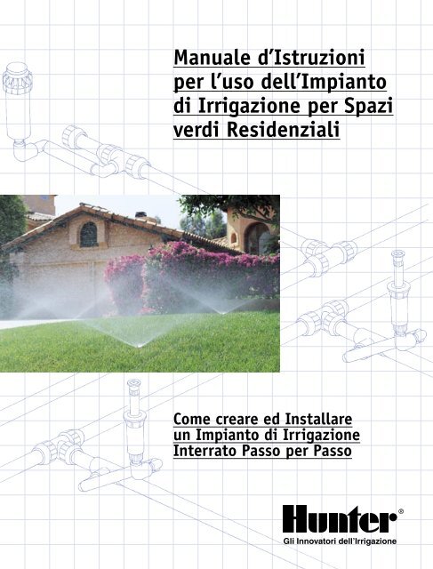
Manuale d'Istruzioni per l'uso dell'Impianto di Irrigazione ... - Irrigarden
Manuale d'Istruzioni per l'uso dell'Impianto di Irrigazione ... - Irrigarden
Manuale d'Istruzioni per l'uso dell'Impianto di Irrigazione ... - Irrigarden

You also want an ePaper? Increase the reach of your titles
YUMPU automatically turns print PDFs into web optimized ePapers that Google loves.
<strong>Manuale</strong> d’Istruzioni<br />
<strong>per</strong> l’uso dell’Impianto<br />
<strong>di</strong> <strong>Irrigazione</strong> <strong>per</strong> Spazi<br />
ver<strong>di</strong> Residenziali<br />
Come creare ed Installare<br />
un Impianto <strong>di</strong> <strong>Irrigazione</strong><br />
Interrato Passo <strong>per</strong> Passo<br />
®<br />
Gli Innovatori dell’<strong>Irrigazione</strong>
Questo manuale vuole essere uno strumento <strong>di</strong> ausilio<br />
<strong>per</strong> semplificare la progettazione e l’installazione <strong>di</strong><br />
piccoli sistemi <strong>di</strong> irrigazione <strong>per</strong> aree residenziali.<br />
Si presenta in un formato pratico e <strong>di</strong> gradevole consultazione<br />
g razie alle illustrazioni ed agli schemi che ne facilitano<br />
l’uso.<br />
Si consiglia <strong>di</strong> scorrere il presente manuale <strong>per</strong> prendere<br />
<strong>di</strong>mestichezza con le tecniche <strong>di</strong> installazione sia se si esegue<br />
l’installazione <strong>di</strong> un impianto <strong>di</strong> irrigazione <strong>per</strong> la prima volta<br />
che se si ha già es<strong>per</strong>ienza.<br />
Per agevolare la fase <strong>di</strong> progettazione dell’impianto si troverà<br />
in allegato un foglio <strong>di</strong> carta millimetrata. Inoltre il manuale<br />
presenta <strong>di</strong>verse configurazioni <strong>di</strong> irrigatori, sistemi <strong>di</strong> valvole,<br />
tubazioni e meto<strong>di</strong> <strong>per</strong> collegare la conduttura principale <strong>di</strong><br />
innaffiamento al circuito idraulico domestico. Nel manuale sono<br />
altresì forniti alcuni utili consigli <strong>per</strong> il proprio impianto, un<br />
glossario dei termini utilizzati e delle tabelle in ultima pagina che<br />
in<strong>di</strong>cano caratteristiche e prestazioni degli irrigatori Hunter.<br />
Per il calcolo delle portate (l/min), delle pressioni <strong>di</strong> esercizio<br />
e delle <strong>di</strong>mensioni delle tubazioni ci si è basati su una <strong>per</strong><strong>di</strong>ta <strong>di</strong><br />
carico ragionevole ed una velocità dell’acqua compatibile con<br />
un sistema <strong>di</strong> irrigazione destinato ad aree residenziali. Per ogni<br />
eventuale informazione sulla progettazione e l’installazione del<br />
sistema <strong>di</strong> irrigazione rivolgersi al riven<strong>di</strong>tore locale Hunter.<br />
Per impianti <strong>di</strong> gran<strong>di</strong> <strong>di</strong>mensioni Hunter raccomanda <strong>di</strong><br />
affidare l’esecuzione dei lavori a dei professionisti del settore.<br />
Questi installatori potranno re<strong>per</strong>ire ogni ulteriore informazione<br />
presso il <strong>di</strong>stributore locale Hunter.<br />
Sommario<br />
Misurare il Terreno e Disegnare una<br />
Pianta del Proprio Giar<strong>di</strong>no .............................1<br />
Calcolare la Capacità Nominale del<br />
Proprio Sistema <strong>di</strong> <strong>Irrigazione</strong> .........................2<br />
Sezione della Canalizzazione <strong>di</strong> Alimentazione<br />
Capacità Nominale del Sistema <strong>di</strong> <strong>Irrigazione</strong><br />
La Scelta degli Irrigatori ....................................... 3<br />
Determinare la Posizione degli Irrigatori ................ 4<br />
Determinare la Quantità <strong>di</strong> Gruppi<br />
<strong>di</strong> Irrigatori da Installare ...................................... 5<br />
Esempio <strong>di</strong> Capacità <strong>per</strong> Zona<br />
Determinare la Posizione delle Valvole<br />
e la Sezione delle Canalizzazioni............................ 6<br />
Sezione Tubi<br />
Determinare il Punto <strong>di</strong> Raccordo........................... 7<br />
Schema Generale dell’Impianto<br />
<strong>di</strong> <strong>Irrigazione</strong>................................................... 8–9<br />
Installazione dell’Impianto ............................10–12<br />
Realizzazione del Punto <strong>di</strong> Raccordo<br />
Installazione della Canalizzazione Principale<br />
Installazione delle Valvole Elettriche<br />
Installazione delle Canalizzazioni Laterali<br />
Installazione del Programmatore<br />
Installazione degli Irrigatori<br />
Riempimento delle Trincee<br />
Lista del Materiale da Acquistare ....................13–15<br />
Glossario dei Termini Utilizzati............................ 16<br />
Guida all’<strong>Irrigazione</strong><br />
............................ Co<strong>per</strong>tina, Ultima Pagina, Interno<br />
Tabelle delle Caratteristiche degli<br />
Irrigatori Hunter ................Co<strong>per</strong>tina, Ultima Pagina<br />
®<br />
Gli Innovatori dell’<strong>Irrigazione</strong><br />
U.S.A.: 1940 Diamond Street • San Marcos, California 92069, U.S.A.<br />
Australia: 8 The Parade West • Kent Town, South Australia 5067<br />
Europe: Bât. A2 - Europarc de Pichaury • 1330, rue Guillibert de la Lauzières<br />
13856 Aix-en-Provence Cedex 3, France • (33) 4-42-37-16-90 • FAX: (33) 4-42-39-89-71<br />
Internet: www.HunterIndustries.com
1<br />
Misurare il Terreno e Disegnare<br />
una Pianta del Proprio Giar<strong>di</strong>no<br />
A. Disegnate la Pianta del Vostro Giar<strong>di</strong>no<br />
1. Misurare il terreno e tracciare la posizione della casa su <strong>di</strong><br />
esso. Su un foglio a parte <strong>di</strong>segnare la pianta del giar<strong>di</strong>no e<br />
riportare le quote misurate.<br />
ZONA B<br />
ZONA C<br />
ZONA D<br />
Zone sulla<br />
Pianta<br />
ZONA A<br />
ZONA E<br />
Non <strong>di</strong>menticare <strong>di</strong> in<strong>di</strong>care tutti i sentieri pavimentati, le<br />
terrazze, le vie carrozzabili e le recinzioni. In<strong>di</strong>care anche gli<br />
alberi, le aree a coltura, le roccaglie e le zone a prato.<br />
2. Disegnare poi la pianta del giar<strong>di</strong>no sulla carta millimetrata<br />
fornita in scala 1:100, 1:200 o secondo la scala più adatta.<br />
Annotare la scala prescelta. In<strong>di</strong>care le parti seminate a prato,<br />
a fiori e gli arbusti, le zone a co<strong>per</strong>tura vegetale e i gran<strong>di</strong><br />
alberi.<br />
3. Dividere la pianta del terreno in zone rettangolari o quadrate<br />
(le più gran<strong>di</strong> possibile) <strong>per</strong> delimitare le zone anteriori,<br />
posteriori, laterali, a prato, alberate o con altre piante ed<br />
identificarle con lettere <strong>di</strong>verse (A, B, C, D, ecc., vedere<br />
esempio nello schema in alto).<br />
Permesso<br />
(secondo la normativa in vigore)<br />
Nastro isolante<br />
Seghetto<br />
Isolante<br />
Sega <strong>per</strong> metalli<br />
Martello<br />
Chiavi <strong>per</strong> tubi<br />
Teli in plastica<br />
Pinze<br />
Stracci<br />
Rastrello<br />
Cacciavite<br />
Ban<strong>di</strong>erine<br />
Pala<br />
Spray <strong>di</strong> pittura <strong>per</strong> segnalazione<br />
Metro<br />
Scavatrice<br />
Pinze <strong>per</strong> tagliare cavo elettrico<br />
CONSIGLI PRATICI<br />
Attrezzi e materiale necessario<br />
Bomboletta <strong>per</strong> marcatura<br />
Cesoie metalliche<br />
Valvola automatica <strong>di</strong> drenaggio<br />
(da usare nei paesi fred<strong>di</strong> <strong>per</strong><br />
evitare la formazione <strong>di</strong> ghiaccio<br />
nelle tubazioni)<br />
Graffe metalliche isolate<br />
Pluviometro<br />
Valvole <strong>di</strong> arresto<br />
Nastro in teflon (usato <strong>per</strong> tutti<br />
i raccor<strong>di</strong> filettati in PVC o in<br />
polietilene)<br />
Pozzetti da 150 o 250 mm<br />
Per i tubi in polietilene:<br />
Presa a staffa<br />
Poly Pipe<br />
Se Usa tubi in PVC:<br />
Colla<br />
Solvente<br />
Pinze <strong>per</strong> taliare PVC
2<br />
Calcolare la Capacità Nominale<br />
del Proprio Sistema <strong>di</strong> <strong>Irrigazione</strong><br />
B. Calcolare la Capacità Nominale del Proprio<br />
Sistema <strong>di</strong> <strong>Irrigazione</strong><br />
Per avere un sistema <strong>di</strong> irrigazione efficiente è necessario<br />
anzitutto calcolare la sua capacità nominale, ovvero la quantità<br />
d’acqua <strong>di</strong> cui può <strong>di</strong>sporre. Se si usa acqua <strong>di</strong> città seguire la<br />
procedura descritta <strong>di</strong> seguito. Se invece l’acqua viene prelevata<br />
da un fiume, lago un pozzo, o un serbatoio rivolgersi al proprio<br />
riven<strong>di</strong>tore Hunter o all’installatore della pompa <strong>per</strong> conoscere le<br />
caratteristiche <strong>di</strong> pressione e portata. In questo caso, inserire le<br />
caratteristiche <strong>di</strong> pressione e portata della pompa nelle<br />
caselle “capacita nominale” e “pressione <strong>di</strong> utilizzazione” in<br />
fondo alla pagina.<br />
1. Pressione dell’Acqua (Bar)<br />
Per conoscere la pressione dell’acqua collegare un manometro<br />
ad una presa, il più vicino possibile al contatore. Verificare<br />
che non sia in funzione nessun apparecchio che consumi acqua.<br />
Aprire il rubinetto e annotare il valore visualizzato: questo è il<br />
valore <strong>di</strong> pressione statica (in bar).<br />
2. Portata (l/min)<br />
Per determinare la portata <strong>di</strong>sponibile <strong>per</strong> il sistema è<br />
necessario esaminare due fattori:<br />
A. Qual è la capacità del contatore installato o la sezione<br />
del circuito <strong>di</strong> alimentazione in acqua ?<br />
La capacità dei contatori è normalmente in<strong>di</strong>cata sul corpo<br />
del contatore. I modelli più comuni <strong>di</strong> contatori sono da<br />
15 mm, 20 mm e 25 mm.<br />
B. Qual è la sezione della canalizzazione <strong>di</strong> mandata<br />
dell’acqua ?<br />
Misurare il <strong>di</strong>ametro esterno della canalizzazione che collega<br />
la rete idrica municipale alla casa. In mancanza <strong>di</strong> strumenti<br />
idonei misurare con una cor<strong>di</strong>cella lo sviluppo della circonferenza<br />
riportarsi alla tabella qui a fianco <strong>per</strong> risalire alla sezione.<br />
3. Capacità Nominale del Sistema<br />
Facendo riferimento alla tabella Capacità nominale del<br />
sistema riportata qui a fianco determinare la capacità nominale<br />
del sistema in litri al minuto (l/min) secondo le tre cifre che<br />
sono state appena rilevate. Trascrivere queste cifre nella casella<br />
l/min, poi spostarsi sulla pressione statica del sistema e scendere<br />
lungo la colonna <strong>per</strong> trovare la pressione <strong>di</strong> esercizio del sistema.<br />
Trascrivere la pressione nella casella bar in quanto si tratta della<br />
pressione <strong>di</strong> utilizzazione che servirà a scegliere gli elementi <strong>di</strong><br />
irrigazione e a progettare l’impianto.<br />
Abbiamo appena calcolato la portata massima d’acqua in<br />
l/min e la pressione approssimativa <strong>di</strong> esercizio <strong>di</strong>sponibili <strong>per</strong> il<br />
sistema. Se tali valori massimi vengono oltrepassati l’irrigazione<br />
non sarà adeguata ed eventuali colpi <strong>di</strong> ariete potrebbero danneggiare<br />
gravemente l’impianto <strong>di</strong> irrigazione. Questi due valori sono<br />
insomma estremamente importanti nella fase <strong>di</strong> progettazione<br />
dell’impianto.<br />
Per verificare la pressione<br />
dell’acqua fissare un<br />
manometro ad una presa,<br />
il più vicino possibile al<br />
contatore. Il manometro<br />
può essere acquistato<br />
presso il proprio riven<strong>di</strong>tore<br />
locale Hunter.<br />
Annotare qui la pressione statica: _______________________<br />
Annotare qui il modello del<br />
contatore d’acqua <strong>di</strong> cui si <strong>di</strong>spone:______________________<br />
Trascrivere qui la sezione della<br />
canalizzazione <strong>di</strong> alimentazione in acqua: ________________<br />
SEZIONE DELLA CANALIZZAZIONE DI ALIMENTAZIONE<br />
LUNGHEZZA APPROSS.<br />
DELLA CORDICELLA<br />
Sezione canalizzazione in<br />
rame<br />
Sezione canalizzazione in<br />
ferro zincato<br />
Sezione della canalizzazione<br />
in polietilene<br />
Le canalizzazioni sono calcolate sulla base <strong>di</strong> 30 metri <strong>di</strong> tubazione in PVC a parete spessa. Per le tubazioni<br />
in rame togliere 7,6 l/min e <strong>per</strong> la nuova serie <strong>di</strong> tubi zincati togliere 19 l/min.<br />
La pressione <strong>di</strong> utilizzazione è la pressione approssimativa <strong>di</strong>sponibile al livello dell’irrigatore e deve essere<br />
usata solo a titolo in<strong>di</strong>cativo <strong>per</strong> la scelta degli elementi <strong>di</strong> irrigazione e <strong>per</strong> la progettazione dell’impianto.<br />
I valori della tabella della Capacità nominale sono calcolati in base alle portate e velocità comunemente<br />
accettate. In alcuni casi ed esclusivamente sulle tubazioni in rame gli installatori aumentano questa velocità<br />
da 2,3 m/sec a 2,7 m/sec. Se, in caso <strong>di</strong> tubazioni in rame, non vengono dedotti i 7,6 l/min la velocità è <strong>di</strong><br />
circa 2,75 m/sec. A questa velocità le <strong>per</strong><strong>di</strong>te dovute all’attrito vengono ad essere sostanzialmente aumentate,<br />
il che avrà un’incidenza sulla pressione <strong>di</strong> esercizio. Per poter trarre vantaggio dalla tabella, la lunghezza delle<br />
canalizzazioni in rame non deve in alcun caso su<strong>per</strong>are 15 metri qualora non si vogliano dedurre i 7,6 l/min.<br />
l/min Bars kPa<br />
7 cm 8.25 cm 9 cm 10.5 cm 11 cm 13.5 cm<br />
20 mm 25 mm 32 mm<br />
20 mm 25 mm 32 mm<br />
20 mm 25 mm 32 mm<br />
CAPACITÀ NOMINALE DEL SISTEMA DI IRRIGAZIONE<br />
PRESSIONE<br />
STATICA<br />
Contatore<br />
D’acqua<br />
15 mm<br />
20 mm<br />
25 mm<br />
Bars<br />
kPa<br />
ALIM.<br />
in acqua<br />
13 mm<br />
20 mm<br />
25 mm<br />
20 mm<br />
25 mm<br />
32 mm<br />
20 mm<br />
25 mm<br />
32 mm<br />
PRESSIONE DI<br />
UTILIZZAZIONE<br />
2<br />
200<br />
MAX<br />
l/min<br />
7.6<br />
15<br />
15<br />
15<br />
19<br />
19<br />
15<br />
19<br />
19<br />
2.8<br />
275<br />
MAX<br />
l/min<br />
15<br />
23<br />
26<br />
23<br />
26<br />
45<br />
26<br />
30<br />
53<br />
3.5<br />
350<br />
MAX<br />
l/min<br />
19<br />
30<br />
30<br />
30<br />
38<br />
64<br />
30<br />
53<br />
91<br />
4<br />
415<br />
MAX<br />
l/min<br />
23<br />
30<br />
38<br />
34<br />
53<br />
76<br />
34<br />
68<br />
98<br />
4.8<br />
480<br />
MAX<br />
l/min<br />
26<br />
38<br />
49<br />
38<br />
64<br />
83<br />
45<br />
76<br />
114<br />
5.5<br />
550<br />
MAX<br />
l/min<br />
26<br />
45<br />
57<br />
45<br />
76<br />
83<br />
45<br />
76<br />
130<br />
Bar 1,7 2 2,4 3 3,5 3,8<br />
kPa<br />
175 200 240 310 345 380<br />
Capacità Nominale<br />
Utilizzazione
3<br />
La Scelta Degli Irrigatori<br />
C. La Scelta Degli Irrigatori<br />
Per gli impianti residenziali esistono due tipi <strong>di</strong> irrigatori:<br />
le turbine <strong>per</strong> le gran<strong>di</strong> su<strong>per</strong>fici e gli irrigatori statici <strong>per</strong> le<br />
su<strong>per</strong>fici più piccole. In nessun caso turbine ed irrigatori statici<br />
devono essere installati nella stessa zona.<br />
ZONA B<br />
ZONA C<br />
ZONA D<br />
Installazione<br />
Degli Irrigatori<br />
ZONA A<br />
ZONA E<br />
1. Le turbine <strong>per</strong> le gran<strong>di</strong> su<strong>per</strong>fici coprono 8 x 8 metri e più.<br />
2. Gli irrigatori statici vengono usati normalmente <strong>per</strong> irrigare<br />
su<strong>per</strong>fici più piccole.<br />
Per ambedue i tipi esistono irrigatori con alzo installati al<br />
livello del suolo e irrigatori fissi montati su supporto ed installati<br />
sopra al suolo.<br />
La su<strong>per</strong>ficie <strong>di</strong> 8 x 8 metri è fornita solo a titolo in<strong>di</strong>cativo e<br />
non è quin<strong>di</strong> vincolante. L’unico criterio da prendere in considerazione<br />
è quello economico sapendo che l’installazione <strong>di</strong><br />
una turbina al posto <strong>di</strong> un irrigatore statico consente <strong>di</strong> ridurre la<br />
lunghezza della canalizzazione e la quantità <strong>di</strong> valvole e richiede<br />
la posa <strong>di</strong> un programmatore più piccolo.<br />
Irrigatori Statici SRS o PS.<br />
Pro-Spray® <strong>per</strong> Spazi Ver<strong>di</strong> <strong>di</strong><br />
Piccole Dimensioni<br />
Spaziatura da 3 a 5 metri<br />
Irrigatore PGM <strong>per</strong> Spazi Ver<strong>di</strong><br />
<strong>di</strong> Dimensioni Interme<strong>di</strong>e<br />
Spaziatura da 5 a 8 metri<br />
ESEMPIO<br />
Capacità Nominale del Sistema<br />
Contatore d’Acqua 15 mm<br />
Sezione della Canalizzazione 25 mm<br />
Pressione Statica 4,8 Bar, 480 kPa<br />
In Funzione <strong>di</strong> Questa Capacità Nominale<br />
49 l/min 3,5 Bar, 345 kPa<br />
Turbina PGP® <strong>per</strong> Spazi Ver<strong>di</strong> <strong>di</strong><br />
Gran<strong>di</strong> Dimensioni<br />
Spaziatura da 8 a 12 metri<br />
I-20 Ultra <strong>per</strong> Spazi Ver<strong>di</strong> <strong>di</strong><br />
Gran<strong>di</strong> Dimensioni<br />
Spaziatura da 8 a 12 metri<br />
Capacità Nominale<br />
Pressione <strong>di</strong> Utilizzazione
4<br />
Determinare la Posizione Degli Irrigatori<br />
D. Disegnare la Posizione Degli Irrigatori<br />
Determinare dove posizionare nel giar<strong>di</strong>no le turbine a grande<br />
arco <strong>di</strong> irrigazione e gli irrigatori che coprono una zona più<br />
piccola. Per le turbine è opportuno prevedere una <strong>di</strong>stanza <strong>di</strong><br />
8–12 metri tra ciascun elemento e <strong>per</strong> gli irrigatori statici 3–5<br />
metri. In questo modo si otterrà una leggera sovrapposizione<br />
dell’innaffiamento che consentirà una co<strong>per</strong>tura uniforme. Non<br />
<strong>di</strong>sporre nella stessa zona i due tipi <strong>di</strong> irrigatore.<br />
Non <strong>di</strong>stanziare troppo tra loro gli irrigatori; rispettare le<br />
specifiche in<strong>di</strong>cate nelle tabelle delle caratteristiche riportate<br />
nell’ultima pagina del manuale. La <strong>di</strong>stanza tra gli elementi<br />
è funzione della su<strong>per</strong>ficie co<strong>per</strong>ta da ciascun irrigatore.<br />
L’innaffiamento deve raggiungere tanto l’irrigatore contiguo che<br />
quello opposto. Lavorare <strong>per</strong> zona e cominciare ad installare gli<br />
irrigatori:<br />
Fase 1. Gli angoli del giar<strong>di</strong>no sono i punti più delicati. Con un<br />
compasso <strong>di</strong>segnare in ogni angolo un arco <strong>di</strong> circonferenza che<br />
rappresenta l’irrigatore quarto <strong>di</strong> giro.<br />
Fase 2. Se la portata degli irrigatori quarto <strong>di</strong> giro non è sufficiente<br />
da <strong>per</strong>mettere la sovrapposizione, prevedere altri irrigatori<br />
lungo il <strong>per</strong>imetro del giar<strong>di</strong>no. Disegnare i loro archi <strong>di</strong> irrigazione.<br />
Fase 3. Verificare che gli irrigatori <strong>per</strong>iferici raggiungano gli<br />
irrigatori a loro opposti. In caso contrario aggiungere nel mezzo<br />
degli irrigatori a 360°. Per semplificare l’installazione tracciare<br />
delle linee <strong>per</strong>pen<strong>di</strong>colari che collegano gli irrigatori <strong>per</strong>iferici<br />
tra loro. Poi con il compasso tracciare un cerchio a partire da un<br />
irrigatore <strong>per</strong>iferico <strong>per</strong> assicurarsi che tutta la zona sia co<strong>per</strong>ta.<br />
Fase 1<br />
Cominciare ad installare gli irrigatori<br />
negli angoli in quanto sono la parte<br />
più <strong>di</strong>fficile del giar<strong>di</strong>no.<br />
Fase 2<br />
Se necessario aggiungere degli<br />
irrigatori sui lati.<br />
Fase 3<br />
Gli spazi <strong>di</strong> gran<strong>di</strong> <strong>di</strong>mensioni possono richiedere l’installazione aggiuntiva<br />
<strong>di</strong> irrigatori <strong>per</strong>iferici o <strong>di</strong> irrigatori centrali <strong>per</strong> garantire la co<strong>per</strong>tura testa<br />
a testa o <strong>per</strong> sovrapposizione.<br />
Zone curve<br />
Ri<strong>di</strong>segnare le zone curve con una serie <strong>di</strong> linee rette. Posizionare gli<br />
irrigatori come se si trattasse <strong>di</strong> zone rettangolari o quadrate. L’uso <strong>di</strong> ugelli<br />
ad arco regolabile si adatta <strong>per</strong>fettamente a questo tipo <strong>di</strong> configurazione.<br />
Scelta Degli Ugelli<br />
Quando si crea il proprio impianto <strong>di</strong> irrigazione è importante verificare che la<br />
pluviometria (tasso <strong>di</strong> precipitazione dell’acqua) sia uniforme su ciascuna zona<br />
<strong>di</strong> co<strong>per</strong>tura. Si ottiene una “precipitazione adeguata” scegliendo gli ugelli adatti<br />
o posizionando nello stesso circuito irrigatori con lo stesso grado <strong>di</strong> pluviometria.<br />
I due criteri da prendere in considerazione sono: la portata dell’irrigatore<br />
e l’arco <strong>di</strong> irrigazione. Il <strong>di</strong>segno <strong>di</strong> destra mostra tre <strong>di</strong>versi tipi <strong>di</strong> irrigatori con<br />
tassi <strong>di</strong> precipitazione adeguati. In tutti i casi ogni quarto <strong>di</strong> cerchio riceve 5<br />
litri/minuto (m/min). La precipitazione si può quin<strong>di</strong> <strong>di</strong>re adeguata.<br />
90° = 5 l/min<br />
90° = 5 l/min<br />
180° = 10 l/min<br />
180° =<br />
360° = 20 l/min<br />
10 l/min<br />
360° = 20 l/min<br />
Esempio: se si decide <strong>di</strong> usare degli PGP e si<br />
sono <strong>di</strong>sposti nello stesso circuito irrigatori da<br />
un quarto <strong>di</strong> cerchio, mezzo cerchio e cerchio<br />
intero, si potranno usare gli ugelli #3, #8 e<br />
#10 oppure gli ugelli #5, #8 e #10 a seconda<br />
della portata <strong>di</strong>sponibile
5<br />
Determinare la Quantità <strong>di</strong> Gruppi<br />
<strong>di</strong> Irrigatori da Installare<br />
E. Determinare il Numero <strong>di</strong> Circuiti <strong>di</strong> <strong>Irrigazione</strong><br />
da Installare<br />
A meno che il giar<strong>di</strong>no non sia <strong>di</strong> <strong>di</strong>mensioni estremamente<br />
ridotte, non si <strong>di</strong>sporrà quasi certamente <strong>di</strong> una portata d’acqua<br />
sufficiente <strong>per</strong> innaffiarlo tutto contemporaneamente. Peraltro<br />
alcune parti del giar<strong>di</strong>no richiedono una quantità d’acqua<br />
su<strong>per</strong>iore a quella <strong>di</strong>sponibile al rubinetto (capacità nominale).<br />
ZONA B<br />
ZONA C<br />
ZONA D<br />
In<strong>di</strong>care i Circuiti<br />
<strong>di</strong> <strong>Irrigazione</strong><br />
ZONA A<br />
ZONA E<br />
Il giar<strong>di</strong>no deve essere <strong>di</strong>viso in circuiti. Iniziare con la zona A:<br />
1. Riportarsi alla pressione <strong>di</strong> utilizzazione in<strong>di</strong>cata a pag. 2 che<br />
servirà <strong>per</strong> determinare la <strong>di</strong>stanza tra gli irrigatori e la portata<br />
necessaria secondo la tabella delle caratteristiche.<br />
2. Trascrivere la portata <strong>di</strong> ciascun irrigatore della zona<br />
nell’apposito spazio (vedere tabella all’ultima pagina<br />
del manuale).<br />
3. Sommare i valori e <strong>di</strong>viderli <strong>per</strong> la portata totale d’acqua<br />
<strong>di</strong>sponibile <strong>per</strong> avere il numero <strong>di</strong> circuiti necessari alla zona.<br />
4. Se il numero totale <strong>di</strong> circuiti non è un numero intero,<br />
arrotondarlo <strong>per</strong> eccesso (1, 2 <strong>di</strong>venta 2). In questo modo si<br />
avrà il numero totale <strong>di</strong> valvole necessarie <strong>per</strong> gli irrigatori<br />
della zona.<br />
5. Disponendo ora del numero esatto <strong>di</strong> circuiti del proprio<br />
giar<strong>di</strong>no, <strong>di</strong>videre il numero <strong>di</strong> irrigatori in modo da avere<br />
approssimativamente la stessa portata d’acqua in ogni circuito.<br />
Non prevedere troppi irrigatori nella stessa zona. Tenersi<br />
entro i limiti compatibili con la capacità nominale del<br />
proprio impianto.<br />
6. Disegnare ed identificare le valvole <strong>di</strong> ogni zona<br />
(Zona 1, Zona 2, ecc.).<br />
7. Ripetere le o<strong>per</strong>azioni D e E <strong>per</strong> tutte le zone.<br />
Portata totale <strong>di</strong><br />
tutti gli irrigatori <strong>di</strong><br />
una stessa zona<br />
Zona<br />
÷ =<br />
Capacità nominale in<br />
l/min (pag. 2)<br />
ESEMPIO DI CAPACITÀ PER ZONA<br />
l/min<br />
Per Zona<br />
÷<br />
Capacità<br />
Nominale<br />
Numero <strong>di</strong> circuiti<br />
nella zona<br />
=<br />
Arrotondare<br />
<strong>per</strong> Eccesso<br />
N. <strong>di</strong> Circuiti<br />
A 32 ÷ 49 = 1<br />
B 51 ÷ 49 = 1<br />
C 69 ÷ 49 = 2<br />
D 62 ÷ 49 = 2<br />
E 39 ÷ 49 = 1<br />
ZONA C = 68,7 L/MIN<br />
IRRIGATORI PGM PER<br />
SPAZI DI DIMENSIONI<br />
INTERMEDIE
6<br />
Determinare la Posizione delle Valvole<br />
e la Sezione delle Canalizzazioni<br />
F. Determinare la Posizione delle Valvole e delle<br />
Canalizzazioni e le Rispettive Sezioni<br />
Ogni circuito deve avere la sua valvola che <strong>per</strong>mette <strong>di</strong><br />
alimentare o <strong>di</strong> escludere l’alimentazione ad un circuito <strong>di</strong><br />
irrigazione. Prevedere una valvola <strong>per</strong> ogni circuito e poi<br />
raggrupparle in blocco.<br />
ZONA B<br />
CIRCUITO 2<br />
ZONA C<br />
CIRCUITO 3<br />
CIRCUITO 4<br />
CIRCUITO 5<br />
CIRCUITO 6<br />
ZONA D<br />
Valvole e<br />
Canalizzazioni<br />
ZONA A<br />
CIRCUITO 1 CIRCUITO 7<br />
ZONA E<br />
Determinare il luogo dove si desidera posizionare il blocco<br />
<strong>di</strong> <strong>di</strong>stribuzione <strong>di</strong> ciascun circuito: nella parte anteriore del<br />
giar<strong>di</strong>no, sul retro oppure in più punti. Il blocco <strong>di</strong> <strong>di</strong>stribuzione<br />
può essere situato ovunque, tuttavia si consiglia <strong>di</strong> installarlo in<br />
un punto facilmente accessibile <strong>per</strong> la manutenzione. Situare il<br />
blocco <strong>di</strong> <strong>di</strong>stribuzione vicino alla zona servita dalle valvole ma<br />
in un punto in cui non si venga bagnati se si deve mettere in<br />
funzione l’impianto manualmente.<br />
ZONA A – CIRCUITO 1<br />
ZONA B – CIRCUITO 2<br />
ZONA C – CIRCUITO 3<br />
ZONA C – CIRCUITO 4<br />
ZONA D – CIRCUITO 5<br />
ZONA D – CIRCUITO 6<br />
ZONA E – CIRCUITO 7<br />
Punto <strong>di</strong> raccordo<br />
Canalizzazione Laterale<br />
I due tipi <strong>di</strong> canalizzazione usati più frequentemente negli<br />
impianti <strong>di</strong> irrigazione sono le canalizzazioni in PVC o in polietilene.<br />
Verificare presso il proprio riven<strong>di</strong>tore locale Hunter il tipo<br />
più utilizzato nella propria zona.<br />
1. Collegare con una riga tutti gli irrigatori <strong>di</strong> ogni circuito, come<br />
mostrato in figura. Scegliere il tragitto più <strong>di</strong>retto, con il minor<br />
numero possibile <strong>di</strong> curve o <strong>di</strong> cambiamenti <strong>di</strong> <strong>di</strong>rezione.<br />
2. Collegare la canalizzazione alla valvola del circuito (nel modo<br />
più <strong>di</strong>retto possibile).<br />
3. Determinare quin<strong>di</strong> la sezione delle canalizzazioni cominciando<br />
dall’irrigatore più lontano del circuito. La canalizzazione<br />
che collega il penultimo irrigatore all’ultimo deve avere<br />
una sezione <strong>di</strong> 20 mm (vedere tabella delle sezioni delle<br />
canalizzazioni).<br />
Sezione Tubi<br />
Raccordo degli Irrigatori con Canalizzazioni in Polietilene<br />
OR<br />
SEZIONE TUBI<br />
Portata Max <strong>per</strong> i Tubi <strong>di</strong> <strong>Irrigazione</strong><br />
PVC <strong>di</strong> Parete<br />
Grossa<br />
PVC <strong>di</strong> Parete<br />
Fine<br />
OR<br />
Tubo <strong>di</strong><br />
Polietilene<br />
20 mm 34 l/min 38 l/min 30 l/min<br />
25 mm 57 l/min 60 l/min 50 l/min<br />
32 mm 91 l/min 99 l/min 83 l/min<br />
GIUSTO<br />
SBAGLIATO
7<br />
Determinare il Punto <strong>di</strong> Raccordo<br />
4. Fare la somma delle portate degli ultimi due irrigatori <strong>per</strong><br />
determinare la sezione della canalizzazione successiva.<br />
5. Al totale così ottenuto aggiungere la portata richiesta <strong>per</strong><br />
l’irrigatore successivo.<br />
6. Continuare fino a raggiungere la valvola <strong>di</strong> circuito. Fare attenzione<br />
a non usare una canalizzazione con una sezione inferiore<br />
ai valori in<strong>di</strong>cati in tabella.<br />
7. Ripetere le o<strong>per</strong>azioni da 1 a 7 <strong>per</strong> ogni rete.<br />
Canalizzazione principale<br />
1. Determinare la posizione del punto <strong>di</strong> raccordo (P.D.R.) che<br />
deve trovarsi relativamente vicino al contatore.<br />
2. Collegare tutti i <strong>di</strong>stributori con una riga, poi collegare la riga<br />
al punto <strong>di</strong> raccordo.<br />
3. La canalizzazione principale deve avere una sezione maggiore<br />
<strong>di</strong> quella della canalizzazione secondaria più grande.<br />
Regioni Tem<strong>per</strong>ate: Raccordo a T a compressione in ottone <strong>per</strong><br />
collegare l’impianto <strong>di</strong> irrigazione all’alimentazione in acqua<br />
della casa.<br />
G. Punto <strong>di</strong> Raccordo<br />
Raccordo alla rete Idrica Urbana<br />
Usare un raccordo a compressione a Tee <strong>per</strong> collegare<br />
l’impianto <strong>di</strong> irrigazione all’arrivo dell’acqua. Il raccordo può<br />
anche essere fatto su una canalizzazione in rame, in PVC o in ferro<br />
zincato senza necessità <strong>di</strong> saldature né <strong>di</strong> filettature.<br />
In alcuni casi è opportuno prevedere una valvola <strong>di</strong> non<br />
ritorno <strong>per</strong> proteggere il circuito dell’acqua potabile. Installare<br />
eventualmente una canalizzazione in rame tra il punto <strong>di</strong> raccordo<br />
e la valvola <strong>di</strong> non ritorno. Non <strong>di</strong>menticare <strong>di</strong> verificare i regolamenti<br />
locali e <strong>di</strong> richiedere alle autorità preposte le particolari<br />
con<strong>di</strong>zioni applicabili.<br />
Climi Fred<strong>di</strong><br />
Se l’impianto risiede in una regione molto fredda ed il punto<br />
<strong>di</strong> raccordo si trova nel seminterrato installare il drenaggio subito<br />
dopo valvola a sfera <strong>per</strong> consentire in inverno <strong>di</strong> scaricare l’acqua<br />
tra il punto <strong>di</strong> raccordo e il gruppo <strong>di</strong> valvole.<br />
Regioni Molto Fredde: Se il punto <strong>di</strong> raccordo si trova nel<br />
seminterrato, prevedere un punto <strong>di</strong> drenaggio subito a<br />
valle della valvola a sfera che serve ad isolare l’impianto <strong>di</strong><br />
inaffiamento prima dell’arrivo del grande freddo.<br />
Punto Finale<br />
L’impianto <strong>di</strong> irrigazione è finalmente progettato. Verificare <strong>di</strong><br />
aver previsto irrigatori <strong>per</strong> tutte le zone del giar<strong>di</strong>no e verificare<br />
anche la sezione delle canalizzazioni.<br />
CONSIGLIO<br />
Molti installatori professionisti raccomanadano<br />
l' uso <strong>di</strong> tubi <strong>di</strong> PVC <strong>per</strong> ottenere una<br />
pressione costante lungo la linea dalla valvola<br />
<strong>di</strong> non ritorno sino alle valvole <strong>per</strong> il controllo<br />
delle zone. Alcune zone, comunque, richiedono l'<br />
uso <strong>di</strong> bronzo. Consultate le normative in vigore<br />
prima <strong>di</strong> installare il vostro sistema.<br />
Installazione della pompa al punto <strong>di</strong> prelievo.
PROGRAMMATORE PER IRRIGAZIONE<br />
AUTOMATICA SERIE SRC O EC O PRO-C ®<br />
CAVI A BASSA TENSIONE DEL<br />
PROGRAMMATORE<br />
POZZETTO QUADRATO O<br />
CIRCOLARE<br />
RACCORDI STAGNI<br />
VAVOLA ELETTRICA SERIE SRV O PGV<br />
RACCORDI MASCHIO<br />
COLLETTORE SMONTABILE TEE, GOMITO<br />
VALVOLA DI ARRESTO<br />
PUNTO DI RACCORDO
IRRIGATORE PGP ®<br />
PRESA A STAFFA<br />
Ø 25 X O Ø 32 X 3⁄4"<br />
GIUNTO SNODATO 3⁄4" X 30 CM<br />
T A COMPRESSIONE Ø 25 X O Ø 32<br />
TUBO IN POLIETILENE<br />
RACCORDO A T DI RIDUZIONE IN POLIETILENE<br />
RACCORDO A T A COMPRESSIONE Ø 25 O<br />
Ø 32 CON DERIVAZIONE FILETTATA DA 1⁄2"<br />
IRRIGATORI STATICI<br />
PS O SRS<br />
RACCORDO A COMPRESSIONE MASCHIO Ø 25 X O Ø 32 X 1"<br />
GIUNTO SNODATO 1⁄2" X 30 CM<br />
Schema Generale<br />
<strong>dell'Impianto</strong> <strong>di</strong> <strong>Irrigazione</strong><br />
®<br />
Gli Innovatori nell'<strong>Irrigazione</strong>
10<br />
Installazione dell’Impianto<br />
H. Come Realizzare il Proprio Impianto<br />
Realizzazione del Raccordo alla Rete Idrica Urbana<br />
1. Riferirsi allo schema generale dell’impianto <strong>di</strong> irrigazione<br />
(pagg. 8–9).<br />
2. Interrom<strong>per</strong>e l’alimentazione in acqua della casa.<br />
3. Praticare un’a<strong>per</strong>tura <strong>per</strong> rendere visibile la canalizzazione<br />
<strong>di</strong> alimentazione.<br />
4. Su questa canalizzazione tagliare via un pezzo <strong>di</strong> 25 mm<br />
<strong>per</strong> adattarvi un raccordo a compressione, poi avvitare i<br />
da<strong>di</strong> <strong>di</strong> compressione.<br />
5. Montare il raccordo e la valvola <strong>di</strong> isolamento.<br />
6. Installare un pozzetto <strong>per</strong> poter accedere alla valvola.<br />
7. Aprire <strong>di</strong> nuovo l’alimentazione in acqua della casa.<br />
Installazione della Canalizzazione Principale<br />
1. Servendosi <strong>di</strong> una bomboletta <strong>di</strong> vernice marcare le canalizzazioni<br />
che collegano il punto <strong>di</strong> raccordo ai vari punti del<br />
blocco <strong>di</strong> <strong>di</strong>stribuzione.<br />
2. Se si lavora su un prato già piantato stendere un telo <strong>di</strong><br />
plastica a circa 60 cm dal punto in cui si scaverà la trincea.<br />
3. Con una pala piatta tagliare delle strisce <strong>di</strong> prato larghe circa<br />
30 cm e profonde 4–5 cm. Arrotolare le strisce <strong>di</strong> prato e<br />
posarle con la terra sul telo in plastica.<br />
4. Esecuzione delle trincee: verificare le norme locali in vigore<br />
relative alla profon<strong>di</strong>tà <strong>di</strong> posa delle canalizzazioni <strong>per</strong> gli<br />
impianti <strong>di</strong> irrigazione. In assenza <strong>di</strong> vincoli particolari scavare<br />
a mano o con l’apposito attrezzo, che si può eventualmente<br />
noleggiare, una trincea profonda 25–30 cm.<br />
5. Posa della canalizzazione sotto pavimentazioni o sentieri<br />
pavimentati. Metodo della martellatura: prendere un tubo<br />
zincato ed ostruirne le due estremità, poi servendosi <strong>di</strong><br />
un martello farlo passare sotto la pavimentazione<br />
(vedere illustrazione).<br />
6. Montare una valvola <strong>di</strong> non ritorno conformemente alle norme<br />
in vigore (opzionale secondo il paese).<br />
7. Installazione della canalizzazione: <strong>di</strong>sporre i tubi ed i raccor<strong>di</strong><br />
vicino alle trincee, a seconda dell’impianto previsto.<br />
Fare attenzione a non far entrare terra nei tubi.<br />
8. A partire dal punto <strong>di</strong> raccordo (o eventualmente dalla valvola<br />
<strong>di</strong> non ritorno) misurare la lunghezza necessaria <strong>per</strong> il tubo;<br />
tagliare e farla arrivare fino all’ultimo <strong>di</strong>stributore o irrigatore<br />
(vedere pagg. 8 e 9).<br />
9. Per interrare la canalizzazione principale riportarsi alle<br />
istruzioni fornite a pagina 12.<br />
Prima <strong>di</strong> eseguire la trincea marcare il tracciato dell’impianto <strong>di</strong><br />
innaffiamento utilizzando delle ban<strong>di</strong>erine ed una bomboletta<br />
<strong>di</strong> vernice.<br />
Posizionare anzitutto un telo <strong>di</strong> plastica <strong>per</strong> deporvi il prato<br />
arrotolato e poi scavare una trincea profonda 25-30 cm <strong>per</strong><br />
la canalizzazione principale e 15-25 cm <strong>per</strong> le canalizzazioni<br />
secondarie.<br />
Per il passaggio sotto una pavimentazione usare un martello <strong>per</strong><br />
far passare un tubo zincato chiuso alle due estremità.
11<br />
Installazione dell’Impianto<br />
Installazione del Blocco Valvole e delle Valvole Elettriche<br />
1. Riferirsi al dettaglio corrispondente sullo schema generale.<br />
2. Prevedere una <strong>di</strong>stanza minima <strong>di</strong> 15 cm tra le valvole <strong>per</strong><br />
facilitarne la manutenzione.<br />
3. Pre<strong>di</strong>sporre un tratto <strong>di</strong> tubo aggiuntivo (minimo <strong>di</strong> 8 cm)<br />
tappato <strong>per</strong> ulteriori ampliazioni.<br />
4. Installare i pozzetti come in<strong>di</strong>cato a pagina 12.<br />
Installazione delle Canalizzazioni Secondarie<br />
Se non si <strong>di</strong>spone <strong>di</strong> più <strong>di</strong> un giorno o due da de<strong>di</strong>care<br />
all’installazione dell’impianto e questo si trova in una zona già<br />
strutturata paesaggisticamente, preparare tutti i circuiti ed installarli<br />
in una sola volta come segue:<br />
Montaggio dei Raccor<strong>di</strong> a Compressione<br />
A. Unendo PVC:<br />
1. Mettere della colla sia dentro<br />
l'unione che fuori dal tubo.<br />
2. Inserire il tubo nell'unione e<br />
pulire l' eccesso <strong>di</strong> colla.<br />
1. Organizzazione dell’impianto: servendosi del <strong>di</strong>segno e<br />
delle ban<strong>di</strong>erine <strong>di</strong> segnalazione, marcare la posizione degli<br />
irrigatori e delle valvole <strong>di</strong> circuito. Regolare in modo da<br />
ottenere una co<strong>per</strong>tura completa. Se si deve mo<strong>di</strong>ficare il<br />
progetto (<strong>per</strong> esempio aggiungendo un irrigatore) ricalcolare<br />
le portate <strong>per</strong> verificare <strong>di</strong> rientrare comunque nei limiti della<br />
capacità nominale dell’impianto (pagina 5) e verificare con<br />
la tabella della sezione dei tubi che la mo<strong>di</strong>fica non abbia<br />
conseguenze sulla sezione scelta (pagina 6).<br />
2. Con la bomboletta <strong>di</strong> vernice marcare il tracciato delle<br />
tubazioni secondarie.<br />
3. Scavo delle trincee: in assenza <strong>di</strong> particolari prescrizioni<br />
scavare delle trincee profonde 20–60 cm.<br />
4. Posa dei tubi: posizionare i tubi ed i raccor<strong>di</strong> lungo la trincea,<br />
seguendo l’or<strong>di</strong>ne <strong>di</strong> installazione. Fare attenzione a non far<br />
entrare terra nei tubi.<br />
5. Per interrare i tubi secondari riportarsi a pagina 12.<br />
B. Tubo <strong>di</strong> Polietilene:<br />
1. Mettere l'anello su tubo<br />
e poi inserire il raccordo<br />
a pressione.<br />
C. Unendo tubi in Polietilene<br />
con raccor<strong>di</strong> a pressione<br />
1. Inserire l‘estremitá del tubo<br />
nel raccordo ed avvitare il<br />
dado <strong>di</strong> compressione.<br />
Tubo <strong>di</strong> Polietilene:<br />
2. Stringere l'anello attorno al<br />
tubo e al raccordo.<br />
2. Spingere il tubo <strong>per</strong> far<br />
passare la guarnizione.<br />
Inserire l‘estremitá del tubo<br />
nel raccordo ed avvitare il<br />
dado <strong>di</strong> compressione.<br />
Posa delle valvole automatiche <strong>di</strong> drenaggio nelle regioni fredde:<br />
posizionare le valvole nel punto basso <strong>di</strong> ogni circuito.<br />
Disporre i tubi e gli irrigatori lungo le trincee, in corrispondenza<br />
del punto in cui verranno installati.
12<br />
Installazione dell’Impianto<br />
Installazione del Programmatore<br />
1. Decidere dove si desidera installare il programmatore.<br />
La maggior parte dei programmatori ad uso residenziale<br />
vengono installati all’interno (<strong>per</strong> esempio in garage).<br />
Attenersi alle istruzioni fornite con il programmatore.<br />
E’ necessaria un’alimentazione a 220V.<br />
2. Usare cavi con co<strong>di</strong>ce <strong>di</strong> colore <strong>per</strong> raccordare le valvole al<br />
programmatore. E’ necessario un cavo <strong>per</strong> ogni valvola più un<br />
cavo comune <strong>per</strong> tutte le valvole. Se l’impianto comprende<br />
5 circuiti, prevedere 6 cavi abbastanza lunghi <strong>per</strong> collegare il<br />
programmatore alla valvola più lontana.<br />
3. Verifica della co<strong>per</strong>tura: collegate il programmatore<br />
all’alimentazione (230V): Testate le stazioni del programmatore<br />
una <strong>per</strong> una <strong>per</strong> verifcare i raccor<strong>di</strong> gli irrigatori,<br />
mo<strong>di</strong>ficate gli ugelli se necessario al fine <strong>di</strong> otienere una<br />
buona co<strong>per</strong>tura.<br />
4. Raccordare il cavo alle valvole con raccor<strong>di</strong> stagni.<br />
Prevedere un cavo <strong>per</strong> ogni valvola più un cavo comune<br />
che sarà collegato ad uno dei capi <strong>di</strong> ogni valvola.<br />
Installazione degli Irrigatori<br />
1. Installare tutti gli irrigatori <strong>di</strong> una rete, salvo l’ultimo. Lasciare<br />
l’ultimo o gli ultimi irrigatori smontati <strong>per</strong> una pulizia corretta.<br />
2. Messa in acqua dell’impianto: mettere in acqua ruotando<br />
manualmente la valvola; in questo modo verranno eliminate<br />
le impurità presenti nel tubo. Questa o<strong>per</strong>azione deve essere<br />
eseguita anche se si è certi che durante l’installazione non<br />
sia entrato nulla all’interno dei tubi. Non appena l’acqua<br />
inizia a fuoriuscire pulita, chiudere il rubinetto ed installare i<br />
rimanenti irrigatori.<br />
3. Verifica della co<strong>per</strong>tura: raccordare il circuito al<br />
programmatore <strong>per</strong> verificare che i cavi ed i raccor<strong>di</strong> elettrici<br />
funzionino correttamente. Regolare gli irrigatori e verificare<br />
che la co<strong>per</strong>tura <strong>di</strong> irrigazione sia corretta.<br />
Riempimento delle Trincee<br />
1. Non interrare le valvole. Prevedere un pozzetto <strong>per</strong> facilitarne<br />
l’accesso. Installare il pozzetto al momento <strong>di</strong> richiudere le<br />
trincee.<br />
2. Togliere tutti i sassi che si trovano sotto il tubo. Ricoprire<br />
3⁄4 o 1⁄2 della trincea <strong>per</strong> volta e compattare bene la terra man<br />
mano che si avanza. Quando si installano i pozzetti e gli<br />
irrigatori accertarsi <strong>di</strong> trovarsi a filo del suolo.<br />
Usare dei cavi colorati <strong>per</strong> collegare le valvole al programmatore.<br />
Prevedere un cavo <strong>per</strong> ogni valvola più un cavo comune a tutte.<br />
CONSIGLIO<br />
Quando si calcola il numero <strong>di</strong> cavi<br />
necessari all’impianto, prevedere sempre<br />
due cavi extra <strong>per</strong> eventuali future<br />
estensioni. E’ sicuramente più facile<br />
installarli adesso che più tar<strong>di</strong>, quando<br />
tutta la vegetazione sarà nuovamente<br />
rigogliosa.<br />
EQUIVALENZA UNITÀ<br />
USA E METRICHE<br />
1⁄2" = 15/21<br />
3⁄4" = 20/27<br />
1" = 26/34<br />
11⁄4" = 33/42
13<br />
Lista del Materiale da Acquistare<br />
Per determinare il materiale da acquistare servirsi del <strong>di</strong>segno<br />
e dell’elenco sotto in<strong>di</strong>cato. Se si hanno dei dubbi sul nome <strong>di</strong> un<br />
pezzo riferirsi al <strong>di</strong>segno generale. Usando delle matite colorate<br />
contare o misurare il materiale necessario sul <strong>di</strong>segno e riportare<br />
la quantità ottenuta nella lista in basso. Fare attenzione a non<br />
<strong>di</strong>menticare nulla!<br />
1. Punto <strong>di</strong> Raccordo Esterno – Climi Tem<strong>per</strong>ati<br />
CONTATORE<br />
POZZETTO (QUADRATO/TONDO)<br />
1. Punto <strong>di</strong> raccordo: stabilire la lista dei pezzi necessari <strong>per</strong><br />
sezione. Verificare <strong>di</strong> attenersi alle norme locali sulle valvole <strong>di</strong><br />
non ritorno applicabili e annotare le attrezzature necessarie.<br />
VALVOLA A<br />
RUBINETTO<br />
2. Tubi: misurare le lunghezze <strong>di</strong> tubo necessarie e le sezioni<br />
richieste. Prevedere sempre un margine in lunghezza.<br />
Contare il numero <strong>di</strong> raccor<strong>di</strong> necessari <strong>per</strong> la canalizzazione<br />
principale e quelle secondarie, annotando tipo e sezione.<br />
PUNTO DI RACCORDO<br />
ADATTATORE<br />
MASCHIO<br />
1. PUNTO DI RACCORDO<br />
Lista dei pezzi necessari <strong>per</strong> il punto <strong>di</strong> raccordo<br />
Tee a Compressione (compressione x<br />
compressione x avvitamento)<br />
Valvola a rubinetto o a sfera in ottone.<br />
Pozzetto <strong>per</strong> valvole<br />
2. Punto <strong>di</strong> Raccordo Interno – Climi Fred<strong>di</strong><br />
VALVOLA DI<br />
SCARICO<br />
PUNTO DI RACCORDO<br />
VALVOLA A<br />
RUBINETTO<br />
O A SFERA<br />
IN OTTONE<br />
Valvola <strong>di</strong> non ritorno<br />
Manometro<br />
TEE A COMPRESSIONE<br />
CONTATORE<br />
2. TUBI E RACCORDI (Calcolare la lunghezza del tubo e la quantità <strong>di</strong> raccor<strong>di</strong> necessari)<br />
PVC (liscio x liscio x liscio) 20 mm 25 mm 32 mm Polietilene (a compressione o con unioni a incastro)<br />
TUBO PVC<br />
METRI NECESSARI<br />
PRINCIPALE PRINCIPALE TUBO IN POLIETILENA<br />
SECONDARIO<br />
SECONDARIO METRI NECESSARI<br />
TEE S x S x S i x i x i TEE<br />
S x S x 13 mm (1⁄2")T<br />
i x i x 13 mm (1⁄2")T<br />
S x S x 20 mm (3⁄4")T<br />
i x i x 20 mm (3⁄4")T<br />
GOMITO<br />
90° S x S 90° i x i GOMITO<br />
90° S x 20 mm (3⁄4")T 90° i x 20 mm (3⁄4")T<br />
90˚<br />
45˚<br />
90° S x 25 mm (1")T 90° i x 25 mm (1")T<br />
45° S x S 45° i x i<br />
RIDUTTORE 25 mm S x 20 mm (3⁄4")S 25 mm (1")i x 20 mm (3⁄4")i RIDUTTORE<br />
32 mm S x 25 mm (1")S 32 mm (11⁄4")i x 25 mm (1")i<br />
TEE DI<br />
RIDUZIONE<br />
S x S x S<br />
i x i x i<br />
TEE DI<br />
DIDUZIONE<br />
ADATTATORE<br />
MASCHIO S x T i x T<br />
ADATTATORE<br />
MASCHIO<br />
RIDUTTORE<br />
S x S<br />
i x i<br />
RIDUTTORE<br />
S = Raccordo Liscio T = Raccordo Filettato Maschio o Femmina i = Raccor<strong>di</strong> a Compressione
14<br />
Lista del Materiale da Acquistare<br />
3. Elettrovalvole: contare il numero <strong>di</strong> elettrovalvole <strong>per</strong> sezione.<br />
Annotare i pezzi necessari nella lista dettagliata.<br />
4. Programmatore: il modello <strong>di</strong> programmatore <strong>di</strong>penderà dal<br />
numero <strong>di</strong> valvole. Misurare la lunghezza del cavo che collega<br />
il programmatore alla valvola più lontana.<br />
Nota: usare un cavo multifilo a bassa tensione con co<strong>di</strong>ce<br />
<strong>di</strong> colore. Prevedere un cavo <strong>per</strong> ogni valvola più un cavo<br />
comune che verrà collegato a tutte le valvole. Esempio: se<br />
secondo il <strong>di</strong>segno sono necessari 20 cm <strong>di</strong> cavo elettrico e la<br />
scala del <strong>di</strong>segno è <strong>di</strong> 1:100 (1 cm = 1 m) saranno necessari<br />
200 metri <strong>di</strong> cavo (20 x 100 = 200). Non <strong>di</strong>menticare <strong>di</strong><br />
prevedere del cavo extra <strong>per</strong> facilitare il lavoro all’altezza dei<br />
raccor<strong>di</strong> e <strong>per</strong> stendere agevolmente il cavo lungo il muro fino<br />
al programmatore.<br />
3. Valvole<br />
VALVOLA ELETTRICA<br />
SERIE SRV<br />
POZZETTO<br />
RACCORDI STAGNI<br />
3. ELETTROVALVOLE<br />
Lista dei pezzi necessari <strong>per</strong> creare dei blocchi <strong>di</strong> <strong>di</strong>stribuzione<br />
Valvola SRV o PGV Hunter<br />
Pozzetto<br />
Raccor<strong>di</strong> maschi<br />
Dimensione<br />
1" (25 mm)<br />
Quantita<br />
4. Programmatore<br />
RACCORDI MASCHIO<br />
PROGRAMMATORE SERIE SRC<br />
Raccor<strong>di</strong> stagni<br />
Programmatore SRC o EC Hunter<br />
(1 mm <strong>di</strong>ametro). Cavo elettrico <strong>di</strong><br />
connessione.<br />
4. PROGRAMMATORI<br />
________ Stazioni<br />
________ Metri<br />
CAVO BASSA<br />
TENSIONE DEL<br />
PROGRAMMATORE<br />
CONSIGLIO<br />
Non lasciar cadere mai i tubi <strong>di</strong> PVC.<br />
Se cadono e colpiscono una roccia o<br />
cemento, i tubi si potrebbero scheggiare<br />
e lanciare piccoli pezzi taglienti <strong>per</strong> aria.<br />
Anche se i tubi non si rompono potrebbero<br />
creparsi e, posteriormente, cedere<br />
sotto la pressione dell'acqua. Questo<br />
puÚ accadere se durante il trasporto si<br />
lascia che i tubi si scontrino fra <strong>di</strong> loro.<br />
GUAINA PVC PER<br />
CAVO BASSA TENSIONE<br />
(OPZIONALE)
15<br />
Lista del Materiale da Acquistare<br />
5. Irrigatori: contare il numero <strong>di</strong> irrigatori necessari <strong>per</strong> tipo<br />
e annotarne la quantità sulla tabella.<br />
6. Giunti Snodati: contare il numero <strong>di</strong> irrigatori e determinare<br />
il numero <strong>di</strong> giunti snodati premontati Hunter che sono<br />
necessari, oppure.<br />
7. Calcolare il numero <strong>di</strong> raccor<strong>di</strong> necessari <strong>per</strong> ciascuna<br />
sezione.<br />
5. Irrigatori<br />
PGP<br />
6. Giunto Snodato<br />
USARE UN RACCORDO ARTICOLATO<br />
HUNTER PREASSEMBLATO SERIE SJ<br />
GIUNTO SNODATO HUNTER<br />
5. IRRIGATORI<br />
Contare sul vostro <strong>di</strong>segno il numero totale <strong>di</strong> irrigatori e riportario qui sotto :<br />
TURBINE CON ALZO E FISSE<br />
CON ALZO, PRATO<br />
Raccordo PGM 13mm (1⁄2")<br />
Raccordo PGP ® 20mm (3⁄4")<br />
Raccordo I-20 Ultra 20mm (3⁄4")<br />
GIUNTI SNODATI HUNTER PREMONTATI<br />
Raccordo PGM 13mm (1⁄2")<br />
Raccordo PGP ® 20mm (3⁄4")<br />
Raccordo I-20 Ultra 20mm (3⁄4")<br />
Quantità<br />
IRRIGATORI CON UGELLI AD ARCO REGOLABILE<br />
CON ALZO, PRATO<br />
Raccordo SRS o Pro-Spray ®<br />
13mm (1⁄2")<br />
Raccordo PS 13mm (1⁄2")<br />
GIUNTI SNODATI HUNTER PREMONTATI<br />
Raccordo SRS o Pro-Spray ®<br />
13mm (1⁄2")<br />
Raccordo PS 13mm (1⁄2")<br />
Quantità<br />
IRRIGATORE<br />
STATICO DELLA<br />
SERIE SRS O<br />
PRO-SPRAY O PS<br />
UGELLI AD ARCO REGOLABILE<br />
6. Giunto Snodato<br />
USARE UN RACCORDO ARTICOLATO<br />
HUNTER PREASSEMBLATO SERIE SJ<br />
RACCORDO A T DI RIDUZIONE<br />
O PRESA A STAFFA<br />
TUBO IN PVC O<br />
POLIETILENE<br />
6. GIUNTI SNODATI HUNTER PREMONTATI<br />
SERIES SJ<br />
Quantità<br />
SJ-506 1⁄2" x 15 cm<br />
SJ-512 1⁄2" x 30 cm<br />
SJ-7512 1⁄2" x 3⁄4" x 30 cm<br />
SJ-712 3⁄4" x 30 cm<br />
IRRIGATORI<br />
STATICI SERIE<br />
SRS O PS<br />
GIUNTO SNODATO HUNTER<br />
7. GIUNTI SNODATI<br />
Riporti il numero <strong>di</strong> irrigatori necessari nel punto 5 nella tabella sottostante <strong>per</strong><br />
poter determinare il numero <strong>di</strong> parti <strong>di</strong> cui si ha bisogno:<br />
1⁄2" Diametro dell'irrigatore<br />
1⁄2" Raccordo ad arco maschio-femmina x 3 =<br />
1⁄2" x 8" sch 80 raccordo flessibile in polietilene x 1 =<br />
1⁄2" x 14" (or ___") raccordo x 1 =<br />
3⁄4" Diametro dell'irrigatore<br />
3⁄4" Raccordo ad arco maschio-femmina x 3 =<br />
3⁄4" x 8" raccordo flessibile in polietilene x 1 =<br />
3⁄4" x 14" (or ___") raccordo x 1 =<br />
Total<br />
Total<br />
ALTRO MONTAGGIO:<br />
PROLUNGA MODULABILE<br />
O SU MISURA<br />
PRESA A STAFFA<br />
ALTRO MONTAGGIO: PROLUNGA<br />
MODULABILE O SU MISURA<br />
TUBO IN POLIETILENE
16<br />
Glossario dei Termini Utilizzati<br />
ARCO DI IRRIGAZIONE – Definisce l’ampiezza angolare della zona<br />
co<strong>per</strong>ta da un irrigatore. Un irrigatore il cui arco <strong>di</strong> irrigazione è <strong>di</strong> 90°<br />
coprirà un quarto <strong>di</strong> cerchio.<br />
BLOCCO VALVOLE – Gruppo <strong>di</strong> valvole.<br />
CAVO ELETTRICO – In un impianto <strong>di</strong> irrigazione automatica si usa del<br />
cavo a bassa tensione interrato che collega le valvole elettriche al<br />
programmatore. Il cavo normalmente utilizzato negli impianti <strong>di</strong> innaffiamento<br />
privati è un cavo multifilo inguainato con identificazione <strong>per</strong> colore.<br />
CIRCUITO – Insieme <strong>di</strong> irrigatori comandati da un singola valvola.<br />
COLPO D'ARIETE – L'aumento della pressione che sorge quando si<br />
chiude <strong>di</strong> colpo una valvola. In alcuni casi la pressione puÚ causare che i<br />
tubi vibrino e facciano rumore. Il colpo d'ariete Ë provocato normalmente<br />
da valvoole <strong>di</strong> chiusura rapida o da tubi troppo stretti che provocano un<br />
flusso d'acqua ad alta velocita.<br />
DRENAGGIO PUNTO BASSO – Acqua che rimane nelle tubazioni<br />
dopo l’interruzione <strong>di</strong> una valvola e che viene evacuata lentamente<br />
dall’irrigatore posizionato più in basso. Il drenaggio può essere evitato<br />
installando una valvola antidrenaggio.<br />
GITTATA – Lunghezza del getto dell’irrigatore. Con un ugello che ha una<br />
gittata <strong>di</strong> 5,2 metri la lunghezza del getto ottenuta sarà <strong>di</strong> 5,2 metri.<br />
IRRIGATORI STATICI O FISSI – Irrigatori che <strong>di</strong>ffondono un getto piatto<br />
costituito da goccioline d’acqua. Questi irrigatori hanno una portata<br />
massima <strong>di</strong> 5,2 metri e fanno parte della categoria degli irrigatori <strong>per</strong><br />
“piccole su<strong>per</strong>fici.”<br />
L/MIN – LITRI AL MINUTO – E’ in<strong>di</strong>spensabile conoscere la portata in litri<br />
al minuto <strong>per</strong> determinare il tipo <strong>di</strong> irrigatore da installare. Ogni irrigatore<br />
ha una portata specifica. La portata totale <strong>di</strong> tutti gli irrigatori in uno<br />
stesso circuito non può essere su<strong>per</strong>iore alla portata d’acqua <strong>di</strong>sponibile.<br />
PERDITA DI CARICO – L’acqua che circola in un contatore, una valvola,<br />
una tubazione o un raccordo trova una resistenza o un attrito notevoli.<br />
Quando la velocità del flusso aumenta, aumenta anche la <strong>per</strong><strong>di</strong>ta <strong>per</strong><br />
attrito. L’attrito riduce la pressione statica <strong>di</strong>sponibile.<br />
PRESSIONE – Si misura con un manometro e si esprime in bar o in kPa.<br />
La pressione statica è il valore misurato quando non c’è flusso d’acqua<br />
e tutti i circuiti sono chiusi. La pressione <strong>di</strong>namica è il valore misurato<br />
quando il sistema è a<strong>per</strong>to e l’acqua circola.<br />
PORTATA – Espressa in litri al minuto (l/min) o in metri cubi <strong>per</strong> ora (m 3 /h),<br />
la portata corrisponde alla misura del volume d’acqua in circolazione in<br />
una tubazione o in un irrigatore in un dato <strong>per</strong>iodo <strong>di</strong> tempo.<br />
PRINCIPALE (TUBAZIONE PRINCIPALE) – Tubazione sotto pressione<br />
che collega il punto <strong>di</strong> raccordo alle elettrovalvole <strong>di</strong> un circuito.<br />
PROGRAMMA – Un programma è l’insieme <strong>di</strong> dati che l’utilizzatore<br />
inserisce nella memoria del programmatore e che determineranno i tempi<br />
<strong>di</strong> irrigazione dell’impianto. Il programmatore <strong>di</strong> un impianto <strong>di</strong> irrigazione<br />
automatica deve ricevere tre informazioni: i giorni <strong>di</strong> irrigazione, l’ora <strong>di</strong><br />
inizio dell’irrigazione <strong>di</strong> ogni zona ed i tempi <strong>di</strong> irrigazione <strong>di</strong> ogni zona.<br />
PROGRAMMATORE – Chiamato anche timer, fa parte <strong>di</strong> un impianto <strong>di</strong><br />
irrigazione automatica e determina in quale momento deve entrare in<br />
funzione una valvola e <strong>per</strong> quanto tempo. Il timer invia un segnale a<br />
bassa tensione alla valvola che va ad aprirsi <strong>per</strong> un <strong>per</strong>iodo <strong>di</strong> tempo<br />
predeterminato, <strong>per</strong>mettendo l’alimentazione degli irrigatori. La scelta<br />
del modello <strong>di</strong> programmatore deve essere fatta in funzione del numero<br />
<strong>di</strong> circuiti che comprende l’impianto <strong>di</strong> irrigazione.<br />
PUNTO DI RACCORDO – Punto in cui si collega la canalizzazione<br />
principale dell’irrigatore.<br />
SECONDARIA (TUBAZIONE SECONDARIA) – Tubazione non in<br />
pressione <strong>per</strong>manente che collega la valvola agli irrigatori.<br />
STAZIONE – Termine usato <strong>per</strong> la programmazione. Gli irrigatori <strong>di</strong> un<br />
circuito <strong>di</strong> irrigazione sono collegati me<strong>di</strong>ante un tubo ad una valvola<br />
che è cablata su una stazione del programmatore. Un programmatore a<br />
6 stazioni può gestire da 1 a 6 valvole.<br />
TASSO DI PRECIPITAZIONE – Viene in<strong>di</strong>cato in mm / hora. Il tasso <strong>di</strong><br />
precipitazione è il tasso con cui viene <strong>di</strong>stribuita l'acqua. Il tasso <strong>di</strong><br />
precipitazione deve essere uguale <strong>per</strong> tutti gli irrigatori <strong>di</strong> una zona e<br />
così erogare la stessa quantità d'acqua. Diversi modelli <strong>di</strong> irrigatori non<br />
dovrebbero essere installati in una stessa zona. Irrigatori <strong>di</strong> corta e larga<br />
gittata possono usare gli stessi LPM, ma siccome le aree che coprono<br />
sono <strong>di</strong>verse, i mm <strong>per</strong> hora applicati sono <strong>di</strong>versi.<br />
TESTA A TESTA – Questa espressione descrive la corretta posizione degli<br />
irrigatori statici e delle turbine. Ogni irrigatore deve essere posizionato<br />
in modo tale da raggiungere un altro irrigatore (o il 50% del <strong>di</strong>ametro<br />
regolato) <strong>per</strong> garantire la completa co<strong>per</strong>tura delle aree ed evitare <strong>di</strong><br />
lasciare spazi non innaffiati.<br />
TIMER – Ve<strong>di</strong> Programmatore.<br />
TRINCEA – Le trincee <strong>per</strong> le canalizzazioni secondarie devono avere una<br />
profon<strong>di</strong>tà <strong>di</strong> 15-20 cm. In generale lo scavo dei primi 10 centimetri non<br />
richiede particolari precauzioni. Ma dai 15 centimetri in poi è tassativo<br />
procedere con cautela, sapendo che nel giar<strong>di</strong>no sono interrate delle<br />
canalizzazioni. Per questa ragione <strong>di</strong>sponendo i tubi a 15 o 20 cm si<br />
eviterà il rischio <strong>di</strong> rom<strong>per</strong>li quando si eseguono i lavori stagionali come il<br />
<strong>di</strong>ssodamento e la piantagione <strong>di</strong> piante a fioritura annuale. La canalizzazione<br />
principale viene installata in linea <strong>di</strong> principio prima <strong>di</strong> quelle<br />
secondarie e deve essere interrata più in profon<strong>di</strong>tà <strong>per</strong> consentire la<br />
posa delle canalizzazioni secondarie alla profon<strong>di</strong>tà necessaria. E’ inoltre<br />
opportuno far correre i cavi a bassa tensione nella stessa trincea, sotto la<br />
canalizzazione principale, in modo da proteggerli.<br />
TUBO DI POLIETILENE – Il polietilene è nero, è un tubo flessibile e molto<br />
ado<strong>per</strong>ato nelle zone in cui ci sono problemi <strong>di</strong> gelo durante l'inverno.<br />
Sui tubi in Polietilene si usano raccor<strong>di</strong> a compressione.<br />
TUBO IN PVC – Il tubo più usato nelle aree <strong>di</strong> clima caldo. Normalmente<br />
colorati, i tubi <strong>di</strong> PVC sono più rigi<strong>di</strong> <strong>di</strong> quelli in Polietilene, e hanno<br />
bisogno <strong>di</strong> colla <strong>per</strong> i raccor<strong>di</strong>.<br />
TURBINE – Irrigatori a turbina che emanano un getto d’acqua ruotando<br />
lentamente <strong>per</strong> eseguire un’irrigazione a cerchio con <strong>di</strong>ametri che<br />
possono variare dai 5 metri fino ai 23 metri e più. Le turbine vengono<br />
classificate nella categoria degli irrigatori “<strong>per</strong> gran<strong>di</strong> su<strong>per</strong>fici”.<br />
VALVOLA – In un impianto <strong>di</strong> irrigazione esistono vari tipi <strong>di</strong> valvole ma<br />
comunque classificate in due categorie: le valvole <strong>di</strong> irrigazione e le<br />
valvole <strong>di</strong> arresto. Nell’ambito <strong>di</strong> queste due categorie esistono numerosi<br />
modelli. In un impianto <strong>di</strong> irrigazione il termine “valvola” designa in<br />
generale una valvola elettrica.<br />
VALVOLA DI NON RITORNO – Dispositivo montato tra il punto <strong>di</strong> raccordo<br />
e gli irrigatori, che consente <strong>di</strong> evitare il riflusso dell’acqua sporca nel<br />
circuito dell’acqua potabile. Il tipo <strong>di</strong> valvola <strong>di</strong> non ritorno varia a seconda<br />
dei paesi. L’utilizzatore dovrà verificare presso il proprio riven<strong>di</strong>tore<br />
Hunter o presso il competente ente locale quale sia il tipo <strong>di</strong> valvola <strong>di</strong><br />
non ritorno omologata <strong>per</strong> la specifica area <strong>di</strong> installazione.<br />
VALVOLA DI NON RITORNO – Dispositivo che consente all’acqua <strong>di</strong><br />
scorrere in un’unica <strong>di</strong>rezione. Tutte le valvole <strong>di</strong> non ritorno sono munite<br />
<strong>di</strong> una molla che tiene la valvola in posizione chiusa, impedendo in tal<br />
modo all’irrigatore <strong>di</strong> erogare acqua fintanto che nel circuito non venga<br />
raggiunta una pressione predefinita. La molla trattiene l’acqua in<br />
una tubazione che si trovi ad un <strong>di</strong>slivello <strong>di</strong> 2-3 metri; si adatta quin<strong>di</strong><br />
<strong>per</strong>fettamente agli impianti installati in pendenza.<br />
VALVOLA DI REGOLAZIONE DI CIRCUITO<br />
Le VALVOLE MANUALI non vengono più utilizzate così frequentemente<br />
come in passato. L’impianto <strong>di</strong> irrigazione a comando manuale evita <strong>di</strong><br />
dover spostare irrigatori da una zona all’altra ma l’utilizzatore <strong>per</strong>de il<br />
vantaggio del sistema automatico.<br />
Le VALVOLE ELETTRICHE si usano con i programmatori. Rappresentano<br />
una soluzione facile ed economica <strong>per</strong> irrigare prati, roccaglie e giar<strong>di</strong>ni.<br />
Con un sistema automatico non ci saranno più problemi <strong>di</strong> spreco<br />
d’acqua anche se l’utilizzatore <strong>di</strong>mentica <strong>di</strong> spegnere l’impianto.<br />
Le valvole elettriche consentono <strong>di</strong> erogare esclusivamente la quantità<br />
d’acqua richiesta da ogni circuito.<br />
VOLUME – Si esprime in litri o in metri cubi e si usa <strong>per</strong> fornire la quantità<br />
d’acqua <strong>di</strong>sponibile o la quantità d’acqua utilizzata (ve<strong>di</strong> portata).
17<br />
Guida all’<strong>Irrigazione</strong><br />
In<strong>di</strong>viduare le Proprie Esigenze<br />
La portata d’acqua necessaria varia in funzione della<br />
vegetazione da innaffiare, delle caratteristiche del terreno e<br />
del clima. I prati <strong>di</strong> recente semina devono essere tenuti costantemente<br />
umi<strong>di</strong> e le zone decorative piantate in stagione richiedono<br />
un’irrigazione quoti<strong>di</strong>ana o almeno ogni due giorni. Attenersi ai<br />
consigli forniti nei paragrafi che seguono.<br />
Consigli <strong>di</strong> irrigazione<br />
1. Non far funzionare mai più <strong>di</strong> una valvola <strong>per</strong> volta.<br />
2. Irrigare la notte quando la pressione è ideale ed il vento<br />
scarso. L’irrigazione mattutina limita anche il fenomeno<br />
dell’evaporazione. Irrigando durante le calde giornate estive si<br />
rischia <strong>di</strong> bruciare le piante.<br />
3. Nella maggior parte delle regioni il prato deve ricevere<br />
40-50 mm d’acqua alla settimana durante la stagione più calda.<br />
Tale quantità d’acqua deve essere leggermente aumentata<br />
nelle regioni estremamente calde e aride.<br />
4. Eseguire un test manuale del proprio impianto ogni settimana<br />
oppure verificare che tutto funzioni correttamente. Controllare<br />
e pulire gli irrigatori <strong>per</strong> ottimizzare l’irrigazione.<br />
Regioni molto fredde<br />
Se l’impianto viene installato in una regione ove l’inverno è<br />
molto rigido, prima dell’arrivo del gelo sarà opportuno escludere<br />
il programmatore, chiudere la valvola <strong>di</strong> arresto dell’irrigatore<br />
principale, svuotare tutto il circuito dall’acqua residua e far<br />
asciugare le canalizzazioni. Se non si ha <strong>di</strong>mestichezza con le<br />
procedure <strong>per</strong> svuotare completamente l’impianto contattare il<br />
riven<strong>di</strong>tore locale della Hunter che potrà fornire le istruzioni<br />
necessarie oppure l’in<strong>di</strong>rizzo <strong>di</strong> un professionista che possa<br />
eseguire il lavoro.<br />
GUIDA ALL’IRRIGAZIONE<br />
Climi fred<strong>di</strong> e non ari<strong>di</strong> : prevedere 25 mm d’acqua alla settimana.<br />
Climi cal<strong>di</strong> e ari<strong>di</strong> : prevedere 50 mm d’acqua alla settimana.<br />
Terreni argillosi, particelle fini, velocità<br />
<strong>di</strong> assorbimento lenta.<br />
Terra vegetale, particelle <strong>di</strong> me<strong>di</strong>e<br />
<strong>di</strong>mensioni, velocità <strong>di</strong> assorbimento<br />
me<strong>di</strong>a.<br />
Terreni sabbiosi, gran<strong>di</strong> particelle,<br />
velocità <strong>di</strong> assorbimento relativamente<br />
veloce.<br />
Q.tà d’acqua<br />
da prevedere/<br />
settimana<br />
Programmare tempi <strong>di</strong> irrigazione<br />
più brevi, aumentare il numero <strong>di</strong><br />
cicli <strong>di</strong> irrigazione al giorno e ridurre<br />
il numero <strong>di</strong> giorni <strong>di</strong> irrigazione alla<br />
settimana.<br />
Programmare tempi <strong>di</strong> irrigazione più<br />
lunghi e ridurre il numero <strong>di</strong> cicli <strong>di</strong><br />
irrigazione alla settimana.<br />
Programmare dei tempi <strong>di</strong> irrigazione<br />
più brevi, aumentare il numero dei cicli<br />
<strong>di</strong> irrigazione al giorno e aumentare<br />
il numero <strong>di</strong> giorni <strong>di</strong> irrigazione alla<br />
settimana.<br />
PROGRAMMAZIONE DEI TEMPI DI<br />
IRRIGAZIONE SU 7 GIORNI<br />
Irrigatori<br />
Statici<br />
Irrigatori<br />
PGM<br />
Irrigatore<br />
PGP ®<br />
I-20 Ultra<br />
Irrigatore<br />
25 mm 40 min. 130 min. 150 min. 150 min.<br />
50 mm 80 min. 260 min. 300 min. 300 min.<br />
* Questi tempi <strong>di</strong> irrigazione sono dati a titolo in<strong>di</strong>cativo.<br />
Programmazione del Programmatore<br />
I programmi <strong>di</strong> irrigazione automatica contengono tre<br />
parametri: i giorni <strong>di</strong> irrigazione, l’ora <strong>di</strong> avvio dell’irrigazione<br />
delle varie zone ed il tempo <strong>di</strong> irrigazione <strong>per</strong> ogni zona.<br />
Consultare la tabella riassuntiva qui a fianco <strong>per</strong> eseguire la<br />
programmazione. Prima <strong>di</strong> iniziare la programmazione accertarsi<br />
<strong>di</strong> aver preso nota dei parametri desiderati.<br />
Il programmatore registra i giorni, le ore <strong>di</strong> avvio dei cicli ed i<br />
tempi <strong>di</strong> irrigazione <strong>per</strong> ciascun circuito.<br />
®<br />
Gli Innovatori dell’<strong>Irrigazione</strong>
Tabella delle Caratteristiche degli Irrigatori Hunter<br />
IRRIGATORI STATICI<br />
SRS, Pro-Spray ® e PS<br />
Pressione Gittata Portata<br />
Arco Bars kPa m m 3 /hr l/min<br />
1.7<br />
2.1<br />
2.4<br />
1.7<br />
2.1<br />
2.4<br />
1.7<br />
2.1<br />
2.4<br />
1.7<br />
2.1<br />
2.4<br />
1.7<br />
2.1<br />
2.4<br />
1.7<br />
2.1<br />
2.4<br />
1.7<br />
2.1<br />
2.4<br />
1.7<br />
2.1<br />
2.4<br />
1.7<br />
2.1<br />
2.4<br />
1.7<br />
2.1<br />
2.4<br />
1.7<br />
2.1<br />
2.4<br />
1.7<br />
2.1<br />
2.4<br />
3 M<br />
172<br />
206<br />
241<br />
172<br />
206<br />
241<br />
172<br />
206<br />
241<br />
3.7 M<br />
172<br />
206<br />
241<br />
172<br />
206<br />
241<br />
172<br />
206<br />
241<br />
4.6 M<br />
172<br />
206<br />
241<br />
172<br />
206<br />
241<br />
172<br />
206<br />
241<br />
5.2 M<br />
172<br />
206<br />
241<br />
172<br />
206<br />
241<br />
172<br />
206<br />
241<br />
3.0<br />
3.4<br />
3.4<br />
3.0<br />
3.4<br />
3.4<br />
3.0<br />
3.4<br />
3.4<br />
3.7<br />
4.0<br />
4.3<br />
3.7<br />
4.0<br />
4.3<br />
3.7<br />
4.0<br />
4.3<br />
4.6<br />
4.9<br />
4.9<br />
4.6<br />
4.9<br />
4.9<br />
4.6<br />
4.9<br />
4.9<br />
5.2<br />
5.5<br />
5.5<br />
5.2<br />
5.5<br />
5.5<br />
5.2<br />
5.5<br />
5.5<br />
0.09<br />
0.11<br />
0.12<br />
0.18<br />
0.22<br />
0.23<br />
0.35<br />
0.44<br />
0.46<br />
0.13<br />
0.16<br />
0.17<br />
0.25<br />
0.32<br />
0.35<br />
0.51<br />
0.65<br />
0.69<br />
0.20<br />
0.21<br />
0.23<br />
0.40<br />
0.42<br />
0.47<br />
0.80<br />
0.84<br />
0.94<br />
0.26<br />
0.27<br />
0.28<br />
0.51<br />
0.55<br />
0.57<br />
1.02<br />
1.09<br />
1.14<br />
UGELLO A STRISCIA<br />
®<br />
1.5<br />
1.9<br />
1.9<br />
3.0<br />
3.7<br />
3.9<br />
5.9<br />
7.4<br />
7.7<br />
2.1<br />
2.7<br />
2.9<br />
4.2<br />
5.4<br />
5.8<br />
8.5<br />
10.8<br />
11.5<br />
3.3<br />
3.5<br />
3.9<br />
6.6<br />
7.0<br />
7.8<br />
13.2<br />
14.0<br />
15.6<br />
4.3<br />
4.5<br />
4.7<br />
8.5<br />
9.1<br />
9.5<br />
17.0<br />
18.2<br />
19.0<br />
Pressione Width Portata<br />
Ugello Bars kPa x Length m 3 /hr l/min<br />
LCS-515<br />
Striscia Ad<br />
Angolo-<br />
Sinistra<br />
RCS-515<br />
Striscia Ad<br />
Angolo-<br />
Destra<br />
SS-530<br />
Striscia<br />
Laterale<br />
1.4<br />
1.7<br />
2.1<br />
2.4<br />
2.8<br />
1.4<br />
1.7<br />
2.1<br />
2.4<br />
2.8<br />
1.4<br />
1.7<br />
2.1<br />
2.4<br />
2.8<br />
137<br />
172<br />
206<br />
241<br />
275<br />
137<br />
172<br />
206<br />
241<br />
275<br />
137<br />
172<br />
206<br />
241<br />
275<br />
1.2 m x 4.3 m<br />
1.5 m x 4.6 m<br />
1.5 m x 4.6 m<br />
1.5 m x 4.6 m<br />
1.5 m x 4.6 m<br />
1.2 m x 4.3 m<br />
1.5 m x 4.6 m<br />
1.5 m x 4.6 m<br />
1.5 m x 4.6 m<br />
1.5 m x 4.6 m<br />
1.2 m x 8.5 m<br />
1.5 m x 9.1 m<br />
1.5 m x 9.1 m<br />
1.5 m x 9.1 m<br />
1.5 m x 9.1 m<br />
0.12<br />
0.14<br />
0.15<br />
0.16<br />
0.17<br />
0.12<br />
0.14<br />
0.15<br />
0.16<br />
0.17<br />
0.25<br />
0.27<br />
0.29<br />
0.32<br />
0.43<br />
2.1<br />
2.3<br />
2.5<br />
2.6<br />
2.8<br />
2.1<br />
2.3<br />
2.5<br />
2.6<br />
2.8<br />
4.2<br />
4.5<br />
4.9<br />
5.3<br />
5.7<br />
IRRIGATORI STATICI<br />
SRS e Pro-Spray ®<br />
Pressione Gittata Portata<br />
Arco Bars kPa m m 3 /hr l/min<br />
1.7<br />
2.1<br />
2.4<br />
1.7<br />
2.1<br />
2.4<br />
1.7<br />
2.1<br />
2.4<br />
1.7<br />
2.1<br />
2.4<br />
1.7<br />
2.1<br />
2.4<br />
1.7<br />
2.1<br />
2.4<br />
1.7<br />
2.1<br />
2.4<br />
1.7<br />
2.1<br />
2.4<br />
1.7<br />
2.1<br />
2.4<br />
TURBINA PGM<br />
DIMENSIONI INTERMEDIE<br />
Pressione Gittata Portata<br />
Ugello Bars kPa m m 3 /hr l/min<br />
.50 2.1<br />
2.8<br />
3.4<br />
.75 2.1<br />
2.8<br />
3.4<br />
1.0 2.1<br />
2.8<br />
3.4<br />
1.5 2.1<br />
2.8<br />
3.4<br />
2.0 2.1<br />
2.8<br />
3.4<br />
3.0 2.1<br />
2.8<br />
3.4<br />
0.6 M<br />
172<br />
206<br />
241<br />
172<br />
206<br />
241<br />
1.2 M<br />
172<br />
206<br />
241<br />
172<br />
206<br />
241<br />
1.8 M<br />
172<br />
206<br />
241<br />
172<br />
206<br />
241<br />
2.1 M<br />
172<br />
206<br />
241<br />
172<br />
206<br />
241<br />
172<br />
206<br />
241<br />
206<br />
275<br />
344<br />
206<br />
275<br />
344<br />
206<br />
275<br />
344<br />
206<br />
275<br />
344<br />
206<br />
275<br />
344<br />
206<br />
275<br />
344<br />
0.6<br />
0.6<br />
0.6<br />
0.6<br />
0.6<br />
0.6<br />
1.2<br />
1.2<br />
1.2<br />
1.2<br />
1.2<br />
1.2<br />
1.8<br />
1.8<br />
1.8<br />
1.8<br />
1.8<br />
1.8<br />
2.1<br />
2.1<br />
2.4<br />
2.1<br />
2.1<br />
2.4<br />
2.1<br />
2.1<br />
2.4<br />
4.3<br />
4.6<br />
4.6<br />
5.2<br />
5.5<br />
5.5<br />
6.1<br />
6.4<br />
6.4<br />
7<br />
7.3<br />
7.3<br />
7.6<br />
8.2<br />
8.2<br />
8.5<br />
9.1<br />
9.1<br />
0.02<br />
0.02<br />
0.03<br />
0.03<br />
0.04<br />
0.04<br />
0.05<br />
0.05<br />
0.05<br />
0.10<br />
0.10<br />
0.10<br />
0.11<br />
0.12<br />
0.12<br />
0.22<br />
0.22<br />
0.22<br />
0.09<br />
0.11<br />
0.12<br />
0.18<br />
0.22<br />
0.23<br />
0.35<br />
0.44<br />
0.46<br />
0.10<br />
0.11<br />
0.11<br />
0.15<br />
0.17<br />
0.19<br />
0.19<br />
0.23<br />
0.25<br />
0.30<br />
0.34<br />
0.39<br />
0.39<br />
0.45<br />
0.52<br />
0.57<br />
0.68<br />
0.77<br />
0.38<br />
0.42<br />
0.45<br />
0.53<br />
0.61<br />
0.68<br />
0.81<br />
0.83<br />
0.91<br />
1.63<br />
1.67<br />
1.74<br />
1.85<br />
1.93<br />
1.97<br />
3.67<br />
3.71<br />
3.75<br />
1.5<br />
1.9<br />
1.9<br />
3.0<br />
3.7<br />
3.9<br />
5.9<br />
7.4<br />
7.7<br />
1.6<br />
1.9<br />
1.9<br />
2.4<br />
2.8<br />
3.2<br />
3.2<br />
3.8<br />
4.2<br />
4.9<br />
5.7<br />
6.4<br />
6.4<br />
7.6<br />
8.7<br />
9.5<br />
11.4<br />
12.9<br />
TURBINA PGP ®<br />
Pressione Gittata Portata<br />
Ugello Bars kPa m m 3 /hr l/min<br />
3<br />
4<br />
5<br />
6<br />
7<br />
8<br />
9<br />
10<br />
2.1<br />
2.8<br />
3.4<br />
2.1<br />
2.8<br />
3.4<br />
2.1<br />
2.8<br />
3.4<br />
2.1<br />
2.8<br />
3.4<br />
2.1<br />
2.8<br />
3.4<br />
2.1<br />
2.8<br />
3.4<br />
2.1<br />
2.8<br />
3.4<br />
2.8<br />
3.4<br />
4.1<br />
206<br />
275<br />
344<br />
206<br />
275<br />
344<br />
206<br />
275<br />
344<br />
206<br />
275<br />
344<br />
206<br />
275<br />
344<br />
206<br />
275<br />
344<br />
206<br />
275<br />
344<br />
275<br />
344<br />
413<br />
9.1<br />
9.4<br />
9.4<br />
9.8<br />
10.1<br />
10.4<br />
10.4<br />
11.0<br />
11.6<br />
11.0<br />
11.6<br />
12.2<br />
11.0<br />
12.2<br />
12.8<br />
11.3<br />
12.2<br />
13.1<br />
11.6<br />
13.1<br />
14.0<br />
13.7<br />
14.6<br />
14.9<br />
0.20<br />
0.23<br />
0.27<br />
0.27<br />
0.32<br />
0.36<br />
0.36<br />
0.41<br />
0.45<br />
0.45<br />
0.55<br />
0.61<br />
0.59<br />
0.68<br />
0.77<br />
0.73<br />
0.84<br />
0.95<br />
0.95<br />
1.11<br />
1.25<br />
1.36<br />
1.54<br />
1.73<br />
3.4<br />
3.8<br />
4.5<br />
4.5<br />
5.3<br />
6.1<br />
6.1<br />
6.8<br />
7.6<br />
7.6<br />
9.1<br />
10.2<br />
9.8<br />
11.4<br />
12.9<br />
12.1<br />
14.0<br />
15.9<br />
15.9<br />
18.5<br />
20.8<br />
22.7<br />
25.7<br />
28.8<br />
PGP AD ANGOLO BASSO<br />
Pressione Gittata Portata<br />
Ugello Bars kPa m m 3 /hr l/min<br />
5<br />
6<br />
7<br />
8<br />
2.1<br />
2.8<br />
3.4<br />
2.1<br />
2.8<br />
3.4<br />
2.1<br />
2.8<br />
3.4<br />
2.1<br />
2.8<br />
3.4<br />
206<br />
275<br />
344<br />
206<br />
275<br />
344<br />
206<br />
275<br />
344<br />
206<br />
275<br />
344<br />
7.6<br />
8.2<br />
8.5<br />
8.2<br />
9.1<br />
10.1<br />
8.8<br />
9.8<br />
10.7<br />
9.4<br />
10.4<br />
11.3<br />
0.36<br />
0.43<br />
0.48<br />
0.48<br />
0.57<br />
0.64<br />
0.64<br />
0.70<br />
0.80<br />
0.77<br />
0.89<br />
1.00<br />
6.1<br />
7.2<br />
7.9<br />
7.9<br />
9.5<br />
10.6<br />
10.6<br />
11.7<br />
13.2<br />
12.9<br />
14.8<br />
16.7<br />
I-20 ULTRA UGELLI 5.5 m<br />
Pressione Gittata Portata<br />
Ugello Bars kPa m m 3 /hr l/min<br />
.50<br />
SR<br />
1.0<br />
SR<br />
2.0<br />
SR<br />
2.1<br />
2.8<br />
3.4<br />
4.1<br />
2.1<br />
2.8<br />
3.4<br />
4.1<br />
2.1<br />
2.8<br />
3.4<br />
4.1<br />
206<br />
275<br />
344<br />
413<br />
206<br />
275<br />
344<br />
413<br />
206<br />
275<br />
344<br />
413<br />
5.2<br />
5.2<br />
5.5<br />
5.8<br />
5.2<br />
5.2<br />
5.5<br />
5.8<br />
5.2<br />
5.2<br />
5.5<br />
5.8<br />
.08<br />
.10<br />
.11<br />
.13<br />
.18<br />
.20<br />
.23<br />
.25<br />
.32<br />
.39<br />
.45<br />
.50<br />
1.4<br />
1.6<br />
1.9<br />
2.2<br />
3.0<br />
3.4<br />
3.8<br />
4.2<br />
5.3<br />
6.4<br />
7.6<br />
8.3<br />
TURBINA I-20 ULTRA<br />
Pressione Gittata Portata<br />
Ugello Bars kPa m m 3 /hr l/min<br />
1.0 2.1<br />
2.8<br />
3.4<br />
1.5 2.1<br />
2.8<br />
3.4<br />
2.0 2.1<br />
2.8<br />
3.4<br />
3.0 2.1<br />
2.8<br />
3.4<br />
3.5 2.1<br />
2.8<br />
3.4<br />
4.0 2.1<br />
2.8<br />
3.4<br />
6.0 2.1<br />
2.8<br />
3.4<br />
8.0 2.8<br />
3.4<br />
4.1<br />
206<br />
275<br />
344<br />
206<br />
275<br />
344<br />
206<br />
275<br />
344<br />
206<br />
275<br />
344<br />
206<br />
275<br />
344<br />
206<br />
275<br />
344<br />
206<br />
275<br />
344<br />
275<br />
344<br />
413<br />
9.1<br />
9.4<br />
9.4<br />
9.8<br />
10.1<br />
10.4<br />
10.4<br />
11.0<br />
11.6<br />
11.0<br />
11.6<br />
12.2<br />
11.0<br />
12.2<br />
12.8<br />
11.3<br />
12.2<br />
13.1<br />
11.6<br />
13.1<br />
14.0<br />
13.7<br />
14.6<br />
14.9<br />
0.20<br />
0.23<br />
0.27<br />
0.27<br />
0.32<br />
0.36<br />
0.36<br />
0.41<br />
0.45<br />
0.45<br />
0.55<br />
0.61<br />
0.59<br />
0.68<br />
0.77<br />
0.73<br />
0.84<br />
0.95<br />
0.95<br />
1.11<br />
1.25<br />
1.36<br />
1.54<br />
1.73<br />
3.4<br />
3.8<br />
4.5<br />
4.5<br />
5.3<br />
6.1<br />
6.1<br />
6.8<br />
7.6<br />
7.6<br />
9.1<br />
10.2<br />
9.8<br />
11.4<br />
12.9<br />
12.1<br />
14.0<br />
15.9<br />
15.9<br />
18.5<br />
20.8<br />
22.7<br />
25.7<br />
28.8<br />
I-20 ULTRA AD ANGOLO BASSO<br />
Pressione Gittata Portata<br />
Ugello Bars kPa m m 3 /hr l/min<br />
2.0LA 2.1<br />
2.8<br />
3.4<br />
2.5LA 2.1<br />
2.8<br />
3.4<br />
3.5LA 2.1<br />
2.8<br />
3.4<br />
4.5LA 2.1<br />
2.8<br />
3.4<br />
206<br />
275<br />
344<br />
206<br />
275<br />
344<br />
206<br />
275<br />
344<br />
206<br />
275<br />
344<br />
7.6<br />
8.2<br />
8.5<br />
8.2<br />
9.1<br />
10.1<br />
8.8<br />
9.8<br />
10.7<br />
9.4<br />
10.4<br />
11.3<br />
0.36<br />
0.43<br />
0.48<br />
0.48<br />
0.57<br />
0.64<br />
0.64<br />
0.70<br />
0.80<br />
0.77<br />
0.89<br />
1.00<br />
6.1<br />
7.2<br />
7.9<br />
7.9<br />
9.5<br />
10.6<br />
10.6<br />
11.7<br />
13.2<br />
12.9<br />
14.8<br />
16.7<br />
I-20 ULTRA UGELLI 7.6 m<br />
Pressione Gittata Portata<br />
Ugello Bars kPa m m 3 /hr l/min<br />
.75<br />
SR<br />
1.5<br />
SR<br />
3.0<br />
SR<br />
CONSIGLI<br />
Gittata dell’Irrigatore: è possibile ridurre la gittata fino al 25% utilizzando uno speciale utensile<br />
<strong>di</strong> regolazione.<br />
kPa/bar: se la pressione all’altezza dell’irrigatore è su<strong>per</strong>iore ai valori consigliati nelle tabelle si consiglia <strong>di</strong><br />
installare un riduttore <strong>di</strong> pressione.<br />
Ugelli ad angolo basso: questi ugelli nebulizzano l’acqua ad un angolo basso e sono quin<strong>di</strong> particolarmente<br />
adatti ai terreni in pendenza, nei punti battuti dal vento o dove ci siano rami bassi.<br />
2,1<br />
2,8<br />
3,4<br />
4,1<br />
2,1<br />
2,8<br />
3,4<br />
4,1<br />
2,1<br />
2,8<br />
3,4<br />
4,1<br />
206<br />
275<br />
344<br />
413<br />
206<br />
275<br />
344<br />
413<br />
206<br />
275<br />
344<br />
413<br />
7,0<br />
7,3<br />
7,6<br />
7,9<br />
7,0<br />
7,3<br />
7,6<br />
7,9<br />
7,0<br />
7,3<br />
7,6<br />
7,9<br />
0,13<br />
0,15<br />
0,17<br />
0,19<br />
0,25<br />
0,30<br />
0,34<br />
0,36<br />
0,57<br />
0,61<br />
0,68<br />
0,70<br />
2,2<br />
2,6<br />
2,8<br />
3,1<br />
4,2<br />
4,9<br />
5,7<br />
6,1<br />
9,5<br />
10,2<br />
11,4<br />
11,7<br />
Hunter Industries Incorporated • Gli Innovatori dell'<strong>Irrigazione</strong><br />
© 2003 Hunter Industries Incorporated<br />
U.S.A.: 1940 Diamond Street • San Marcos, California 92069 • (1) 760-744-5240 • FAX: (1) 760-744-7461 • www.HunterIndustries.com<br />
Europe: Bât. A2 - Europarc de Pichaury • 1330, rue Guillibert de la Lauzières • 13856 Aix-en-Provence Cedex 3, France • (33) 4-42-37-16-90 • FAX: (33) 4-42-39-89-71<br />
Australia: 8 The Parade West • Kent Town, South Australia 5067 P/N 700339 INT-332 3/03