526LT-ALT - R16 - V-Tech Garage Equipment
526LT-ALT - R16 - V-Tech Garage Equipment
526LT-ALT - R16 - V-Tech Garage Equipment

Create successful ePaper yourself
Turn your PDF publications into a flip-book with our unique Google optimized e-Paper software.
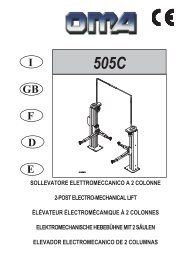
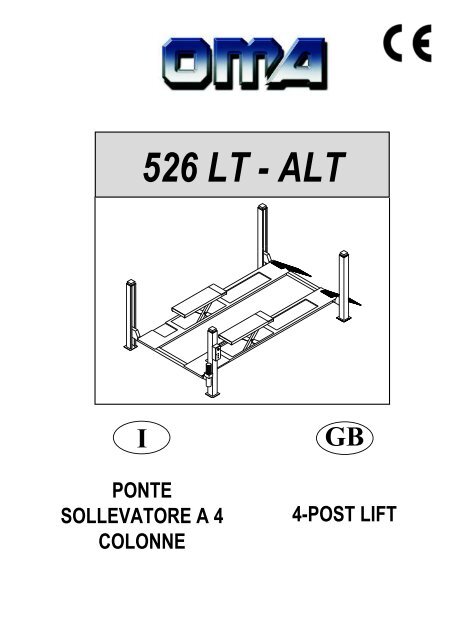
526 LT - <strong>ALT</strong><br />
I<br />
PONTE<br />
SOLLEVATORE A 4<br />
COLONNE<br />
GB<br />
4-POST LIFT
Manuale di istruzioni per l’ uso e la<br />
manutenzione dei<br />
SOLLEVATORE ELETTROIDRAULICO<br />
PER VEICOLI<br />
Modello 526 LT - <strong>ALT</strong><br />
Instruction manual for using and<br />
maintaining<br />
ELECTRO-HYDRAULIC LIFTS FOR VEHICLES<br />
Model526 LT - <strong>ALT</strong><br />
Matricola N°<br />
Anno di costruzione<br />
Serial No.<br />
Year of manufacture<br />
COSTRUTTORE:<br />
OMA S.p.A.<br />
Sede centrale: Via dell’Artigianato, 64<br />
36045 LONIGO (VI) -ITALY<br />
Telefono ++ / +444 / 436199<br />
Telefax ++ / +444 / 436208<br />
MANUFACTURER:<br />
OMA S.p.A.<br />
Head Office: Via dell’Artigianato, 64<br />
36045 LONIGO (VI) -ITALY<br />
Telefono ++ / +444 / 436199<br />
Telefax ++ / +444 / 436208<br />
1° Emissione - 04 Giugno 1999<br />
1rd Edition - 01 th June 1999<br />
CENTRO DI ASSISTENZA AUTORIZZATO:<br />
AUTHORIZED SERVICE CENTRE:<br />
Rev.16 .............................24/09/2008
Indice<br />
Imballaggio, trasporto<br />
e stoccaggio Pag. 3<br />
Introduzione Pag. 4<br />
Cap.1<br />
Descrizione della<br />
macchina Pag. 6<br />
Cap.2 Specifiche tecniche Pag. 9<br />
Cap.3 Sicurezza Pag.15<br />
Cap.4 Installazione Pag.22<br />
Cap.5 Funzionamento ed uso Pag.33<br />
Cap.6 Manutenzione Pag.34<br />
Cap.7 Inconvenienti e rimedi Pag.37<br />
Appendice A<br />
Informazioni<br />
particolari<br />
Pag.38<br />
Appendice B Parti di ricambio Pag.38<br />
Contents<br />
Packing, transport and storage Page 3<br />
Introduction Page 4<br />
Chapter 1<br />
Description of the<br />
machine Page 6<br />
Chapter 2 Specifications Page 9<br />
Chapter 3 Safety Page 15<br />
Chapter 4 Installation Page 22<br />
Chapter 5<br />
Operating<br />
principles and use Page 33<br />
Chapter 6 Maintenance Page 34<br />
Chapter 7 Troubleshooting Page 37<br />
Appendix A Special notes Page 38<br />
Appendix B Spare parts Page 38<br />
2
IMBALLAGGIO, TRASPORTO E<br />
STOCCAGGIO.<br />
LE OPERAZIONI DI IMBALLAGGIO, SOLLEVA-<br />
MENTO, MOVIMENTAZIONE, TRASPORTO E DI-<br />
SIMBALLO DEVONO ESSERE AFFIDATE ESCLU-<br />
SIVAMENTE A PERSONALE CHE SIA ESPERTO<br />
IN TALI OPERAZIONI E CHE CONOSCA BENE IL<br />
PONTE SOLLEVATORE ED IL PRESENTE MA-<br />
NUALE<br />
IMBALLAGGIO<br />
Il ponte sollevatore viene spedito smontato nei seguenti pezzi:<br />
Peso di un pezzo (Kg)<br />
4 colonne 50<br />
2 traverse 110<br />
2 rampe di salita 30<br />
2 fermaruote 2,6<br />
2 pedane: lato comando 650<br />
lato opposto 560<br />
1 assieme centralina 30<br />
1 quadro elettrico 15<br />
Il ponte sollevatore viene spedito avvolto in un unico pacco confezionato<br />
con una lastra di materiale termoretraibile e sigillato con<br />
due regge metalliche (Fig.1).<br />
Il peso medio del pacco è di circa 1800 Kg.<br />
SOLLEVAMENTO E MOVIMENTAZIONE<br />
I pacchi possono essere sollevati e spostati soltanto con carrelli<br />
elevatori, mantenendo una distanza di almeno 90 cm tra i due<br />
bracci della forca (Fig.1).<br />
Sollevare un solo pacco per volta.<br />
I mezzi scelti devono essere idonei al sollevamento e spostamento<br />
in sicurezza, tenendo conto di dimensioni, peso, baricentro del<br />
pacco, sporgenze, parti delicate da non danneggiare.<br />
PACKING, TRANSPORT AND<br />
STORAGE.<br />
PACKING, LIFTING, HANDLING, TRANSPORTING<br />
AND UNPACKING OPERATIONS MUST BE PER-<br />
FORMED ONLY BY EXPERIENCED PERSONNEL<br />
WITH APPROPRIATE KNOWLEDGE OF THE LIFT<br />
AND AFTER READING THIS MANUAL<br />
PACKING<br />
The lift is shipped disassembled in the following units:<br />
Unit weight (kg)<br />
4 posts 50<br />
2 crossbeams 110<br />
2 vehicle ramps 30<br />
2 wheel stops 2,6<br />
2 platform: control side 650<br />
opposite side 560<br />
1 hydraulic power unit 30<br />
1 control panel 15<br />
The lift is shipped in a single pack enclosed by a sheet of heat<br />
shrink material and restrained by two steel straps (fig.1).<br />
The average weight of the pack is 1800 kg.<br />
LIFTING AND HANDLING<br />
The packs can be lifted and transported only using lift trucks,<br />
and keeping the fork arm centres at least 90 cm apart (Fig.1).<br />
Lift only one pack at a time.<br />
The lifting equipment must be capable of lifting and moving the<br />
packs in complete safety, bearing in mind the dimensions, weight<br />
and centre of gravity of the pack, any protruding parts, and delicate<br />
parts to protect from impact damage etc..<br />
Fig.1<br />
Fig.1<br />
Imballo e spostamento<br />
Packing and moving<br />
Fig.2<br />
Fig.2<br />
Non sollevare o spostare MAI il sollevatore mediante fascie o<br />
imbracature per il sollevamento (Fig.2).<br />
STOCCAGGIO<br />
Gli imballi devono sempre essere conservati in luoghi coperti e protetti<br />
a temperature comprese fra -10 °C e + 40°C. e non devono<br />
essere esposti ai raggi diretti del sole.<br />
IMPILAMENTO DEI PACCHI<br />
E’ sempre sconsigliato in quanto il pacco non è previsto per l’impilamento.<br />
La base stretta, il peso notevole e la consistenza dell’imballo<br />
rendono problematico e delicato l’impilamento.<br />
Qualora si rendesse necessario l’impilamento, occorre adottare<br />
molte precauzioni e in particolare:<br />
- non superare mai i due metri di altezza della pila;<br />
- non fare mai pile di pacchi singoli, ma fare sempre pile di pacchi a<br />
coppie incrociate tra loro, in modo da ottenere cataste con una<br />
base più larga ed una certa stabilità; quindi provvedere a rendere<br />
sicuro lo stoccaggio, utilizzando regge, legacci o altri mezzi idonei.<br />
Nei cassoni dei camion, nei container, nei vagoni ferroviari si<br />
possono impilare al massimo due pacchi, purchè vengano<br />
reggiati tra loro e assicurati contro la caduta.<br />
NEVER attempt to hoist or transport the unit using lifting<br />
slings (Fig.2).<br />
STORAGE<br />
The packs must be kept in a covered and protected area in a temperature<br />
range of -10°C to +40°C. They must not be exposed to direct<br />
sunlight.<br />
STACKING THE PACKS<br />
We advise against stacking because the packs are not designed<br />
for this type of storage. The narrow base, heavy weight and large<br />
size of the packs make stacking difficult and potentially dangerous.<br />
If stacking is unavoidable, use all appropriate precautions:<br />
- never stack to more than 2 metres in height;<br />
- never make stacks of single packs, always stack pairs of packs in<br />
a cross pattern so that the base is bigger and the resulting stack is<br />
more stable; once the stack is complete, restrain it using straps, ropes<br />
or other suitable methods.<br />
A maximum of two packs can be stacked on lorries, in containers,<br />
and in railway wagons, on the condition that the packs<br />
are strapped together and restrained to stop them falling.<br />
3
APERTURA DEGLI IMBALLI<br />
All’arrivo verificare che la macchina non abbia subito danni durante<br />
il trasporto e che ci siano tutti i pezzi indicati nella lista di spedizione.<br />
I pacchi devono essere aperti adottando tutte le precauzioni per<br />
evitare danni alle persone (tenersi a distanza di sicurezza mentre<br />
si aprono le regge) e danni ai pezzi della macchina (evitare cadute<br />
di pezzi dal pacco durante l’apertura).<br />
É necessario prestare particolare attenzione per non danneggiare<br />
la centralina oleodinamica, il quadro comando e il cilindro<br />
montato sulla pedana.<br />
ELIMINAZIONE DELL’IMBALLO<br />
Il termoretraibile deve essere smaltito come rifiuto, secondo la normativa<br />
vigente per il riciclo dei materiali plastici nel paese di installazione<br />
del ponte sollevatore.<br />
OPENING THE PACKS<br />
When the lift is delivered make sure that it has not been damaged<br />
during transportation and that all the parts specified on the packing<br />
list are effectively present.<br />
Packs must be opened adopting all the precautions required to<br />
avoid injury to persons (keep at a safe distance when cutting the<br />
straps) or damage to parts of the machine (be careful that no parts<br />
are dropped while you are opening the packing).<br />
Take special care with the hydraulic power unit, the control<br />
panel and the platform cylinder.<br />
DISPOSAL OF PACKING MATERIAL<br />
The heat shrink plastic sheeting must be disposed of as waste material<br />
in conformity with the laws for recycling of plastics in the<br />
country of installation of the lift.<br />
INTRODUZIONE<br />
ATTENZIONE<br />
Questo manuale è stato scritto per il personale di officina addetto<br />
all’uso del sollevatore (operatore) e per il tecnico addetto<br />
alla manutenzione ordinaria (manutentore) pertanto, prima<br />
di effettuare qualsiasi operazione sul sollevatore e/o sul suo<br />
imballaggio, occorre leggere attentamente tutto il manuale,<br />
poichè esso contiene informazioni importanti per:<br />
- LA SICUREZZA DELLE PERSONE addette all’uso ed alla manutenzione<br />
ordinaria,<br />
- LA SICUREZZA DEL SOLLEVATORE,<br />
- LA SICUREZZA DEI VEICOLI sollevati.<br />
CONSERVAZIONE DEL MANUALE<br />
Il manuale è parte integrante del sollevatore e deve sempre accompagnarlo,<br />
anche in caso di vendita.<br />
Esso deve sempre essere conservato in vicinanza del ponte sollevatore,<br />
in luogo facilmente accessibile.<br />
L’operatore ed il manutentore devono poterlo reperire e consultare<br />
rapidamente in qualsiasi momento.<br />
SI RACCOMANDA, IN PARTICOLARE, UNA LETTURA ATTENTA<br />
E RIPETUTA DEL CAPITOLO 3, CHE CONTIENE IMPORTANTI<br />
INFORMAZIONI E AVVISI RELATIVI ALLA SICUREZZA.<br />
INTRODUCTION<br />
WARNING<br />
This manual has been prepared for workshop personnel expert<br />
in the use of the lift (operator) and technicians responsible<br />
for routine maintenance (maintenance fitter); read the manual<br />
before carrying out any operation with the lift and/or the<br />
packaging. This manual contains important information regarding:<br />
- THE PERSONAL SAFETY of operators and maintenance workers,<br />
- LIFT SAFETY,<br />
- THE SAFETY OF LIFTED VEHICLES<br />
KEEPING THE MANUAL<br />
The manual is an integral part of the lift , and must be always<br />
kept with it , even in the case of sale of the unit.<br />
The manual must be kept next to the lift, in an easily accessible<br />
place.<br />
The operator and maintenance staff must be able to locate and<br />
consult the manual quickly and at any time.<br />
ATTENTIVE AND REPEATED READING OF CHAPTER 3,<br />
WHICH CONTAINS IMPORTANT SAFETY INFORMATION AND<br />
WARNINGS, IS PARTICULARLY RECOMMENDED.<br />
I ponti sollevatori sono stati progettati e costruiti rispettando quanto<br />
segue:<br />
LEGGI:<br />
Direttive europee: 98/37/CE-2004/108/CE-2006/95/CE<br />
NORME TECNICHE:<br />
Norme europee: EN 1493/ EN 292-1/ EN 292-2<br />
IMPIANTO ELETTRICO:<br />
UNI EN 60204, CEI 64/8<br />
Lifts are designed and built in compliance with:<br />
LAWS:<br />
European directives: 98/37/CE-2004/108/CE-2006/95/CE<br />
TECHNICAL STANDARDS:<br />
European standards: EN 1493/ EN 292-1/ EN 292-2<br />
ELECTRICAL SYSTEM:<br />
UNI EN 60204, CEI 64/8<br />
4
Il sollevamento, il trasporto, il disimballo, il montaggio, l’installazione<br />
e la messa in servizio, la taratura e le registrazioni iniziali, la<br />
manutenzioneSTRAORDINARIA, la riparazione, la revisione, lo<br />
spostamento e lo smantellamento del sollevatore devono essere<br />
eseguiti dai tecnici specializzati dei RIVENDITORI AUTORIZZATI<br />
o dei CENTRI ASSISTENZA AUTORIZZATI dal Costruttore (vedere<br />
centro assistenza autorizzato indicato nel frontespizio):<br />
Il costruttore non risponde di alcun danno a persone, veicoli<br />
od oggetti causati dagli interventi sopracitati se effettuati da<br />
personale non autorizzato o da un uso improprio o non consentito<br />
del ponte sollevatore<br />
Per tutte queste attività vengono indicati, nel presente manuale,<br />
soltanto gli aspetti (operativi e di sicurezza) che possono essere<br />
utili anche all’operatore ed al manutentore per comprendere meglio<br />
la struttura ed il funzionamento del sollevatore e per un suo migliore<br />
utilizzo.<br />
Per comprendere il linguaggio adottato nel presente manuale, l’operatore<br />
deve possedere esperienza specifica nelle attività di officina,<br />
di assistenza, manutenzione e riparazione dei veicoli nonchè la<br />
capacità di interpretare correttamente i disegni e le descrizioni riportate<br />
nel manuale e la conoscenza delle norme antinfortunistiche<br />
generali e specifiche vigenti nel paese in cui viene installato il sollevatore.<br />
Gli stessi criteri valgono per la scelta del tecnico manutentore che<br />
dovrà, inoltre, possedere le conoscenze tecniche specifiche e specialistiche<br />
(meccaniche, elettriche) necessarie per effettuare in sicurezza<br />
gli interventi previsti nel manuale.<br />
Nel testo del manuale troverete spesso le diciture “operatore” e<br />
“manutentore” il cui significato è il seguente:<br />
OPERATORE: persona addetta all’uso del sollevatore.<br />
MANUTENTORE: persona addetta alla manutenzione ordinaria del<br />
sollevatore.<br />
Lifting, transport, unpacking, assembly, installation and commissioning,<br />
adjustment and initial set-ups, NON-ROUTINE maintenance,<br />
overhauling, moving and taking down of the lift must always be<br />
performed by qualified personnel from AUTHORISED DEALERS<br />
or LICENSED SERVICE CENTRES (contact your licensed service<br />
centre indicated on the title page of this manual):<br />
The manufacturer will not be held liable for personal injury or<br />
damage to vehicles or property caused by improper and/or<br />
unauthorised use of the lift.<br />
In respect of all the above mentioned activities, this manual covers<br />
only such operational and safety aspects that are considered useful<br />
for operators and maintenance personnel to gain a more complete<br />
understanding of the structure and functions of the lift so that<br />
it can be used in the best way.<br />
To ensure adequate comprehension of the technical language in<br />
this manual the operator must have specific experience of workshop<br />
procedures for servicing, maintenance and repair of vehicles<br />
and must also be capable of interpreting the drawings and descriptions<br />
in the manual and be aware of general and specific accident<br />
prevention regulations in force in the country of installation.<br />
The same considerations apply to the maintenance fitter who must<br />
also possess specific technical (mechanical and electrical) skills<br />
necessary to perform the various interventions described in the<br />
manual in conditions of total safety.<br />
The words “operator” and “maintenance fitter” are used with the following<br />
meaning in the manual:<br />
OPERATOR: person in charge of using the lift.<br />
MANUTENANCE FITTER: person in charge of routine maintenance<br />
of the lift.<br />
5
CAP.1.<br />
DESCRIZIONE DELLA<br />
MACCHINA<br />
CHAPTER 1.<br />
DESCRIPTION<br />
OF THE MACHINE<br />
I ponti sollevatori a 4 colonne sono fissi, cioè ancorati al suolo;<br />
sono progettati e costruiti per il sollevamento e lo stazionamento in<br />
quota di autoveicoli e furgoni.<br />
Sono composti principalmente da una parte fissa, ancorata al terreno<br />
(colonne) e da una parte mobile (traverse e pedane di sostegno<br />
e sollevamento).<br />
Il funzionamento è di tipo elettroidraulico.<br />
Questi sollevatori sono composti, fondamentalmente da quattro<br />
parti:<br />
- gruppo struttura fissa;<br />
- gruppo struttura mobile;<br />
- gruppo di sollevamento;<br />
- sicurezze.<br />
In figura 3 sono indicate le varie parti che compongono il sollevatore<br />
e le zone di lavoro attorno al sollevatore stesso.<br />
Lato operatore: è il lato anterioredel sollevatore, quello che comprende<br />
anche la zona riservata all’operatore in cui si accede al<br />
quadro comandi ed è opposta al lato di ingresso del sollevatore.<br />
Lato posteriore: è il lato opposto a quello operatore in cui si trovano<br />
le rampe di accesso al sollevatore.<br />
Lati destro e sinistro: sono stabiliti rispetto all’operatore rivolto verso<br />
il sollevatore.<br />
Zona di rischio: è la zona di sicurezza in cui non si deve mai sostare<br />
quando il sollevatore è in funzione; spiegazioni maggiormente<br />
dettagliate le troverete nel capitolo 3 “Sicurezze”.<br />
La numerazione in figura 3 si riferisce a:<br />
1 colonna lato comando (si intende per<br />
convenzione interna come anteriore destra)<br />
2 colonna anteriore sinistra<br />
3 colonna posteriore sinistra<br />
4 colonna posteriore destra<br />
5 traversa lato comando (traversa anteriore)<br />
6 traversa traversa posteriore<br />
7 pedana destra, fissa<br />
8 pedana sinistra, mobile<br />
9 torrette<br />
Four-post lifts are fixed installations, i.e. anchored to the floor; the<br />
units are designed and built for lifting cars and vans and holding<br />
them in an elevated position.<br />
The units are essentially made up of a fixed part that is anchored<br />
to the floor (posts) and a moving part (cross-pieces and platforms).<br />
The operation is electro-hydraulic<br />
There are four basic parts of the lifts:<br />
- fixed structure assembly;<br />
- movable structure assembly;<br />
- lifting assembly;<br />
- safety devices.<br />
Figure 3 shows the various parts of the lift and the operating zones<br />
in the surrounding area.<br />
Operator side: this is the front of the lift, including the area reserved<br />
for the operator with the control panel. The operator side is opposite<br />
the vehicle access side.<br />
Rear side: it is the side opposed the operator’s one, with the lift access<br />
ramps.<br />
Right and left sides: the right and left is considered from the operator’s<br />
standpoint when facing the lift.<br />
Danger zone: an area that must be kept clear of persons when the<br />
lift is in use; refer to “Safety devices” chapter 3 for details.<br />
Key to figure 3:<br />
1 control side post (conventionally the front right-hand post)<br />
2 front left post<br />
3 rear left post<br />
4 rear right post<br />
5 control side cross-piece (front cross-piece)<br />
6 rear cross-piece<br />
7 right fixed platform<br />
8 left moving platform<br />
9 lift-table<br />
3<br />
2<br />
8<br />
6<br />
4<br />
9<br />
7<br />
5<br />
1<br />
Zona operatore<br />
Operator area<br />
Fig.3<br />
6
GRUPPO STRUTTURA FISSA<br />
E’ costituita da quattro colonne verticali in lamiera di acciaio piegata<br />
alla cui base è saldata una piastra forata che permette il fissaggio<br />
al suolo mediante tasselli ad espansione (vedere capitolo 4 “<br />
installazione”).<br />
All’interno di ogni colonna sono alloggiati:<br />
- un’asta di sicurezza con asole (1) per l’appoggio dei martelletti di<br />
sicurezza,<br />
- una fune in acciaio per il sollevamento (2),<br />
- una guida per lo scorrimento verticale delle traverse.<br />
FIXED STRUCTURE ASSEMBLY<br />
The structure includes the four vertical posts in bent steel plate<br />
with a pre-drilled baseplate for expansion anchors to secure the<br />
unit to the floor (see chapter 4 “Installation”).<br />
Each post houses:<br />
- a safety rod with slots (1) to engage the safety wedges,<br />
- a steel cable for lifting (2),<br />
- a guide for the cross-piece vertical sliding (3).<br />
1<br />
3<br />
5<br />
2<br />
4<br />
Fig.4<br />
Fig.4<br />
Colonna<br />
Post<br />
Fig.5<br />
Fig.5<br />
Sommità colonne<br />
Post top<br />
Sulla sommità di ogni colonna sono ancorate:<br />
- l’estremità dell’asta di sicurezza (4), (fissata con dado e controdado<br />
M20, classe di resistenza 8.8) ;<br />
- l’estremità della fune in acciaio (5), che ha un codulo filettato M20<br />
(fissato con dado e controdado M20, classe di resistenza 6S).<br />
La lunghezza del codulo filettato consente la perfetta registrazione<br />
delle funi, o la ripresa di un loro eventuale<br />
allungamento.<br />
Alla colonna comando (Fig. 6) sono fissati il<br />
quadro elettrico di comando e la centralina<br />
idraulica.<br />
Sul pannello del quadro elettrico di comando<br />
sono installati:<br />
- l’interruttore generale (1),<br />
- pulsante di avvio (2)<br />
- selettore lift/lift table (3)<br />
- il pulsante di salita lift (4),<br />
- il pulsante di discesa lift (5);<br />
- il pulsante di stazionamento lift (6)<br />
- il pulsante di salita lift table(7),<br />
- il pulsante di discesa lift table(8);<br />
La centralina idraulica è composta da:<br />
- un motore elettrico di comando (10),<br />
- una pompa idraulica ad ingranaggi (11),<br />
- un’elettrovalvola di discesa (12),<br />
- una vite di messa in scarico manuale del<br />
ponte (13),<br />
- una valvola di massima pressione (14),<br />
- una valvola di deviazione lift/lift table (15),<br />
- un serbatoio olio (16),<br />
- un tubo flessibile di mandata olio lift (17),<br />
- un tubo flessibile di mandata olio lift table<br />
(18),<br />
- un tubo flessibile per il recupero dell’olio<br />
(19).<br />
NOTA:<br />
l tubi di mandata olio (17 e 18) possono trovarsi<br />
in pressione.<br />
Il tubo di recupero olio (19) non è mai in<br />
pressione.<br />
10<br />
12<br />
13<br />
15<br />
7<br />
18<br />
19<br />
8<br />
The following parts are anchored to the top of each post:<br />
- end of safety rod (4), (secured with M20 nut and lock nut, class<br />
8.8);<br />
- the end of the steel cable (5), which is fitted with an M20 threaded<br />
shank (fixed with M20 nut and lock nut, class 6S).<br />
The length of the cables can be perfectly adjusted - also to take up<br />
slack due to stretching, thanks to the length<br />
of the threaded shanks on the ends of the<br />
cables.<br />
1<br />
2<br />
3<br />
4<br />
6<br />
5<br />
11<br />
14<br />
17<br />
The drive post (Fig.6) mounts the electrical<br />
control panel and the hydraulic power unit.<br />
The following components are present on the<br />
control panel:<br />
- main switch (1),<br />
- start push button (2),<br />
- lift/lift table selector (3),<br />
- lift up button (4),<br />
- lift down button (5);<br />
- lift stop push button (6)<br />
- lift table up button (7),<br />
- lift table down button (8);<br />
The hydraulic power unit comprises:<br />
- motor (10),<br />
- hydraulic gear pump (11),<br />
- lowering solenoid valve (12),<br />
- manual lowering screw (13),<br />
- relief valve (14),<br />
- lift/lift table deviation solenoid valve (15),<br />
- oil reservoir (16),<br />
- lift oil delivery hose (17),<br />
- lift table oil delivery hose (18),<br />
- oil drain hose (19)<br />
NOTE:<br />
The delivery hoses (17 and 18) are sometimes<br />
pressurised;<br />
the drain hose (19) is never pressurised.<br />
Fig.6<br />
Pannello di comando e centralina idraulica.<br />
16<br />
Fig.6<br />
Control panel and hydraulic power unit.<br />
7
GRUPPO STRUTTURA MOBILE<br />
É costituito da due traverse e da due pedane.<br />
Ogni traversa scorre verticalmente tra due colonne.<br />
Come si vede in fig.7, alle due estremità di ogni traversa sono fissati:<br />
- le pulegge di rinvio (1) della fune di sollevamento,<br />
- gli innesti meccanici di sicurezza (martelletti) (2 e 3).<br />
Il martelletto di stazionamento (pos.3) si inserisce automaticamente<br />
durante tutta la fase di salita e nello stazionamento. Deve essere<br />
disinserito elettricamente durante la fase di discesa.<br />
MOVABLE STRUCTURE<br />
The movable structure consist of two cross-pieces and two platforms.<br />
Each cross-piece translates vertically between two posts.<br />
As shown in fig.7, the ends of the cross-pieces are fitted with the<br />
following parts:<br />
- return pulleys (1) for the lift cable,<br />
- mechanical safety devices (wedges) (2 and 3).<br />
The wedge (pos. 3) will engage automatically during lifting and<br />
when the lift is raised.<br />
In caso di rottura della fune, si azio-na il microinterruttore funi (4)<br />
che provoca il blocco della parte elettrica del ponte e l’inserimento<br />
del martelletto di stazionamento, pertanto della sua parte mobile<br />
nonchè del carico.<br />
In case of breakage of the cable, the cable micro switch (4) causes<br />
the lock of the lift electrical part and the engagement of the safety<br />
wedge, therefore it stops the movable part and the relevant vehicle.<br />
Fig.7<br />
1<br />
4<br />
Fig.8<br />
1<br />
4<br />
2<br />
2<br />
3<br />
3<br />
Le due pedane portaveicoli (Fig. 9) appoggiano sulle traverse.<br />
La pedana sinistra (1) è fissa, mentre la pedana destra (2) è mobile<br />
e può scorrere orizzontalmente per adattarsi alle diverse carreggiate<br />
dei veicoli. Entrambe sono dotate di bordi interni (3) di contenimento<br />
dei pneumatici del veicolo e di arresti fissi di sicurezza (4)<br />
che impediscono al veicolo stesso di oltrepassare accidentalmente<br />
la fine della pedana; le rampe di accesso (5), incernierate sulle pedane,<br />
si posizionano verticalmente quando le pedane salgono,<br />
bloccando in maniera definitiva il veicolo.<br />
he two platforms (Fig. 9) are supported on the cross-pieces.<br />
The left platform (1) has no adjustment; the right platform (2) is free<br />
to slide across the width of the lifting area to adapt to the track<br />
width of the vehicle being lifted.<br />
Both platforms have inside kerbs (3) to keep the vehicle tyres fully<br />
on the lifting surface, and fixed wheel stops (4) to stop the vehicle<br />
from going beyond the ends of the platforms;<br />
The access ramps (5), pivoted to the platforms, automatically reach<br />
a vertical position when the platforms lift, thereby securing the<br />
vehicle also from the access end.<br />
1<br />
2<br />
3<br />
3<br />
Fig.9<br />
Pedane e Traverse<br />
Fig.9<br />
Platforms and cross-pieces<br />
All’interno della pedana lato comando<br />
(Fig. 10), con accesso dal<br />
solo lato inferiore (lato suolo),<br />
si trovano:<br />
- il cilindro idraulico di sollevamento<br />
(1);<br />
- la valvola paracadute o di blocco<br />
(2);<br />
- il giogo di attacco (3) delle funi di<br />
acciaio;<br />
- due gruppi pulegge di rinvio (4)<br />
delle funi.<br />
1<br />
4<br />
3<br />
The following components are located<br />
beneath the fixed platform (Fig.<br />
10), and are accessible only from<br />
underneath:<br />
- hydraulic lift cylinder (1);<br />
- parachute safety valve (2);<br />
- clevis coupling (3) for the steel<br />
cables;<br />
- two cable return pulley assemblies<br />
(4).<br />
2<br />
Fig.10-<br />
Interno pedana fissa<br />
4<br />
FiIg.10<br />
Interior of the fixed platform<br />
8
CAP.2.<br />
SPECIFICHE TECNICHE<br />
CHAPTER 2<br />
SPECIFICATIONS<br />
PORTATA pedane ....................................5000 kg (49030 N)<br />
PORTATA lift tables ..................................4000 kg (39225 N)<br />
Alt. max. sollevamento auto ......................1830 mm<br />
Alt. min. supporti sollevamento .................190 mm<br />
Interasse longitudinale colonne.................4910 mm<br />
Interasse trasversale colonne ...................3090 mm<br />
Larghezza libera tra colonne.....................2970 mm<br />
Larghezza pedane.....................................680 mm<br />
Lunghezza pedane....................................5200 mm<br />
Tempo di salita..........................................50 sec<br />
Tempo di discesa ......................................45 sec.<br />
FUNE di sollevamento in acciaio, con le seguenti caratteristiche:<br />
Diametro....................................................11 mm<br />
Numero di fili .............................................227<br />
Resistenza dei fili ......................................1960 N<br />
Diametro primitivo pulegge........................220 mm<br />
Rumorosità................................................70dB(A)/1m<br />
PESO totale del sollevatore .....................circa 1800 Kg<br />
Temperatura di funzionamento .................-10°C / + 50°C<br />
Pressione di lavoro....................................185 bar<br />
Ambiente di lavoro: locale chiuso.<br />
CAPACITY platforms................................. 5000 kg (49030N)<br />
CAPACITY lift tables ................................. 4000 kg (39225 N)<br />
Max. vehicle lifting height ..........................1830 mm<br />
Min. ground clearance of lift structure .......190 mm<br />
Longitudinal C/C distance between posts .4910 mm<br />
Transverse C/C distance between posts...3090 mm<br />
Effective clearance between posts............2970 mm<br />
Platform width............................................680mm<br />
Platform length ..........................................5200 mm<br />
Lift time......................................................50 sec<br />
Lowering time............................................45 sec<br />
LIFTING CABLES in steel, having the following features:<br />
Diameter....................................................11 mm<br />
Strands......................................................227<br />
Tensile strength of strand..........................1960 N<br />
Pulley pitch diameter.................................220 mm<br />
Noise .........................................................70dB(A)/1m<br />
OVERALL WEIGHT of lift unit ...................1800 kg approx.<br />
Working temperature range.......................-10°C / + 50°C<br />
Working pressure ......................................185 bar<br />
Installation requirements: enclosed area.<br />
Fig.11 - Dimensioni ed ingombri<br />
Fig.11 - Overall dimensions and clearances<br />
MOTORE ELETTRICO<br />
Tipo ..........................................C90<br />
Potenza ....................................3 KW<br />
Voltaggio ..................................230-400V trif. +/-5%<br />
Frequenza ................................50 Hz<br />
N° poli.......................................4<br />
Velocità ....................................1400 giri/1’<br />
Forma costruttiva .....................B 14<br />
Classe isolamento....................F<br />
Assorbimento ...........................230V: 15A<br />
.................................................400V: 8,7A<br />
MOTOR<br />
Type .............................C90<br />
Power...........................3 kW<br />
Voltage.........................230-400V th.-ph. +/-5%<br />
Frequency ....................50 Hz<br />
Poles ............................4<br />
Speed...........................1400 rpm<br />
Building shape..............B 14<br />
Insulation class.............F<br />
Absorption....................230V: 15A<br />
.....................................400V: 8,7A<br />
Il collegamento del motore deve essere eseguito riferendosi<br />
agli schemi elettrici allegati.Il senso di rotazione del motore è<br />
sinistro (antiorario) come indicato nella targhetta applicata sul<br />
motore stesso.<br />
When connecting the motor refer to the enclosed wiring<br />
diagrams.<br />
The motor has left-handed rotation (counter-clockwise) as<br />
shown on the data plate on the casing.<br />
9
CENTRALINA OLEODINAMICA<br />
Possono venire montate, indipendentemente dal modello del ponte,<br />
due diverse centraline oleodinamiche, ovvero le parti, componenti<br />
la pompa, che traducono il movimento del motore in spinta<br />
dell’olio nei tubi. In figura 12 è mostrato il tipo K3 (OIL SISTEM).<br />
HYDRAULIC POWER UNIT<br />
Irrespective of the model, the lift can be supplied with an option of<br />
two different hydraulic power units, i.e. the various components of<br />
the pump that convert the rotary motion of the motor into fluid pressure<br />
for the hydraulic circuit.Figure 12 show the type K3 (OIL<br />
SISTEM).<br />
POMPA<br />
Tipo ...........................................................18<br />
Modello......................................................10A5X348N<br />
Cilindrata ...................................................5 cm3/g<br />
Taratura valvola di massima .....................200 bar<br />
PUMP<br />
Type ...................................................................18<br />
Model ..................................................................10A5X348N<br />
Displacement ......................................................5 cc/rev.<br />
Relief valve set-up ..............................................200 bar<br />
Fig.12- Centraline<br />
Fig.12 - Hydraulic power units<br />
1 Valvola di ritegno Check valve<br />
2 Elettrovalvola di discesa Lowering solenoid valve<br />
3 Scarico manuale Manual outlet<br />
4 Elettrovalvola deviazione lift/lift table Lift/ lift table deviation solenoid valve<br />
5 Carico olio sollevatore Lift delivery<br />
6 Carico olio lift table Lift table delivery<br />
7 Tubo per recupero olio Drain hose<br />
8 Valvola regolatrice di scarico Outlet adjusting valve<br />
9 Valvola massima pressione Relief valve<br />
OLIO<br />
Il serbatoio dell’olio contiene olio idraulico a base minerale secondo<br />
normativa ISO/DIN 6743/4 con grado di contaminazione non<br />
superiore alla classe 18/15 secondo normativa ISO 4406 come IP<br />
HYDRO OIL 32; SHELL TELLUS T 37 o equivalenti.<br />
OIL<br />
The hydraulic oil reservoir is filled with mineral oil to ISO/DIN<br />
6743/4, contamination category no higher than class 18/15 according<br />
to ISO 4406, such as IP HYDRO OIL 32; SHELL TELLUS T<br />
37 or an equivalent oil.<br />
10
SCHEMI ELETTRICI ED OLEODINAMICI<br />
WIRING DIAGRAMS AND HYDRAULIC<br />
11
SCHEDA ELETTRICA<br />
ELECTRIC BOARD<br />
VERIFICARE L’ESATTA POSIZIONE DEI RELE’<br />
CHECK THE CORRECT RELAYS POSITION<br />
LEGENDA SCHEMA ELETTRICO<br />
WIRING DIAGRAMS KEY<br />
Rif. Ref. Descrizione Description Marca<br />
Articolo<br />
Q.tà<br />
Brand<br />
Article<br />
Q.ty<br />
C1-C2 Elettromagnete Electromagnet E0425 24V CC 50Hz 2<br />
C3 Elettrovalvola Solenoid valve OIL SISTEM 24VAC 50/60Hz ED100% 1<br />
C4 Elettrovalvola deviazione L.T. L.T. Deviation solenoid valve OIL SISTEM 24VAC 50/60Hz ED100% 1<br />
C5 Elettrovalvola pneumatica Pneumatic solenoid valve Pneumax LFKMB56 50/60Hz ED100% 1<br />
FU1 Portafusibile 10x38 Fuse carrier 10x38 WEBER PCH10x38+CH10x38 2<br />
F1 Portafusibile 5x20 Fuse carrier 5x20 Integrato nella scheda / Integrate in the electric board 1<br />
PTC Protezione termica Thermal limiter Integrato nel motore / Integrate in the motor 1<br />
QM1-QM4 Microinterruttori funi Cable microswitch PIZZATO FR1454 4<br />
QM5 Microinterruttore salita Lifting microswitch PIZZATO FR654 1<br />
QM11<br />
Microinteruttore discesa Lowering microswitch PIZZATO FR754<br />
1<br />
QS Interruttore generale Master switch SPRECHER<br />
LA2-16-1754+LFS2-N-6-175+<br />
1<br />
LA2-12-C4+LA2-G2853+LA2-G3195<br />
KM1 Teleruttore Motor contactor LC1D12 24V 50/60Hz 1<br />
K1 Relè elettromagneti Electromagnet relay FINDER 55.32.9.024.0040 1<br />
KA2 Relè discesa Lowering relay FINDER 55.34.9.024.0040 1<br />
KA3 Relè salita Lifting relay Integrato nella scheda / Integrate in the electric board 1<br />
KA4 Relè primario trasformatore Primary transformer relay FINDER 55.34.9.024.0040 1<br />
KT1 Relè TR1 (elettromagneti) TR1 relay (electromagnet) Integrato nella scheda / Integrate in the electric board 1<br />
KT2 Relè TR2 (discesa) TR2 relay (lowerin)g Integrato nella scheda / Integrate in the electric board 1<br />
TR1 Trimmer KT1 (elettromagneti) Trimmer KT1 (electromagnet ) Integrato nella scheda / Integrate in the electric board 1<br />
TR2 Trimmer KT2 (discesa) Trimmer KT2 (lowering ) Integrato nella scheda / Integrate in the electric board 1<br />
M Motore elettrico Electric motor 230/400V 50Hz 1<br />
SA1 Selettore 1-0-2 Selector switch 1-0-2<br />
ZB5-BD3+ZB5AZ009+(ZBE101x)+(ZB 1<br />
E102x2)<br />
SB1 Pulsante salita Lifting button HB7EA21P (1NO) 1<br />
SB2 Pulsante discesa Lowering button ZB5AA2+ZB5AZ009+(ZBE101x2) 1<br />
SB3 Pulsante stazionamento Parking button<br />
ZB5AA8+ZB5AZ009+(ZBE101x2)+ZB 1<br />
E102<br />
SB4 Pulsante salita L.T. L.T. lifting button HB7EA21P (1NO) 1<br />
SB5 Pulsante discesa L.T. L.T. lowering button ZB5AA2+ZB5AZ009+(ZBE101x2) 1<br />
SB8 Pulsante inserzione macchina Machine connection button ZB5AA3+ZB5AZ009+(ZBE101x2) 1<br />
FR2 Interruttore magnetotermico Magnetic switch 20A TYPE C 1<br />
BZ1 Avvisatore acustico salvapiedi Warning siren Integrato nella scheda / Integrate in the electric board 1<br />
TM Trasformatore Transformer C.E. 230-400/24V 300VA 50/60Hz 1<br />
12
SCHEMA TOPOGRAFICO<br />
ATTENZIONE<br />
I cavi contrassegnati con colore Giallo possono essere in alternativa<br />
anche di colore Grigio.<br />
TOPOGRAPHIC DIAGRAM<br />
WARNING<br />
The marked cables with Yellow color could be in alternative<br />
also of Grey color.<br />
Quadro elettrico<br />
Control panel<br />
Micro funi<br />
Cable micro-switch<br />
Elettromagnete<br />
Electromagnet<br />
Micro funi<br />
Cable micro-switch<br />
Giallo -Yellow<br />
Nero-Black<br />
Giallo -Yellow<br />
Giallo - Yellow<br />
Nero - Black<br />
Nero-Black Giallo-Yellow<br />
Nero - Black<br />
Marrone -Braun<br />
Blu -Blau<br />
Marrone -Braun<br />
Blu - Blau<br />
Marrone -<br />
Braun<br />
Blu - Blau<br />
Marrone -Braun<br />
Blu - Blau<br />
Rosso 5-Red5<br />
Nero0-Black0<br />
Rosso 6-Red6<br />
Nero0-Black0<br />
Giallo - Yellow<br />
Nero - Black<br />
Giallo -Yellow<br />
Nero - Black<br />
Marrone - Braun<br />
Blu - Blau<br />
Marrone - Braun<br />
Blu - Blau<br />
Micro funi<br />
Cable micro-switch<br />
Micro funi<br />
Cable micro-switch<br />
Elettromagnete<br />
Electromagnet<br />
13
1<br />
Azzurro<br />
Blue sky<br />
16<br />
Nero<br />
Black<br />
21 NC 22<br />
13 NO 14<br />
QM11<br />
17<br />
Marron<br />
Brown<br />
18<br />
Grigio<br />
Grey<br />
Microinterruttore discesa pedane QM11 - Platforms LOWERING microswitch QM11 (1-17) (16-18)<br />
Microinterruttore salita pedane - Platforms LIFTING microswitch (3-4)<br />
Motore + protezione termica motore - Motor and thermal switch (8-9)<br />
Elettrovalvola pneumatica - Pneumatic solenoid valve (0-39)<br />
Elettrovalvola discesa - Lowering solenoid valve (0-7)<br />
Elettromagneti - Electromagnet (0-5) (0-6)<br />
1<br />
C12<br />
2<br />
C24<br />
3<br />
C26<br />
1 1<br />
4<br />
5<br />
5<br />
4<br />
C23<br />
4<br />
C25<br />
2<br />
D02<br />
D03<br />
13<br />
12<br />
14<br />
11<br />
10<br />
7<br />
8<br />
6<br />
9<br />
Rif./Ref.<br />
Descrizione / Description<br />
1 Cilindro / Cylinder<br />
Rif./Ref.<br />
Descrizione / Description<br />
1 Cilindro pedane / Platforms cylinder<br />
2 Cilindro primario L.T. / L.T. primary cylinder<br />
3 Cilindro secondario L.T. / L.T. secondary cylinder<br />
2 Elettrovalvola / Solenoid valve<br />
2 USCITA / OUT<br />
4 Valvola paracadute / Parachute valve<br />
5 Valvola livellamento / Leveling valve<br />
6 Motore / Motor<br />
7 Pompa / Pump<br />
8 Filtro / Filter<br />
9 Serbatoio / Reservoir<br />
CHIUSO /<br />
CLOSED<br />
ENTRATA /<br />
IN (3/8”)<br />
10 Valvola di massima / Relief valve<br />
11 Valvola di ritegno / Check valve<br />
COMANDO MANUALE / MANUAL COMMAND<br />
12 Elettrovalvola / Solenoid valve<br />
14
TIPI DI VEICOLI SOLLEVABILI E INGOMBRI<br />
I ponti sollevatori si adattano praticamente a tutti i veicoli di peso<br />
non superiore a 5000 kg e le cui dimensioni non eccedano quelle<br />
riportate di seguito.<br />
DIMENSIONI MASSIME DEI VEICOLI DA SOLLEVARE<br />
La larghezza non deve eccedere i 2400 mm.<br />
Il passo tra gli assi non deve eccedere i 4200 mm.<br />
La distanza massima tra i bordi esterni dei pneumatici, compreso il<br />
rigonfiamento a terra, non deve eccedere i 2000 mm.<br />
La distanza minima tra i bordi interni dei pneumatici, compreso il rigonfiamento<br />
a terra, non deve essere inferiore a 900 mm.<br />
L’ altezza minima da terra può interferire con le strutture del sollevatore.<br />
Fare attenzione soprattutto alle autovetture sportive.<br />
Eventuali carrozzati speciali possono essere sollevati tenendo però<br />
conto della portata del sollevatore.<br />
Anche la zona di rischio per le persone dovrà essere adeguata<br />
alle dimensioni speciali del veicolo.<br />
Gli schemi seguenti riportano i criteri per definire i limiti di impiego<br />
del sollevatore.<br />
TYPES OF VEHICLES SUITABLE FOR BEING LIFTED AND<br />
OVERALL DIMENSIONS<br />
Lifts are suitable for virtually all vehicles with total weight of no<br />
more than 5000 kg and with dimensions not exceeding the below<br />
data.<br />
MAXIMUM DIMENSIONS OF VEHICLES MAIN LIFTED<br />
Max. width: 2400 mm.<br />
Max. wheelbase: 4200 mm.<br />
Max. distance between outer wall of tyres, inclusive of bulge caused<br />
by weight of vehicle on ground: 2000 mm.<br />
Min. distance between inner walls of tyres, inclusive of bulge caused<br />
by weight of vehicle on ground: 900 mm.<br />
Caution: the lower parts of the vehicle underbody could interfere<br />
with structural parts of the lift.<br />
Take particular care in the case sports-cars.<br />
The lift will also handle customised or non-standard vehicles provided<br />
they are within the maximum specified carrying capacity.<br />
Also the personnel danger zone must be defined in relation to<br />
vehicles with unusual dimensions.<br />
The following diagrams illustrate criteria used to define the operating<br />
limits of the lift.<br />
B<br />
A<br />
C<br />
D<br />
Fig.13<br />
E<br />
Misure minime e massime<br />
PER INGOMBRI MAGGIORI VERIFICARE IL CARICO MASSIMO<br />
ED IL SUO SBILANCIAMENTO<br />
Min. (mm) Max. (mm)<br />
A - 4200<br />
B 100 -<br />
C - 2000<br />
D 900 -<br />
E - 2400<br />
Fig.13<br />
Maximum and minimum dimensions<br />
FOR LARGER DIMENSIONS CHECK THE MAXIMUM LOAD<br />
AND POSSIBLE UNBALANCE<br />
PESI MASSIMI DEI VEICOLI DA SOLLEVARE<br />
MAXIMUM WEIGHTS OF VEHICLES BEING LIFTED<br />
Fig.14<br />
Fig.14<br />
Ripartizione pesi “A”<br />
Weight distribution “A”<br />
Fig.15<br />
Fig.15<br />
Ripartizione pesi “B”<br />
Weight distribution “B”<br />
15
CAP.3<br />
SICUREZZA<br />
CHAPTER 3<br />
SAFETY<br />
É estremamente importante leggere questo capitolo attentamente<br />
ed in ogni sua parte poichè contiene importanti informazioni<br />
sui rischi che operatore e manutentore possono correre<br />
in caso di un uso errato del ponte sollevatore.<br />
Nel testo che segue troverete chiare spiegazioni su alcune situazioni<br />
di rischio o pericolo che si possono verificare durante<br />
l’uso e la manutenzione del sollevatore, sui dispositivi di sicurezza<br />
adottati e sul loro uso corretto, sui rischi residui e sui<br />
comportamenti da tenere (precauzioni generali e specifiche<br />
per eliminarli o neutralizzarli).<br />
ATTENZIONE:<br />
I sollevator sono stati progettati e costruiti per il<br />
sollevamento e lo stazionamento in quota dei veicoli<br />
in ambiente chiuso. Ogni altro uso non è consentito<br />
ed in particolare essi non sono idonei per<br />
operazioni di:<br />
- lavaggio e verniciatura;<br />
- ponteggio o sollevamento di persone;<br />
- pressa per schiacciare;<br />
- montacarichi;<br />
- CRIC per sollevare o cambiare ruote.<br />
Il costruttore non risponde di alcun danno a persone,<br />
veicoli od oggetti causati dall’uso improprio<br />
o non consentito dei ponti sollevatori<br />
In fase di funzionamento del sollevatore<br />
l’operatore deve agire soltanto dalla postazione di<br />
comando indicata in Fig.16.<br />
É vietato a chiunque sostare sotto le traverse e/o<br />
le pedane in movimento o sostare entro la zona di<br />
rischio indicata in Fig.16.<br />
Si definisce come “ZONA DI RISCHIO” tutta l’area<br />
occupata dal sollevatore comprensiva della fascia<br />
perimetrale del sollevatore di larghezza 1÷2 mt.<br />
Si definisce come “ZONA OPERATORE” l’area in<br />
cui è prevista la sosta dell’operatore solo per<br />
l’azionamento del sollevatore.<br />
In fase di lavoro la presenza di persone sotto il<br />
veicolo è ammessa soltanto quando il veicolo è<br />
già sollevato, le traverse e le pedane sono ferme<br />
e le sicurezze meccaniche (martelletti) sono inserite<br />
nelle asole delle aste di sicurezza.<br />
ATTENZIONE:<br />
LA PRESENZA DI PERSONE SOTTO IL VEICOLO<br />
SOLLEVATO E’ AMMESSA SOLTANTO QUANDO<br />
IL SOLLEVATORE E’ IN STAZIONAMENTO SUI<br />
MARTELLETTI DI SICUREZZA.<br />
NON UTILIZZARE LA<br />
MACCHINA SENZA LE<br />
PROTEZIONI O CON LE<br />
PROTEZIONI<br />
DISATTIVATE.<br />
IL MANCATO RISPETTO DI<br />
QUESTE NORME PUO’<br />
RECARE GRAVI DANNI<br />
ALLE PERSONE, AL<br />
SOLLEVATORE ED AI<br />
VEICOLI SOLLEVATI.<br />
Fig.16<br />
Zona di rischio<br />
Danger zone<br />
It is extremely important to read this chapter of the manual carefully<br />
and from beginning to end as it contains important information<br />
regarding the risks the operator or maintenance fitter<br />
may be exposed to if the lift is used incorrectly.<br />
In the following text there are clear explanations regarding<br />
certain situations of risk or danger that may arise during the<br />
operation or maintenance of the lift, the safety devices installed<br />
and the correct use of such systems, residual risks and<br />
operative procedures to use (general and specific precautions<br />
to eliminate potential hazards).<br />
WARNING:<br />
Lifts are designed and built to lift vehicles and<br />
hold them in the elevated position in an enclosed<br />
workshop. All other uses of the lifts are unauthorised.<br />
In particular, the lifts are not suitable for:<br />
- washing and respray work;<br />
- creating raised platforms for personnel or lifting personnel;<br />
- use as a press for crushing purposes;<br />
- use as elevator;<br />
- use as a lift jack for lifting vehicle bodies or changing wheels.<br />
The manufacturer is not liable for any injury to<br />
persons or damage to vehicles and other property<br />
caused by the incorrect and unauthorised<br />
use of the lifts.<br />
During lift functioning, the operator must remain<br />
in the control station as defined in figure 16.<br />
The presence of persons beneath the cross-pieces<br />
and/or the platforms when they are moving,<br />
or the presence of persons inside the danger<br />
zone indicated in figure 16 is strictly prohibited.<br />
The area occupied from the lift and perimetral<br />
band of width 1÷2 mt of the lift are defined as<br />
"DANGER ZONE".<br />
The operator parking area, only for actioning the<br />
lift, is defined as "OPERATOR ZONE".<br />
During operations persons are admitted to the<br />
area beneath the vehicle only when the vehicle is<br />
already in the elevated position, when the<br />
cross-pieces and platforms are stationary, and<br />
when the mechanical safety devices (wedges) are<br />
firmly engaged in the slots on the safety rods.<br />
WARNING:<br />
THE PRESENCE OF PERSONS BENEATH THE<br />
VEHICLE IS PERMITTED ONLY WHEN THE LIFT<br />
IS IN THE PARKING POSITION ON THE SAFETY<br />
WEDGES.<br />
DO NOT USE THE LIFT WITHOUT PROTECTION<br />
DEVICES OR WITH THE<br />
PROTECTION DEVICES<br />
INHIBITED.<br />
Zona operatore<br />
Operator zone<br />
FAILURE TO COMPLY<br />
WITH THESE<br />
REGULATIONS CAN<br />
CAUSE SERIOUS INJURY<br />
TO PERSONS, AND<br />
IRREPARABLE DAMAGE<br />
TO THE LIFT AND THE<br />
VEHICLE BEING LIFTED.<br />
16
PRECAUZIONI GENERALI<br />
L’operatore ed il manutentore sono tenuti al rispetto delle prescrizioni<br />
contenute in leggi e norme antinfortunistiche vigenti nel paese<br />
in cui è installato il sollevatore.<br />
Devono inoltre:<br />
- operare sempre dalle postazioni di lavoro previste ed indicate nel<br />
manuale;<br />
- non rimuovere nè disattivare i carter e le protezioni meccaniche,elettriche,<br />
o di altra natura;<br />
- prestare attenzione agli avvisi di sicurezza riportati nelle targhette<br />
applicate sulla macchina e nel manuale .<br />
Nel testo del manuale gli avvisi di sicurezza saranno evidenziati<br />
nelle forme seguenti:<br />
PERICOLO: Indica un pericolo imminente che può causare danno<br />
alle persone (gravi lesioni o anche la morte).<br />
ATTENZIONE: Indica situazioni e/o comportamenti rischiosi che<br />
possono causare danni alle persone (lesioni più o meno gravi e/o<br />
anche la morte).<br />
CAUTELA: Indica situazioni e/o comportamenti rischiosi che possono<br />
causare danni di minore gravità alle persone e/o danni al sollevatore,<br />
al veicolo o ad altre cose.<br />
RISCHIO DI FOLGORAZIONE: è un particolare avviso di sicurezza<br />
che viene riportato sul sollevatore, tramite targhetta, in alcuni punti<br />
dove è particolarmente elevato il rischio di forti scosse elettriche.<br />
GENERAL PRECAUTIONS<br />
The operator and the maintenance fitter are required to observe<br />
the prescriptions of safety regulation in force in the country of installation<br />
of the lift.<br />
Furthermore, the operator and maintenance fitter must:<br />
- always work in the stations specified and illustrated in this manual;<br />
- never remove or deactivate the guards and mechanical, electrical,<br />
or other types of safety devices;<br />
- read the safety notices placed on the machine and the safety information<br />
in this manual.<br />
In the manual all safety notices are shown as follows:<br />
DANGER: indicates imminent danger that can result in serious injury<br />
to people or death.<br />
WARNING: indicates situations and/or types of manoeuvres that<br />
are unsafe and can cause more or less harmful injuries or death.<br />
CAUTION: indicates situations and/or types of manoeuvres that<br />
are unsafe and can cause minor injury to persons and/or damage<br />
the lift, the vehicle or other property.<br />
RISK OF ELECTRIC SHOCK: a specific safety notice placed on<br />
the lift in areas where the risk of electric shock is particularly high.<br />
RISCHI E PROTEZIONI<br />
Vediamo ora quali rischi possono correre gli operatori o il manutentore<br />
in fase di stazionamento del veicolo sulle pedane e quali protezioni<br />
sono state adottate dal costruttore per ridurre al minimo tali<br />
rischi:<br />
SPOSTAMENTI LONGITUDINALI<br />
Gli spostamenti longitudinali sono i movimenti in avanti o all’indietro<br />
del carico.<br />
Come protezione sono stati applicati dei fermi basculanti (1), integrati<br />
con le pedane che, durante la salita e nello stazionamento,<br />
bloccano il veicolo impedendogli ogni movimento pericoloso.<br />
RISKS AND PROTECTION DEVICES<br />
We shall now examine the risks that operators or maintenance fitters<br />
may be exposed to when the vehicle is standing on the platforms<br />
in the raised position, together with the various safety and<br />
protection devices adopted by the manufacturer to reduce all such<br />
hazards to the minimum:<br />
LONGITUDINAL MOVEMENTS<br />
Longitudinal movements refer to forward and backward movement<br />
of the load (vehicle).<br />
To protect against the consequences of longitudinal movement we<br />
have installed pivoting stops (1) at the rear. The stops are integral<br />
with the platforms and serve to secure the vehicle during lifting and<br />
lowering movements and when the vehicle is at a standstill in the<br />
raised position, thus preventing any potentially dangerous movement.<br />
1<br />
Fig.17<br />
Spostamento longitudinale e protezione<br />
Fig.17<br />
Longitudinal movement and safety systems<br />
17
SPOSTAMENTI LATERALI<br />
Per una sicurezza ottimale delle persone e dei mezzi è importante<br />
che:<br />
- si rispetti la zona di rischio durante il sollevamento (vedere<br />
Fig.16),<br />
- il motore del veicolo sia spento, la marcia innestata, ed il freno a<br />
mano tirato,<br />
- il veicolo sia posizionato in maniera corretta (vedere Fig.19);<br />
- vengano sollevati soltanto veicoli ammessi, senza superare mai<br />
la portata, gli ingombri in altezza e le sporgenze (lunghezza e larghezza<br />
del veicolo);<br />
- non vi siano persone sulle pedane durante il sollevamento e lo<br />
stazionamento (Fig.19).<br />
SIDE MOVEMENTS<br />
For optimal personal safety and safety of vehicles, observe the following<br />
regulations:<br />
- do not enter the danger zone while vehicles are being lifted (see<br />
Fig.16),<br />
- switch off the engine of the vehicle, engage a gear and engage<br />
the hand brake,<br />
- make sure the vehicle is positioned correctly (see Fig.19);<br />
- be sure to lift only approved vehicles, never exceed the specified<br />
carrying capacity, maximum height, and projections (vehicle length<br />
and width);<br />
- make sure that there are no persons on the platforms during up<br />
and down movements and during standing (Fig.19).<br />
Fig.19<br />
Veicolo caricato correttamente<br />
Fig.19<br />
Correctly positioned vehicle<br />
18
RISCHI IN FASE DI SOLLEVAMENTO DEL VEICOLO<br />
Contro i sovraccarichi in peso e contro eventuali rotture sono stati<br />
adottati i seguenti dispositivi di sicurezza:<br />
In caso di un carico eccessivo sul sollevatore interviene la valvola<br />
di massima pressione su centralina (Pos.1, Fig.20).<br />
POTENTIAL RISKS DURING LIFTING<br />
The following safety devices are installed to protect against overloads<br />
and possible mechanical failures:<br />
In the case of excess weight on the lift the relief valve on the<br />
hydraulic power unit will open (Pos.1, fig.20).<br />
1<br />
2<br />
Fig.20<br />
Fig.20<br />
Valvola di massima<br />
Relief valve<br />
Fig.21<br />
Fig.21<br />
Valvola blocco cilindro<br />
Cylinder locking valve<br />
In caso di rottura di uno o più tubi dell’impianto oleodinamico interviene<br />
una valvola di blocco sul cilindro (Pos.2, Fig.21).<br />
If one or more hoses in the hydraulic circuit should break, a<br />
cylinder locking valve will operate (Pos.2, fig.21).<br />
In caso di extracorsa della<br />
parte mobile del sollevatore<br />
è stato previsto un finecorsa<br />
elettrico (1) nella colonna<br />
comando ed una piastra in<br />
acciaio (2) di blocco sulla<br />
parte superiore di tutte le<br />
colonne (Fig.22).<br />
2<br />
1<br />
If the movable part of the<br />
lift should go in overstroke,<br />
there is an electric limit<br />
switch (1) in the control<br />
post and a steel locking<br />
plate (2) on the top of all<br />
four posts (fig.22).<br />
Fig.22<br />
Sicurezze per extracorsa<br />
Fig.22<br />
Overstroke safety devices<br />
In caso di allentamento o rottura delle funi di acciaio intervengono<br />
i martelletti di sicurezza (3) che bloccano all’altezza in cui si<br />
trova, la parte mobile del ponte ed il carico trasportato (Fig.23)<br />
ed un microinterruttore (Pos.4, Fig.23) situato sulle funi all’interno<br />
della traversa interrompe l’alimentazione al motore.<br />
Should the steel cables slacken or break, the safety wedges (3)<br />
will stop the movable part of the lift and the vehicle in its current<br />
position (fig.23) and a microswitch (Pos.4, fig.23) located on the<br />
steel cables inside the cross-piece will disconnect the power<br />
supply to the motor.<br />
4<br />
2<br />
3<br />
Fig.23<br />
Martelletto di sicurezza e finecorsa<br />
Fig.23<br />
Safety wedge and limit switch<br />
19
RISCHI DIRETTI ALLE PERSONE<br />
In questo paragrafo verranno illustrati i rischi che operatore, manutentore<br />
e chi si trova nell’area di lavoro del sollevatore, possono<br />
correre a causa di un uso non corretto del sollevatore stesso.<br />
RISKS FOR PERSONNEL<br />
This heading illustrates potential risks for the operator, maintenance<br />
fitter, or any other person present in the area around the lift, resulting<br />
from incorrect use of the lift.<br />
RISCHIO DI SCHIACCIAMENTO DELL’OPERATORE<br />
Dovuto ad una errata posizione dell’operatore addetto al quadro<br />
comandi.<br />
Durante la fase di discesa delle pedane e del veicolo l’operatore<br />
non deve mai portarsi sotto le parti mobili, ma operare soltanto dalla<br />
zona comando (Fig.25).<br />
RISK OF CRUSHING (OPERATOR)<br />
Possible if the operator controlling the lift is not in the specified position<br />
at the control panel.<br />
When the platforms (and vehicle) are lowering the operator must<br />
never be partly or completely underneath the movable structure.<br />
Always remain in the control zone (fig.25).<br />
Zona operatore<br />
Operator zone<br />
Fig.25<br />
Zona riservata all’operatore<br />
Fig.25<br />
Operator area<br />
RISCHIO DI SCHIACCIAMENTO DEL PERSONALE IN GENERE<br />
Durante la fase di discesa delle pedane e del veicolo il personale<br />
non deve sostare in zone interessate dalle traiettorie di discesa<br />
(Fig.26). L’operatore deve manovrare solo dopo essersi accertato<br />
che nessuna persona sia nella zona di rischio (Fig.16, 26 e 27).<br />
RISK OF CRUSHING (PERSONNEL)<br />
When the platforms and the vehicle are lowering personnel are<br />
prohibited from entering the area beneath the movable parts of the<br />
lift (fig.26). The lift operator must not start the manoeuvre until it<br />
has been clearly established that there are no persons in danger<br />
zone (Fig.16, 26 and 27).<br />
Fig.26<br />
Fig.26<br />
Fig.27<br />
Fig.27<br />
20
RISCHIO DI URTO<br />
Dovuto alle parti del sollevatore o del veicolo posizionate ad altezza<br />
d’uomo.<br />
Quando, per ragioni di lavoro, il sollevatore<br />
viene fermato a quote relativamente basse<br />
(inferiori a 1,75 m dal suolo) vi è il rischio di<br />
urtare contro le parti non evidenziate da<br />
particolari colorazioni (Fig.28).<br />
RISK OF IMPACT<br />
Caused by the parts of the lift or the vehicle that are positioned at<br />
head height.<br />
When, due to operational reasons, the lift<br />
is stopped at relatively low elevations<br />
(less than 1.75 m from the ground) personnel<br />
must be careful to avoid impact<br />
with parts of the machine not marked with<br />
special colours (Fig.28).<br />
Fig.28 Rischio d’urto<br />
Fig.28<br />
Risk of impact<br />
RISCHIO DI SPOSTAMENTO DEL VEICOLO<br />
Dovuto ad operazioni da compiere che generano<br />
spinte sul veicolo.<br />
Se il veicolo é di dimensioni o pesi ragguardevoli<br />
uno spostamento può rappresentare<br />
una situazione di sovraccarico o<br />
sbilanciamento non previsto pertanto, prima<br />
del sollevamento e durante tutte le fasi<br />
di lavoro,OCCORRE CHE IL VEICOLO<br />
SIA BLOCCATO MEDIANTE IL FRENO A<br />
MANO.<br />
RISK OF VEHICLE MOVING<br />
Caused by operations involving the application<br />
of force sufficient to displace the<br />
vehicle.<br />
In the case of large or particularly heavy<br />
vehicles, sudden movement could create<br />
an unacceptable overload or uneven<br />
loadsharing. Therefore, before lifting the<br />
vehicle and during all operations on the<br />
vehicle<br />
MAKE SURE THAT IT IS PROPERLY<br />
STOPPED BY THE HAND BRAKE.<br />
Fig.29<br />
Rischio di spostamento<br />
Fig.29<br />
Risk of vehicle moving<br />
RISCHIO DI CADUTA DEL VEICOLO DAL PONTE<br />
SOLLEVATORE<br />
Che può essere causato dal posizionamento<br />
non corretto del veicolo sulle pedane,da<br />
un cattivo fissaggio del veicolo,o da<br />
dimensioni del veicolo non compatibili col<br />
sollevatore.<br />
RISK OF VEHICLE FALLING FROM LIFT<br />
This hazard may arise in the case of incorrect<br />
positioning of the vehicle on the<br />
platforms, incorrect stopping of the vehicle,<br />
or in the case of vehicles of dimensions<br />
that are not compatible with the capacity<br />
of the lift.<br />
Fig.30<br />
Rischio di caduta del veicolo<br />
Fig.30<br />
Risk of vehicle falling<br />
NON COMPIERE MAI PROVE COL VEICOLO IN<br />
MOTO SULLE PEDANE (es. retromarce ecc.).<br />
RISCHIO DI ALLENTAMENTO DELLE FUNI<br />
Dovuto ad oggetti appoggiati alle colonne o lasciati in direzione<br />
delle pedane (Fig.31).<br />
NON LASCIARE OGGETTI APPOGGIATI ALLE<br />
COLONNE O NELLA ZONA DI DISCESA DELLE<br />
PARTI MOBILI.<br />
Se vengono lasciati oggetti che interferiscono<br />
con la discesa delle pedane si<br />
ha il blocco della discesa.<br />
NEVER ATTEMPT TO PERFORM TESTS BY DRI-<br />
VING THE VEHICLE WHILE IT IS ON THE PLAT-<br />
FORMS (e.g. reversing, etc.).<br />
RISK OF SLACKENING OF LIFT CABLES<br />
Caused by objects left leaning against the posts or on the platforms<br />
(fig.31).<br />
NEVER LEAN OBJECTS AGAINST THE POSTS<br />
OR LEAVE THEM IN THE LOWERING AREA OF<br />
THE MOVABLE PARTS OF THE LIFT.<br />
If you leave objects that interfere with<br />
the free lowering of the platforms the<br />
lowering movement will be interrupted.<br />
Fig.31<br />
Rischio di allentamento delle funi<br />
Fig.31<br />
Risk of slackening of lift cables<br />
21
RISCHIO DI SCIVOLAMENTO<br />
Dovuto a zone del pavimento, vicine al<br />
ponte, sporche di lubrificanti (Fig.32).<br />
TENERE PULITA LA ZONA SOTTO-<br />
STANTE ED ADIACENTE AL SOLLEVA-<br />
TORE E LA ZONA DELLE PEDANE. Rimuovere<br />
prontamente eventuali MAC-<br />
CHIE D’OLIO.<br />
RISK OF SLIPPING<br />
Caused by lubricant contamination of the floor<br />
around the lift (fig.32).<br />
THE AREA BENEATH AND IMMEDIATELY<br />
SURROUNDING THE LIFT AND ALSO THE<br />
PLATFORMS MUST BE KEPT CLEAN. Remove<br />
any oil spills immediately.<br />
Fig.32<br />
Rischio di scivolamento<br />
Fig.32<br />
Risk of slipping<br />
Quando il ponte è a terra, evitare di passare su pedane e traverse<br />
in punti lubrificati con veli di grasso per esigenze di funzionamento.<br />
Al fine di evitare il rischio di scivolamento utilizzare i mezzi individuali<br />
previsti (scarpe antinfortunistiche).<br />
RISCHIO DI FOLGORAZIONE<br />
Accanto a parti del sollevatore in cui si trovano fili elettrici.<br />
Evitate getti d’acqua, di vapore (da pulitrice a vapore), di solventi o<br />
vernici nella zona del sollevatore ed in particolar modo nelle immediate<br />
vicinanze del quadro elettrico.<br />
RISCHIO DERIVANTE DA ILLUMINAZIONE NON IDONEA.<br />
L’operatore ed il manutentore devono verificare che tutte le zone<br />
del sollevatore siano sempre illuminate in maniera uniforme ed in<br />
conformità a quanto previsto dalla normativa vigente nel luogo di<br />
installazione.<br />
RISCHIO DI ROTTURE DI COMPONENTI DURANTE IL<br />
FUNZIONAMENTO.<br />
Il costruttore ha utilizzato materiali e procedure costruttive idonee<br />
all’uso previsto e atte a creare un’apparecchiatura affidabile e sicura<br />
ma è necessario rispettare l’uso per cui è stato progettato il sollevatore<br />
e le frequenze di ispezioni e manutenzioni consigliate nel<br />
capitolo 6 “MANUTENZIONE”.<br />
RISCHI PER USI NON CONSENTITI.<br />
Non é ammessa la presenza di persone sulle<br />
pedane nè durante il sollevamento nè quando<br />
il veicolo è gia’ sollevato (Fig.33).<br />
When the lift is fully down, do not walk over<br />
the platforms or the cross-pieces in places that are lubricated with<br />
a film of grease for functional requirements.<br />
Reduce the risk of slipping by wearing safety shoes.<br />
RISK OF ELECTRIC SHOCK<br />
Risk of electric shock in areas of the lift housing electrical wiring.<br />
Do not use jets of water, steam (high pressure washers units), solvents<br />
or paint next to the lift, and take special care to keep such<br />
substances clear of the electrical control panel.<br />
RISKS RELATED TO INAPPROPRIATE LIGHTING<br />
The operator and the maintenance fitter must be able to assure<br />
that all the areas of the lift are properly and uniformly illuminated in<br />
compliance with the laws in force in the place of installation.<br />
RISK OF COMPONENT FAILURE DURING OPERATION<br />
The manufacturer has used appropriate materials and construction<br />
techniques in relation to the specified use of the machine in order<br />
to manufacture a reliable and safe lift. Note however, that the lift<br />
must be used in conformity with manufacturer’s prescriptions, and<br />
the frequency of inspections and maintenance works recommended<br />
in chapter 6 “MAINTENANCE” must be observed.<br />
RISKS RELATED TO IMPROPER USE<br />
Persons are not permitted to stand or sit on the platforms<br />
during the lift manoeuvre or when the vehicle<br />
is already lifted (fig.33).<br />
Fig.33<br />
Fig.33<br />
Ogni uso del ponte sollevatore, diverso da<br />
quello per cui è stato progettato può creare incidenti, anche<br />
molto gravi, alle persone che stanno lavorando nelle immediate<br />
vicinanze.<br />
É pertanto estremamente<br />
importante attenersi scrupolosamente<br />
a tutte le regole<br />
riguardanti l’uso, la<br />
manutenzione e la sicurezza<br />
riportate in questo<br />
manuale.<br />
Sgancio martelletti<br />
Wedge release<br />
Portata<br />
Capacity<br />
All uses of the lift other than the uses for which<br />
it was designed are liable to give rise to serious accidents involving<br />
the persons working nearby.<br />
Modello e matricola<br />
Model and serial no.<br />
It is therefore essential to<br />
adhere scrupulously to all regulations<br />
regarding use,<br />
maintenance and safety contained<br />
in this manual.<br />
Fig.34<br />
Avvisi di sicurezza e targhette<br />
applicati sulla macchina<br />
Senso di rotazione del motore<br />
Motor rotation direction<br />
Dati motore<br />
Motor data<br />
Istruzioni d’uso<br />
Instruction for use<br />
Pericolo di shock elettrico<br />
Damper of electrical shock<br />
Tensione motore<br />
Motor voltage<br />
Fig. 34<br />
Safety notices and data plates<br />
placed on the machine<br />
22
CAP.4<br />
INSTALLAZIONE<br />
CHAPTER 4<br />
INSTALLATION<br />
QUESTE OPERAZIONI SONO DI COMPETENZA<br />
ESCLUSIVA DEI TECNICI SPECIALIZZATI INCARI-<br />
CATI DAL COSTRUTTORE O DAI RIVENDITORI<br />
AUTORIZZATI .<br />
SE EFFETTUATE DA <strong>ALT</strong>RE PERSONE POSSO-<br />
NO CREARE SITUAZIONI DI PERICOLO E CAU-<br />
SARE GRAVI DANNI ALLE PERSONE E/O AL<br />
SOLLEVATORE.<br />
VERIFICA DEI REQUISITI PER L’INSTALLAZIONE<br />
VERIFICA DI IDONEITA’ DEL LOCALE PRESCELTO.<br />
Il sollevatore è costruito per l’impiego in locali chiusi e riparati. Il<br />
luogo prescelto non deve essere vicino a lavaggi, a posti di verniciatura,<br />
a depositi di solventi o vernici, a locali con lavorazioni che<br />
possono creare atmosfere esplosive.<br />
VERIFICA DI IDONEITA’ DELLE DIMENSIONI DEL LOCALE E<br />
DELLE DISTANZE DI SICUREZZA.<br />
Il sollevatore deve essere installato rispettando le distanze di sicurezza<br />
da muri,colonne, altre macchine, ecc... come indicate in Figura<br />
35 e secondo le eventuali prescrizioni della legislazione vigente<br />
nel luogo di installazione.<br />
Occorre lasciare comunque uno spazio libero minimo di 700 mm<br />
tra ogni parte mobile del sollevatore e del veicolo sollevato e le altre<br />
strutture fisse o mobili piu’ vicine.<br />
Verificare in particolare:<br />
- altezza:minimo 5000 mm<br />
(Per altezze inferiori considerare l’altezza<br />
dei veicoli da sollevare),<br />
- distanza dai muri minimo 700 mm,<br />
- spazi per lavorare minimo 800 mm,<br />
- spazi per la POSTAZIONE DI COMAN-<br />
DO,<br />
- spazi per la manutenzione,<br />
- accessi,<br />
- vie di fuga in caso di emergenza,<br />
- posizione relativa alle altre macchine,<br />
- orientamento funzionale del sollevatore,<br />
- possibilità di realizzare l’allacciamento<br />
elettrico.<br />
Nel caso di officine con più sollevatori,<br />
la loro disposizione dovrà essere<br />
dfinita e dettagliata in base alle norme<br />
di lavoro e di sicurezza.<br />
THE FOLLOWING OPERATIONS MUST BE PER-<br />
FORMED EXCLUSIVELY BY SPECIALISED TECH-<br />
NICAL STAFF WITH AUTHORISATION FROM THE<br />
MANUFACTURER OR LICENSED DEALER.<br />
IF THESE OPERATIONS ARE PERFORMED BY<br />
OTHER PERSONS, SERIOUS PERSONAL INJURY<br />
AND/OR IRREPARABLE DAMAGE TO THE LIFT<br />
UNIT MAY RESULT.<br />
INSTALLATION REQUIREMENT CHECK<br />
MAKE SURE THAT THE INTENDED PLACE OF INSTALLATION<br />
IS SUITABLE.<br />
The lift is designed for installation in enclosed areas suitably protected<br />
from weather. The place of installation must be well clear of<br />
areas in which washing or painting work is performed, and away<br />
from solvent or paint storage areas or areas, where there is a risk<br />
of potentially explosive atmosphere.<br />
CHECK OF ROOM SUITABILITY AND SAFETY CLEARANCES.<br />
The lift must be installed in compliance with the clearances between<br />
walls, pillars, other machines, etc. indicated in Figure 35 and in<br />
compliance with any law requirements in the country of installation.<br />
In any event, there must be a minimum clearance of 700 mm<br />
between all movable parts of the lift and the vehicle itself and the<br />
nearest fixed or mobile structures in the workshop.<br />
Check:<br />
- height: 5000 mm min.<br />
(calculate also the height of the vehicles<br />
you intend to lift for inferior<br />
heights),<br />
- distance from walls: 700 mm min.,<br />
- working space: 800 mm min.,<br />
- CONTROL POSITION area,<br />
- maintenance area,<br />
- access,<br />
- escape routes for emergency situations,<br />
- position in relation to other machines,<br />
- rational orientation of the lift,<br />
- possibility of electrical connection.<br />
If in a garage several hoists are installed,<br />
their emplacement has to<br />
be carried out according to the relevant<br />
labour safety rules.<br />
Fig.35<br />
Distanze di sicurezza<br />
Fig.35 Safety distances<br />
ILLUMINAZIONE<br />
Tutte le zone della macchina devono essere illuminate in modo<br />
uniforme e sufficiente per garantire le operazioni di regolazione e<br />
manutenzione previste nel manuale, evitando zone d’ombra, riflessi,<br />
abbagliamento e affaticamento della vista.<br />
L’illuminazione deve essere realizzata in accordo con la normativa<br />
vigente nel luogo di installazione (a cura dell’installatore dell’impianto<br />
di illuminazione).<br />
LIGHTING<br />
All parts of the machine must be uniformly lit with sufficient light to<br />
make sure that the adjustment and maintenance operations specified<br />
in the manual can be performed safely, and without areas of<br />
shadow, reflected light, glare and avoiding all situations that could<br />
give rise to eye fatigue.<br />
The lighting must be installed in accordance with the laws in force<br />
in the place of installation (responsibility lies with the lighting<br />
equipment fitter).<br />
PAVIMENTO<br />
Il sollevatore deve essere installato su platea orizzontale<br />
di adeguata resistenza.<br />
La platea e le fondazioni devono essere idonee a<br />
sostenere i valori massimi di sollecitazione che il<br />
sollevatore esercita sul terreno nelle piu’ sfavorevoli<br />
condizioni di esercizio: la pressione specifica<br />
esercitata dal sollevatore secondo l’uso previsto è<br />
di circa 5 Kg/cm (Fig.36).<br />
- Carico verticale: 1850 Kg<br />
- Taglio: trascurabile<br />
Il pavimento deve inoltre essere piano e ben livellato<br />
(Max. 10 mm sul livellamento).<br />
P max.<br />
1850 Kg.<br />
FLOOR<br />
The lift must be installed on a horizontal<br />
platform with suitable load capacity.<br />
The platform and the foundations must be<br />
suitable to resist the maximum stress values<br />
that the lift can transmit to the ground<br />
envisaging the worst operating conditions:<br />
specific ground pressure exerted by the lift<br />
in the prescribed conditions of use is approximately<br />
5 kg/cm (Fig.36).<br />
- Vertical load: 1850 kg<br />
- Shear force: negligible<br />
The floor must be flat and without gradients<br />
(maximum of 10 mm tolerance)<br />
Fig.36<br />
Carichi sulle fondazioni<br />
Fig.36 Loads on foundations<br />
23
SISTEMA DI INSTALLAZIONE MEDIANTE<br />
TASSELLI AD ESPANSIONE<br />
Esempio su pavimento di tipo industriale, realizzato<br />
in calcestruzzo di dosaggio medio con<br />
rete elettrosaldata interna, spesso circa 160-<br />
180 mm e ben livellato (Fig.37).<br />
INSTALLING WITH EXPANSION<br />
ANCHORS<br />
Example of installation on industrial floor<br />
in average mix concrete with embedded<br />
electrowelded reinforcing mesh,<br />
thickness approximately 160-180 mm and<br />
properly levelled (fig.37).<br />
Fig.37<br />
Spessore pavimentazione<br />
Fig.37<br />
Floor thickness<br />
PREPARAZIONE DEL PAVIMENTO - TRACCIATURA<br />
Tracciare sul pavimento la posizione delle colonne secondo le indicazione<br />
di figura 38.<br />
Le misure indicate sono tassative con tolleranze ammesse:<br />
- su allineamento +/- 1 mm<br />
- su squadratura +/- 2 mm<br />
PREPARING THE FLOOR - MARKING<br />
Mark the position of the posts on the floor as shown in figure 38.<br />
The measurements shown in the figure are compulsory; maximum<br />
tolerance is:<br />
- +/- 1 mm alignment<br />
- +/- 2 mm squaring<br />
4 Holes ø20<br />
Fig.38 Tracciatura<br />
Fig.38 Marking<br />
24
MONTAGGIO<br />
ATTENZIONE<br />
DURANTE IL MONTAGGIO NON E’ AMMESSO<br />
NESSUN ESTRANEO AI LAVORI.<br />
ASSEMBLY<br />
WARNING<br />
UNAUTHORISED PERSONS MUST NOT BE AD-<br />
MITTED DURING ASSEMBLY OPERATIONS.<br />
MONTAGGIO STRUTTURA MOBILE (PIATTAFORMA)<br />
1 - Nell’area predestinata all’installazione del ponte predisporre 4<br />
cavalletti di sostegno aventi la medesima altezza, adeguati al peso<br />
da sostenere (250kg. cadauno ) edisporli come in figura (A-B-CD).<br />
ASSEMBLY OF MOVABLE STRUCTURE (PLATFORM)<br />
1 - Place 4 trestles of the same height and suitably sturdy to hold<br />
250 kg each, in the area where you intend to install the lift. Position<br />
the trestles as shown in the figure (A-B-C-D).<br />
3<br />
15<br />
16<br />
8<br />
6<br />
4<br />
2<br />
C<br />
5<br />
1<br />
7<br />
D<br />
15<br />
B<br />
9<br />
NO!<br />
16<br />
A<br />
10<br />
Fig.39<br />
2 - Togliere dall’imballo le colonne (1-2-3-4),la pedana mobile (8),la<br />
centralina idraulica (10) e gli accessori .<br />
3 - Predisporre sui 2 cavalletti (A - D) la pedana fissa (7) con le due<br />
traverse (5 - 6)<br />
4 - Posizionare la traversa (5) sul cavalletto (B) ed avvitarla sulla<br />
pedana fissa (7) mediante le viti (15) M12 x 25 e le rosette dentate<br />
(16) Ø12 x 20.<br />
Durante questa fase é importante verificare che le funi siano in posizione<br />
corretta (vedi part. “C” in Fig.40) .<br />
Fig.39<br />
2 - Remove the posts from the packing (1-2-3-4), together with the<br />
movable platform (8), the hydraulic power unit (10) and accessories.<br />
3 - Place the fixed platform (7) on two trestles (A - D) together with<br />
the two cross-pieces (5 - 6)<br />
4 - Place the cross-piece (5) on trestle (B) and secure it to the fixed<br />
platform (7) using M12 x 25 screws (15) and 12 x 20 toothed washers<br />
(16).<br />
During these operations check that the steel cables are correctly<br />
positioned (see view “C” in fig.40).<br />
25
“A”<br />
K<br />
X<br />
Fune “K” - Colonne 1-3<br />
Fune “X” - Colonne 2-4<br />
Cable “K” - Posts 1-3<br />
Cable “X” - Posts 2-4<br />
“B”<br />
“C”<br />
K<br />
X<br />
Fig.40<br />
Fig.40<br />
26
5 - Posizionare sulle traverse (pos.5-6, Fig.39)<br />
la pedana mobile (8).<br />
6 - Verificare la squadratura e le diagonali<br />
dell’assieme traverse-pedane; verificare altresì<br />
che la pedana mobile (8) scorra liberamente tra<br />
le traverse (5-6) quindi serrare a fondo le viti<br />
(15) di fissaggio della pedana fissa (7).<br />
5 - Place the movable platform (8) on the crosspieces<br />
(pos.5-6, fig.39).<br />
6 - Check squaring and the diagonals of the<br />
cross-piece - platform assembly; check also that<br />
the movable platform (8) runs smoothly between<br />
the cross-pieces (5-6); then, fully tighten the<br />
screws (15) securing the fixed platform (7).<br />
MONTAGGIO COLONNE<br />
Sfilare dall’alto delle colonne (1-2-3-4) le aste di<br />
sicurezza (12) come in Fig.41.<br />
POST ASSEMBLY<br />
Remove the safety rods (12) from the top of the<br />
posts (1-2-3-4) as shown in fig.41.<br />
12<br />
Fig.41<br />
Sfilare l’asta di sicurezza dall’alto della colonna<br />
Fig.41<br />
of post<br />
Removing safety rod from top<br />
Preparazione colonna<br />
comando (1).<br />
Le colonne sono riconoscibili<br />
tra loro per la numerazione<br />
posta sulla parte superiore<br />
delle colonne stesse. La colonna<br />
comando (1) é inoltre<br />
riconoscibile dalle altre per<br />
via delle forature necessarie<br />
al montaggio del quadro comandi<br />
e della centralina oleodinamica<br />
(Fig.42).<br />
Fissare la centralina idraulica<br />
(10) alla colonna comando<br />
(1) mediante le viti TE M8 x<br />
20 (29) e le rosette Ø8 x 16<br />
(28). Montare il quadro comandi<br />
(9) mediante le viti<br />
TCEI M8 x 20 (30) e le rosette<br />
Ø8 x 16 (28).<br />
Eseguire i collegamenti elettrici<br />
ai morsetti (14) del motore,<br />
all’elettrovalvola di discesa<br />
(15) al finecorsa salita<br />
(16) ed al microinterruttore<br />
discesa (50)(vedi schemi<br />
elettrici).<br />
Posizionare le colonne<br />
all’estremità delle traverse<br />
(pos. 5-6, Fig.39) seguendo<br />
la numerazione e lo schema<br />
della figura 39.<br />
Infilare dall’alto delle colonne<br />
le aste di sicurezza (12) facendole<br />
passare tra la parte<br />
posteriore delle traverse (5-6)<br />
ed i perni di guida (13) come<br />
in figura 43.<br />
Verificare che le aste di sicurezza<br />
siano diritte.<br />
Montare le aste di sicurezza<br />
con i bordi arrotondati<br />
delle asole verso la parte<br />
frontale delle colonne.<br />
27<br />
28<br />
50<br />
16<br />
25<br />
26<br />
19<br />
28<br />
29<br />
9<br />
27<br />
28<br />
27<br />
30<br />
14<br />
10<br />
15<br />
Preparation of the control<br />
post (1).<br />
The posts can be identified by<br />
the numbers at the top. The<br />
control post (1) is also distinguished<br />
from the others because<br />
it has drilled holes to receive<br />
the control panel and the<br />
hydraulic power unit (fig.42).<br />
Secure the hydraulic power<br />
unit (10) to the control post (1)<br />
using M8 x 20 H.H. screws<br />
(29) and 8 x 16 washers (28).<br />
Fit the control panel (9) using<br />
M8 x 20 socket head screws<br />
(30) and 8 x 16 washers (28).<br />
Make the electrical connections<br />
to motor feeding terminals<br />
(14), lowering solenoid<br />
valve (15),lift limit switch (16)<br />
and lowering microswitch (50)<br />
(see wiring diagrams).<br />
Position the posts at the end<br />
of the cross-pieces (pos. 5-6,<br />
fig.39) observing the numbering<br />
and the lay-out shown in<br />
figure 39.<br />
Position the posts at the end<br />
of the cross-pieces (pos. 5-6,<br />
fig.39) observing the numbering<br />
and the lay-out shown in<br />
figure 39.<br />
Fit the safety rods (12) from<br />
the top of the posts, inserting<br />
them between the rear face of<br />
the cross-pieces (5-6) and the<br />
guide pins (13) as shown in figure<br />
43.<br />
Check the Safety rods are<br />
straight.<br />
Fit the Safety rods with the<br />
rounded edges of the slots<br />
towards the front of the<br />
posts.<br />
Fig. 42<br />
Preparazione colonna 1<br />
Fig.42<br />
Preparation of post 1<br />
27
Togliere i dadi M20 (pos.25, Fig.42)<br />
e le rosette Ø21x37(26)<br />
dall’estremità delle funi e inserire i<br />
terminali (19) delle stesse negli appositi<br />
fori delle piastre superiori delle<br />
colonne.<br />
Fig.42: avvitare sui terminali (19) i<br />
dadi (25) e le rosette (26). Durante<br />
questa operazione é importante verificare<br />
che i sensori (17) siano correttamente<br />
posizionati sulle funi (18) figura<br />
44.<br />
5-6<br />
Remove the M20 nuts (pos.25, fig.42)<br />
and the 21 x 37 washers (26) from<br />
the ends of the lifting cables and install<br />
the terminal blocks (19) in the relevant<br />
holes on the top plates of the<br />
posts.<br />
Fig. 42: screw the nuts (25) and washers<br />
(26) onto the terminal blocks<br />
(19). During this procedure make sure<br />
that the sensors (17) are correctly positioned<br />
on the lifting cables (18) as<br />
shown in figure 44.<br />
Fig.43 Sede di inserimento dell’asta di<br />
sicurezza<br />
12 13<br />
Fig.43<br />
Housing for fitting safety rod<br />
ALLACCIAMENTO IMPIANTO<br />
IDRAULICO E PNEUMATICO<br />
Fig.45: Collegare i tubi C24 e C25<br />
(vedi schema oleodinamico pag. 14)<br />
delle due pedane. Collegare i tubi in<br />
gomma alta pressione (D02 e D03)<br />
alla centralina con la vite e le rondelle<br />
serrandoli a fondo.<br />
ATTENZIONE<br />
17<br />
18<br />
HYDRAULIC AND PNEUMATIC<br />
SYSTEM CONNECTION<br />
Fig.45: Connect the pipes C24 and<br />
C25 (see hydraulic diagram page 14)<br />
of the two platform. Connect the rubber<br />
high pressure pipes (D02 and<br />
D03) to the cabinet with the screw<br />
and the washers, lock them.<br />
WARNING<br />
Tenere fermo il particolare 4 Fig.45<br />
con una chiave (5 Fig.49a).<br />
Keep the detail 4 Fig.45 locked<br />
using a wrench (5 Fig.45a).<br />
Fig.44<br />
Posizionamento dei sensori fune<br />
Fig.44 Positioning of lifting cable sensors<br />
Inserire i tubi di scarico, collegati al raccordo posto sul fondello del<br />
cilindro di sollevamento principale e ed al raccordo posto sul cilindro<br />
di sollevamento L.T. lato comando, al raccordo a 3 vie (1).<br />
Fig.45b: Collegare i tubi pneumatici al raccordo a “T” (vedi schema<br />
pneumatico pag. 14).<br />
Collegare il tubo aria proveniente dalla pedane al raccordo (OUT)<br />
sull’elettrovalvola.<br />
Collegare l’alimentazione pneumatica al raccordo (IN).<br />
A monte dell’elettrovalvola deve essere montato un regolatore di<br />
pressione con filtro e lubrificatore.<br />
La pressione di alimentazione dell’impianto pneumatico deve essere<br />
di 6÷8 bar.<br />
Riempire il serbatoio della centralina di olio fino al livello massimo<br />
(per il tipo di olio vedi pag. 10).<br />
Insert the discharge pipes, connected to the connection placed on<br />
the principal lift cylinder bottom and to the connection placed on<br />
the side command L.T. cylinder lift, to the 3-ways connection (1).<br />
Fig.45b: Connect the pneumatic pipes to the "T" connection (see<br />
pneumatic diagram page 14).<br />
Connect the air pipe coming from the platform to the connection<br />
(OUT) on the electrovalve.<br />
Connect the pneumatic feed to the connection (IN).<br />
To mount of the electrovalve must be mounted a regulator of pressure<br />
with filter and lubricator.<br />
The feed pressure of the pneumatic system must be of 6÷8 bar.<br />
Fill the hydraulic power reservoir with oil to maximum level (for oil<br />
type see page 10).<br />
5<br />
4<br />
Fig.45a<br />
Fig.45 Allacciamento impianto idraulico<br />
Fig.45 Hydraulic system connection<br />
OUT<br />
IN<br />
Fig.45b Allacciamento impianto pneumatico<br />
Fig.45b Pneumatic system connection<br />
28
ALLACCIAMENTO IMPIANTO ELETTRICO<br />
Prima del collegamento elettrico verificare che l’impianto di<br />
alimentazione al sollevatore sia dotato delle protezioni previste<br />
dalle norme vigenti nel paese in cui viene installato.<br />
Prevedere protezione da 10A per funzionamento trifase e 16A<br />
per funzionamento monofase.<br />
Eseguire il collegamento del circuito elettrico dei microinterruttori<br />
funi, allacciandosi nelle apposite scatole di<br />
derivazione poste a metà delle traverse ed<br />
effettuando i collegamenti come indicato nello<br />
schema topografico.<br />
I cavi elettrici in uscita dal quadro contrassegnati<br />
con i numeri:<br />
3-4 va collegato al microinterruttore fine<br />
corsa salita sul contatto NC.<br />
0-7 va collegato all’elettrovalvola di discesa<br />
(1 Fig. 47).<br />
0-31 va collegato all’elettrovalvola di deviazione<br />
(2 Fig. 47).<br />
0-39 va collegato all’elettrovalvola pneumatica.<br />
Collegare i fili degli elettromagneti di sgancio<br />
dei martelletti nelle scatole di derivazione poste<br />
a metà delle traverse, riferendosi, per i<br />
Fig.46<br />
collegamenti, allo schema topografico.<br />
Aprire il quadro elettrico ed inserire l’apposito<br />
cavo di alimentazione (sez. min. 4 x 4mm2)<br />
attraverso il relativo passacavo che è posto<br />
nella parte superiore del quadro elettrico.<br />
Collegare il cavo ai morsetti presenti nella<br />
parte inferiore del quadro, compreso quello di 1<br />
terra di colore giallo/verde.<br />
Aprire la scatola dei contatti del motore ed effettuare<br />
il collegamento come indicato in figura<br />
48, a seconda della tensione con cui verrà<br />
alimentato il ponte.<br />
Collegare la protezione termica (Rif. 8-9 Fig.<br />
48).<br />
2<br />
ATTENZIONE<br />
Il quadro elettrico viene predisposto dal<br />
costruttore per il funzionamento a 400V<br />
trifase, pertanto se si desidera far funzionare<br />
il ponte a 230V trifase, occorre cam-<br />
Fig.47<br />
biare il collegamento sul trasformatore<br />
(vedere morsettiera sul trasformatore stesso).<br />
400V<br />
ELECTRICAL SYSTEM CONNECTION<br />
Before connecting the electric system, make sure that the power<br />
supply plant to the lift is equipped with the protection devices<br />
required by current stand.<br />
Provide protection from 10A for three-phase operation and<br />
16A for singe-phase operation.<br />
Connect the electrical circuit of the cable micro switches, by fastening<br />
them to the suitable connector blocks<br />
placed in the central part of the posts and<br />
following the topographic diagram.<br />
The electric cables left the board marked<br />
with the numbers:<br />
3-4 connected to the microswitch on the<br />
NC contact.<br />
0-7 connected to the lowering solenoid<br />
valve (1 Fig. 47).<br />
0-31 connected to the L.T. deviation solenoid<br />
valve (2 Fig. 47).<br />
0-39 connected to the pneumatic solenoid<br />
valve.<br />
Connect the wires of the safety wedge release<br />
electromagnets to the connector blocks<br />
placed in the central part of the cross-pieces,<br />
always complying with the topographic<br />
diagram.<br />
Open the electric panel and fit the suitable<br />
supply cable (min. section 4x4 mm2) through<br />
the relevant cable-holder placed - for<br />
both models - in the electric panel upper<br />
part.<br />
Connect the cable to the terminals inside<br />
the panel lower part, including the yellow/green<br />
ground terminal.<br />
Open the motor contact box and make the<br />
connection as shown on fig. 48, depending<br />
on the lift supply voltage.<br />
Connected the temperature protection (Ref.<br />
8-9 Fig. 48).<br />
WARNING<br />
The electric board is arranged by the manufacturer<br />
for operating at 400V,<br />
three-phase. Ttherefore, if you wish the<br />
lift to be operated at 230V three-phase,<br />
you should change the connection on<br />
the transformer (see terminal board of the transformer).<br />
230V<br />
Fig.48<br />
Collegamenti motore e trasformatore<br />
Fig.48<br />
Motor connections and transformer<br />
Una volta accertati che tutto corrisponda, chiudere il quadro e provare,<br />
salendo, il senso di rotazione del motore che deve essere<br />
uguale a quello indicato sulla relativa etichetta posta sul motore<br />
stesso.<br />
Se il senso di rotazione non corrisponde con quello indicato dalla<br />
freccia, riaprire il quadro, invertire due fili delle fasi agganciate<br />
come in figura 46, richiudere il quadro e verificare il senso di rotazione.<br />
ATTENZIONE<br />
TUTTE LE OPERAZIONI INDICATE SOPRA<br />
DEVONO ESSERE ESEGUITE UNICAMENTE DA<br />
PERSONALE SPECIALIZZATO.<br />
Once checked if everything is complying, close the panel and<br />
check, by making the lift rise, the motor rotation direction: it should<br />
be the same of the one on the plate of the motor.<br />
If the rotation direction isn’t complying, open the panel again, reverse<br />
two wires of the phases as per fig. 46, close the panel again<br />
and check the rotation direction.<br />
WARNING<br />
ALL THE ABOVE OPERATIONS MUST BE MADE<br />
ONLY BY SKILLED PERSONNEL.<br />
29
Prima di eseguire alcuna manovra controllare:<br />
1) il livello dell’olio, eventualmente<br />
rabboccare con olio minerale<br />
per impianti oleodinamici<br />
ISO 32 - H-LP DIN 51525<br />
2) il senso di rotazione del motore,<br />
premendo per un istante il<br />
pulsante di salita<br />
“ATTENZIONE” una prolungata<br />
rotazione in senso contrario può<br />
creare gravi danni alla pompa.<br />
3) la regolare apertura dei martelletti.Tenendo<br />
premuto il pulsante<br />
di discesa verificare che la<br />
distanza tra la sicurezza e l’asta<br />
sia di 5 mm fig.49 una distanza<br />
inferiore potrebbe causare l’aggancio<br />
accidentale della sicurezza,<br />
una distanza superioreimpedirebbe<br />
la perfetta chiusura<br />
dell’elettromagnete originando<br />
rumorose vibrazioni.<br />
Asta di sicurezza<br />
Safety rod<br />
Fig.49<br />
Before making any manoeuvres:<br />
1) Check the fluid level, and fill if<br />
necessary using mineral oil for<br />
hydraulic system<br />
ISO 32 - H-LP DIN 51525<br />
2) Check the rotation direction<br />
of the motor by pushing the lifting<br />
pushbutton momentarily<br />
WARNING: prolonged rotation<br />
in the wrong direction can seriously<br />
damage the pump.<br />
3) adjust the opening of the<br />
wedges. Keeping the descent<br />
button pressed, check the dis<br />
tance between the safety device<br />
and the rod is 5 mm. A lesser<br />
Martelletto<br />
Wedge<br />
space could cause the safety<br />
device hooking, while a greater<br />
space could prevent a perfect<br />
electromagnet closure with consequent<br />
noisy vibration.<br />
PREREGISTRAZIONI FUNI<br />
Prima di mettere in funzione il sollevatore controllare<br />
che le funi siano in posizione corretta<br />
sulle pulegge.<br />
Chiudere il quadro, portare l’interruttore (QS)<br />
in pos. 1, controllare che il selettore SA1 sia in<br />
posizione LIFT, e far salire il sollevatore fino a<br />
liberare i cavalletti (A-B-C-D), riportare<br />
l’interruttore in pos.0 quindi toglierli.<br />
Portare l’interruttore generale (QS in Fig.50) in<br />
posizione 1, premere il pulsante di discesa<br />
(SB2) e verificare che il sollevatore scenda. Se<br />
cio’ non avvenisse verificare la regolazione dei<br />
4 sensori funi (pos.17, Fig.44) e, se necessario,<br />
regolarli agendo sulla vite della leva di<br />
scatto del microinterruttore (pos.36, Fig.52).<br />
QS<br />
SB8<br />
SA1<br />
SB4<br />
SB1<br />
SB3<br />
CABLE PRE-ADJUSTMENT<br />
Before operating with the lifter check that the<br />
cables are in correct position on the pulleys.<br />
Close the panel, put the switch (QS) in pos. 1,<br />
check if the selector SA1 is at position LIFT,<br />
and make the lift rise until clearing the wedges<br />
(A-B-C-D); then put the switch in position 0 and<br />
close them again. Put the main switch (QS in<br />
fig.50) in position 1, press the lowering button<br />
(SB2) and check if the lift lowers. If this doesn’t<br />
happen, check the adjustment of the four cable<br />
sensors (pos. 17, fig. 44) and, if necessary, adjust<br />
them by acting on the screw of the micro<br />
switch release lever (pos. 36, fig. 52).<br />
Fig.50<br />
Pannello di controllo<br />
SB5<br />
SB2<br />
Fig-50<br />
Control panel<br />
Posizionare il sollevatore in modo che i 4<br />
martelletti (32), mostrati in Fig.51, siano<br />
alloggiati dentro le asole delle aste di sicurezza<br />
(12). Agendo sui dadi (20) dei<br />
terminali (19) delle funi (33) eseguire le<br />
registrazioni delle pedane (7 e 8) in modo<br />
da ottenere la planarità di tutta la parte<br />
mobile.<br />
Agendo sui dadi superiori (35) delle aste<br />
di sicurezza (12) , regolarle in modo da<br />
avere un’eguale distanza tra i martelletti<br />
(32) e le asole delle aste di sicurezza (12)<br />
sulle 4 colonne (1-2-3-4). Bloccare la parte<br />
superiore con controdado (35).<br />
Bloccare le aste di sicurezza (12) con il<br />
collare (pos. 34 cod. B5489) fissandolo<br />
sotto la piastra superiore della colonna.<br />
34<br />
19<br />
20<br />
35<br />
34<br />
12<br />
33<br />
Position the lift so that the four wedges<br />
(32) in fig.51 are firmly seated in the slots<br />
on the safety rods (12). Adjust the nuts<br />
(20) on the terminal blocks (19) of the lift<br />
cables (33) to level the platforms (7 and<br />
8) so that the entire surface of the movable<br />
section of the lift is perfectly level.<br />
Turning the upper nuts (35) of the safety<br />
rods, adjust so that the distance between<br />
the wedges (32) and the slots in the safety<br />
rods (12) is identical on all four posts<br />
(1-2-3-4). Tighten the upper part with the<br />
lock nut (35).<br />
Lock the safety rods (12) with the collar<br />
((pos. 34 code B5489) fixing it uder the<br />
top plate of the culomn.<br />
32<br />
Fig.51<br />
Preregistrazione funi<br />
Fig.51<br />
Pre-adjustment of lift cables<br />
36<br />
Sensore<br />
Sensor<br />
Fig.52<br />
Microinterruttore<br />
Microswitch<br />
Fune<br />
Rope<br />
30
FISSAGGIO AL SUOLO DELLE COLONNE<br />
Far scendere la piattaforma (vedere istruzioni d’uso) fino a circa 30<br />
cm. da terra.<br />
Posizionare le colonne in modo tale che i pattini in nylon (posteriore<br />
37 e laterale 38) siano a contatto con le colonne (Fig.53).<br />
Effettuare la messa a piombo delle colonne spessorando dove necessario<br />
le piastre di base.<br />
L’operazione di spessoramento deve essere la più ampia possibile<br />
e sempre in prossimità dei fori di fissaggio.<br />
Premere il pulsante di salita (SB1<br />
in Fig.50) ed effettuare una corsa<br />
completa; durante tale corsa é<br />
bene controllare (se necessario<br />
fermandosi ogni 20-30 cm.) che lo<br />
scorrimento delle traverse avvenga<br />
regolarmente senza anomali<br />
sfregamenti.<br />
Se durante questa operazione si<br />
verificano mal funzionamenti é<br />
necessario rivedere la messa a<br />
piombo delle colonne.<br />
37<br />
SECURING THE POSTS TO THE GROUND<br />
Lower the platform (see operating instructions) until it is about 30<br />
cm from the ground.<br />
Position the posts so that the nylon shoes (rear 37 and side 38) are<br />
in contact with the posts (fig.53.<br />
Plumb the posts to ensure that they are perfectly perpendicular to<br />
the floor, inserting shims where necessary under the baseplates.<br />
Use shims that are as large as possible and always install<br />
them close to the anchor holes.<br />
Press LIFT button (SB1 in fig.50)<br />
and complete the lift cycle; during<br />
the cycle check that the cross-pieces<br />
slide freely and without undue<br />
rubbing friction (you may want to<br />
stop the lift motion every 20 or 30<br />
cm to make this inspection easier).<br />
If you notice any malfunctions during<br />
this operation, check that the<br />
36<br />
posts are perfectly perpendicular.<br />
Fig.53<br />
Regolazione pattini<br />
Fig.53<br />
Shoe adjustment<br />
Al termine della salita controllare il corretto<br />
funzionamento del finecorsa salita<br />
(pos.39, Fig.54) e se necessario effettuare<br />
la registrazione spostando la<br />
leva di scatto del microinterruttore.<br />
39<br />
40<br />
When the lift cycle is completed, make<br />
sure that the lifting limit switch (pos.39,<br />
fig.54) is working properly and if necessary,<br />
adjust moving the microswitch release<br />
lever.<br />
Fig.54<br />
Fig.54<br />
Fare scendere la piattaforma arrestandosi<br />
a circa 30 cm. dal suolo,procedere<br />
quindi alla foratura del pavimento attraverso<br />
i fori delle piastre di base delle<br />
colonne.<br />
Per il fissaggio usare tasselli Ø16mm.,<br />
M 10, lunghi 65mm., tipo FISCHER<br />
SLM 10 o equivalenti (HILTI HB M10).<br />
Serrare le viti con chiave dinamometrica<br />
tarata a 35 Nm.<br />
Lower the platform until it is about 30<br />
cm from the ground and then drill into<br />
the floor through the fixing holes in the<br />
base plates.<br />
Use screw anchors size Ø 16 mm, M<br />
10, length 65 mm, type FISCHER SLM<br />
10 or equivalent (HILTI HB M10).<br />
Tighten the screws with a torque<br />
wrench set to 35 Nm.<br />
Fig.55<br />
Fissaggio delle colonne<br />
Fig.55<br />
Post anchoring<br />
31
41<br />
43<br />
44<br />
42<br />
47<br />
48<br />
46<br />
51<br />
50<br />
49<br />
44<br />
45<br />
Fig.56<br />
Fissaggio rampe e bloccaggi ruote<br />
Fig.56<br />
Securing the vehicle ramps and wheel stops<br />
MONTAGGIO RAMPE DI SALITA E ARRESTI FERMARUOTA<br />
Le rampe di salita (pos.41, Fig.56) e gli arresti fermaruota (42) possono<br />
essere montati da ambo le parti delle pedane (7-8) secondo<br />
le necessità dell’utilizzatore. Procedere al montaggio incastrando<br />
sul lato desiderato le rampe di salita (41) con il perno (46) e le copiglie<br />
(47) e fissare tramite viti (43 e 48), le rosette (44) e i dadi (45<br />
e 49) gli arresti fermaruota (42) sul lato opposto.<br />
Se richiesto montare le viti di regolazione per la posizione a terra<br />
(50 e 51).<br />
INSTALLING THE VEHICLE RAMPS AND THE WHEEL STOPS<br />
The vehicle ramps (pos.41, fig.56) and the wheel stops (42) can be<br />
fitted on either end of platforms (7 - 8) according to the user’s requirements.<br />
Fit the ramps (41) with the pin (46) end the cotter pin<br />
(47) by slotting them into the platforms on the required end and<br />
then fix the wheel stops (42) on the opposite end using screws (43<br />
and 48), the washers (44), and the nuts (45 and (49).<br />
If requisite mount the screws of the regulation for the position to<br />
ground (50 e 51).<br />
20<br />
35<br />
19<br />
33<br />
12<br />
32<br />
Fig.57 Registrazione funi<br />
Fig.57<br />
Adjusting the lift cables<br />
REGISTRAZIONE FUNI<br />
Fig.57: salire sul ponte con un’autovettura.<br />
Posizionarsi all’altezza massima e verificare che i 4 martel-letti (32)<br />
siano alloggiati dentro le asole delle aste di sicurezza (12).<br />
Verificare che la distanza tra i martelletti (32) e le asole delle aste<br />
di sicurezza (12) sulle 4 colonne (1-2-3-4) sia 20mm minimo dal<br />
suo appoggio (fig.57) una misura inferiore non darebbe il tempo<br />
alla sicurezza ri ruotare rimanendo agganciata all’asta.<br />
Se necessario procedere al livellamento agendo sui dadi (20) dei<br />
terminali (19) delle funi (33)e regolando il microinterruttore finecorsa.<br />
A registrazione ultimata bloccare con i controdadi (35).<br />
IMPORTANTE: Questa operazione di registrazione é da ripeter-si<br />
dopo 1 o 2 settimane dalla messa in servizio del sollevatore.<br />
AVVIAMENTO LIFT-TABLE<br />
1 - Portare il sollevatore alla massima altezza ed appoggiarlo alle<br />
sicurezze.<br />
2 - Portare il selettore (SA1 Fig.50) in posizione “LIFT-TABLE” e<br />
premere il pulsante di avviamento SB8.<br />
3 - Premere il pulsante di salita SB4, la prima tavola si solleva, raggiunta<br />
la massima altezza il cilindro primario va in fine corsa e<br />
ADJUSTING THE LIFT CABLES<br />
Fig.57: drive a vehicle onto the lift.<br />
Raise the lift to the maximum height and check if the four wedges<br />
(32) are fitted inside the slots of the safety rods (12).<br />
Check if the distance between the wedges (32) and the slots of the<br />
safety rods (12) on the 4 posts (1-2-3-4) is at least 20 mm from the<br />
support (fig. 57); a lower value would not allow the safety device<br />
to rotate, and it would stay attached to the rod.<br />
If necessary, level the unit by adjusting the nuts (20) on the terminals<br />
(19) of the cables (33) and the limit micro switch.<br />
When the adjustment is completed, lock with the lock nuts (35).<br />
IMPORTANT: This adjustment must be repeated 1 or 2 weeks<br />
after setting up the lift.<br />
STARTING THE LIFT TABLES<br />
1 - Raise the lift to the maximum height and make it rest on the safety<br />
devices.<br />
2 - Turn the switch (SA1 Fig.50) to position “lift table” and press the<br />
starting push button SB8.<br />
3 - Press the lifting push button SB4. The first table rises. As soon<br />
as it reaches the maximum height. The primary cylinder goes to<br />
32
apre la valvola di travaso, la seconda tavola si solleva, raggiunta la<br />
massima altezza si apre la valvola di travaso e l’olio ritorna nel serbatoio.<br />
Durante questa fase potrebbe essere necessario rabboccare l’olio.<br />
4 - Premere il pulsante di discesa SB5, le tavole scendono.<br />
Ripetere l’operazione se le tavole non si muovono allineate.<br />
the stop and opens the transfer valve. The second table rises.<br />
When the second table reaches the maximum height, the transfer<br />
valve opens and the oil returns to the tank. During this phase it<br />
might be necessary to fill up with oil.<br />
4 - Press the descent push button SB5. The tables go down.<br />
Repeat this operation if the movement of the tables is not aligned.<br />
COLLAUDI E CONTROLLI DA EFFETTUARE PRIMA<br />
DELL’AVVIAMENTO<br />
VERIFICHE MECCANICHE<br />
Controllare che le funi siano in posizione corretta sulle pulegge;<br />
Livellamento e allineamento macchina;<br />
Fissaggio e serraggio bulloni, raccordi e connessioni;<br />
Scorrimento libero delle parti mobili;<br />
Pulizia delle varie parti della macchina;<br />
Posizione delle protezioni.<br />
VERIFICHE ELETTRICHE<br />
Collegamenti corretti secondo gli schemi;<br />
Messa a terra della macchina;<br />
Funzionamento dei seguenti dispositivi:<br />
- finecorsa di salita,<br />
- finecorsa di allentamento funi.<br />
- elettrovalvola dell’impianto oleodinamico.<br />
VERIFICA IMPIANTO OLEODINAMICO<br />
Presenza d’olio in quantità idonea nel serbatoio;<br />
Assenza di trafilamenti;<br />
Funzionamento cilindro.<br />
N.B. In caso d’assenza d’olio, immettere nel serbatoio della centralina<br />
la quantità di olio mancante.<br />
Vedere la procedura nel capitolo 6: “MANUTENZIONE”.<br />
VERIFICA IMPIANTO PNEUMATICO<br />
Presenza di alimentazione aria (pressione 6÷8 bar);<br />
Assenza di perdite nel circuito;<br />
Funzionamento cilindretti pneumatici.<br />
VERIFICA DEL SENSO DI ROTAZIONE<br />
del motore secondo la freccia posta sulla pompa della centralina,<br />
mediante brevi avviamenti (ciascun avviamento deve durare al<br />
massimo due secondi).<br />
In caso di inconvenienti nel funzionamento dell’impianto oleodinamico<br />
vedere tabella “inconvenienti e rimedi” al capitolo 7.<br />
MESSA A PUNTO<br />
ATTENZIONE<br />
QUESTE OPERAZIONI SONO DI COMPETENZA ESCLUSIVA<br />
DEI TECNICI DEL CENTRO DI ASSISTENZA AUTORIZZATO,<br />
indicato nel frontespizio .<br />
1.Verifica a vuoto (senza veicoli a bordo)<br />
In questa fase occorre verificare in particolare:<br />
- che i pulsanti di salita e discesa (LIFT e LIFT TABLE) funzionino<br />
correttamente (verificare anche i pulsanti di stazionamento);<br />
- che il ponte raggiunga l’altezza massima;<br />
- che non vi siano vibrazioni anomale nelle colonne e nelle traverse;<br />
- che i martelletti si innestino nelle aste di sicurezza;<br />
- che il finecorsa salita intervenga;<br />
- che i finecorsa funi intervengano<br />
- che la leva di sbloccaggio martelletti intervenga<br />
- che gli elettromagneti intervengano<br />
- che le sicurezze LIFT TABLES intervengano<br />
- che i pistoncini pneumatici sicurezze LIFT TABLE intervengano<br />
- che il finecorsa discesa LIFT TABLE intervenga.<br />
Per le verifiche sopracitate effettuare due o tre cicli completi di salita<br />
e discesa.<br />
2. Prove a carico. Ripetere le prove precedenti con veicolo a<br />
bordo.<br />
3. Dopo le prove a carico effettuare un controllo visivo della<br />
macchina e riverificare il serraggio della bulloneria.<br />
PRELIMINARY TESTS AND INSPECTIONS BEFORE STARTING<br />
MECHANICAL CHECKS<br />
Check that the cables are in correct position on the pulleys;<br />
Levelling and alignment;<br />
Tightness of bolts, unions and connections;<br />
Free movement of all moving parts;<br />
Cleaning of the different machine parts;<br />
Position of guards and protections.<br />
ELECTRICAL CHECKS<br />
Correct connections in accordance with wiring diagrams;<br />
Earth connection of the lift;<br />
The operation of:<br />
- lifting limit switch,<br />
- cable slackening limit switch,<br />
- solenoid valve in the hydraulic system.<br />
HYDRAULIC CHECKS<br />
Make sure the reservoir is filled with sufficient oil;<br />
Check for leaks;<br />
Make sure the cylinder is working properly.<br />
N.B. If there is insufficient oil, top up the reservoir to the correct level.<br />
See chapter 6 “MAINTENANCE” for details of the procedure.<br />
PNEUMATIC CHECKS<br />
Presence of feed air (pressure 6÷8 bar);<br />
Absence of losses in the circuit;<br />
Make sure the pneumatic cylinders is working properly.<br />
CHECKING MOTOR ROTATION DIRECTION<br />
Check that the motor is turning as indicated by the arrow on the<br />
control unit hydraulic pump; do this by running the machine momentarily<br />
(maximum 2 seconds to avoid damage).<br />
If the hydraulic system is not working properly, consult the fault diagnosis<br />
chart in chapter 7.<br />
SET-UP<br />
WARNING<br />
THE FOLLOWING OPERATIONS ARE TO BE PERFORMED EX-<br />
CLUSIVELY BY TECHNICIANS FROM THE AUTHORISED SER-<br />
VICE CENTRE specified on the title page.<br />
1.No-load check (no vehicle on lift)<br />
Check, in particular:<br />
- that the LIFT and LOWERING buttons (LIFT and LIFT TABLE)<br />
are working properly (also check the STOP buttons);<br />
- that the lift reaches its maximum elevation;<br />
- that there are no undue vibrations in the posts or the cross-pieces;<br />
- that the wedges fit properly into the safety rod slots;<br />
- that the lift limit switch operates properly;<br />
- that the lift cable limit switches are operating properly;<br />
- that the safety wedge release lever is working properly;<br />
- that the electromagnets are working properly<br />
- that the safety LIFT TABLES are operating properly;<br />
- that the safety pneumatic cylinder LIFT TABLES are operating<br />
properly;<br />
- that the LIFT TABLE lowering limit switch is operating properly;<br />
Perform the above checks and inspections during two or three<br />
complete lift and lowering cycles.<br />
2. Checks with load. Repeat all the above checks with a vehicle<br />
on the lift.<br />
3. After the checks with vehicle make a visual inspection of the<br />
lift and check that the nuts and bolts are tight for the second<br />
time.<br />
33
CAP.5<br />
FUNZIONAMENTO E USO<br />
I comandi attraverso i quali si utilizza il sollevatore sono:<br />
INTERRUTTORE GENERALE (QS)<br />
Fig.58<br />
POSIZIONE 0: il sollevatore non é in tensione,<br />
é possibile l’accesso all’interno del quadro; é altresì<br />
possibile lucchettare l’interruttore per impedire<br />
l’uso del solllevatore.<br />
QS<br />
POSIZIONE 1: da tensione al sollevatore e SB8<br />
blocca la porta del quadro contro aperture accidentali.<br />
SA1<br />
PULSANTE DI AVVIO (SB8)<br />
Se premuto permette l’alimentazione dei tasti di<br />
manovra, che non sarebbero altrimenti alimentati<br />
dall’interruttore generale.<br />
PULSANTE DI SALITA PEDANE (SB1)<br />
SB4<br />
Tipo “uomo presente”, tensione 24V; se premuto<br />
aziona la pompa della centralina idraulica.<br />
PULSANTE DI DISCESA PEDANE (SB2)<br />
Tipo “uomo presente”, tensione 24V; se premuto<br />
aziona i magneti di sgancio dei martelletti di<br />
SB5<br />
sicurezza e l’elettrovalvola di discesa della centralina<br />
idraulica.<br />
SELETTORE LIFT / LIFT TABLE (SA1)<br />
Permette la deviazione di funzionalità dal sollevatore principale al<br />
lift-table e viceversa.<br />
Ruotando il selettore in senso orario (LIFT) funziona il cilindro del<br />
sollevatore, mentre ruotandolo in senso antiorario (LIFT TABLE)<br />
funzioneranno quelli del lift-table.<br />
PULSANTE DI STAZIONAMENTO PEDANE (SB3)<br />
Tipo “uomo presente”, tensione 24 V; se premuto aziona<br />
l’elettrovalvola di discesa della centralina idraulica.<br />
PULSANTE DI SALITA LIFT-TABLE (SB4)<br />
Tipo “uomo presente”, tensione 24V; se premuto aziona la pompa<br />
della centralina idraulica che invierà olio in pressione ai cilindri del<br />
LIFT-TABLE.<br />
PULSANTE DI DISCESA LIFT-TABLE (SB5)<br />
Tipo “uomo presente”, tensione 24V; se premuto aziona lo sgancio<br />
dei martelletti di sicurezza e l’elettrovalvola di discesa della centralina<br />
idraulica.<br />
SOLLEVAMENTO PEDANE<br />
Ruotare l’interruttore generale ( QS ) in posizione 1<br />
Ruotare il selettore (SA1) in posizione LIFT<br />
Premere il pulsante di avvio (SB8)<br />
Premere il pulsante di salita (SB1) fino al raggiungimento<br />
dell’altezza desiderata.<br />
Premere il pulsante SB3, il sollevatore si appoggia sulle sicurezze.<br />
Durante la corsa, la leva di comando martelletti resta in trazione e<br />
pertanto i martelletti rimangono disinseriti.<br />
CHAPTER 5 OPERATING<br />
PRINCIPLES AND USE<br />
The lift operator controls are:<br />
MAIN SWITCH (QS)<br />
POSITION 0: the lift is not connected to the<br />
electrical supply; you can open the control panel<br />
and install a lockout on the main switch to<br />
prevent unauthorised use of the unit.<br />
POSITION 1: the lift is receiving electrical power;<br />
the door of the control panel is locked<br />
and cannot be opened inadvertently.<br />
START PUSH BUTTON (SB8)<br />
If pressed allows the power supply to the button.<br />
SB1<br />
PLATFORMS LIFT BUTTON (SB1)<br />
SB3<br />
“Operator present” type, 24 V; when the LIFT<br />
button is pressed the hydraulic control unit will<br />
start up.<br />
SB2 PLATFORMS LOWERING BUTTON (SB2)<br />
Also this button is “operator present” type,<br />
24V; when pressed, it activates the release<br />
magnet of the safety wedges and the lowering solenoid valve of<br />
the hydraulic control unit.<br />
LIFT / LIFT TABLE SELECTOR (SA1)<br />
Allows the functionality deviation from the main lift to the lift-table.<br />
Turning the selector in hourly sense the left (LIFT) the cylinder of<br />
the main lift will be operating, instead turning in<br />
Counterclockwise sense (LIFT TABLE) the cylinders of the lift-table<br />
will be operating.<br />
PLATFORMS STOP BUTTON (SB3)<br />
Operator present” type, 24 V; pressing the STOP button activates<br />
the lowering solenoid valve in the hydraulic control unit.<br />
LIFT TABLE LIFT BUTTON (SB4 Fig.59)<br />
“Operator present” type, 24 V; if pressed, turn on the oleodynamic<br />
control unit pump, that will send compressed oil to the cylinder of<br />
the LIFT-TABLE.<br />
LIFT TABLE LOWERING BUTTON (SB5 Fig.59)<br />
Also this button is “operator present” type, 24V;when pressed, it<br />
activates the release of the safety wedges and the lowering solenoid<br />
valve of the hydraulic control unit.<br />
PLATFORMS LIFTING<br />
Set the main switch ( QS ) to 1<br />
Set the selector switch (SA1) in the LIFT position<br />
Press first the start push button (SB8)<br />
Press the lifting button (SB1), until the lift reaches the desired<br />
height.<br />
Press the SB3 button, the lift will rest on the safeties<br />
During its travel, the safety wedge release lever will remain in traction<br />
so that the wedges keep disconnected.<br />
STAZIONAMENTO PEDANE<br />
In condizioni di stazionamento il carico non deve MAI essere sostenuto<br />
dalle funi portanti, ma dai martelletti di stazionamento che<br />
quindi devono essere automaticamente inseriti nelle asole delle<br />
aste di sicurezza.<br />
Una volta raggiunta l’altezza desiderata premere il pulsante di stazionamento<br />
(SB3).<br />
L’arresto del movimento avviene automaticamente allorché i martelletti<br />
si appoggiano sul piano della prima asola che incontrano<br />
durante la discesa.<br />
STOPPING PEDANE<br />
When a vehicle is stopped in the elevated position, the load must<br />
NEVER be supported by the lift cables, the load must instead be<br />
supported by the stopping wedges which must therefore be engaged<br />
automatically in the slots on the safety rods.<br />
When you reach the desired height press the STOP button (SB3).<br />
The movement will be halted automatically as soon as the wedges<br />
encounter the first safety rod slots during the initial lowering.<br />
DISCESA PEDANE<br />
Ruotare l’interruttore generale (QS) in posizione 1<br />
Premere il pulsante SB8<br />
Premere il pulsante SB2, il sollevatore sale per 2cm e poi comincia<br />
a scendere, il microinterruttore QM11 fermerà il sollevatore<br />
a
Se durante la discesa la piattaforma incontra un’ostacolo che impedisce<br />
il proseguimento della corsa si ha l’intervento dei sensori<br />
che azionano i micro di sicurezza allentamento funi con conseguente<br />
arresto del movimento.<br />
In questa situazione é possibile comandare solo la salita. Durante<br />
la fase di discesa la sicurezza contro l’accidentale caduta del veicolo<br />
é sempre assicurata dal martelletto comandato dal sensore allentamento<br />
funi (azionato meccanicamente).<br />
SOLLEVAMENTO/DISCESA LIFT-TABLE<br />
Ruotare l’interruttore generale (QS) in posizione 1<br />
Ruotare il selettore (SA1) in posizione LIFT TABLE<br />
Premere il pulsante SB8<br />
Premere il pulsante SB4, le tavole si alzano<br />
Premere il pulsante SB5, le tavole scendono.<br />
CAP.6 MANUTENZIONE<br />
IMPORTANTE<br />
Per una maggior durata e conservazione delle pedane è obbligatorio<br />
eseguire le seguenti operazioni di manutenzione:<br />
Prevenire o riparare i graffi che incidono lo strato di vernice<br />
Pulire immediatamente dopo eventuali cadute acidi od olii<br />
particolarmente corrosivi<br />
Asciugarle costantemente dall’acqua in particolar modo nel<br />
perido invernale data la presenza di sale<br />
ATTENZIONE<br />
La manutenzione deve essere affidata ESCLUSIVAMENTE A<br />
PERSONALE ESPERTO CHE CONOSCA BENE IL SOLLEVA-<br />
TORE.<br />
Durante la manutenzione del sollevatore è necessario adottare tutti<br />
i provvedimenti utili ad<br />
EVITARE L’AVVIAMENTO ACCIDENTALE DEL SOLLEVATORE<br />
STESSO:<br />
l’interruttore sul quadro del sollevatore deve essere BLOCCA-<br />
TO IN POSIZIONE “0" MEDIANTE UN LUCCHETTO; vedi figura<br />
61.<br />
LA CHIAVE del lucchetto deve essere presa IN CONSEGNA<br />
DAL MANUTENTORE per tutta la durata dell’intervento.<br />
Tenete presenti:<br />
- I PRINCIPALI RISCHI POSSIBILI<br />
- E LE ISTRUZIONI DI SICUREZZA VISTE AL CAPITOLO 3: SI-<br />
CUREZZA.<br />
RISCHIO DI FOLGORAZIONE<br />
alla morsettiera di alimentazione della macchina.<br />
E’ VIETATO EFFETTUARE INTERVENTI DI MANUTENZIONE E<br />
LUBRIFICAZIONE SU ORGANI IN MOVIMENTO.<br />
DOPO OGNI INTERVENTO DI<br />
MANUTENZIONE OCCORRE SEMPRE<br />
RIMONTARE E RIATTIVARE I CARTER E<br />
LE PROTEZIONI EVENTUALMENTE<br />
SMONTATI PER EFFETTUARE<br />
L’INTERVENTO.<br />
IMPORTANTE<br />
per una buona manutenzione:<br />
Servirsi soltanto di ricambi originali, di attrezzi<br />
adatti al lavoro ed in buono stato.<br />
Rispettare le frequenze di intervento suggerite<br />
nel manuale; esse sono indicative e<br />
devono sempre essere intese come massime<br />
da rispettare.<br />
Una buona manutenzione preventiva richiede<br />
attenzione costante e sorveglianza<br />
continua della macchina. Verificare prontamente<br />
la causa di eventuali anomalie come<br />
rumorosità eccessiva, surriscaldamenti,<br />
trafilamenti di fluidi, ecc...<br />
If the platform should encounter an obstruction during its lowering<br />
the sensors that activate the lift cable slack safety microswitches<br />
will operate and stop the lowering movement.<br />
In this situation only the LIFT control is accepted. Note that during<br />
lowering cycles protection against the accidental falling of the vehicle<br />
is provided by the safety wedge controlled by the lift cable slack<br />
sensor (mechanical operation).<br />
LIFT TABLE LIFTING-LOWERING<br />
Set the main switch (QS ) to 1<br />
Set the selector switch in the LIFT TABLE position<br />
Press the SB8 button<br />
Press the SB4 button, the tables will rise<br />
Press the SB5 button, the tables descend.<br />
CHAPTER 6 MAINTENANCE<br />
IMPORTANT<br />
For a longer life of the platforms preserving their good state it<br />
is compulsory to carry out the following maintenance:<br />
Prevent or repair scratches that cut the coat of paint<br />
Immediately clean possibl drops of acid or corrosive oils<br />
Constantly wipe them dry from water, especially during the<br />
winter, because water contains salt<br />
WARNING<br />
Maintenance operations must be performed EXCLUSIVELY BY<br />
EXPERT PERSONNEL WITH A COMPLETE WORKING KNOW-<br />
LEDGE OF THE LIFT.<br />
When servicing the lift use all necessary or useful precautions to<br />
PREVENT ACCIDENTAL STARTING OF THE UNIT:<br />
The main switch on the control panel MUST BE LOCKED OUT<br />
IN POSITION “0"; see figure 61.<br />
THE LOCKOUT KEY must be kept by the MAINTENANCE FIT-<br />
TER for the full duration of the work.<br />
Remember:<br />
- MAIN POSSIBLE POTENTIAL HAZARDS<br />
- SAFETY INSTRUCTIONS IN CHAPTER 3 “SAFETY”.<br />
RISK OF ELECTRIC SHOCK<br />
on the machine supply terminal box.<br />
DO NOT ATTEMPT TO ADJUST OR LUBRICATE PARTS OF<br />
THE LIFT WHILE THEY ARE IN MOTION.<br />
AFTER EACH MAINTENANCE INTERVENTION REMEMBER TO<br />
REFIT THE GUARDS AND REFIT OR REACTIVATE GUARDS<br />
AND PROTECTIONS THAT WERE REMOVED OR DISABLED<br />
TO MAKE THE MAINTENANCE<br />
WORK EASIER.<br />
IMPORTANT<br />
for optimal maintenance of the lift:<br />
use only original spare parts and<br />
the right tools for the job; make<br />
sure the tools are in good condition.<br />
Observe the maintenance intervals<br />
recommended in the manual; these<br />
times are guidelines and should be<br />
construed as the maximum intervals<br />
between each intervention.<br />
Properly executed preventative<br />
maintenance calls for constant attention<br />
and surveillance of the machine.<br />
Immediately check the cause<br />
of any anomalies such as undue<br />
noise, overheating, leakage of fluids,<br />
etc..<br />
Fig.61<br />
35
Un’attenzione particolare deve essere posta:<br />
allo stato degli organi di sospensione (funi, cilindro, centralina);<br />
ai dispositivi di sicurezza (microinterruttori, martelletti).<br />
Per effettuare la manutenzione in modo corretto fare riferimento ai<br />
seguenti documenti forniti dal costruttore del ponte:<br />
schema funzionale completo dell’equipaggiamento elettrico e<br />
degli equipaggiamenti sussidiari con l’indicazione delle connessioni<br />
di alimentazione;<br />
schema idraulico con le distinte dei componenti e i valori delle<br />
pressioni di taratura;<br />
disegni esplosi con i dati necessari per l’ordinazione dei ricambi;<br />
elenco dei possibili casi di malfunzionamento e delle soluzioni<br />
consigliate (capitolo 7 del manuale).<br />
MANUTENZIONE PERIODICA.<br />
PERIODICITA’ DELLE OPERAZIONI.<br />
Per mantenere il sollevatore in piena efficienza, occorre attenersi<br />
alle tempistiche di manutenzione indicate.<br />
Il mancato rispetto di quanto sopra esonera il costruttore da<br />
qualunque responsabilità agli effetti della garanzia.<br />
NOTA:<br />
Le periodicità indicate si riferiscono a condizioni di funzionamento<br />
normali; in condizioni particolarmente severe si richiedono periodicità<br />
diverse.<br />
TUTTE LE OPERAZIONI DI MANUTENZIONE DE-<br />
VONO ESSERE EFFETTUATE CON SOLLEVATO-<br />
RE FERMO E CON INTERRUTTORE BLOCCATO<br />
CON CHIAVE.<br />
OGNI MESE...<br />
1 - CENTRALINA IDRAULICA..<br />
Controllo livello olio, mediante apposita asta di controllo, solidale<br />
al tappo di riempimento.<br />
Se necessario, aggiungerne dallo stesso tappo fino al livello.<br />
Per il tipo di olio vedere a pag.10: “SPECIFICHE TECNICHE”.<br />
controllare, dopo le prime 40 ore di funzionamento, il grado di<br />
intasamento del filtro convogliatore ed il grado di contaminazione<br />
dell’olio.<br />
(Eseguire pulitura del filtro e sostituzione dell’olio in caso di elevato<br />
grado di contaminazione).<br />
2 - CIRCUITO IDRAULICO.<br />
Controllare che nel circuito tra centralina e cilindro e nel cilindro<br />
stesso non vi siano perdite d’olio.<br />
In questo caso verificare l’integrità delle guarnizioni e, se è necessario,<br />
sostituirle.<br />
OGNI 3 MESI...<br />
1 - BULLONI DI FONDAZIONI.<br />
Controllare il serraggio dei bulloni di collegamento delle piastre<br />
di base con chiave dinamometrica e verificare che i valori siano<br />
corretti.<br />
2 - FUNI DI SOLLEVAMENTO.<br />
Verificare il serraggio dei morsetti attacco funi (35 Nm).<br />
Verificare il livellamento del sollevatore. Se necessario registrare<br />
agendo sulla tensione delle funi.<br />
Controllare il serraggio dei controdadi dei tiranti delle funi e delle<br />
aste di sicurezza.<br />
Verificare lo stato delle carrucole e relative gole.<br />
Ingrassare a pennello le funi con grasso per evitare corrosioni<br />
e/o rotture per ossidazioni. Tipo di grasso: BRILUBE 30 o equivalente.<br />
Tale grasso deve essere prelevato da confezioni sigillate<br />
e/o ben conservate. L’uso di grasso vecchio o avariato può<br />
danneggiare le funi.<br />
Controllare l’usura delle funi verificando diametro ed eventuali<br />
rotture di fili o altri danni o alterazioni rilevanti.<br />
ATTENZIONE<br />
LA FUNE E’ UN ORGANO DI SOLLEVAMENTO E DI<br />
SICUREZ-ZA. In casi di dubbio o di necessità di cambiare le<br />
funi, INTERPELLARE IL CENTRO ASSISTENZA<br />
AUTORIZZATO.<br />
Pay particular attention to:<br />
the condition of the lifting organs (lift cables, cylinder, hydraulic<br />
power unit);<br />
and the safety devices (microswitches, safety wedges).<br />
For correct maintenance refer to the following documents supplied<br />
by the lift manufacturer:<br />
complete functional diagram of the electrical equipment and ancillary<br />
equipment, together with indication of the power supply<br />
connections;<br />
hydraulic circuit diagram with list of components and pressure<br />
setting values;<br />
exploded view with all necessary information for ordering spare<br />
parts;<br />
list of possible causes of faults and recommended solutions<br />
(chapter 7 of the manual).<br />
PERIODIC MAINTENANCE<br />
SCHEDULE<br />
To keep the lift working at optimal efficiency levels observe the recommended<br />
maintenance schedule.<br />
If you fail to perform maintenance at the recommend times the<br />
manufacturer isn’t liable for any damage under the terms of<br />
the warranty.<br />
NOTE:<br />
The schedule indicated assumes normal operating conditions; in<br />
particularly hostile conditions, intervals between the operations<br />
should be reduced.<br />
ALL MAINTENANCE WORK MUST BE PERFOR-<br />
MED WITH THE LIFT STATIONARY, THE POWER<br />
SUPPLY DISCONNECTED AND A LOCKOUT ON<br />
THE MAIN SWITCH.<br />
EVERY MONTH...<br />
1 - HYDRAULIC POWER UNIT.<br />
Check oil level using the dipstick fixed to the filler cap.<br />
Top up if necessary through the filler hole until the oil is at the<br />
recommended level. Refer to page 10 “SPECIFICATIONS” for<br />
information on the type of oil to use.<br />
After the first 40 hours of duty check the level of contamination<br />
of the filter and the oil.<br />
(Clean the filter and change the oil if contamination is significant).<br />
2 - HYDRAULIC CIRCUIT<br />
Make sure there are no oil leaks from the various lines connecting<br />
the hydraulic power unit and the lift cylinder or from the lift<br />
cylinder seals.<br />
If you notice oil leaks from the cylinder check the seals and replace<br />
them if necessary.<br />
EVERY 3 MONTHS...<br />
1 - ANCHOR BOLTS<br />
Check the tightness of the anchor bolts in the baseplates with a<br />
torque wrench and make sure they are properly torqued.<br />
2 - LIFT CABLES<br />
Check the tightening of the U bolts that hold the lifting cables<br />
(35 Nm).<br />
Check that the lift is levelled; if necessary adjust the cables tension.<br />
Check that the lock nuts of the cable tie rods and the lock nuts<br />
of the safety rods are tight.<br />
Check the condition of the pulleys and relative sheaves.<br />
Brush the lift cables with grease to avoid rusting and consequent<br />
weakening.Grease type: BRILUBE 30 or equivalent.<br />
The grease must be taken from sealed and/or well conserved<br />
packages<br />
Do not use grease that is too old or has undergone chemical<br />
changes to avoid irreversible damage to the lift cables.<br />
Check lift cable wear by measuring the diameter and checking<br />
for possible broken strands or other damage.<br />
WARNING<br />
THE STEEL CABLE HAS LIFTING AND SAFETY FUNCTIONS.<br />
If in doubt or when you need to change the cables, CONTACT<br />
YOUR NEAREST AUTHORISED SERVICE CENTRE.<br />
36
3 - POMPA IDRAULICA.<br />
Controllare che a regime non vi siano delle alterazioni di rumore<br />
nella pompa della centralina idraulica e verificare il serraggio<br />
della bulloneria di fissaggio della stessa.<br />
4 - SISTEMA DI SICUREZZA.<br />
Controllare lo stato di funzionamento e l’efficienza delle sicurezze<br />
e lo stato di usura dei martelletti e delle relative aste di sicurezza.<br />
Oliare i perni dei martelletti. In caso di usura eccessiva<br />
sostituire i martelletti e/o le aste.<br />
5 - SUPERFICIE SUPERIORE DELLE TRAVERSE.<br />
Mantenere un leggero velo di grasso per facilitare lo scorrimento<br />
della pedana mobile.<br />
OGNI 6 MESI...<br />
1 - OLIO.<br />
Controllare lo stato di contaminazione o di invecchiamento<br />
dell’olio.<br />
L’olio contaminato è la causa principale del malfunzionamento<br />
delle valvole e di una breve durata delle pompe ad ingranaggi.<br />
OGNI 12 MESI...<br />
1 - CONTROLLO GENERICO<br />
Controllo visivo di tutti i componenti di carpenteria e dei meccanismi<br />
al fine di verificare l’assenza di inconvenienti e di eventuali<br />
anomalie.<br />
2 - IMPIANTO ELETTRICO.<br />
Fate effettuare da parte di tecnici elettrici specializzati (INTER-<br />
PELLARE IL CENTRO ASSISTENZA) un controllo dell’impianto<br />
elettrico, comprensivo di motore della centralina, cavi, finecorsa,<br />
quadro comando.<br />
3 - OLIO IMPIANTO IDRAULICO.<br />
Effettuare la sostituzione dell’olio, provvedendo come segue:<br />
Abbassare il sollevatore fino alla quota minima (a terra).<br />
Assicurarsi che il cilindro idraulico sia a fine corsa.<br />
Togliere alimentazione al ponte sollevatore.<br />
Procedere a scaricare l’olio dal circuito idraulico, svitando il tappo<br />
posto nella parte inferiore del serbatoio della centralina.<br />
Richiudere il tappo di scarico.<br />
Procedere al riempimento della centralina, immettendo l’olio dal<br />
tappo posto nella parte superiore del serbatoio della centralina<br />
stessa.<br />
L’olio deve essere filtrato.<br />
Caratteristiche e tipi d’olio sono riporati nelle specifiche tecniche<br />
(cap.2, pag.10).<br />
Richiudere il tappo di carico.<br />
Alimentare il ponte sollevatore.<br />
Fare due o tre corse di salita - discesa (per una altezza di circa<br />
20-30 centimetri) per immettere l’olio nel circuito.<br />
nel cambio dell’olio: usare solo olio raccomandato o equivalente<br />
; non usare olio deteriorato da lunga giacenza in magazzino.<br />
Lo smaltimento dell’olio deve essere fatto come indicato<br />
nell’appendice “A”.<br />
MANUTENZIONE SUPERFICI VERNICIATE<br />
Come noto, la vernice protegge le parti metalliche. Affinchè questa<br />
protezione sia garantita nel tempo è indispensabile e fondamentale<br />
mantenere pulito il sollevatore ed eseguire una manutenzione periodica.<br />
Particolare attenzione deve essere usata per le padane per le quali<br />
è obbligatorio eseguire le seguenti operazioni di manutenzione:<br />
Prevenire e riparare i graffi che incidono lo strato di vernice.<br />
Infatti materiali incastrati nei pneumatici possono provocare il distacco<br />
del coating di vernice.<br />
Pulire immediatamente le pedane a seguito di eventuali versamenti<br />
di liquido per batterie, olio per freni e qualsiasi altro loquido<br />
particolarmente corrosivo.<br />
Dopo l’utilizzo del sollevatore ed in particolare nel periodo invernale<br />
asciugarlo costantementedall’acqua (presenza di sale) e<br />
pulire le superfici dalla sporcizia portata dal veicolo: ghiaia, terra,catrame,<br />
sale ed altro.<br />
Il rivestimento è costituito da smalto a polvere termoindurente e<br />
può essere trattato solo con prodotti a base neutra. Evitare pertanto<br />
l’uso di prodotti aggressivi e di idropulitrici.<br />
LA NON OSSERVANZA DI QUESTE NORME CAUSERA’<br />
L’IMMEDIATO DECADIMENTO DELLA GARANZIA.<br />
3 - HYDRAULIC PUMP<br />
Make sure that the hydraulic power unit pump does not change<br />
tone during steady-state operation and make sure that the pump<br />
fixing bolts are properly torqued.<br />
4 - SAFETY SYSTEM<br />
Check the operation and efficiency of the safety devices and the<br />
wear of the safety wedges and safety rods. Oil the pivot pins of<br />
the safety wedges. If excessively worn, replace the wedges<br />
and/or the rods.<br />
5 - TOP SURFACE OF THE CROSS-PIECES<br />
Keep the top surface of the cross-pieces lubricated with a light<br />
film of grease for a better sliding movement of the movable platform.<br />
EVERY 6 MONTHS...<br />
1 - OIL<br />
Check the oil for contamination or ageing.<br />
Contaminated oil is the main cause of valve malfunctions and will<br />
reduce the working life of the gear pumps.<br />
EVERY 12 MONTHS...<br />
1 - GENERAL INSPECTION<br />
Visual inspection of all structural and mechanical parts to assure<br />
that all is fault-free and in good condition.<br />
2 - ELECTRICAL SYSTEM<br />
Have the electrical system, including motor, wiring, limit switches,<br />
and control panel, checked over by a specialised electrician<br />
(CONTACT THE SERVICE CENTRE).<br />
3 - HYDRAULIC SYSTEM OIL<br />
Change the oil as follows:<br />
Lower the lift completely.<br />
Make sure that the hydraulic cylinder is fully retracted.<br />
Disconnect the power supply.<br />
Drain the oil from the circuit by unscrewing the drain plug at the<br />
bottom of the reservoir.<br />
Refit the drain plug.<br />
Fill the reservoir through the filler hole on the top.<br />
Make sure the oil is filtered.<br />
For oil types and characteristics refer to the technical specifications<br />
(chapter 2, page 10).<br />
Close the filler plug.<br />
Connect the lift to the power supply.<br />
Perform two or three lift—lowering cycles (to a height of 20 - 30<br />
cm) in order to fill the circuit with oil.<br />
Oil changes: use only recommended oil brands or equivalents;<br />
never use oil that has deteriorated because of excessively<br />
long storage. Dispose of used oil as indicated in appendix<br />
“A” .<br />
MAINTENANCE OF THE PAINTED SURFACES<br />
It is well known that the paint protects the metallic parts. In order to<br />
assure this protection for a long time, it is absolutely necessary and<br />
important to keep the lift clean and to perform a regular maintenance.<br />
Please especially take care of the runways where the following maintenance<br />
operations are compulsory:<br />
Prevent or repair the scratches and cracks which damage the<br />
paint coating. Materials stuck in the tyres may indeed cause the<br />
paint coating to come off.<br />
Immediately clean the runways in case of battery fluid, brake oil<br />
and other corrosive fluids.<br />
After using the lift, especially in winter, always dry (water contains<br />
salt) and clean the surfaces removing the dirt caused by the<br />
vehicle: gravel, earth, tar, salt etc.<br />
The coating consists of thermosetting powder enamel and can only<br />
be treated with neutral products. Therefore please avoid using aggressive<br />
products and high pressure water cleaners.<br />
IN CASE THESE RULES ARE NOT COMPLIED WITH,<br />
THE WARRANTY WILL NOT BE ACCEPTED.<br />
37
CAP.7<br />
GUIDA ALLA RICERCA DEI GUASTI<br />
INCONVENIENTI E RIMEDI<br />
La ricerca dei guasti e gli eventuali interventi di riparazione richiedono<br />
il rispetto di TUTTE LE PRECAUZIONI DI<br />
SICUREZZA indicate al capitolo 6 “MANUTENZIONE” e al capitolo<br />
3 “SICUREZZA”.<br />
POSSIBILI INCONVENIENTI<br />
E RIMEDI CONSEGUENTI<br />
Inconveniente Possibile causa Rimedio<br />
Il sollevatore non sale<br />
con pulsante premuto<br />
(il motore non gira).<br />
Fusibile bruciato Sostituire fusibile<br />
Il sollevatore non sale<br />
con pulsante premuto<br />
(il motore gira).<br />
Non arriva la correne di<br />
linea<br />
Guasto all’impianto<br />
elettrico:<br />
-microinterruttore guasto<br />
-motore bruciato.<br />
Olio non sufficiente<br />
Elettrovalvola di scarico<br />
rimasta aperta<br />
Ripristinare il collegamento<br />
Chiamare Servizio<br />
Assistenza<br />
Rabboccare sebatoio<br />
Controllare lo scarico<br />
manuale o sostituirla<br />
CHAPTER 7<br />
TROUBLESHOOTING GUIDE<br />
TROUBLESHOOTING<br />
Troubleshooting and possible repairs require absolute<br />
compliance with ALL THE SAFETY PRECAUTIONS indicated<br />
in chapter 6 “MAINTENANCE” and chapter 3 “SAFETY”.<br />
POSSIBLE PROBLEMS<br />
AND SOLUTIONS<br />
Problem Possible cause Solution<br />
Burnt fuse<br />
Replace fuse<br />
The lift does not rise<br />
when the pushbutton is<br />
pressed (motor does<br />
not run)<br />
The lift does not rise<br />
when the pushbutton is<br />
pressed (motor runs)<br />
Line current does not<br />
arrive<br />
Malfunction in the electric<br />
plant:<br />
-broken limit switch<br />
-burnt motor<br />
Not enough oil<br />
Drain solenoid valve<br />
opened<br />
Max pressure valve<br />
working<br />
Connect again<br />
Call Service Centre<br />
Fill up oil level<br />
Check manual outlet or<br />
change it<br />
Check the load and adjust<br />
the valve<br />
Il sollevatore rilasciato il<br />
pulsante di salita, continua<br />
a salire.<br />
Il sollevatore non scende.<br />
Il sollevatore non solleva<br />
fino alla posizione<br />
massima<br />
Rilasciato il pulsante di<br />
salita, il sollevatore si<br />
ferma e inizia a scendere<br />
lentamente.<br />
Il motore della centralina<br />
surriscalda.<br />
La pompa della centralina<br />
è rumorosa<br />
Perdita oilo dal cilindro<br />
idraulico<br />
Valvola di massima<br />
pressione in funzione<br />
Perdita nel cicuito idraulico.<br />
Pulsante difettoso.<br />
Oggetto estraneo<br />
Elettrovalvola bloccata<br />
Guasto impianto elettrico<br />
I carrelli appoggiano<br />
ancora sulle sicurezze<br />
Entrata in funzione valvole<br />
di blocco.<br />
Insufficiente quantità<br />
d’olio<br />
La valvola di scarico<br />
non chiude perchè<br />
sporca<br />
Valvola di scarico difettosa.<br />
Guasto nel motore<br />
Tensione non idonea.<br />
Olio contaminato<br />
Montaggio errato<br />
Guarnizioni danneggiate<br />
Sporcizia presente nell’<br />
impianto.<br />
Verificare il carico e regolare<br />
la valvola<br />
Ripristinare l’integrità<br />
della linea.<br />
Staccare alimentazione<br />
e sostituire il pulsante;<br />
chiamare Servizio Assistenza.<br />
Rimuovere l’oggetto<br />
Sostituirla (chiamare<br />
Servizio Assistenza)<br />
Chiamare Servizio<br />
Assistenza<br />
Effettuare la corretta<br />
sequenza di discesa<br />
Riparare il guasto del<br />
circuito idraulico.<br />
Aggiungere olio nel sebatoio<br />
centralina<br />
Azionare contemporaneamente<br />
salita e discesa<br />
al fine di pulire le<br />
valvole<br />
Sostituire (chiamare<br />
Servizio Assistenza)<br />
Chiamare Servizio<br />
Assistenza<br />
Verificare voltaggio.<br />
Sostituire olio<br />
Chiamare Servizio<br />
Assistenza<br />
Sostituire le guarnizioni<br />
danneggiate<br />
Pulire i componenti.<br />
Verificare che le valvole<br />
non siano danneggiate.<br />
Lift continues to rise after<br />
having released the<br />
up pushbutton.<br />
Lift does not descend<br />
The lift does not rise to<br />
the maximum height<br />
After having released<br />
the up pushbutton, the<br />
lift stops and lowers<br />
slowly<br />
The power unit motor<br />
overheats<br />
Power unit pump is noisy<br />
Oil leakage from cylinder.<br />
Leaks in the hydraulic<br />
circuit.<br />
Faulty pushbutton.<br />
Foreign object<br />
Solenoid valve blocked<br />
Malfunction in the electric<br />
plant<br />
Carriages still lean on<br />
security devices<br />
Block valves have tripped.<br />
Oil is not enough<br />
Drain valve does not<br />
close because it is dirty<br />
Defective drain valve<br />
Motor malfunction<br />
Wrong voltage<br />
Dirty oil<br />
Wrong assembling<br />
Damaged gaskets<br />
Dirt in the plant<br />
Repair the line<br />
Unplug the lift and call<br />
Service Centre<br />
Remove object<br />
Change it (call Service<br />
Centre)<br />
Call Service Centre<br />
Make the correct descent<br />
sequence<br />
Repair the hydraulic circuit<br />
damage.<br />
Add oil into the power<br />
unit oil tank<br />
At the same time, set<br />
the rise and descent<br />
movements, to clean<br />
the valve<br />
Change (call Service<br />
Centre.<br />
Call Service Centre<br />
Check voltage.<br />
Change oil<br />
Call Service Centre<br />
Change the damaged<br />
gaskets<br />
Clean all parts<br />
Check the valves are<br />
not damaged.<br />
38
APPENDICE A<br />
INFORMAZIONI<br />
PARTICOLARI<br />
APPENDIX A<br />
SPECIFIC<br />
INFORMATION<br />
SM<strong>ALT</strong>IMENTO OLIO ESAUSTO<br />
L’olio esausto, che viene estratto dalla centralina e dall’impianto<br />
durante il cambio olio, deve essere trattato come prodotto inquinante,<br />
secondo le prescrizioni legislative del paese in cui è installato<br />
il sollevatore.<br />
DEMOLIZIONE DELLA MACCHINA.<br />
DURANTE LA DEMOLIZIONE DELLA MACCHINA DEVONO<br />
ES-SERE OSSERVATE TUTTE LE PRECAUZIONI DI SICUREZ-<br />
ZA ILLUSTRATE AL CAPITOLO 3 E VALIDE PER IL MONTAG-<br />
GIO.<br />
La demolizione della macchina deve essere effettuata da tecnici<br />
autorizzati, come per il montaggio.<br />
L’olio esausto deve essere eliminato secondo le modalità indicate<br />
all’appendice “A”<br />
Le parti metalliche possono essere rottamate come rottami ferrosi.<br />
In ogni caso tutti i materiali derivati dalla demolizione devono essere<br />
smaltiti in accordo alla normativa vigente del paese in cui il ponte<br />
è installato.<br />
Si ricorda inoltre che, ai fini fiscali, occorre documentare l’avvenuta<br />
demolizione producendo denunce e documenti secondo la legislazione<br />
vigente nel paese in cui il ponte è installato, al momento della<br />
demolizione stessa.<br />
DISPOSAL OF USED OIL.<br />
Used oil drained from the reservoir of the hydraulic power unit during<br />
oil changes is to be treated as a pollutant in accordance with<br />
the legislation in force in the country where the lift is installed.<br />
SCRAPPING THE MACHINE<br />
WHEN SCRAPPING THE MACHINE OBSERVE ALL PRECAU-<br />
TIONS ILLUSTRATED IN CHAPTER 3, ADOPTED ALSO DU-<br />
RING MACHINE ASSEMBLY.<br />
The machine can only be scrapped by authorised technicians, as<br />
in the case of assembly.<br />
Used oil must be disposed off in compliance with the methods indicated<br />
in appendix “A”.<br />
Metal parts of the lift can be disposed of as scrap ferrous material.<br />
In all cases when the machine is scrapped all materials must be disposed<br />
in conformity with the laws in force in the country of installation<br />
of the machine.<br />
Note also that for tax purposes the effective scrapping of the machine<br />
must be documented with reports and forms in compliance<br />
with the laws in force in the country of installation.<br />
APPENDICE B<br />
PARTI DI RICAMBIO<br />
APPENDIX B<br />
SPARE PARTS<br />
RICAMBI<br />
SPARE PARTS<br />
la sostituzione dei pezzi e gli interventi di riparazione richiedono<br />
il rispetto di TUTTE LE PRECAUZIONI DI SICUREZZA indicate<br />
al capitolo 6 “Manutenzione” ed al capitolo 3 “Sicurezza”.<br />
Adottare tutti i provvedimenti utili per<br />
EVITARE L’AVVIAMENTO ACCIDENTALE DEL SOLLEVATO-<br />
RE:<br />
l’interruttore sul quadro del sollevatore deve essere bloccato in<br />
posizione 0 col lucchetto;<br />
la chiave del lucchetto deve essere presa in consegna dal manutentore<br />
per tutta la durata dell’intervento.<br />
PROCEDURA PER L’ORDINAZIONE DEI PEZZI DI RICAMBIO.<br />
Per ordinare pezzi di ricambio occorre:<br />
indicare il numero di matricola del sollevatore e l’anno di costruzione;<br />
indicare il codice del pezzo richiesto (vedere nelle tabelle le colonne<br />
“codice”). Se nelle ultime due posizioni del codice compaiono<br />
due “X” (es.: B5014XX) significa che il pezzo può essere<br />
in diverse colorazioni. Per avere il codice preciso, sostituire le X<br />
con il codice colore riportato nella tabellina sottostante.<br />
indicare la quantità richiesta.<br />
La richiesta deve essere fatta al rivenditore autorizzato indicato nel<br />
frontespizio.<br />
The replacement of parts and repair interventions require the<br />
full observance of ALL SAFETY PRECAUTIONS listed in chapter<br />
6 “Maintenance” and chapter 3 “SAFETY.<br />
Take all necessary steps to AVOID POWERING UP THE LIFT<br />
INADVERTENTLY:<br />
the main switch on the control panel must be locked out in position<br />
0;<br />
the lockout key must be kept by the maintenance fitter for the<br />
full duration of maintenance work.<br />
ORDERING PROCEDURE FOR SPARE PARTS<br />
To order spare parts:<br />
specify the serial number and year of construction of your lift;<br />
specify the part code required (refer to the “codes” column in the<br />
tables).<br />
If in the two last posts of the code there are two “X” (e.g.:<br />
B5014XX), that means the part is available in different colours. If<br />
you want the exact code, just replace “X” with the colour code<br />
given in the table below.<br />
specify the quantity required.<br />
The order must be made to the licensed dealer specified on the title<br />
page.<br />
39
POSTS<br />
COLONNES<br />
COLONNE<br />
SÄULEN<br />
COLUMNAS
CROSSBEAMS<br />
TRAVERSES<br />
TRAVERSE<br />
TRAVERSE<br />
TRAVERSAÑOS
PLATFORMS<br />
CHEMINS DE ROULEMENT<br />
PEDANE<br />
FAHRSCHIENE<br />
PLATAFORMAS
LIFT TABLE<br />
LIFT TABLE
CYLINDER<br />
VÉRIN<br />
CILINDRO<br />
ZYLINDER<br />
CILINDRO
LIFT TABLE CYLINDERS<br />
CILINDRI LIFT TABLE
HYDRAULIC SYSTEM<br />
SISTEMA IDRAULICO
CENTRALINA OLEODINAMICA K3<br />
OLEODYNAMIC CONTROL UNIT K3 OELDYNAMISCHES SCH<strong>ALT</strong>GEHÄUSE K3<br />
CENTRALE HYDRAULIQUE K3<br />
CENTRALITA OLEODINÁMICA K3
QUADRO ELETTRICO TRIFASE<br />
CONTROL PANEL<br />
SCH<strong>ALT</strong>TAFEL DREHSTROM<br />
COFFRET ÉLECTRIQUE<br />
CUADRO ELECTRICO
Part Code Sugg Descrizione Description Beschreibung Description Denominacion<br />
A0183 DADO M10 UNI 5588 NUT M10 UNI 5588 MUTTER M10 UNI 5588 ÉCROU M10 UNI 5588 TUERCA M10 UNI 5588<br />
A0185 SEEGER E18 UNI 7435 SNAP RING E18 UNI 7435 SEEGER E18 UNI 7435 ANNEAU DE FIXAGE E18 UNI 7435 SEEGER E18 UNI 7435<br />
A0328 RACCORDO “L” 1/4" M X TUBO Ø 8<br />
L-SHAPED COUPLING 1/4" M FOR PIPE<br />
Ø 8<br />
“L” ANSCHLUSSKEGELG1/4"-Ø8 RACCORD “L” G 1/4" - Ø8 RACOR “L” 1/4" M PARA TUBO Ø 8<br />
A0346 RONDELLA P 12 X 24 UNI 6592 WASHER 12 X 24 UNTERLEGSCHEIBE 12 X 24 RONDELLE Ø13X24 ARANDELA 13X24<br />
A0400 SEEGER E20 UNI 7435 SNAP RING E20 UNI 7435 SEEGER-RING E20 UNI 7435 CIRCLIPS E 20 UNI 7435 SEEGER E20 UNI 7435<br />
A0444 SEEGER E25 UNI 7435 SEEGER E25 UNI 7435 SEEGER E25 UNI 7435 ANNEAU ÉLASTIQUE ØE 25 ARO ELÁSTICO ØE 25<br />
A0723 VITE TCEI M8X20 UNI 5931 SCREW TCEI M8X20 UNI 5931 SCHRAUBE TCEI M8X20 UNI 5931 VIS TCHC M8X20 UNI 5931 TORNILLO TCEI M8X20 UNI 5931<br />
A0900 VITE TSPEI M6 X 18 UNI 5933 SCREW M6 X 18 UNI 5933 SCHRAUBE TSPEI M6 X 18 UNI 5933 VIS TFHC M6 X 18 UNI 5933 TORNILLO TSPEI M6X18 UNI 5933<br />
A1543 RONDELLA P 8 (9X24X2) UNI 6593 ZB WASHER 8 (9X24X2) SCHEIBE 8 (9X24X2) UNI 6593 RONDELLE8 (9X24X2) ARANDELA<br />
A4042 RACCORDO RAPIDO “T” Ø6 S6540 QUICK “T” CONNECTION Ø6 S6540 FITTING “T” D6 RACCORD EN T D6 CONEXION “T” D 6<br />
B0030 VITE TE M8X16 UNI 5739 SCREW TE M8X16 UNI 5739<br />
SECHSKANTSCHRAUBE M8X16 UNI<br />
5739<br />
VIS TH M8X16 UNI 5739 TORNILLO TE M8X16<br />
B0049 * PATTINO DI SCORRIMENTO SLIDE PAD GLEITBACKE PATIN PATÍN<br />
B0216 VITE TE M8X12 UNI 5739 ZB SCREW TE M8X12 UNI 5739 SCHRAUBE M8X12 UNI 5739 VIS TH M8X12 UNI 5739 TORNILLO TE M8X12 UNI5739<br />
B2815 *<br />
FINECORSA SALITA TIPO PIZZATO<br />
FR654<br />
ASCENT LIMIT SWITCH TYPE PIZZATO<br />
FR654<br />
AUFSTIEGSENDSCH<strong>ALT</strong>ER TYP<br />
PIZZATO FR654<br />
FIN DE COURSE HAUT PIZZATO FR<br />
654<br />
MICROINTERRUPTOR FR 654<br />
B2831 VITE TSCE 90° M6X14 UNI 5933 SCREW M6X14 UNI 5933 SCHRAUBE M6X14 UNI 5933 VIS M6X14 UNI 5933 TORNILLO M6X14 UNI 5933<br />
B2843 *<br />
FINECORSA SICUREZZA TIPO<br />
PIZZATO FR1454<br />
B2846 PULEGGIA PULLEY<br />
SAFETY SWITCH TYPE PIZZATO<br />
FR1454<br />
MIKROSCH<strong>ALT</strong>ER TYP PIZZATO FR<br />
1454<br />
RIEMENSCHEIBE Ø50 FÜR<br />
KABELSENSOR<br />
FIN DE COURSE HAUT PIZZATO FR<br />
1454<br />
B2852 DADOBLK BASSO M12 6S. UNI 7474 SELF-LOCKING NUT M12 SELBSTSICHERNDE MUTTER M12 ÉCROU FREIN M 12 UNI 7474<br />
B2864<br />
TIRANTE AZIONAMENTO<br />
ELETTROMAGNETE<br />
B3106 BOCCOLA AUTOLUBR.30X34X30<br />
MAGNET OPERATING CABLE<br />
SELF-LUBRIFICATING BUSHING<br />
Ø30X34X30<br />
ZUGSTANGE BETÄTIGUNG<br />
ELEKTROMAGNET<br />
SELBSTSCHMIERENDE BUCHSE D<br />
30X34X30<br />
MICROINTERRUPTOR FR1454<br />
POULIE Ø50 CAPTEUR CABLE POLEA Ø 50 SENSOR CABLE<br />
TIRANT D’ÉLECTRO-AIMANT TIRANTE<br />
DOUILLE AUTOLUBRIFIANTE<br />
Ø30X34X30<br />
TUERCA AUTOBLOCANTE M12 6S.<br />
UNI 7474<br />
CASQUILLO AUTOLUBRIC. DIAM.<br />
30X34X30<br />
B3250 MICROVALVOLA PNEUMATICA PNEUMATIC MICROVALVE DRUCKLUFTMIKROVENTIL MICRO VANNE PNEUMATIQUE MICRO-VÁLVULA NEUMÁTICA<br />
B3991 * VALVOLA VE1-NC-EM VALVE VENTIL SOUPAPE VÁLVULA<br />
B3992 *<br />
B3993 *<br />
BOBINA S2-CE 24VRAC 50/60HZ<br />
+CONNETTORE RADDRIZZATO<br />
EL.VALV.COMPL.VE1-NC-EM 24VRAC<br />
CENTR. K3<br />
COIL SPULE BOBINE BOBINA<br />
COMPLETE ELECTRO-VALVE<br />
HYDRAULIC POWER K3<br />
ELEKTROVENTIL ELECTROVANNE COMPLÈTE ELECTROVÁLVULA<br />
B4045 ANELLO SEEGER E12 UNI 7435 SEEGER E12 UNI 7435 SEEGER-RING E12 UNI 7435 ANNEAU DE FIXAGE E12 UNI 7435 SEEGER E12 UNI 7435<br />
B5005 VITE TE M10X25 UNI 5739 SCREW TE M10 X 25 SCHRAUBE TE M10 X 25 VIS TH M10 X 25 TORNILLO TE M10X25<br />
B5007 RONDELLA P 10 X 30 UNI 6593 WASHER 10 X 30 UNI 6593 UNTERLEGSCHEIBE 10 X 30 UNI 6593 RONDELLE PLATE 10 X 30 UNI 6593 ARANDELA 10X30 UNI 6593<br />
B5008 RONDELLA P 21X37X3 UNI 6592 WASHER Ø21X37X3 UNI 6592<br />
UNTERLEGSCHEIBE Ø21X37X3 UNI<br />
6592<br />
RONDELLE PLATE 21X37 UNI 6592 ARANDELA 21X37 UNI 6592<br />
B5009 DADO M20 UNI 5588 NUT M20 UNI 5588 MUTTER M20 UNI 5588 ECROU M20 UNI 5588 TUERCA M20 UNI 5588<br />
B5011 VITE TCCE M5X35 UNI 5931 SCREW M5X35 UNI 5931 SCHRAUBE TCCE M5X35 UNI 5931 VIS TCCE M5X35 UNI 5931 TORNILLO TCCE M5X35 UNI 5931<br />
B5012 DADO CIECO M5 UNI 5721 BLANK NUT M5 UNI 5721 MUTTER M5 UNI 5721 ECROU BORGNE M5 UNI 5721 TUERCA CIEGA M5 UNI 5721<br />
B5018 VITE TE M12 X 100 UNI 5737 H.H. SCREW M12 X 100 UNI 5737 SCHRAUBE TE M12 X 100 UNI 5737 VIS TE M12 X 100 UNI 5737 TORNILLO TE M12X100 UNI 5737<br />
B5019 PERNO AZIONAMENTO T.L.C. W435 COMMAND SIDE CROSS PIN STIFT T.L.C. GOUJON D’ACTIONNEMENT T.L.C PERNO ACCIONAMIENTO T.L.C.<br />
B5020 VITE TE M12X25 UNI 5739 SCREW TE M12X25 UNI 5739 SCHRAUBE TE M12 X 25 UNI 5739 VIS TE M12X25 UNI 5739 TORNILLO TE M12X25 UNI 5739<br />
B5021 RONDELLA DE Ø12 DIN 6798 A WASHER OD Ø12 DIN 6798 A UNTERLEGSCHEIBE D 12 UNI 6798A RONDELLE DE Ø12 DIN 6798 A ARANDELA DE Ø12 DIN 6798 A<br />
B5023 PERNO AZIONAMENTO T.L.O. W435 OPPOSITE SIDE CROSS PIN STIFT T.L.O. GOUJON D’ACTIONNEMENT T.L.O. PERNO ACCIONAMIENTO
B5027 *<br />
B5028 *<br />
BRONZINA Ø 40 X 44 X 20 MBI - CB85 -<br />
4020<br />
BRONZINA Ø 40 X 44 X 30 MBI - CB85 -<br />
4030<br />
BUSHING Ø 40 X 44 X 20 MBI - CB85 -<br />
4020<br />
BUSHING Ø 40 X 44 X 30 MBI - CB85 -<br />
4030<br />
LAGERBUCHSE Ø 40 X 44 X 20 MBI -<br />
CB85 - 4020<br />
LAGERBUCHSE Ø 40 X 44 X 30 MBI -<br />
CB85 - 4030<br />
COUSSINET Ø 40X44X20 MBI - CB85 -<br />
4020<br />
COUSSINET Ø 40X44X30 MBI - CB85 -<br />
4030<br />
COJINETE Ø 40X44X20<br />
MBI-CB85-4020<br />
COJINETE Ø 40X44X30<br />
MBI-CB85-4030<br />
B5031 * PULEGGIA 1 GOLA Ø 230 X 25 1-RACE PULLEY Ø 230 X 25 SEILROLLE Ø 230 X 25 POULIE 2 GORGE Ø 230X31 POLEA 1 CANALES Ø 230X25<br />
B5032 * PULEGGIA 2 GOLA Ø 230 X 31 2-RACE PULLEY Ø 230 X 31 SEILROLLE Ø 230 X 31 POULIE 1 GORGE Ø 230X 31 POLEA 2 CANAL Ø 230X31<br />
B5033 LAMA FERMAPERNO PIN STOPPING PLATE ZAPFENSPERRBLATT ARRÊTOIR CHAPA CIERRA-PERNO<br />
B5034 VITE TSPEI M8X12 UNI 5933 SCREW TSPEI M8X12 UNI 5933 SCHRAUBE TSPEI M8X12 UNI 5933 VIS TPSCE M8 X 12 UNI 5933 TORNILLO TPSCE M8X12 UNI 5933<br />
B5035 TIRANTE MAGNETE 430 MAGNET TIE ROD ZUSTANGE MAGNETE TIRANT POUR MAGNET TIRANTE ELECTROIMÁN<br />
B5041 TIRANTE PERNO AZIONAMENTO DX RIGHT PIN BOLT<br />
SPANNSTANGE DES<br />
ANTRIEBSZAPFENS RECHTS<br />
TIRANT POUR GOUJON<br />
D’ACTIONNEMENT DX<br />
TIRANTE PERNO ACCIONAMIENTO<br />
B5044 DADO M M22 X 1,5 UNI 5588 NUT M22 X 1.5 UNI 5588 MUTTER M22 X 1,5 UNI 5588 ÉCROU M22 X 1,5 UNI 5588 TUERCA M22X1, 5 UNI 5588<br />
B5045 * KIT GUARNIZIONI CILINDRO CYLINDER GASKET KIT SET ZYLINDERDICHTUNGEN KIT JOINTS DE VÉRIN JUEGO DE JUNTAS CILINDRO<br />
B5046 STANTUFFO PISTON KOLBEN PISTON ÉMBOLO<br />
B5047 *<br />
RONDELLA DI TENUTA CON<br />
GUARNIZIONE 1/4"<br />
GASKET WITH 1/4" SEAL<br />
DICHTUNGSUNTERLEGSCHEIBE MIT<br />
DICHTUMG 1/4"<br />
RONDELLE D’ÉTANCHÉITÉ 1/4"<br />
ARANDELA DE CIERRE CON<br />
GUARNICIÓN 1/4"<br />
B5049 PROLUNGA M-F 1/4" EXTENSION DISTANZSTÜCK RALLONGE DISTANCIADOR<br />
B5050 TESTATA CYLINDER HEAD ZYLINDERKOPF TÊTE DE VÉRIN CABEZAL<br />
B5051 GIOGO BEAM ZYLINDERZUGSEIL PALONNIER YUGO DE APOYO<br />
B5053 * VITE FORATA 1/4 SCREW 1/4 SCHRAUBE 1/4" BOUCHON RENIFLARD 1/4" TORNILLO CON ORIFICIO 1/4"<br />
B5055 MORSETTO CLAMP KLEME BORNIER MORDAZA<br />
B5057 *<br />
PULEGGIA 1 GOLA Ø230 X 40 +<br />
BRONZINA MBI C85-4040<br />
1-RACE PULLEY Ø230 X 40 + BUSHING<br />
MBI C85-4040<br />
RIEMENSCHEIBE 230X40 1 KEHLE<br />
POULIE 1 GORGE<br />
230X40+COUSSINET<br />
POLEA 1 CANAL 230X40+COJINETE<br />
B5059 * DISTANZIALE Ø40 X 9 SPACER Ø40 X 9 DISTANZSTUECK Ø40X9 ENTRETOISE Ø40X9 DISTANCIADOR Ø40X9<br />
B5060 * DISTANZIALE Ø40X27 SPACER Ø40X27 DISTANZSTUECK Ø40X27 ENTRETOISE Ø40X27 DISTANCIADOR Ø40X27<br />
B5062 * KIT VALVOLA BLOCCA CILINDRO CYLINDER SAFETY VALVE ASSEMBLY ZYLINDERSPERRVENTIL ENSEMBLE CLAPET PARACHUTE KIT VÁLVULA DE BLOQUEO<br />
B5063 TIRANTE PERNO AZIONAMENTO SX LEFT PIN BOLT<br />
B5068<br />
PERNO ANTISCARRUCOLAMENTO<br />
Ø16 X 101<br />
SPANNSTANGE DES<br />
ANTRIEBSZAPFENS LINKS<br />
SAFETY PIN Ø16 X 101 STIFT Ø16 X 101<br />
TIRANT POUR GOUJON<br />
D’ACTIONNEMENT SX<br />
AXE DE MAINTIEN DE CÂBLE Ø<br />
16X101<br />
TIRANTE PERNO ACCIONAMIENTO<br />
PERNO ANTI-DESCARRILAMIENTO<br />
Ø16X101<br />
B5069 PERNO GUIDA ASTE DI SICUREZZA SAFETY ROD PIN STIFT AXE GUIDE-CRÉMAILLÈRE PERNO GUÍA BARRA DE SEGURIDAD<br />
B5070 PERNO Ø20 X 101 PIN Ø20 X 101 STIFT Ø20 X 101 AXE Ø20X101 PERNO Ø20X101<br />
B5071<br />
PERNO PULEGGIE TRAVERSE Ø40 X<br />
104<br />
CROSSPIECE PULLEY PIN Ø40 X 104 STIFT Ø40 X 104<br />
AXE DE POULIE DE TRAVERSE Ø<br />
40X104<br />
PERNO POLEA TRAVESAÑO Ø40X104<br />
B5075 * PATTINO LATERALE Ø35X10 SIDE SLIDING PAD Ø35X10 SEITLICHER GLEITSCHUH Ø35X10 PATIN LATÉRAL Ø35X10 PATÍN LATERAL Ø35X10<br />
B5076 PATTINO POSTERIORE Ø35 X 17 REAR SLIDING PAD Ø35 X 17 GLEITSTUECK HINTEN Ø35 X 17 PATIN ARRIÈRE Ø35X17 PATÍN POSTERIOR Ø35X17<br />
B5080 TIRANTE TASTAFUNE ROPE -FEELER TIE ROD ZUGSTANGE SEILTASTER TIRANT DE PALPEUR DE CÂBLE TIRANTE<br />
B5085 DADOBLK BASSO M 6 6S. UNI 7474 SELF-LOCKING NUT M6 SELBSTSICHERNDE MUTTER M6 ECROU FREIN M6 UNI 7474<br />
B5087<br />
MOLLA INFERIORE RICHIAMO<br />
MARTELLETTI<br />
TUERCA AUTOBLOCANTE M6 UNI<br />
7474<br />
WEDGE RETURN BOTTOM SPRING FEDER KEILRUECKHOLUNG RESSORT DE RAPPEL DE TAQUET MUELLE RETORNO<br />
B5088 DADO BLOK M8 UNI 7474 NUT M8 UNI 7474 MUTTER BLOCK. M8 UNI 7474 ECROU FREIN M8 UNI 7474<br />
TUERCA AUTOBLOCANTE M8 UNI<br />
7474<br />
B5108 MORSETTO PER CAVO Ø2,5 MM. CABLE CLAMP Ø2.5 MM KABELKLEMME Ø2,5 MM. SERRE-CÂBLE Ø2,5 MM MORDAZA PARA CABLE Ø2,5 MM.<br />
B5113<br />
MORSETTIERA MAMMUTH 4 POLI<br />
T.L.C.<br />
CONTROL SIDE CROSSPIECE 4-POLE<br />
TERMINAL BOARD<br />
KLEMMLEISTE MAMMUTH 4 POLE<br />
KOMMANDOSEITE<br />
BOÎTE À BORNES MAMMUTH 4 PÔLES<br />
POUR TRAVERSE CÔTÉ COMMANDES<br />
JUEGO TERMINALES MAMMUTH 4<br />
POLOS T.L.C.<br />
B5116 TIRANTE PIEGATO BENT TIE ROD ZUGSTANGE TIRANT COUDÉ TIRANTE ACODADO<br />
B5120 SCATOLA DI DERIVAZIONE T.L.O.<br />
B5122<br />
MORSETTIERA MAMMUTH 2 POLI<br />
T.L.C.<br />
OPERATOR SIDE CROSSPIECE<br />
CONNECTOR BLOCK<br />
CONTROL SIDE CROSSPIECE 2-POLE<br />
TERMINAL BOARD<br />
UMLEITERDOSE<br />
KLEMMLEISTE MAMMUTH 2 POLE<br />
COMMANDEZ LE BORNIER LATÉRAL<br />
DE CROSSPIECE<br />
BORNIER MAMMUTH 2 PÔLES POUR<br />
TRAVERSE ARRIÈRE<br />
CAJA DE DERIVACIÓN T.L.O.<br />
JUEGO TERMINALES MAMMUTH 2<br />
POLOS T.L.C.
B5124 MARTELLETTO DI SERVIZIO DX RIGHT AUXILIARY WEDGE HAMMER RECHTS MARTEAUX DE SERVICE-DROITE CUÑA DE SERVICIO DCHA.<br />
B5125 MARTELLETTO DI SERVIZIO SX LEFT AUXILIARY WEDGE HAMMER LINKS MARTEAUX DE SERVICE-GAUCHE CUÑA DE SERVICIO IZDA.<br />
B5154 COPIGLIA 3X40 UNI 1336 ZINC-PLATED COTTER PIN Ø3X40 VERZINKT SPLINTE Ø3X40 GOUPILLE Ø3X40 GALVANISÉE PASADOR Ø3X40 ZINCADO<br />
B5166 ASTA DI SICUREZZA SAFETY ROD KLINKENATANGE CRÉMAILLÈRE DE SÉCURITÉ BARRA DE SEGURIDAD<br />
B5171 ASTA PER RAMPA DI SALITA DRIVE ON RAMP PIN BEFESTIGUNGSBOLZEN TIGE CHARNIERES PASADOR BISAGRA<br />
B5180 *<br />
FINECORSA DI DISCESA PIZZATO FR<br />
754<br />
DESCENT LIMIT SWITCH PIZZATO FR<br />
754<br />
ABSTIEGSENDSCH<strong>ALT</strong>ER PIZZATO FR<br />
754<br />
B5186 SFERA PIASTRE OSCILLANTI BALL FOR OSCILLATING PLATES KUGEL FÜR SCHWINGENDE PLATTEN<br />
B5191 *<br />
BRONZINA Ø 40 X 44 X 40 MBI - CB85 -<br />
4020<br />
BUSHING Ø 40 X 44 X 40 MBI - CB85 -<br />
4020<br />
LAGERBUCHSE Ø 40 X 44 X 40 MBI -<br />
CB85 - 4020<br />
FIN DE COURSE DE DESCENTE<br />
PIZZATO FR 754<br />
PLAQUE DE RETENUE DE CHEMIN DE<br />
ROULEMENT<br />
COUSSINETØ 40 X 44 X 40 MBI - CB85 -<br />
4020<br />
FINAL DE CARRERA BAJADA<br />
PIZZATO FR 754<br />
ESFERA PLACAS OSCILANTES<br />
COJINETE Ø 40 X 44 X 40 MBI - CB85 -<br />
4020<br />
B5196 CAPPELLO COLONNA POST CAP SÄULENABDECKUNG BILLE PLATEAUX OSCILLANTS CUBIERTA DE PLÁSTICO<br />
B5197 RULLO LATERALE SIDE ROLL ROLLE CAPOT COLONNE RODILLO<br />
B5199 * FUNE “K” ROPE “K” SEIL “K” CÂBLE “K” CABLE “K”<br />
B5200 * FUNE “X” ROPE “X” SEIL “X” CÂBLE “X” CABLE “X”<br />
B5204 CILINDRO COMPL.450LT-ATLT COMPLETE CYLINDER ZYLINDER KOMPLETT VEREIN COMPLÈTE CILINDRO COMPLETO<br />
B5253 PRESSACAVO PG 13.5 PG 13.5 CABLE HOLDER KABELBUCHSE SERRE-CABLE PASACABLE<br />
B5266 AZIONATORE FINECORSA LIMIT SWITCH ACTUATOR ENDSCH<strong>ALT</strong>ERTIEB CAME DE FIN DE COURSE ACCIONADOR FINAL DE CARRERA<br />
B5276 RULLO CENTRALE CENTRAL ROLL ROLLE ROULEMENT CENTRAL RODILLO<br />
B5277XX PIANALE TORRETTA L.C. COMMAND SIDE TURRET PLATFORM AUFSATZPLATTFORM PLATE-FORME TOURELLE<br />
B5278XX PIANALE TORRETTA L.O. OPPOSITE SIDE TURRET PLATFORM AUFSATZPLATTFORM PLATE-FORME TOURELLE<br />
B5279XX LEVA INTERNA INSIDE LEVER L.T. HEBEL LEVIER INTERNE PALANCA<br />
B5280XX LEVA ESTERNA EXTERNAL LEVER L.T. HEBEL LEVIER EXTERNE PALANCA<br />
PLATAFORMA PLATAFORMA<br />
AUXILIAR<br />
PLATAFORMA PLATAFORMA<br />
AUXILIAR<br />
B5281XX PROLUNGA TURRET PLATFORM EXTENSION FAHRSCHIENEN RALLONGE DISTANCIADOR<br />
B5282 PERNO UNIONE LEVE L.T. LEVER UNION PIN STIFT AXE BRAS PERNO<br />
B5284XX CHIUSURA INCAVO ANTERIORE ENCLOSE RECES DECKEL COUVERCLE TAPA<br />
B5291 RELÈ FINDER 24VAC 55.32.9.024.0040<br />
B5292 RELÈ FINDER 24VAC 55.34.9.024.0040<br />
RELAY FINDER 24VAC<br />
55.32.9.024.0040<br />
RELAY FINDER 24VAC<br />
55.34.9.024.0040<br />
HUBRELAIS FINDER 24VAC<br />
55.32.9.024.0040<br />
HUBRELAIS FINDER 24VAC<br />
55.34.9.024.0040<br />
RELAIS FINDER 24VAC<br />
55.32.9.024.0040<br />
RELAIS FINDER 24VAC<br />
55.34.9.024.0040<br />
RELÉ FINDER 24VAC 55.32.9.024.0040<br />
RELÉ FINDER 24VAC 55.34.9.024.0040<br />
B5293 * FUSIBILE RITARDATO 5X20 4A T FUSE 5X20 4A T SCHMELZSICHERUNG 5X20 4A T FUSIBLE 5X20 4A T FUSIBILE 5X20 4A T<br />
B5294 *<br />
SCHEDA ELETTRICA<br />
M00GIOSCH20_02-04<br />
ELECTRIC BOARD<br />
M00GIOSCH20_02-04<br />
ELEKTRONIK-KARTE<br />
M00GIOSCH20_02-04<br />
PLATINE ÉLECTROMÉCANIQUE<br />
M00GIOSCH20_02-04<br />
PLATCA ELECTRONICA<br />
B5300 VITE TCTC 3,9X19 UNI 69543 SCREW 3,9X19 SCHRAUBE TCTC 3,9X19 UNI 69543 VIS TCTC 3,9X19 UNI 69543 TORNILLO TCTC 3,9X19 UNI 69543<br />
B5301 RALLA A/S 30X47X1 FIFTH WHEEL SCHWENKSATTEL BERCEAU RALLA<br />
B5302<br />
RONDELLA ACC/NBR 3/8<br />
17,3X23,9X2,1<br />
WASHER 17,3X23,9X2,1 SCHEIBE 3/8 17,3X23,9X2,1 RONDELLE 3/8 17,3X23,9X2,1 ARANDELA<br />
B5303 VITE FORATA 3/8 HOLED SCREW* SCHRAUBE 3/8 BOUCHON RENIFLARD 3/8" TORNILLO<br />
B5311 TUBO SECONDARIO 450LT ATLT SECONDARY HOSE SCHLAUCH FLEXIBLE SECONDAIRE TUBO<br />
B5312XX TRAVERSA L.C.450LT ATLT 3002 CROSSPIECE COMMAND SIDE TRAVERSE TRAVERSES CÔTÉ COMMANDES TRAVESAÑO L.C.<br />
B5313XX TRAVERSA L.O.450LT ATLT 3002 CROSSPIECE OPPOSITE SIDE TRAVERSE<br />
TRAVERSES CÔTÉ OPPOSÉE AUX<br />
COMMANDES<br />
B5315XX CARTER TRAVERSA 450LT ATLT CROSSPIECE CASING GEHÄUSE CARTER TRAVERSES CÁRTER<br />
TRAVESAÑO L.O.<br />
B5318 * PERNO PULEGGE L92 PULLEY PIN L92 STIFT L=92 AXE L=92 PERNO L=92<br />
B5319 * PERNO L=121 PIN L=121 STIFT L=12 AXE L=121 PERNO L=121<br />
B5322 PERNO X LEVA 450LT ATLT LEVER PIN STIFT AXE BRAS LT PERNO<br />
B5324 PERNO X CIL.TEL.L80 450LT ATLT CYLINDER PIN L80 STIFT AXE VERIN L80 PERNO<br />
B5326 STANTUFFO PRIMARIO PRIMARY PISTON KOLBEN PISTON PRIMAIRE ÉMBOLO
B5327 STANTUFFO X CIL.SEC.450LT ATLT SECONDARY PISTON KOLBEN PISTON SECONDAIRE ÉMBOLO<br />
B5328 TESTATA CILINDRO PRIMARIO PRIMARY CYLINDER HEAD ZYLINDERKOPF TÊTE DE VÉRIN PRIMAIRE CABEZAL CILINDRO<br />
B5329 TESTATA CILINDRO SECONDARIO SECONDARY CYLINDER HEAD ZYLINDERKOPF TÊTE DE VÉRIN SECONDAIRE CABEZAL CILINDRO<br />
B5332<br />
PERNO LEVA PORTA PULEGGIA<br />
D30X63<br />
PIN LEVER-PULLEY STIFT AXE LEVIER PERNO PALANCA<br />
B5335 CILINDRO 450LT ATLT CYLINDER ZYLINDER KOMPLETT VEREIN COMPLÈTE CILINDRO COMPLETO<br />
B5336 PISTONE 450LT ATLT PISTON KOLBEN PISTON PISTÓN<br />
B5337XX PEDANA L.C.<br />
COMMAND SIDE PLATFORM<br />
WITHOUT RECESS<br />
AUFNAHMEPLATTFORM<br />
PLATE-FORME DE ROULEMENT CÔTE<br />
COMMANDE<br />
PLATAFORMA<br />
B5338XX PEDANA L.O. PLATFORM L.O. FAHRSCHIENE L.O. PLATE-FORME PLATAFORMA<br />
B5342 STELO PER CIL.450LT ATLT CYLINDER ROD ZYLINDER WELLE AXE VERIN VÁSTAGO CILINDRO<br />
B5343XX COLON.2-4 450LT ATLT 3002 POST 2-4 SÄULE 2-4 COLONNE 2-4 COLUMNA 2-4<br />
B5344XX COLON.3 450LT ATLT 3002 POST 3 SÄULE 3 COLONNE 3 COLUMNA 3<br />
B5345XX COLON.1 450LT ATLT 3002 POST 1 SÄULE 1 COLONNE 1 COLUMNA 1<br />
B5346 * KIT GUARNIZ.CIL.PRIMARIO 450LT PRIMARY CYLINDER GASKETS KIT SET DICHTUNG<br />
B5347 * KIT GUARNIZ.CIL.SECOND.450LT SECONDARY CYLINDER GASKETS KIT SET DICHTUNG<br />
JEU DE JOINTS POUR VERIN<br />
PRIMAIRE<br />
JEU DE JOINTS POUR VERIN<br />
SECONDAIRE<br />
JUEGO DE JUNTAS<br />
JUEGO DE JUNTAS<br />
B5348 SUPPORTO CILINDRO 450LT ATLT CYLINDER SUPPORT H<strong>ALT</strong>ER SUPPORT VERIN SOPORTE<br />
B5351<br />
PULEGGIA D72 RINVIO FUNE+<br />
BRONZINA<br />
PULLEY Ø72 + BUSHING SCHEIBEN POULIE POLEA + COJINETE<br />
B5352 ASTA DI SICUREZZA 450LT-ATLT SAFETY ROD SCHERHEITS-ZAHNSTANGE POINTEAU DE SÉCURITÉ BARRA DE SEGURIDAD<br />
B5353 PERNO LEVERISMO ZEPPA L.T LEVER LT WEDGE PIN STIFT AXE PERNO<br />
B5356 ZEPPA LIFT TABLE 450LT-ATLT LIFT TABLE SECURITY WEDGE KEIL TAQUET CUÑA<br />
B5378 VALVOLA DI TRAVASO CILINDRO DI70 TRANSFER VALVE CYLINDER Ø70 VENTIIL CLAPET VÁLVULA<br />
B5379<br />
PERNO SUP.CILINDRO ASTA<br />
SICUREZZA<br />
LT ROD-CYLINDER PIN STIFT AXE PERNO<br />
B5387XX RAMPA SALITA 9005 RISE RAMP AUFFAHRRAMPE RAMPE DE MONTÉE RAMPA DE ACCESO<br />
B5391 * PATTINO LATERALE TRAVERSA LATERAL PAD GLEITSCHU PATIN DE LATÉRAL PATÍN LATERAL<br />
B5395 KIT FISSAGGIO SERBATOI IN PVC TANK FASTENING KIT TANK-BEFESTIGUNGSSET ENSEMBLE FIXATIONS RESERVOIR JUEGO SUJECION DEPOSITO<br />
B5414 *<br />
MOLLA SUPERIORE RICHIAMO<br />
MARTELLETTI<br />
WEDGE RETURN TOP SPRING FEDER RESSORT MUELLE<br />
B5419 TAPPO X PIOMBATURA VM15 PLUG DECKEL BOUCHON TAPÓN<br />
B5422 SERBAT.L12 PVC NERO CENTR.K3 TANK BEÄHELTER RÉSERVOIR DEPÓSITO<br />
B5425 * FILTRO ASPIRAZIONE 3/8" AIR FILTER ANSAUGFILTER FILTRE ASPIRATION FILTRO DE ASPIRACION<br />
B5429 TAPPO DIN 908 1/4+RONDELL.RAME PLUG DECKEL BOUCHON TAPÓN<br />
B5436 POMPA 18 10A5X348N 5CC/REV PUMP PUMPE POMPE BOMBA<br />
B5441 * VALVOLA DI RITEGNO 3/8" KE CHECK VALVE RUECKSCHLAGVENTIL CLAPET ANTI-RETOUR VALVULA DE NO RETROCESO<br />
B5442 * VALVOLA DI MASSIMA15 80-250BAR MAX. PRESSURE VALVE15 80-250BAR UEBERDRUCKVENTIL15 80-250BAR<br />
CLAPET DE PRESSION MAX.15<br />
80-250BAR<br />
B5447 RONDELLA BONDED M12 GM504 WASHER UNTERLEGSCHEIBE ARANDELA RONDELLE<br />
VALVULA DE MAXIMA PRESION15<br />
80-250BAR<br />
B5448 TUBO DI SCARICO 1/4 BSPT L=200 DRAIN PIPE ABLASSROHR TUBE DE RETOUR TUBO DE DESCARGA<br />
B5455 RULLO PER RAMPA D30/D16 L=50 RAMP ROLLER FFUEHRUNGSBUCHSE ROULEAU RAMPE BASCULANTE RODILLO RAMPA BASCULANTE<br />
B5456 RULLO PER RAMPA D30/D16 L=25 RAMP ROLLER FFUEHRUNGSBUCHSE ROULEAU RAMPE BASCULANTE RODILLO RAMPA BASCULANTE<br />
B5459 * SENSORE TASTA FUNE DX RIGHT ROPE -FEELER SENSOR SEILABTASTSENSOR RECHTS PALPEUR DE CÂBLE DROIT PALPEUR DE CÂBLE DROIT<br />
B5460 * SENSORE TASTA FUNE SX LEFT ROPE -FEELER SENSOR SEILABTASTSENSOR LINKS PALPEUR DE CÂBLE GAUCHE SENSOR CABLE IZDA.<br />
B5488 CORPO COLLARE DOPPIO 1/4 DOUBLE COLLAR BODY 1/4 KÖRPER CORP CUERPO<br />
B5489 CORPO COLLARE SINGOLO D19 SINGLE COLLAR BODY KÖRPER EINZELNER BUNDRING Ø19 CORP CUERPO<br />
B5491 GIUNTO POMPA K3 CONNECTING PUMP K3 GELENK PUMPE K3 ACCOUPLEMENT DE POMPE K3 ACOPLAMIENTO BOMBA K3
B5496 STELO CILINDRO PRIM.C/FR 450LT<br />
PISTON LT PRIMARY CYLINDER WITH<br />
BRAKE<br />
ZYLINDER WELLE TIGE DE VÉRIN VÁSTAGO CILINDRO<br />
B5556 TUBO SCARICO L=337 CENTR.LT/JC DRAIN PIPE ABLASSROHR TUBE DE RETOUR TUBO DE DESCARGA<br />
B5557 COLONNETTA F-F 3/8" H=120 STUND BOLT F-F 3/8" H=120 BUNDSCHRAUBE F-F 3/8" H=120 COLONNETTE F-F 3/8" H=120 TUBO DE ROSCA F-F 3/8" H=120<br />
B5558 COLONNETTA FRANGIFLUSSO M12X1 STUND BOLT M12X1 BUNDSCHRAUBE M12X1 COLONNETTE M12X1 TUBO DE ROSCA M12X1<br />
B5654 * PULSANTE NERO + 1 CONTATTO N.O.<br />
B5655 *<br />
PULSANTE NERO + 2 ELEM. CONT.<br />
N.O.<br />
BLACK PUSH-BUTTON + 1 N.O.<br />
CONTACT<br />
BLACK PUSH-BUTTON + 2 N.O.<br />
CONTACTS<br />
DRUCKKNOPF BOUTON PULSADOR<br />
DRUCKKNOPF BOUTON PULSADOR<br />
B5659 * FUSIBILE RITARDATO 10X38 2A AM FUSE 10X38 2A AM SCHMELZSICHERUNG FUSIBLE FUSIBILE<br />
B5665 PASSAGUAINA GEWISS Ø20MM SHEATH HOLDER GEWISS Ø20MM<br />
KABELMANTELDURCHGANG GEWISS<br />
Ø20MM<br />
FUSIBLE 10X38 2A AM PASACABLE D20<br />
B5671 * INTERRUTTORE GENERALE MAIN SWITCH SCH<strong>ALT</strong>ER INTERRUPTEUR INTERRUPTOR<br />
B5672 *<br />
PULSANTE GRIGIO +2 CONT.N.O.+1<br />
CONT.N.C.<br />
B5673 * PULSANTE VERDE + 2 CONT. N.O.<br />
B5674 *<br />
SELETTORE 3 POS +2 CONT.N.O.+2<br />
CONT.N.C.<br />
GREY PUSH-BUTTON + 2 N.O.<br />
CONTACTS + 1 N.C. CONTACT<br />
GREEN PUSH-BUTTON + 2 N.O.<br />
CONTACTS<br />
SELECTOR SWITCH 3 POSITION + 2<br />
N.O. CONTACTS + 2 N.C. CONTAC<br />
GRAU DRUCKKNOPF+ 2 KONTAKTS<br />
N.O. + 1 KONTAKT N.C.<br />
GRÜNER DRUCKKNOPF+ 2 N.O.<br />
KONTAKTS<br />
POUSSOIR GRIS + 2 CONTACTS<br />
N.O.+1 CONT.N.C.<br />
POUSSOIR GRIS + 2 CONTACTS N.O.<br />
+ 1 CONTACT N.C.<br />
PULSADOR<br />
PULSADOR VERDE<br />
UMSCH<strong>ALT</strong>ER AUFSATZPLATTFORM POUSSOIR VERT + 2 CONTACTS N.O. SELECTOR<br />
B5676 CENTRALINA K3 GEARCASE GERAET CENTRALE CENTRALITA<br />
B5678<br />
COLLETTORE KE2000 M16/Z<br />
80-250BAR<br />
MANIFOLD KOLLEKTOR COLLECTEUR COLECTOR<br />
B5680 * EL.VALV. 3 VIE COMPL.CENTRAL.K3 3 WAY COMPLETE ELECTRO-VALVE ELEKTROVENTIL KOMPLETT ELECTROVANNE COMPLÈTE ELECTROVÁLVULA COMPLETA<br />
B5681 * VALVOLA V3D-DT-CEI VALVE V3D-DT-CEI VENTIL SOUPAPE VÁLVULA<br />
B5684 VALVOLA STF38 9L/MIN VALVE STF38 9L/MIN VENTIL SOUPAPE VÁLVULA<br />
B5686 *<br />
BOBINA S4-CEI 24V<br />
26W+CONNETTORE<br />
COIL S4-CEI 24V 26W+ CONNECTOR SPULE BOBINE BOBINA<br />
B5688 GUAINA Ø20MM DIFLEX SHEATH Ø20MM DIFLEX KABELMANTEL Ø20MM DIFLEX PRESSE-ÉTOUPE GEWISS Ø20MM MANGUERA<br />
B5764 CILINDRO PRIMARIO LT 450LT/06 LT MAIN CYLINDER ZYLINDER KOMPLETT VÉRIN PRIMAIRE CILINDRO COMPLETO<br />
B5765 CILINDRO SEC.LT COMP.450LT/06 LT SECONDARY CYLINDER ZYLINDER VÉRIN SECONDAIRE CILINDRO<br />
B5766 CANNA CIL.PRIM.450LT/06 LT MAIN CYLINDER TUBE ZYLINDERROHR CYLINDRE DE VÉRIN CAÑA CILINDRO<br />
B5767 CANNA CIL.SECON.450LT/06 LT SECONDARY CYLINDER TUBE ZYLINDERROHR CYLINDRE DE VÉRIN CAÑA CILINDRO<br />
B5768 CILINDRO PNEUM.450LT/06 PNEUMATIC CYLINDER ZYLINDER VÉRIN CILINDRO<br />
B5780 QUADRO/T 400+SCHEDA ELECTRIC BOX KASTEN DREHSTROM COFFRET ÉLECTRIQUE CAJA ELÉCTRICA TRIFÁSICA<br />
B5788 * RONDELLA IN NYLON NYLON WASHER SCHEIBE RONDELLE ARANDELA<br />
B5832 VALVOLA TRAVASO CIL.DI80FR 443<br />
TRANSFER VALVE LT PRIMARY<br />
CYLINDER WITH BRAKE<br />
B5848 SUPPORTO MICROVALVOLA MICROVALVE SUPPORT H<strong>ALT</strong>ER DRUCKLUFTMIKROVENTIL<br />
B5849 RACCORDO A “Y” 1/4M-Ø8 S6450<br />
B5850<br />
CENTRAL.K3/T COMPL.2,2KW<br />
4COLON.<br />
QUICK “Y” CONNECTION M1/4"-Ø8<br />
S6450<br />
VENTIL CLAPET VÉRIN Ø70 AVEC FRAIN VALVULA<br />
SUPPORT MICRO VANNE<br />
PNEUMATIQUE<br />
SOPORTE<br />
ANSCHLUSS “Y” 1/4M-Ø8 S6450 RACCORD “Y” 1/4M-Ø8 S6450 RACOR “Y” 1/4M-Ø8 S6450<br />
GEARCASE GERAET CENTRALE CENTRALITA<br />
B5851 CASSETTA ELECTRIC BOX KASTE CENTRALE COMPLETE K3 CAJA ELÉCTRICA<br />
B5852 *<br />
B5853 *<br />
PULSANTE NERO +1 CONT.<br />
N.O.+1CONT. N.C.<br />
PULSANTE NERO + 1 CONT. N.C.+ 2<br />
CONT. N.O.<br />
BLACK PUSH-BUTTON 1 N.O.<br />
CONT.+1N.C. CONT<br />
BLACK PUSH-BUTTON + 1 N.C.<br />
CONTACT + 2 N.O. CONTACTS<br />
SCHWARTZ DRUCKKNOPF+1<br />
KONTAKT N.C.+ 1 KONTAKT N.O.<br />
SCHWARTZ DRUCKKNOPF+1<br />
KONTAKT N.C.+ 2 KONTAKT N.O.<br />
POUSSOIR NOIR + 1 CONTACT N.O. +<br />
1CONTACT N.C.<br />
POUSSOIR NOIR+ 1 CONTACT N.C. +<br />
2 CONTACTS N.O.<br />
B5863 VITE FORATA 1/4 PER MANOMETRO HOLED SCREW ¼ FOR GAUGE DECKEL BOUCHON TAPÓN<br />
PULSADOR<br />
PULSADOR<br />
B5885XX KIT RAMPA SALITA RISE RAMP KIT SET AUFFAHRRAMPE ENSEMBLE RAMPE KIT RAMPA DE ACCESO<br />
B5930XX FERMARUOTA WHEEL STOP RADSPERRBLECH ARRET-ROUES TOPE DE RUEDA<br />
B5931 VITE TE M12X100 UNI 5739 SCREW M12X100 UNI 5739 SCHRAUBE M12X100 UNI 5739 VIS M12X100 UNI 5739 TORNILLO M12X100 UNI 5739
B5934 TUBO FLESS.450LT-06 FLEXIBLE PIPE AUSGUSS SCHLAUCH OEL FLEXIBLE HAUTE TUBO FLEXIBLE<br />
B5935 VITE TCCE M12X80 UNI 5931 ZN SCREW M12X80 UNI 5931 ZN SCHRAUBE M12X80 UNI5931 VIS M12X80 UNI5931 TORNILLO M12X80 UNI5931<br />
B5943 COPRIMORSETTIERA MOTORE MOTOR TERMINAL BOARD COVER KLEMMENBRETTABDECKUNG COUVERCLE BORNIER TAPA CAJA DE BORNES<br />
B5945 COPRIVENTOLA MOTORE MOTOR AIR-CONVEYOR LUEFTERABDECKUNG PROTECTION DU VENTILATEUR PROTECCION VENTILADOR<br />
B5950XX PEDANA L.C.450LT ASSETTO PLATFORM AUFNAHMEPLATTFORM PLATE-FORME PLATAFORMA<br />
B5951XX PEDANA L.O.450LT ASSETTO PLATFORM AUFNAHMEPLATTFORM PLATE-FORME PLATAFORMA<br />
B5952 PIASTRA OSCIL.COMPL.450LT-ATLT OSCILLATING PLATE SCHWINGENDE PLATTE PLATEAU OSCILLANT PLACA OSCILANTE<br />
B5953 PIASTRA SUP.ASSET.RUOTE 450ATL PLATE PLATTE PLAQUE PLACA<br />
B5954 TELAIO INF.ASS.RUOTE450ATLT 07 LOWER FRAME GESTELL CHASSIS BASTIDOR<br />
B5958 SPIRALE 50X40 PER TUBAZIONI SPIRAL FOR HOSES SPIRALSCHLAUCH SPIRALE RILSAN SPIRALE RILSAN<br />
B5961 * PATTINO GIOGO BEAM SLIDING PAD GLEITSCHUH PATIN PATÍN<br />
B5983 *<br />
ELETTROMAGNETE E0425 24V CC<br />
50Hz<br />
ELECTROMAGNET E0425 24V CC 50H ELEKTROMAGNET E0425 24V CC 50H ELECTRO-AIMANT E0425 24V CC 50H ELECTROIMÁN E0425 24V CC 50H<br />
B6021 KIT STAFFA SUPPORTO SUPPORT BRACKER KIT H<strong>ALT</strong>ERUNGSBÜGELSET SUPPORT COMPLET AVEC VIS KIT ESTRIBO SOPORTE<br />
B6091 TAPPO SERBATOIO TANK PLUG TANKVERSCHLUß BOUCHON DE RÉSERVOIR TAPÓN DEPÓSITO<br />
B6135XX CARTER TRAVERSA L.C. CASING GEHÄUSE CARTER CÁRTER<br />
B6136XX CARTER PROTEZIONE MAGNETI MAGNET PROTECTION CRANKCASE ABDECKUNG MAGNETSCHUTZ PROTECTION MAGNETS<br />
B6155 TUBO PRIMARIO PRIMARY HOSE SCHLAUCH FLEXIBLE PRIMAIRE TUBO<br />
B6511 PORTAFUSIBILE 10X38 WIMEX PCH1<br />
FUSE HOUSING 10X38 WIMEX<br />
PCH10X38<br />
SCHMELZSICHERUNGH<strong>ALT</strong>ER<br />
PORTE-FUSIBLE 10X38 WIMEX PCH<br />
10X38<br />
CARTER PROTECCIÓN<br />
ELECTROIMÁN<br />
PORTAFUSIBLES 10X38 WIMEX PCH1<br />
B6513 PASSACAVO GEWISS PG 9 CABLE CLAMP GEWISS PG9 KABELDURCHGANG GEWISS PG 9 PASSE-CÂBLE GEWISS PG9 PASACABLE GEWISS PG9<br />
B6514 PASSACAVO GEWISS PG11 CABLE CLAMP GEWISS PG11 KABELDURCHGANG GEWISS PG11 PRESSE-ÉTOUPE GEWISS PG11 PASACABLE GEWISS PG11<br />
B6515 *<br />
B6516 *<br />
TRASFORMATORE230-400/24V 300VA<br />
50/60HZ<br />
INTERRUTTORE MAGNETICO 20A<br />
TYPE C<br />
B6521 GUAINA Ø20MM DIFLEXCON CAVI<br />
TRANSFORMER 230-400/24V 300VA<br />
50/60HZ<br />
MAGNET SWITCH 20A TYPE C MAGNETSCH<strong>ALT</strong>ER SIEMENS QS20A<br />
SHEATH Ø20MM DIFLEX WITH<br />
CABLES<br />
TRANSFORMATOR TRANSFORMATEUR TRANSFORMADOR<br />
KABELMANTEL Ø20MM DIFLEX MIT<br />
KABLE<br />
INTERRUPTEUR MAGNÉTIQUE<br />
SIEMENS QS20A<br />
PRESSE-ÉTOUPE GEWISS Ø20MM<br />
AVEC CABLES<br />
INTERRUPTOR MAGNÉTICO<br />
SIEMENS QS20A<br />
MANGUERA CON CABLES<br />
B6522 MORSETTO SPRECHER VU4-4 TERMINAL SPRECHER VU4-4 KLEMME SPRECHER VU4-4 BORNIER SPRECHER VU4-4 TERMINAL SPRECHER VU4-4<br />
B6592 *<br />
MOTORE TRIFASE 230/400V 50HZ<br />
2,2KW-K3<br />
C0042 RACCORDO RAP.DIR.M 1/8X6<br />
MOTOR 3PHASE 230/400V 50HZ<br />
2,2KW-K3<br />
QUICK MALE CONNECTION 1/8" X<br />
PIPE 6<br />
C0043 VITE TE M6X10 UNI 5739 SCREW TE M6X10 UNI 5739<br />
ELEKTRO-MOTOR B14 230-400/50T<br />
3KW 4CO.K3<br />
SCHNELLANSCHLUß 1/8 X SCHLAUCH<br />
6<br />
SECHSKANTSCHRAUBE M6X10 UNI<br />
5739<br />
MOTOR B14 230-400/50T 3KW 4CO.K3<br />
MOTOR ELÉCTRICO B14 230-400/50T<br />
3KW 4CO.K3<br />
RACCORD RAPIDE 1/8" X TUYAU 6 CONEXION RAPIDA M 1/8X6<br />
VIS TH M6X10 UNI 5739 TORNILLO TE M6X10 ZINCADO<br />
C0049 TAPPO M1/4 PLUG M1/4 SCHRAUBE 1/4" BOUCHON RENIFLARD 1/4" TORNILLO CON ORIFICIO 1/4"<br />
C0051 TUBO RILSAN Ø4/6 RYLSAN HOSEØ4/6 SCHLAUCH 6X4 TUYAU RILSAN D.6X4 TUBO RILSAN Ø6X4<br />
C0057 RACCORDO RAPIDO “L” 1/8"-Ø6 S6500<br />
QUICK “L” CONNECTION 1/8"-Ø6<br />
S6500<br />
C0061 VITE TE M8X10 UNI 5739 SCREW TE M8X10 UNI 5739<br />
KNIESTÜCK 1/8" X SCHLAUCH Ø6 RACCORD “L” 1/8" CONEXION “L”<br />
SECHSKANTSCHRAUBE M8X10 UNI<br />
5739<br />
VIS TH M8X10 UNI 5739 TORNILLO M8X10 UNI 5739<br />
C0062 RONDELLA Ø10,5X21 UNI 6592 WASHER Ø10,5X21 UNI 6592 SCHEIBE Ø10,5X21 RONDELLE Ø10,5X21 ARANDELA PLANA Ø10 5X21<br />
C0076 RACCORDO A “L” M-F 1/4 S2020<br />
QUICK “L” CONNECTION M-F 1/4<br />
S2020<br />
L-ANSCHLUSS “L” M-F 1/4" RACCORD “L” M/F 1/4’’ CONEXION “L” M-F 1/4"<br />
C0099 VITE TE 6X20 8.8 UNI 5739 SCREW M6X20 - 8.8 SCHRAUBE M6X20 8.8 VIS TH M6 X 20 UNI 5739 TORNILLO TE M6X20 UNI 5739<br />
C0100 RONDELLA Ø8,4X17 UNI 6592 WASHER Ø8,4X17 UNI 6592 SCHEIBE Ø8,4X17 UNI 6592 RONDELLE Ø8,4X17 UNI 6592 ARANDELA Ø8 ZINCADA<br />
C0105 VITE TE M8X30 UNI 5739 SCREW TE M8X30 UNI 5739<br />
SECHSKANTSCHRAUBE M8X30 UNI<br />
5739<br />
VIS TH M8X30 UNI 5739 TORNILLO TE M8X30 ZINCADO<br />
C0278 RACCORDO “L” GIREVOLE M M5X6 “L” CONNECTION M5X Ø6 “L”-ANSCHLUSS RACCORD CONEXION “L”<br />
C0339 TUBO RILSAN 8X6 NERO RILSAN HOSE D8X6 SCHLAUCH D.8X6 TUYAU RILSAN D.8X6 TUBO RILSAN Ø8X6
C0418 VITE AUTOFILETT. Ø2,9X9,5 UNI 6954 SELF TAPPING SCREW Ø2.9X9.5<br />
KTC SENKSCHRAUBE 2,9X9,5 UNI<br />
6954 ZB<br />
VIS KTC TC 2,9X9,5 UNI 6954 ZB TORNILLO<br />
C0538 TAPPO M1/8" PLUG M1/8" STÖPSEL M1/8" BOUCHON M 1/8" TAPÓN MACHO G 1/8"<br />
C0617 RONDELLA Ø6,4X12,5 UNI 6592 WASHER Ø6,4X12,5 UNI 6592 SCHEIBE Ø6,4X12,5 UNI 6592 RONDELLE Ø6,4X12,5 UNI 6592 ARANDELA Ø6,4X12,5 UNI6592<br />
C0661 VITE TE M8X10 UNI 5739 HH SCREW M8X10 UNI 5739 SCHRAUBE M5 UNI 5587 VIS M5 UNI 5587 TORNILLOM5 UNI 5587<br />
R0046 DADO MEDIO M12 UNI 5588 NUT M12 MUTTER M12 UNI 5588 ECROU M12 UNI 5588 TUERCA M12 UNI 5588<br />
R0068 SEEGER E30 UNI 7435 SNAP RING E30 UNI 7435 SEEGER E30 UNI 7435 ANNEAU DE FIXAGE E30 UNI 7435 SEEGER E30 UNI 7435<br />
R0153 VITE TE M8X25 UNI 5739 HH SCREW M8X25 UNI 5739<br />
SECHSKANTSCHRAUBE M8X25 UNI<br />
5739<br />
VIS TH M8X25 UNI 5739 TORNILLO TE M6X25 UNI5739<br />
R0158 DADO M8 UNI 5588 NUT M8 UNI 5588 MUTTER M8 UNI 5588 ECROU M8 UNI 5588 TUERCA M8 UNI 5588<br />
R1006 DADOBLK M20X1.5 UNI 7474 ZB<br />
SELF-LOCKING NUT M20X1.5 UNI 7474<br />
ZB<br />
MUTTER M20X1.5 UNI 7474<br />
ÉCROU AUTOBLOQUANT M20X1.5 UNI<br />
7474 ZB<br />
TUERCA M20X1.5 UNI 7474<br />
R2497 ANELLO SEEGER E16 UNI 7435 RETAINING RING E16 UNI 7435 SEEGER-RING E16 UNI 7435 CIRCLIPS E16 UNI 7435 SEEGER E16 UNI 7435<br />
V926 * TAMPONE GOMMA H=80 120X160 RUBBER PADS GUMMISTOPFEN TAMPON EN CAOUTCHOUC TAMPÓN EN GOMA<br />
Z_RICAMBI * = RICAMBI CONSIGLIATI * = RECOMMENDED SPARE PARTS * = EMPFOHLENE E-TEILE<br />
* = PIECES DE RECHANGE<br />
CONSEILLEES<br />
* = REPUESTOS ACONSEJAIOS
Dichiarazione di conformità - Declaration of Conformity<br />
Konformitätserklärung - Déclaration de conformité<br />
Declaración de conformidad - Overensstemmelseserklæring<br />
Samsverserklæring - Överensstämmande intyg<br />
EG-Conformiteitsverklaring<br />
OMA S.p.A.<br />
Via dell’ Artigianato, 64 36045 LONIGO (Vicenza) Italy<br />
Tel.++/+444/436199 - Fax ++/+444/436208<br />
con la presente dichiariamo che il ponte sollevatore modello<br />
déclare par la presente que le pont elevateur modèle<br />
hereby we declare that the lift model<br />
hiermit erklären wir, daß Die Hebebühne Modell<br />
por la presente declara, que l’elevador modelo<br />
Vi erklærer hermed, at autoløfter model<br />
Vi erklærer herved, at løftebuk model<br />
Vi förklarer härmed att billyft model<br />
verklaren hiermee, dat<br />
<strong>526LT</strong>-<strong>ALT</strong><br />
Ente certificatore - Organisme cetrificateur Registrazione Nr. - Enregistrement N°<br />
Certification institute - Prüfsinstitut<br />
Registered No. - Registrier Nr.<br />
CE0044 TÜV 04 205 -336/05<br />
Lonigo, 24/09/2008<br />
ing. Carlo Cordonatto