specifica prodotto istruzioni per l'uso e la manutenzione - Robur
specifica prodotto istruzioni per l'uso e la manutenzione - Robur
specifica prodotto istruzioni per l'uso e la manutenzione - Robur

Create successful ePaper yourself
Turn your PDF publications into a flip-book with our unique Google optimized e-Paper software.
R/SP/8099/03<br />
Data 06/03/2012<br />
SPECIFICA PRODOTTO<br />
ISTRUZIONI PER L’USO E LA MANUTENZIONE<br />
Informazioni tecniche<br />
Condizioni d’uso previste e limiti o<strong>per</strong>ativi<br />
Prescrizioni <strong>per</strong> gli o<strong>per</strong>atori<br />
Rischi residui<br />
Modalità e frequenza d’ispezioni <strong>per</strong>iodiche d’idoneità<br />
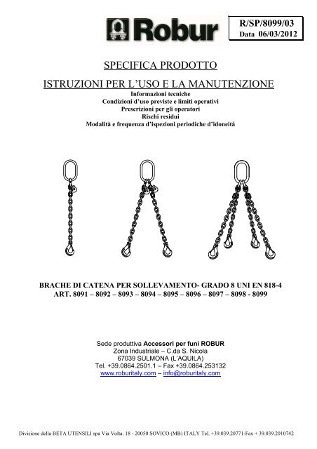
BRACHE DI CATENA PER SOLLEVAMENTO- GRADO 8 UNI EN 818-4<br />
ART. 8091 – 8092 – 8093 – 8094 – 8095 – 8096 – 8097 – 8098 - 8099<br />
Sede produttiva Accessori <strong>per</strong> funi ROBUR<br />
Zona Industriale – C.da S. Nico<strong>la</strong><br />
67039 SULMONA (L’AQUILA)<br />
Tel. +39.0864.2501.1 – Fax +39.0864.253132<br />
www.roburitaly.com – info@roburitaly.com<br />
Divisione del<strong>la</strong> BETA UTENSILI spa Via Volta. 18 - 20050 SOVICO (MB) ITALY Tel. +39.039.20771-Fax + 39.039.2010742
1) CARATTERISTICHE TECNICHE DELL’ACCESSORIO<br />
Composizione del<strong>la</strong> braca<br />
ad alta resistenza:<br />
Norme di riferimento:<br />
Trattamento su<strong>per</strong>ficiale:<br />
Campanel<strong>la</strong>¹ art. 8085<br />
Campanel<strong>la</strong> trip<strong>la</strong>² art. 8086<br />
Maglia di giunzione art. 8090<br />
Gancio Clevis<br />
art.8060<br />
Gancio Clevis autobloccante³ art. 8058<br />
Gancio accorciatore ad occhio art. 8061<br />
Catena art. 8100<br />
¹ <strong>per</strong> braca a 1 e 2 bracci ² <strong>per</strong> braca a 3 e 4 bracci ³ in alternativa<br />
Catena UNI EN 818-2<br />
Campanel<strong>la</strong> UNI EN 1677-4<br />
Campanel<strong>la</strong> trip<strong>la</strong> UNI EN 1677-4<br />
Componenti UNI EN 1677-1<br />
Gancio Clevis UNI EN 1677-2<br />
Ganci Clevis autobloccante UNI EN 1677-3<br />
Verniciatura epossidica e/o protezione antiruggine<br />
Il col<strong>la</strong>udo viene eseguito in base a specifiche e regole interne in riferimento al<strong>la</strong><br />
norma UNI EN ISO 9001.<br />
L’articolo è conforme al<strong>la</strong> Direttiva Macchine 2006/42/CE<br />
Divisione del<strong>la</strong> BETA UTENSILI spa Via Volta. 18 - 20050 SOVICO (MB) ITALY Tel. +39.039.20771-Fax + 39.039.2010742
CARATTERISTICHE DIMENSIONALI:<br />
TABELLA “A”<br />
(WLL) Carichi massimi di esercizio in t, <strong>per</strong><br />
Dimensioni<br />
nominali del<strong>la</strong><br />
braca<br />
Ø D<br />
Brache a<br />
braccio singolo<br />
Brache a due bracci<br />
Brache a tre e a quattro bracci<br />
0°
Definizioni:<br />
• Braca di catena: Insieme costituito da catena o catene, unite ad accessori di estremità su<strong>per</strong>iori ed<br />
inferiori, conformi ai requisiti al<strong>la</strong> norma europea UNI EN 818-4, <strong>per</strong> collegare carichi al gancio di<br />
una gru o di qualsiasi altro apparecchio di sollevamento.<br />
• Carico massimo di esercizio (WLL) di una braca di catena: La massa che al massimo <strong>la</strong> braca<br />
è autorizzata a sostenere nel normale servizio di sollevamento.<br />
• Carico di rottura: è il carico massimo che l’articolo può sopportare durante una prova di trazione,<br />
al termine del<strong>la</strong> quale non è più utilizzabile.<br />
• Coefficiente di sicurezza: è il rapporto tra il carico di rottura minimo garantito e il carico<br />
massimo di esercizio. Nell’articolo in oggetto è 4.<br />
• Ispezione: Controllo visivo re<strong>la</strong>tivo allo stato del<strong>la</strong> braca di catena <strong>per</strong> individuare evidenti<br />
danneggiamenti o usure che possono alterarne l’utilizzo.<br />
• Esame accurato: Esame visivo effettuato da una <strong>per</strong>sona competente e, se necessario, coadiuvato<br />
da altri mezzi, quali i controlli non-distruttivi, al fine di individuare danneggiamenti o usure che<br />
possono alterare l’utilizzo del<strong>la</strong> braca di catena.<br />
• Persona competente: Persona designata, istruita correttamente, qualificata <strong>per</strong> conoscenza e<br />
es<strong>per</strong>ienza pratica; che ha ricevuto le <strong>istruzioni</strong> necessarie <strong>per</strong> seguire le prove e gli esami richiesti.<br />
2) SPECIFICHE DI COLLAUDO<br />
Ogni singolo elemento che compone <strong>la</strong> braca è conforme alle prescrizioni stabilite dalle seguenti<br />
norme:<br />
2.A Catena<br />
UNI EN 818-2<br />
2.B Dispositivi di giunzione meccanica<br />
UNI EN 1677-1<br />
2.C Campanelle e campanelle triple<br />
UNI EN 1677-4<br />
2.D Ganci di sollevamento<br />
UNI EN 1677-2<br />
2.E Ganci di sollevamento con chiusura autobloccanti<br />
UNI EN 1677-3<br />
Divisione del<strong>la</strong> BETA UTENSILI spa Via Volta. 18 - 20050 SOVICO (MB) ITALY Tel. +39.039.20771-Fax + 39.039.2010742
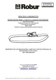
3) COME LEGGERE LA MARCATURA:<br />
Sul<strong>la</strong> braca di catena è apposta una targa riportante maniera indelebile, marcature e sigle che<br />
identificano il <strong>prodotto</strong> e definiscono le caratteristiche e le applicazioni.<br />
Braca ad un braccio<br />
1) Numero in codice rappresentante <strong>la</strong> dimensione<br />
nominale del<strong>la</strong> catena<br />
2) Numero dei bracci<br />
3) Marchio d’identificazione individuale<br />
4) Simbolo del fabbricante<br />
5) Marchio CE<br />
6) Carico massimo di esercizio<br />
Braca a due bracci<br />
1) Numero in codice rappresentante <strong>la</strong> dimensione<br />
nominale del<strong>la</strong> catena<br />
2) Numero dei bracci<br />
3) Marchio d’identificazione individuale<br />
4) Simbolo del fabbricante<br />
5) Marchio CE<br />
6) Carico massimo di esercizio a 45°<br />
7) Carico massimo di esercizio a 60°<br />
Divisione del<strong>la</strong> BETA UTENSILI spa Via Volta. 18 - 20050 SOVICO (MB) ITALY Tel. +39.039.20771-Fax + 39.039.2010742
4) AVVERTENZE GENERALI.<br />
Con riferimento a quanto riportato in queste <strong>istruzioni</strong> d’uso <strong>la</strong> BETA UTENSILI S.P.A. declina ogni<br />
responsabilità in caso di:<br />
• Uso degli accessori contrario alle leggi nazionali sul<strong>la</strong> sicurezza e<br />
sull’antinfortunistica.<br />
• Errata scelta o predisposizione dell’apparecchio di sollevamento con il quale saranno<br />
connessi.<br />
• Mancata o errata osservanza delle <strong>istruzioni</strong> <strong>per</strong> l’uso.<br />
• Modifiche agli accessori.<br />
• Uso improprio e omessa <strong>manutenzione</strong> ordinaria.<br />
• Uso combinato ad accessori non conformi.<br />
!ATTENZIONE: I dati di marcatura non devono essere rimossi con mo<strong>la</strong>ture o abrasioni,<br />
(neanche accidentali, le braghe senza riferimenti di identificazione devono essere rese<br />
inutilizzabili e rottamate).<br />
Non è consentito apporre caratteri aggiuntivi a quelli di fabbricazione.<br />
5) CRITERI DI SCELTA<br />
I parametri che devono essere attentamente considerati nel<strong>la</strong> scelta del<strong>la</strong> braca sono:<br />
5.A IL CARICO MASSIMO DI ESERCIZIO<br />
Il peso del carico da sollevare deve essere inferiore o uguale al valore del carico massimo di<br />
esercizio (WLL) previsto <strong>per</strong> <strong>la</strong> braca presa in considerazione, stampato sul <strong>prodotto</strong> e riportato nel<strong>la</strong><br />
tabel<strong>la</strong> “A”.<br />
Nel sollevamento con brache a più bracci il carico di utilizzazione deve essere stabilito in conformità<br />
al<strong>la</strong> tabel<strong>la</strong> “A” solo <strong>per</strong> carichi distribuiti simmetricamente.<br />
Attenzione: l’angolo di ciascun braccio non deve mai su<strong>per</strong>are 60° rispetto al<strong>la</strong> verticale.<br />
MAX 60°<br />
Divisione del<strong>la</strong> BETA UTENSILI spa Via Volta. 18 - 20050 SOVICO (MB) ITALY Tel. +39.039.20771-Fax + 39.039.2010742
5.B ELEMENTO DI ACCOPPIAMENTO<br />
Assicurarsi che l’elemento di accoppiamento sia adeguato alle caratteristiche di portata del<strong>la</strong> braca,<br />
abbia adeguato spessore, composizione chimica e garantisca una resistenza meccanica sufficiente al<strong>la</strong><br />
trazione esercitata dal<strong>la</strong> presa.<br />
5.C TEMPERATURE D’IMPIEGO<br />
L’intervallo di tem<strong>per</strong>atura in cui è consentito l’impiego del<strong>la</strong> braca va da –40°C a +200°C.<br />
In caso di utilizzo a tem<strong>per</strong>ature su<strong>per</strong>iori ridurre il carico in <strong>per</strong>centuale come da tabel<strong>la</strong> seguente.<br />
Variazione del carico massimo di esercizio con <strong>la</strong> tem<strong>per</strong>atura<br />
Tem<strong>per</strong>atura t °C<br />
-40
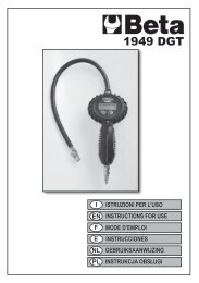
8) MOVIMENTAZIONE DEL CARICO<br />
Collegare <strong>la</strong> braca al carico da sollevare in funzione del suo centro di gravità, in partico<strong>la</strong>re:<br />
• Per le brache a braccio singolo, il punto di aggancio deve essere situato sul<strong>la</strong> verticale sopra il<br />
centro di gravità.<br />
• Per le brache a due bracci, i punti di aggancio devono essere situati in posizione opposta tra<br />
loro, e al di sopra del centro di gravità.<br />
• Per le brache di catena a tre o quattro bracci, i punti di aggancio devono essere distribuiti in<br />
un piano attorno al centro di gravità, <strong>la</strong> loro distribuzione deve essere uniforme e devono<br />
stare al di sopra del centro di gravità fig. 1.<br />
Fig. 1<br />
I valori di carico massimo di esercizio sono stati determinati ipotizzando che il carico del<strong>la</strong> braca sia<br />
simmetrico. Ciò significa che quando il carico è sollevato, i bracci del<strong>la</strong> braca sono simmetricamente<br />
disposti in un piano, e sottendono angoli uguali rispetto al<strong>la</strong> verticale (fig 1)<br />
Quando si usano brache a due, tre, e quattro bracci, i punti di aggancio e <strong>la</strong> configurazione del<strong>la</strong> braca<br />
devono essere scelti in modo che gli angoli fra i bracci del<strong>la</strong> braca e <strong>la</strong> verticale stiano nell’intervallo<br />
marcato sul<strong>la</strong> braca (0°÷60°).<br />
Tutti gli angoli rispetto al<strong>la</strong> verticale (l’angolo β nel<strong>la</strong> figura 1) devono essere uguali.<br />
Angoli con <strong>la</strong> verticale minori di 15° devono essere evitati, <strong>per</strong>ché generano un rischio elevato di<br />
squilibrio del carico.<br />
Simmetria del carico<br />
Nel caso di brache a tre bracci, se i bracci non sono simmetricamente disposti nel piano, vi sarà una<br />
tensione più grande nel braccio in cui <strong>la</strong> somma degli angoli piani rispetto ai bracci adiacenti è più<br />
elevata. Si ha medesimo risultato nelle brache a quattro bracci, con l’eccezione che occorrerebbe<br />
mettere in conto anche <strong>la</strong> rigidità del carico; se il carico è rigido può avvenire che <strong>la</strong> maggioranza<br />
del<strong>la</strong> massa sia sopportata so<strong>la</strong>mente da tre o anche due bracci, mentre i rimanenti bracci servono<br />
solo ad equilibrare il carico (vedere figura 2).<br />
Nel caso di brache a due, tre o quattro bracci, se i bracci formano angoli differenti rispetto al<strong>la</strong><br />
verticale <strong>la</strong> tensione maggiore sarà nel braccio che forma con <strong>la</strong> verticale l’angolo più piccolo.<br />
In casi estremi, se un braccio è verticale può sopportare tutto il carico (vedere figura 2).<br />
Se vi è contemporaneamente <strong>per</strong>dita di simmetria nel piano e disuguaglianza di angoli rispetto al<strong>la</strong><br />
verticale, i due effetti si cumuleranno, sommandosi o sottraendosi l’un l’altro (vedere figura 2).<br />
Si può assumere che il carico sia simmetrico, se sono soddisfatte tutte le seguenti condizioni:<br />
Divisione del<strong>la</strong> BETA UTENSILI spa Via Volta. 18 - 20050 SOVICO (MB) ITALY Tel. +39.039.20771-Fax + 39.039.2010742
a) Il carico è meno dell’80% del WLL marcato;<br />
b) Tutti gli angoli dei bracci del<strong>la</strong> braca di catena, rispetto al<strong>la</strong> verticale, non sono minori di 15°;<br />
c) Tutti gli angoli dei bracci del<strong>la</strong> braca, rispetto al<strong>la</strong> verticale, sono compresi in un arco di 15°,<br />
l’uno rispetto all’altro;<br />
d) Nel caso di brache a tre o quattro bracci, gli angoli piani sono compresi in un arco di 15°,<br />
l’uno rispetto all’altro.<br />
Se le condizioni sopra descritte non sono contemporaneamente soddisfatte, il carico deve essere<br />
considerato asimmetrico e il sollevamento affidato a una <strong>per</strong>sona competente <strong>per</strong> stabilire il<br />
carico di sicurezza del<strong>la</strong> braca. Alternativamente, in caso di carico asimmetrico il carico<br />
massimo di sollevamento del<strong>la</strong> braca deve essere assunto pari al<strong>la</strong> metà del WLL marcato.<br />
Se il carico tende a inclinarsi, ripristinare le giuste condizioni di sollevamento accorciando alcuni dei<br />
bracci del<strong>la</strong> braca, utilizzando gli appositi ganci accorciatori.<br />
1) Centro di gravità<br />
2) Forte tensione in questo braccio<br />
3) Carico<br />
Fig. 2 (figura carico asimmetrico)<br />
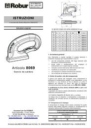
Tutte le brache con più bracci generano una componente di forza orizzontale (vedere figura 3)<br />
Che aumenta con l’aumentare dell’angolo fra i bracci stessi.<br />
Ove i ganci o altri fissaggi sono infi<strong>la</strong>ti in una catena avvolta ad anello, come ad esempio attorno a<br />
una cassa o ad un fusto, <strong>la</strong> componente orizzontale del<strong>la</strong> forza è assai più grande e conseguentemente<br />
l’angolo di tali bracci non deve su<strong>per</strong>are i 30° rispetto al<strong>la</strong> verticale.<br />
Occorre sempre prestare attenzione che il carico da spostare sia in grado di resistere alle componenti<br />
orizzontali del<strong>la</strong> forza senza essere danneggiato.<br />
E’ bene che il gancio al quale è attaccata <strong>la</strong> braca sia situato direttamente sopra il centro di gravità.<br />
Nel<strong>la</strong> figura 3 sono indicate le variazioni del<strong>la</strong> forza sui bracci di una braca <strong>per</strong> effetto dell’angolo <strong>per</strong><br />
un carico di 10t.<br />
Divisione del<strong>la</strong> BETA UTENSILI spa Via Volta. 18 - 20050 SOVICO (MB) ITALY Tel. +39.039.20771-Fax + 39.039.2010742
Legenda<br />
1) Forza sui bracci<br />
2) Componente orizzontale del<strong>la</strong> forza<br />
3) Carico di 10t<br />
Fig. 3<br />
L’area tratteggiata indica angoli maggiori di 60° rispetto al<strong>la</strong> verticale, con i quali le brache di<br />
catena non devono essere mai usate.<br />
Metodo di connessione<br />
Durante il collegamento tra apparecchio di sollevamento e carico prestare attenzione al<strong>la</strong> posizione<br />
del<strong>la</strong> catena, <strong>la</strong> quale non deve presentare né nodi, né torsioni. Il punto di sollevamento deve essere<br />
assestato bene sul fondo del gancio e mai poggiato sul<strong>la</strong> punta o sul becco; il gancio deve essere<br />
libero di inclinarsi in qualsiasi direzione, <strong>per</strong> evitare flessioni.<br />
Per <strong>la</strong> medesima ragione <strong>la</strong> campanel<strong>la</strong> principale deve essere libera di inclinarsi in ogni direzione<br />
rispetto al gancio al quale è connessa.<br />
Quando vengono utilizzati un numero di bracci inferiore al totale, ridurre il carico rispetto al WLL<br />
marcato sul<strong>la</strong> braca, applicando i fattori indicati nel<strong>la</strong> tabel<strong>la</strong> seguente.<br />
Tipi di braca<br />
Numero di bracci utilizzati<br />
Fattore da applicare al WLL<br />
marcato<br />
Due bracci 1 1/2<br />
Tre o quattro bracci 2 2/3<br />
Tre o quattro bracci 1 1/3<br />
Divisione del<strong>la</strong> BETA UTENSILI spa Via Volta. 18 - 20050 SOVICO (MB) ITALY Tel. +39.039.20771-Fax + 39.039.2010742
Uso dell’accessorio presa e manovra<br />
Prestare sempre <strong>la</strong> massima attenzione a ogni specifico avvertimento <strong>per</strong> <strong>la</strong> movimentazione del<br />
carico. Prima di azionare il sollevatore, assicurarsi che il carico sia libero di muoversi e non sia<br />
bloccato da elementi di collegamento o da altri impedimenti.<br />
Mettere in tiro le catene prima di sollevare.<br />
Stare lontani con le mani o altre parti del corpo quando le catene sono poste in tensione.<br />
Il carico va sollevato lentamente, va control<strong>la</strong>to che sia sicuro e che assuma <strong>la</strong> posizione preventivata.<br />
Muovere il carico con movimenti lenti, lineari e costanti, evitando brusche accelerate o frenate che,<br />
<strong>per</strong> effetto dell’inerzia, possono creare <strong>per</strong>icolose oscil<strong>la</strong>zioni.<br />
Predisporre anticipatamente il luogo di deposito al suolo del carico, assicurandosi che il terreno (o il<br />
pavimento) sia adeguatamente resistente <strong>per</strong> sopportare il carico.<br />
Assicurarsi che l’accesso al luogo di deposito sia privo di ostacoli e che le <strong>per</strong>sone siano a distanza di<br />
sicurezza.<br />
Il carico deve essere appoggiato con caute<strong>la</strong> facendo attenzione che <strong>la</strong> braca non si impigli.<br />
Prima di allentare le catene control<strong>la</strong>re che il carico sia ben supportato e stabile.<br />
Una volta che il carico è appoggiato in sicurezza, <strong>la</strong> braca deve essere rimossa a mano, e mai<br />
allontanata con l’apparecchio di sollevamento.<br />
Questo documento prevede solo l’utilizzo del<strong>la</strong> braca con ganci collegati ad appositi organi di<br />
presa,(golfari,grilli ecc..).<br />
9) CONTROINDICAZIONI D’USO<br />
L’utilizzo delle brache <strong>per</strong> scopi non previsti, il suo uso in condizioni estremamente <strong>per</strong>icolose, <strong>la</strong><br />
carenza di <strong>manutenzione</strong>, possono comportare gravi situazioni di <strong>per</strong>icolo <strong>per</strong> l’incolumità delle<br />
<strong>per</strong>sone esposte e di danno <strong>per</strong> l’ambiente di <strong>la</strong>voro, oltre che pregiudicare <strong>la</strong> funzionalità e <strong>la</strong><br />
sicurezza effettiva del <strong>prodotto</strong>. Le azioni di seguito citate che ovviamente non possono coprire<br />
l’intero arco di potenziali possibilità di “cattivo uso” dell’accessorio, costituiscono tuttavia quelle<br />
“ragionevolmente” più prevedibili. Quindi:<br />
• NON Utilizzare le brache collegandole ad apparecchiature di dimensioni, tem<strong>per</strong>atura,<br />
punto d’aggancio e forma non idonei alle sue caratteristiche.<br />
• NON sollevare il carico sottoponendo le brache a sollecitazioni di tipo dinamico.<br />
• NON fare oscil<strong>la</strong>re il carico durante <strong>la</strong> movimentazione.<br />
• NON sollevare e trasportare carichi in volo (aeromobili).<br />
• NON usare le brache <strong>per</strong> trazionare carichi vinco<strong>la</strong>ti.<br />
• NON mettere in tensione apparecchiature che possono cambiare <strong>la</strong> loro configurazione<br />
statica, il loro baricentro o lo stato chimico-fisico.<br />
• NON utilizzare l’accessorio in apparecchiature destinate al trasporto di <strong>per</strong>sone o<br />
animali.<br />
• NON usare le brache <strong>per</strong> trainare carichi vinco<strong>la</strong>ti.<br />
• NON o<strong>per</strong>are in aree dove è prescritto l’uso di componenti antidef<strong>la</strong>granti/antiscintil<strong>la</strong><br />
o in presenza di forti campi magnetici.<br />
• NON saldare sull’accessorio partico<strong>la</strong>ri metallici, ne intervenire con riporti di saldatura<br />
od utilizzarlo come massa <strong>per</strong> saldatrici.<br />
• NON utilizzare in le brache immerse in soluzioni acide o in ambienti con vapori acidi.<br />
• NON decappare o assoggettare le brache a procedimenti galvanici.<br />
Divisione del<strong>la</strong> BETA UTENSILI spa Via Volta. 18 - 20050 SOVICO (MB) ITALY Tel. +39.039.20771-Fax + 39.039.2010742
10) IDONEITA’ ALL’UTILIZZO<br />
L’accessorio è stato sottoposto a col<strong>la</strong>udo presso il costruttore <strong>per</strong> accertare <strong>la</strong> rispondenza funzionale<br />
e prestazionale dello stesso. L’attestato che accompagna <strong>la</strong> fornitura certifica il su<strong>per</strong>amento con esito<br />
positivo dei test di col<strong>la</strong>udo previsti dal<strong>la</strong> norma. L’utilizzatore deve eseguire in ogni caso, prima di<br />
iniziare ad o<strong>per</strong>are <strong>la</strong> verifica del<strong>la</strong> rispondenza funzionale e prestazionale dell’accessorio instal<strong>la</strong>to<br />
<strong>per</strong> confermare l’idoneità all’impiego dell’intera instal<strong>la</strong>zione.<br />
11) ISPEZIONE E MANUTENZIONE<br />
Comprende gli interventi di ispezione e <strong>manutenzione</strong>, eseguiti da <strong>per</strong>sona competente istruita allo<br />
scopo, re<strong>la</strong>tivi a controlli durante l’impiego ed eventuali azioni come previsto nel<strong>la</strong> tabel<strong>la</strong><br />
“interventi di <strong>manutenzione</strong> e controllo”.<br />
L’accessorio deve essere sottoposto ai seguenti controlli:<br />
• VISIVO: verificare l’assenza di difetti su<strong>per</strong>ficiali quali cricche, incisioni, tagli o<br />
fessure, abrasioni.<br />
Controlli sul<strong>la</strong> integrità del<strong>la</strong> marcatura e l’identificazione del<strong>la</strong> braca.<br />
• DEFORMAZIONE: verificare che gli accessori che compongono <strong>la</strong> braca non siano<br />
deformati.<br />
• USURA: verificare che i punti di contatto di tutti i componenti, comprese le maglie<br />
del<strong>la</strong> catena, non siano usurati.<br />
• STATO DI CONSERVAZIONE: verificare l’assenza di ossidazione e corrosione<br />
soprattutto in caso di utilizzo all’a<strong>per</strong>to; verificare l’assenza di cricche con metodi<br />
idonei (es.liquidi penetranti).<br />
Ad intervalli non su<strong>per</strong>iori a dodici mesi occorre eseguire un esame accurato del<strong>la</strong> braca.<br />
Questo intervallo può essere ridotto quando è ritenuto necessario al<strong>la</strong> luce delle condizioni di<br />
utilizzazione.<br />
Le registrazioni di questi esami devono essere conservate <strong>per</strong> l’intera durata del<strong>la</strong> braca.<br />
Le brache devono essere pulite a fondo prima dell’esame, in modo che siano prive di olio, polvere e<br />
ruggine.<br />
Ogni metodo di pulitura che non danneggi il metallo di base è accettabile.<br />
Sono da evitare i metodi che impiegano acidi, surriscaldamenti, rimozioni di metallo o<br />
schiacciamenti di metallo suscettibili a nascondere fessurazioni e difetti su<strong>per</strong>ficiali.<br />
Esaminare <strong>la</strong> braca <strong>per</strong> tutta <strong>la</strong> sua lunghezza predisponendo un’adeguata illuminazione atta ad<br />
individuare qualsiasi usura, deformazione o danneggiamento.<br />
Qui di seguito vi è <strong>la</strong> tabel<strong>la</strong> che riassume le o<strong>per</strong>azioni di <strong>manutenzione</strong> da eseguire e <strong>la</strong> loro<br />
frequenza<br />
Tabel<strong>la</strong> interventi di <strong>manutenzione</strong> e controllo<br />
Tipo di controllo<br />
Controllo visivo gener.<br />
controllo terminali<br />
Deformazione<br />
Usura<br />
controllo accurato<br />
Frequenza intervento<br />
Ad ogni utilizzo Mese Anno<br />
x<br />
x<br />
x<br />
x<br />
x<br />
Nel caso in cui <strong>la</strong> braca sia sottoposta ad un utilizzo gravoso, è necessario effettuare le verifiche di<br />
usura e stato di conservazione con maggiore frequenza.<br />
Divisione del<strong>la</strong> BETA UTENSILI spa Via Volta. 18 - 20050 SOVICO (MB) ITALY Tel. +39.039.20771-Fax + 39.039.2010742
La braca che ha <strong>per</strong>so le sue caratteristiche e di conseguenza l’attitudine all’impiego <strong>per</strong> cui è<br />
stata costruita, deve essere tagliata e demolita, in modo tale che non possa più essere utilizzata.<br />
12) DEMOLIZIONE E ROTTAMAZIONE DELL’ACCESSORIO<br />
L’accessorio deve essere demolito mediante taglio, in modo tale che non possa più essere utilizzato,<br />
sia al termine del<strong>la</strong> vita prevista, che nel caso presenti:<br />
una diminuzione di sezione su<strong>per</strong>iore al 10% nel<strong>la</strong> zona di contatto fra le maglie;<br />
un allungamento del<strong>la</strong> catena rispetto al<strong>la</strong> dimensione iniziale;<br />
una deformazione <strong>per</strong>manente dei componenti rispetto al<strong>la</strong> misura originale;<br />
eventuali cricche, distorsioni o e se si riscontrano riduzioni di sezioni rispetto al<strong>la</strong> misura originale.<br />
Divisione del<strong>la</strong> BETA UTENSILI spa Via Volta. 18 - 20050 SOVICO (MB) ITALY Tel. +39.039.20771-Fax + 39.039.2010742
R/SP-E/8099/03<br />
Date 06/03/2012<br />
PRODUCT SPECIFICATION<br />
OPERATING AND MAINTENANCE INSTRUCTIONS<br />
Technical Specifications<br />
O<strong>per</strong>ating Conditions and Limits<br />
O<strong>per</strong>ator’s Instructions<br />
Residual Risks<br />
How and how often <strong>per</strong>iodical fitness inspections should be conducted<br />
GRADE 8 CHAIN SLINGS – UNI EN 818-4<br />
ITEM 8091 – 8092 – 8093 – 8094 – 8095 – 8096 – 8097 – 8098 - 8099<br />
PRODUCTION SITE<br />
ACCESSORIES FOR WIRE ROPE<br />
ROBUR<br />
Industrial Zone – C.da S. Nico<strong>la</strong><br />
67039 SULMONA (L’AQUILA)<br />
Tel. +39.0864.2501.1 – Fax +39.0864.253132<br />
www.roburitaly.com – info@roburitaly.com<br />
Division of BETA UTENSILI spa Via Volta. 18 - 20050 SOVICO (MB) ITALY Tel. +39.039.20771-Fax + 39.039.2010742
1) TECHNICAL SPECIFICATIONS OF ACCESSORY<br />
Assembling item for Alloy<br />
Chain Slings:<br />
Reference Standards:<br />
SURFACE TREATMENT:<br />
Master links¹ item 8085<br />
Triple Master Link² item 8086<br />
Connecting links item 8090<br />
Clevis hooks item 8060<br />
Self-locking clevis hooks ³ item 8058<br />
Eye grab hooks item 8061<br />
Chain item 8100<br />
¹ for chain slings with 1 or 2 legs ² for chain slings with 3 or 4 legs ³ alternatively<br />
Chain UNI EN 818-2<br />
Master links UNI EN 1677-4<br />
Triple Master Link UNI EN 1677-4<br />
Components UNI EN 1677-1<br />
Clevis hooks UNI EN 1677-2<br />
Self-locking clevis hooks UNI EN 1677-3<br />
Epoxy painting and/or rust protection<br />
The test is <strong>per</strong>formed on the basis of in-house <strong>specifica</strong>tions and rules in accordance with UNI EN<br />
ISO 9001.<br />
The item complies with Machinery Directive 2006/42/EC<br />
Division of BETA UTENSILI spa Via Volta. 18 - 20050 SOVICO (MB) ITALY Tel. +39.039.20771-Fax + 39.039.2010742
DIMENSIONAL SPECIFICATIONS:<br />
TABLE “A”<br />
(WLL) Working load limits in tons, for<br />
Nominal size of<br />
chain sling<br />
Ø D<br />
Single-leg<br />
chain slings<br />
Two-leg chain slings<br />
Three- and four-leg chain slings<br />
0°
Definitions:<br />
• Chain sling: a chain or set of chains joined to up<strong>per</strong> and lower end accessories, complying with<br />
UNI EN 818-4, for connecting any loads to the hook of a crane or any other lifting apparatus.<br />
• Working load limit (WLL) of a chain sling: the maximum mass the chain sling may support<br />
during any standard lifting jobs.<br />
• Breaking force: the maximum load the item can support during a tensile test, after which it can no<br />
longer be used.<br />
• Safety coefficient: guaranteed minimum breaking force to working load limit ratio. The safety<br />
coefficient of the above-mentioned item is 4.<br />
• Inspection: visual testing of the state of the chain sling, to check for clear damage or wear which<br />
may affect its use.<br />
• Accurate examination: visual inspection <strong>per</strong>formed by a trained <strong>per</strong>son, supported, if need be, by<br />
any other instruments, including non-destructive testing, to check for damage or wear which may<br />
affect the use of the chain sling.<br />
• Trained <strong>per</strong>son: a designated, suitably trained <strong>per</strong>son who has pro<strong>per</strong> know-how and practical<br />
ex<strong>per</strong>tise and has been given the instructions needed to <strong>per</strong>form any required tests and<br />
examinations.<br />
2) TESTING SPECIFICATIONS<br />
Every single part of the chain sling meets the requirements under the relevant standards:<br />
2.A Chain<br />
UNI EN 818-2<br />
2.B Mechanical connecting devices<br />
UNI EN 1677-1<br />
2.C Connecting links and master links<br />
UNI EN 1677-4<br />
2.D Eye hooks<br />
UNI EN 1677-2<br />
2.E Self-locking eye hooks<br />
UNI EN 1677-3<br />
Division of BETA UTENSILI spa Via Volta. 18 - 20050 SOVICO (MB) ITALY Tel. +39.039.20771-Fax + 39.039.2010742
3) HOW TO READ MARKINGS:<br />
The chain sling carries a p<strong>la</strong>te containing indelible marks and initials which identify the product and<br />
define the <strong>specifica</strong>tions and applications.<br />
Single-leg chain sling<br />
1) Code number representing nominal size of chain<br />
2) Number of legs<br />
3) Individual identification mark<br />
4) Manufacturer’s symbol<br />
5) CE mark<br />
6) Working load limit<br />
Two-leg chain sling<br />
1) Code number representing nominal size of chain<br />
2) Number of legs<br />
3) Individual identification mark<br />
4) Manufacturer’s symbol<br />
5) CE mark<br />
6) Working load limit at 45°<br />
7) Working load limit at 60°<br />
Division of BETA UTENSILI spa Via Volta. 18 - 20050 SOVICO (MB) ITALY Tel. +39.039.20771-Fax + 39.039.2010742
4) GENERAL WARNINGS<br />
As regards the information provided in these o<strong>per</strong>ating instructions, BETA UTENSILI S.P.A. will<br />
accept no responsibility in the event of:<br />
• any use of the accessories other than the uses under national safety and accident<br />
prevention <strong>la</strong>ws;<br />
• mistaken choice or arrangement of the lifting apparatus they are going to be connected<br />
to;<br />
• failure to comply with, or pro<strong>per</strong>ly follow, the o<strong>per</strong>ating instructions;<br />
• changes to the accessories;<br />
• misuse or failure to carry out routine maintenance jobs;<br />
• use with noncompliant accessories.<br />
!CAUTION: The marking data should not be removed by grinding or abrasion (whether<br />
accidental or not – any chain slings that do not carry any identification references should be<br />
made unusable and scrapped).<br />
No characters other than the manufacturer’s may be affixed.<br />
5) SELECTION CRITERIA<br />
The following parameters should be carefully considered in choosing the chain sling:<br />
5.A WORKING LOAD LIMIT<br />
The weight of the load to lift should be lower than or equal to the working load limit (WLL)<br />
recommended for the chain sling being considered, as printed on the product and shown in table “A”.<br />
When lifting with multiple-leg chain slings, the working load limit should be established in<br />
accordance with table “A” only for symmetrically distributed loads.<br />
Caution: the angle of each leg should never exceed 60° to the vertical line.<br />
MAX 60°<br />
Division of BETA UTENSILI spa Via Volta. 18 - 20050 SOVICO (MB) ITALY Tel. +39.039.20771-Fax + 39.039.2010742
5.B CONNECTING PART<br />
Make sure that the connecting part suits the load capacity of the chain sling, is thick enough, has a<br />
pro<strong>per</strong> chemical composition and an adequate mechanical resistance to traction forces.<br />
5.C OPERATING TEMPERATURES<br />
Tem<strong>per</strong>ature range allowed for the chain sling: –40 °C ÷ +200 °C.<br />
If the chain sling is used at higher tem<strong>per</strong>atures, reduce the load in <strong>per</strong>centage, according to the<br />
following table.<br />
Variation in working load limit as tem<strong>per</strong>ature varies<br />
Tem<strong>per</strong>ature t °C<br />
-40
8) LOAD HANDLING<br />
Connect the chain sling to the load to lift, according to its centre of gravity; in particu<strong>la</strong>r:<br />
• as for single-leg chain slings, the hooking point should lie on the vertical line above the<br />
centre of gravity;<br />
• as for two-leg chain slings, the hooking points should face each other, above the centre of<br />
gravity;<br />
• as for three- or four-leg chain slings, the hooking points should be distributed over a p<strong>la</strong>ne,<br />
round the centre of gravity; they should be distributed uniformly and lie above the centre of<br />
gravity (fig. 1).<br />
Fig. 1<br />
The working load limits were determined by assuming that the chain sling load is asymmetrical.<br />
Hence whenever the load is lifted, the legs of the chain sling are symmetrically arranged in a p<strong>la</strong>ne<br />
and subtend equal angles to the vertical line (fig. 1)<br />
Whenever two-, three- or four-leg chain slings are used, both the hooking points and the<br />
configuration of the chain sling should be so chosen that the angles between the legs of the chain<br />
sling and the vertical line lie within the range as marked on the chain sling (0°÷60°).<br />
All the angles to the vertical line (angle β in figure 1) should be the same.<br />
Any angles to the vertical line smaller than 15° should be avoided, because they result in a high risk<br />
of unba<strong>la</strong>nced loads.<br />
Load Symmetry<br />
As for three-leg chain slings, if the legs are not symmetrically arranged in the p<strong>la</strong>ne, the main tension<br />
will result in the leg where the sum of the p<strong>la</strong>ne angles to the adjacent legs is higher. The same result<br />
will be produced in four-leg chain slings, except that the rigidity of the load should also be<br />
considered; if the load is rigid, most of the mass may be supported by three or even two legs; whereas<br />
the remaining legs are only used to ba<strong>la</strong>nce the load (see figure 2).<br />
As for two-, three- or four-leg chain slings, if the legs form different angles to the vertical line, the<br />
main tension will result in the leg forming the smallest angle to the vertical line.<br />
Under extreme circumstances, a vertical leg can support the whole load (see figure 2).<br />
If any loss of symmetry in the p<strong>la</strong>ne and different angles to the vertical line are shown at the same<br />
time, the two effects will accumu<strong>la</strong>te, being added to or subtracted from each other (see figure 2).<br />
The load can be assumed to be symmetrical if all of the following conditions are satisfied:<br />
Division of BETA UTENSILI spa Via Volta. 18 - 20050 SOVICO (MB) ITALY Tel. +39.039.20771-Fax + 39.039.2010742
a) the load accounts for less than 80% of the marked WLL;<br />
b) none of the angles of the legs of the chain sling to the vertical line are smaller than 15°;<br />
c) all of the angles of the legs of the chain sling to the vertical line lie within 15°, to each other;<br />
d) as for three- or four-leg chain slings, the p<strong>la</strong>ne angles lie within 15°, to each other.<br />
If the above-mentioned conditions are not satisfied simultaneously, the load should be considered<br />
asymmetrical, and the load should be lifted by a trained <strong>per</strong>son, so that the safety load of the chain<br />
sling can be established. Alternatively, if the load is asymmetrical, the working load limit of<br />
the chain sling should be assumed to account for 50% of the marked WLL.<br />
If the load tends to bend over, restore the correct lifting conditions by shortening some of the legs of<br />
the chain sling by means of shortening hooks.<br />
1) Centre of gravity<br />
2) High tension in this leg<br />
3) Load<br />
Fig. 2 (asymmetrical load)<br />
All of the chain slings with more than one leg produce a horizontal component of force (see figure 3),<br />
which increases as the angle between the legs increases.<br />
If the hooks or any other fasteners have been inserted into a ring chain – for example, round a case or<br />
a drum –, the horizontal component of force is much bigger and, consequently, the angle of such legs<br />
should not exceed 30° to the vertical line.<br />
It should be emphasized that the load to shift should be capable of withstanding any horizontal<br />
components of force, while avoiding being damaged.<br />
The hook the chain sling has been fixed to should lie immediately above the centre of gravity.<br />
Figure 3 shows the variations in force on the legs of a chain sling through the angle with a load of 10<br />
tons.<br />
Division of BETA UTENSILI spa Via Volta. 18 - 20050 SOVICO (MB) ITALY Tel. +39.039.20771-Fax + 39.039.2010742
Legend<br />
1) Force on legs<br />
2) Horizontal component of force<br />
3) 10-ton load<br />
Fig. 3<br />
The dashed area shows angles to the vertical line exceeding 60°; no chain slings may be used<br />
with such angles.<br />
CONNECTING METHOD<br />
While connecting the lifting apparatus to the load, make sure that the chain is free from both knots<br />
and twists. The lifting point should be suitably arranged at the bottom of the hook and should not lie<br />
on the tip; the hook should be capable of freely tilting in any direction, to prevent bending.<br />
For the same reason, the main master link shall be capable of freely tilting in any direction compared<br />
to the hook it is connected to.<br />
If not all of the legs are used, reduce the load compared to the WLL marked on the chain sling,<br />
applying the factors reported in the following table.<br />
Chain sling types Number of legs used Factor to apply to marked WLL<br />
Two-leg 1 1/2<br />
Three- or four-leg 2 2/3<br />
Three- or four-leg 1 1/3<br />
Division of BETA UTENSILI spa Via Volta. 18 - 20050 SOVICO (MB) ITALY Tel. +39.039.20771-Fax + 39.039.2010742
Using accessory – grip and handling<br />
Always pay attention to any specific warning when handling the load. Before o<strong>per</strong>ating the lifting<br />
apparatus, make sure that the load is capable of freely moving and is not stopped by any connecting<br />
parts or any other obstacles.<br />
Stretch the chains before lifting the load.<br />
Keep your hands or any other parts of the body away if the chains have been stretched.<br />
The load should be lifted slowly, making sure that it has been fixed firmly and takes the expected<br />
position.<br />
Move the load slowly, linearly and continuously, avoiding sudden acceleration or braking, which may<br />
cause – through inertia – dangerous swinging.<br />
Choose the p<strong>la</strong>ce where to put down the load onto the ground beforehand, making sure that the<br />
ground (or the floor) is capable of supporting the load.<br />
Makes sure that that the p<strong>la</strong>ce where the load is to be put down is free from obstacles and that<br />
everybody is safely distant from it.<br />
The load should be put down cautiously, being careful not to get the chain sling entangled.<br />
Before loosening the chains, make sure that the load is suitably supported and firm.<br />
Once the load has been put down safely, the chain sling should be removed by hand and should never<br />
be removed with the lifting apparatus.<br />
According to this document, the chain sling may only be used with the hooks connected to special<br />
fastening devices (eyebolts, shackles etc.). For any other lifting systems, please contact the<br />
manufacturer.<br />
9) NONPERMISSIBLE USE<br />
Using the chain slings for any purposes other than the purposes they have been designed for, using<br />
them under extremely dangerous conditions and <strong>per</strong>forming poor maintenance may pose a severe<br />
hazard to the safety of the people being exposed and cause severe damage to the working<br />
environment, while affecting the actual serviceability and safety of the product. The precautions<br />
mentioned below, which, obviously enough, cannot cover the whole spectrum of potential “misuses”<br />
of the accessory, should be “reasonably” deemed to be the most common steps to take. Therefore:<br />
• DO NOT connect the chain slings to any apparatus which does not match their<br />
<strong>specifica</strong>tions in terms of size, tem<strong>per</strong>ature, hooking point and shape;<br />
• DO NOT lift the load while subjecting the chain slings to dynamic stress;<br />
• DO NOT let the load swing while handling it;<br />
• DO NOT lift and carry any loads in any aircraft;<br />
• Don’t use the chain slings to pull bounded loads.<br />
• DO NOT stretch any apparatus that may change its static configuration, centre of<br />
gravity or chemical and physical state;<br />
• DO NOT use the accessory in any apparatus designed to carry people or animals;<br />
• DO NOT use the chain slings to pull restrained loads;<br />
• DO NOT work in areas where any explosion/spark-proof parts are expected to be used<br />
or in the presence of big magnetic fields;<br />
• DO NOT weld any metal parts to the accessory; do not use any filling welds; do not use<br />
the accessory as mass for any welder;<br />
• DO NOT use the chain slings immersed in acid solutions or expose them to acid<br />
vapours;<br />
• DO NOT pickle the chain slings or subject them to galvanic processes.<br />
Division of BETA UTENSILI spa Via Volta. 18 - 20050 SOVICO (MB) ITALY Tel. +39.039.20771-Fax + 39.039.2010742
10) FITNESS FOR USE<br />
The accessory was tested for serviceability and <strong>per</strong>formance at the manufacturer’s. The certificate<br />
supplied with it states that the tests under the relevant standards were passed. However, before<br />
starting working, the user should test the installed accessory for serviceability and <strong>per</strong>formance, to<br />
prove the entire system is fit for use.<br />
11) INSPECTION AND MAINTENANCE<br />
Inspections and maintenance jobs should be <strong>per</strong>formed by a trained <strong>per</strong>son, who should check the<br />
accessory during use and take such steps as may be required according to the table “Maintenance<br />
jobs and inspections”.<br />
The accessory should be subjected to the following tests:<br />
• VISUAL TEST: making sure that the accessory is free from surface defects, including<br />
cracks, indentations, cuts, fissures or abrasions.<br />
Making sure that both the marking and the identification information of the chain sling<br />
are intact.<br />
• DEFORMATION TEST: making sure that the accessories of the chain sling have not<br />
got deformed.<br />
• WEAR: making sure that the points of contact of all the component parts, including the<br />
chain links, are not worn.<br />
• STATE OF PRESERVATION: making sure that the accessory is free from oxidation<br />
and corrosion, especially in case of outdoor use; using suitable methods (e.g. liquid<br />
penetrants) to make sure that it is free from cracks.<br />
The chain sling should be accurately inspected at intervals not exceeding twelve months.<br />
This interval may be reduced, depending on the o<strong>per</strong>ating conditions.<br />
The results of the above-mentioned inspections should be stored during the lifetime of the chain<br />
sling.<br />
The chain slings should be thoroughly cleaned before being inspected, so that they can be free from<br />
oil, dust and rust.<br />
Any cleaning method that does not damage basic metal is <strong>per</strong>missible.<br />
Any methods based on the use of acids, overheating, metal removal or metal buckling which may<br />
hide any cracks or surface defects should be avoided.<br />
Examine the chain sling throughout its length, arranging for pro<strong>per</strong> lighting, so that any signs of wear,<br />
deformation or damage can be shown.<br />
The table below deals with the maintenance jobs that should be carried out and their frequency.<br />
Maintenance jobs and inspections<br />
Type of inspection<br />
Frequency<br />
Whenever used Month Year<br />
General visual inspection x<br />
Inspecting terminals<br />
x<br />
Deformation<br />
x<br />
Wear<br />
x<br />
Accurate inspection<br />
x<br />
If the chain sling has been used for heavy-duty jobs, both wear and the state of preservation should be<br />
tested for more frequently.<br />
Division of BETA UTENSILI spa Via Volta. 18 - 20050 SOVICO (MB) ITALY Tel. +39.039.20771-Fax + 39.039.2010742
Any chain sling that has lost its characteristics, its use having thus been affected, should be cut<br />
and scrapped, so that it can no longer be used.<br />
12) SCRAPPING ACCESSORY<br />
The accessory should be scrapped by cutting, so that it can no longer be used, whether at the end of<br />
its expected lifetime or if:<br />
- the section has decreased by more than 10% in the area of contact between the chain links;<br />
- the chain has got longer than it was initially;<br />
- the component parts are <strong>per</strong>manently worn compared to the original size;<br />
- any cracks or distortions are shown, or the sections have decreased compared to the original<br />
sizes.<br />
Division of BETA UTENSILI spa Via Volta. 18 - 20050 SOVICO (MB) ITALY Tel. +39.039.20771-Fax + 39.039.2010742