montageanleitung / installation instructions / instructions de montage ...
montageanleitung / installation instructions / instructions de montage ...
montageanleitung / installation instructions / instructions de montage ...
- No tags were found...

You also want an ePaper? Increase the reach of your titles
YUMPU automatically turns print PDFs into web optimized ePapers that Google loves.
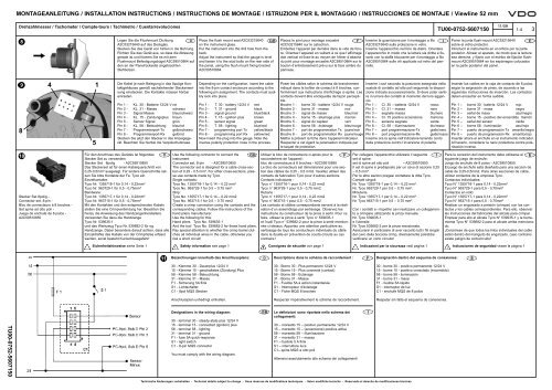
MONTAGEANLEITUNG / INSTALLATION INSTRUCTIONS / INSTRUCTIONS DE MONTAGE / ISTRUZIONI PER IL MONTAGGIO / INSTRUCCIONES DE MONTAJE / Viewline 52 mmDrehzahlmesser / Tachometer / Compte-tours / Tachimetro / Cuentarrevoluciones11/09TU00-0752-5607150 1-4 3Legen Sie die Flushmount Dichtung8DA2C53215640 auf das Deckglas.Stecken Sie das Gerät von hinten in die Bohrung.Richten Sie das Gerät aus, so dass die Ablesunggera<strong>de</strong> ist und fixieren Sie es mit <strong>de</strong>mFlushmount Befestigungsbügel A2C59510864 auf<strong>de</strong>n an <strong>de</strong>r Panelrückseite angebrachtenStehbolzen.Place the flush mount seal A2C53215640 GBon the instrument glass.Put the instrument into the drill hole from theback.Adjust the instrument so that the gauge is leveland fasten it to the stud bolts on the rear si<strong>de</strong> ofthe panel, using the flush mount fixing bracketA2C59510864.Placez le joint pour <strong>montage</strong> encastré FA2C53215640 sur le cabochon.Emboîtez l’appareil par <strong>de</strong>rrière dans le vi<strong>de</strong> <strong>de</strong> forure.Orientez l’appareil en veillant à ce que l’affichagedoit vertical et fixez-le au moyen <strong>de</strong> l’étrier d’attachedu joint pour <strong>montage</strong> encastré A2C59510864 sur leboulon d’entretoisement prévu sur la face arrière dupanneau.Inserire la guarnizione per il montaggio a filo IA2C53215640 sulla protezione in vetro.Inserire l’apparecchio nel foro da dietro. Orientarel’apparecchio in modo che la lettura sia diritta e fissarlocon la staffa bloccante per il montaggio a filoA2C59510864 sulle viti applicate sul retro <strong>de</strong>l pannello.Poner la junta flush-mount A2C53215640 Esobre el vidrio protector.Introducir el instrumento en el orificio por la parteposterior. Alinear el aparato, <strong>de</strong> modo que la lecturasea <strong>de</strong>recha, y fijarlo con el estribo <strong>de</strong> fijación flushmountA2C59510864 en los espárragos colocadosen la parte posterior <strong>de</strong>l panel.9 4851Die Kabel je nach Belegung in das 8polige Kontaktgehäusesgemäß nachstehen<strong>de</strong>r Steckanweisungeinstecken. Die Kontakte müssen hörbareinrasten.Pin 1 - KL. 30 - Batterie 12/24 V rotPin 2 - KL. 31 - Masse schwarzPin 3 - Signal Masse blau/schwarzPin 4 - KL. 15 - Zündungsplus braunPin 5 - Sensor Signal grünPin 6 - KL. 58 - Beleuchtung blau/rotPin 7 - Programmierport-Tx gelb/schwarzPin 8 - Programmierport-Rx gelb/rotStecken Sie jetzt <strong>de</strong>n Stecker in das Anzeigegerät.Beachten Sie hierbei die Verpolschutznase.Depending on the configuration, insert the cableinto the 8-pin contact enclosure according to thefollowing pin assignment. The contacts must audiblylock into place.Pin 1 - T. 30 - battery 12/24 V redPin 2 - T. 31 - ground blackPin 3 - signal ground blue/blackPin 4 - T. 15 - ignition plus brownPin 5 - sensor signal greenPin 6 - T. 58 - lighting blue/redPin 7 - programming port Tx yellow/blackPin 8 - programming port Rx yellow/redNow insert the plug into the gauge. Note theinverse polarity protection nose in the process.Poser les câbles selon le schéma <strong>de</strong> branchementindiqué dans le boîtier <strong>de</strong> contact à 8 broches, conformémentaux <strong>instructions</strong> d’enfichage ci-après. Lescontacts doivent être encliquetés <strong>de</strong> façon perceptible.Broche 1 - borne 30 - batterie 12/24 V rougeBroche 2 - borne 31 - masse noirBroche 3 - signal <strong>de</strong> masse bleu/noirBroche 4 - borne 15 - allumage plus marronBroche 5 - signal du capteur vertBroche 6 - borne 58 - éclairage bleu/rougeBroche 7 - port <strong>de</strong> programmation Tx jaune/noirBroche 8 - port <strong>de</strong> programmation Rx jaune/rougeMettre à présent la fiche dans l’appareil indicateur.Respecter à cet égard la polarisation indiquée parle taquet <strong>de</strong> protection.Inserire i cavi secondo la posizione assegnata nellascatola di contatto ad otto poli seguendo la disposizioneindicata successivamente. Si <strong>de</strong>ve poter sentireil rumore <strong>de</strong>i contatti al momento <strong>de</strong>l loro aggancio.Pin 1 – Cl. 30 – batteria 12/24 V rossoPin 2 – Cl. 31 – massa neroPin 3 – segnale massa blu/neroPin 4 – Cl. 15 positivo accensione marronePin 5 – sensore segnale ver<strong>de</strong>Pin 6 – Cl. 58 – illuminazione blu/rossoPin 7 – port programmazione-Tx giallo/neroPin 8 – port programmazione-Rx giallo/rossoInserire ora la spina nell’indicatore tenendo conto<strong>de</strong>lla protezione contro l’inversione di polarità.Insertar los cables en la caja <strong>de</strong> contacto <strong>de</strong> 8 polos,según la asignación <strong>de</strong> pines, <strong>de</strong> acuerdo a lassiguientes instrucciones <strong>de</strong> inserción. Los contactos<strong>de</strong>ben encastrar en forma audible.Pin 1 – borne 30 - batería 12/24 V rojoPin 2 – borne 31 - masa negroPin 3 – señal <strong>de</strong> masa azul/negroPin 4 – borne 15 - positivo <strong>de</strong>l encendido marrónPin 5 – señal <strong>de</strong>l sensor ver<strong>de</strong>Pin 6 – borne 58 - iluminación azul/rojoPin 7 – puerto <strong>de</strong> programación Tx amarillo/negroPin 8 – puerto <strong>de</strong> programación Rx amarillo/rojoInsertar ahora el enchufe en el instrumento indicador.Al hacerlo, consi<strong>de</strong>rar la nariz protectora contra polarizacióninversa.10Stecker Set 8polig -Connector set, 8-pin -Bloc <strong>de</strong> connecteurs à 8 broches -Set spina ad otto poli -Juego <strong>de</strong> enchufe <strong>de</strong> 8 polos -A2C59510850Für <strong>de</strong>n Anschluss <strong>de</strong>s Gerätes ist folgen<strong>de</strong>s D Use the following connector to connect theStecker Set zu verwen<strong>de</strong>n:instrument:GBStecker Set 8polig - A2C59510850Connector set, 8-pin - A2C59510850Das Steckerset ist für einen Kabelquerschnitt von0,25-0,5mm² ausgelegt. Für an<strong>de</strong>re Querschnitte setzenSie bitte Kontakte <strong>de</strong>r Fa. Tyco ein.Einzelkontakte:Tyco Nr. 1355718-1 für 0,14 - 0,22mm²Tyco Nr. 963729-1 für 0,5 - 0,75mm²Bandware:Tyco Nr. 1355717-1 für 0,14 - 0,22mm²Tyco Nr. 963715-1 für 0,5 - 0,75mm²Mit <strong>de</strong>n Kontakten und <strong>de</strong>n entsprechen<strong>de</strong>n Kabelnstellen Sie eine Crimpverbindung her. Beachten Siehierzu die Anweisung <strong>de</strong>s Handzangenherstellers.Verwen<strong>de</strong>n Sie dazu die HandzangeTyco Nr. 539635-1und das Werkzeug Tyco Nr. 539682-2 für og.Handzange. Dabei beson<strong>de</strong>rs darauf achten, dass alleEinzeldrähte <strong>de</strong>s Kabels von <strong>de</strong>r Crimphülse erfasstwer<strong>de</strong>n, sonst besteht Kurzschlussgefahr!The connector set is <strong>de</strong>signed for a cable cross-sectionof 0.25 - 0.5 mm². For other cross-sections, pleaseuse contacts ma<strong>de</strong> by Tyco.Single contacts:Tyco No. 1355718-1 for 0.14 – 0.22 mm²Tyco No. 963729-1 for 0.5 – 0.75 mm²Strip:Tyco No. 1355717-1 for 0.14 – 0.22 mm2Tyco No. 963715-1 for 0.5 – 0.75 mm2Create a crimp connection using the contacts and thecorresponding cables. Follow the <strong>instructions</strong> of thehand pliers manufacturer.Use the following for this:Hand pliers Tyco No. 539635-1And the tool Tyco No. 539682-2 for these hand pliers.Pay special attention to whether the crimp barrel clutchesall individual wires in the cable, otherwise yourisk a short circuit!Utiliser le bloc <strong>de</strong> connecteurs ci-après pour le Fraccor<strong>de</strong>ment <strong>de</strong> l’appareil :bloc <strong>de</strong> connecteurs à 8 broches - A2C59510850Le bloc <strong>de</strong> connecteurs est dimensionné pour une section<strong>de</strong>s câbles <strong>de</strong> 0,25 - 0,5 mm2. Veuillez utiliser <strong>de</strong>scontacts <strong>de</strong> fabrication Tyco pour d’autres sections.Contacts individuels :Tyco n° 1355718-1 pour 0,14 - 0,22 mm2Tyco n° 963729-1 pour 0,5 - 0,75 mm2Rubans :Tyco n° 1355717-1 pour 0,14 - 0,22 mm2Tyco n° 963715-1 pour 0,5 - 0,75 mm2Les contacts et câbles correspondants servent à la réalisationd’un assemblage par sertissage. Observez les<strong>instructions</strong> du constructeur <strong>de</strong> la pince à sertir. Pour cefaire, utilisez la pince à sertir Tyco n° 539635-1et l’outil Tyco n° 539682-2 pour la pince à sertir mentionnéeci-<strong>de</strong>ssus. Apportez une attention particulière ausertissage <strong>de</strong> tous les conducteurs individuels du câbledans la douille en prévention <strong>de</strong> courts-circuits au cascontraire !Per collegare l’apparecchio utilizzare il seguente Iset di spine:set di spine ad otto poli – A2C59510850Il set di spine è predisposto per un cavo di sezione 0,25– 0,5 mm².Per le altre sezioni pregasi contattare la ditta Tyco.Contatti singoli:Nr. Tyco 1355718-1 per 0,14 – 0,22 mm².Nr. Tyco 963729-1 per 0,5 – 0,75 mm².MinuteriaNr. Tyco 1355717-1 per 0,14 – 0,22 mm².Nr. Tyco 963715-1 per 0,5 – 0,75 mm².Con i contatti e i rispettivi cavi realizzare un collegamentoa crimpare utilizzando la pinza manualeNr. Tyco 539635-1e l’utensileNr. Tyco 539682-2 per la pinza menzionata.Assicurarsi in particolare di aver raccolto tutti i fili singoli<strong>de</strong>l cavo <strong>de</strong>lla boccola crimp, diversamente potrebbeverificarsi un corto circuito!Para la conexión <strong>de</strong>l instrumento <strong>de</strong>be utilizarse el Esiguiente juego <strong>de</strong> enchufe:Juego <strong>de</strong> enchufe <strong>de</strong> 8 polos - A2C59510850.El juego <strong>de</strong> enchufe está diseñado para una sección <strong>de</strong>cable <strong>de</strong> 0,25-0,5mm2. Para otras secciones <strong>de</strong> cable,utilizar contactos <strong>de</strong> la empresa Tyco.Contactos individuales:Tyco N° 1355718-1 para 0,14 - 0,22mm²Tyco N° 963729-1 para 0,5 - 0,75mm²Contactos en rollo:Tyco N° 1355717-1 para 0,14 - 0,22mm²Tyco N° 963715-1 para 0,5 - 0,75mm²Realizar un engarzado a presión (crimpar) con los contactosy los cables correspondientes. Para ello, observarlas instrucciones <strong>de</strong>l fabricante <strong>de</strong>l alicate para crimpar.Emplear para ello el alicate Tyco N° 539635-1 y la herramientaTyco N° 539682-2 para el alicate arriba mencionado.¡Cerciórese <strong>de</strong> que todos los hilos individuales <strong>de</strong>l cableestén <strong>de</strong>ntro <strong>de</strong>l manguito <strong>de</strong> engarzado, caso contrarioexiste peligro <strong>de</strong> cortocircuito!Sicherheitshinweise siehe Seite 1 Safety information see page 1 Consignes <strong>de</strong> sécurité voir page 1 Indicazioni per la sicurezza vedi pagina 1 Indicaciones <strong>de</strong> seguridad véase la página 111Bezeichnungen innerhalb <strong>de</strong>s Anschlussplans:DDescriptions dans le schéma <strong>de</strong> raccor<strong>de</strong>ment :FDesignación <strong>de</strong>ntro <strong>de</strong>l esquema <strong>de</strong> conexiones:E30 - Klemme 30 - Dauerplus 12/24 V15 - Klemme 15 - geschaltetes (Zündung) Plus58 - Klemme 58 - Beleuchtung31 - Klemme 31 - MasseF1 - Sicherung 5A flinkS1 - LichtschalterC1 - 8pol MQS Stecker30 - Borne 30 - Plus permanent 12/24 V15 - Borne 15 - Plus connecté (contact)58 - Borne 58 - Eclairage31 - Borne 31 - MasseF1 - Fusible 5A à action instantanéeS1 - Interrupteur d’éclairageC1 - Fiche MQS 8 broches30 - borne 30 - positivo permanente 12/24 V15 - borne 15 - positivo conectado (encendido)58 - borne 58 - iluminación31 - borne 31 - masaF1 - fusible 5A rápidoS1 - interruptor <strong>de</strong> luzC1 - enchufe MQS <strong>de</strong> 8 polosAnschlussplan unbedingt einhalten.Respecter impérativement le schéma <strong>de</strong> raccor<strong>de</strong>ment.Respetar sin falta el esquema <strong>de</strong> conexiones.TU00-0752-5607150Designations in the wiring diagram:30 - terminal 30 - steady-state plus 12/24 V15 - terminal 15 - connected (ignition) plus58 - terminal 58 - lighting31 - terminal 31 - groundF1 - fuse 5A quick-responseS1 - light switchC1 - 8-pin MQS connectorYou must comply with the wiring diagram.GBLe <strong>de</strong>finizioni sono riportate nello schema <strong>de</strong>icollegamenti:30 – morsetto 15 – positivo permanente 12/24 V15 – morsetto 15 – (accensione) positiva attiva58 – morsetto 58 – illuminazione31 – morsetto 31 – massaF1 – fusibile 5 A flinkS1 – interruttore luceC1– spina MQS a otto poliAttenersi assolutamente allo schema <strong>de</strong>i collegamentiITechnische Än<strong>de</strong>rungen vorbehalten - Technical <strong>de</strong>tails subject to change - Sous réserves <strong>de</strong> modifications techniques - Salvo modifiche tecniche - Reservado el <strong>de</strong>recho <strong>de</strong> modificaciones técnicas