Viewline Marine Catalogue - Howard Instruments
Viewline Marine Catalogue - Howard Instruments
Viewline Marine Catalogue - Howard Instruments

You also want an ePaper? Increase the reach of your titles
YUMPU automatically turns print PDFs into web optimized ePapers that Google loves.
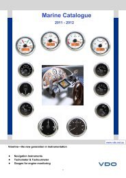
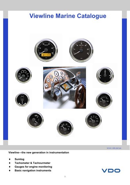
<strong>Viewline</strong> <strong>Marine</strong> <strong>Catalogue</strong><br />
www.vdo.net.au<br />
<strong>Viewline</strong>—the new generation in instrumentation<br />
♦<br />
♦<br />
♦<br />
♦<br />
Sumlog<br />
Tachometer & Tachourmeter<br />
Gauges for engine monitoring<br />
Basic navigation instruments<br />
1
Index<br />
Description Function Diameter Page #<br />
Sumlog Speedometer 50Kn 80/85mm 4<br />
Tachourmeter Tachourmeter 3000, 4000, 5000, 6000 RPM 80/85mm 4<br />
Tachometer Tachometer 3000, 4000, 6000 RPM 80/85/52mm 5<br />
Synchroniser + / - 500 RPM 80/85mm 6<br />
Temp Gauge Water, Oil, Transmission 52mm 7<br />
Pyrometer Exhaust Temp 100ºC to 900ºC 52mm 8<br />
Temp Gauge Outside Air Temp -25º to +50ºC 52mm 9<br />
Pressure Gauge Turbo, Oil, Transmission 52mm 9-1<br />
Fuel Level Gauge Float Arm Type 52mm 12<br />
Fuel Level Gauge Reed Switch Type 13<br />
Fuel Level Gauge Tubular Type 52mm 14<br />
Fresh Water Level Gauge 4-20 mA and Reed Switch Type 52mm 15<br />
Waste/Grey Water Gauge 4-20 mA 52mm 15<br />
Voltmeter Battery Voltage 52mm 16<br />
Ammeter Ampere Meter 60 A and +150 A 52mm 16<br />
Trim Gauge Outboard Engine Trim 52mm 17<br />
Rudder Angle Gauge Rudder Position 52/80/85mm 17<br />
Clock Real Time Clock 52mm 17<br />
Hourmeter Engine Hours 52mm 18<br />
Conversion Table Oceanline to <strong>Viewline</strong> Gauges 19 -21<br />
Electrical Diagrams Gauges connection (power and signals) 22 - 27<br />
Fitting Instructions Conventional & flash mount fittings 28 – 33<br />
Calibration Instructions Speedo, Tachourmeter & Tachometer 34 - 36<br />
Notes 37<br />
3
Sumlog & Tachourmeter<br />
Sumlog<br />
Part Number<br />
Colour<br />
Dial/ Bezel<br />
Ø 80/85 mm<br />
Range Voltage Smart<br />
Transducer<br />
A2C59512404 Black 0 - 12 Kn 12/24V<br />
See below<br />
A2C59512407 White 0 - 12 Kn 12/24V<br />
See below<br />
A2C59512405 Black 0 - 50 Kn 12/24V<br />
See below<br />
A2C59512408 White 0 - 50 Kn 12/24V<br />
See below<br />
Speed<br />
Total & Trip Distance<br />
Depth<br />
Sea Water Temperature<br />
Clock<br />
Voltmeter<br />
External Trip-reset Button<br />
External Mode Button<br />
Through-Hull Kit<br />
Transom Kit<br />
Transducer : Speed - Depth - Sea Water Temp<br />
Part Number Range Mounting Cable Connector<br />
Length<br />
Blue NMEA0183 +<br />
1501120004 12 Kn Transom Kit 10 m<br />
White NMEA0183 -<br />
Red + 12/24V<br />
Black/Shield Negative<br />
Blue NMEA0183 +<br />
X11719000053 50 Kn Transom Kit 10 m<br />
White NMEA0183 -<br />
Red + 12/24V<br />
Black/Shield Negative<br />
Blue NMEA0183 +<br />
X11719000058 50 Kn Through-Hull Kit 10 m<br />
White NMEA0183 -<br />
Red + 12/24V<br />
Black/Shield Negative<br />
Tachourmeter<br />
Ø 80/85 mm<br />
Part Number<br />
Colour<br />
Dial/ Bezel<br />
Range Voltage Applicable<br />
Signal<br />
A2C59512390 Black 0-3000<br />
RPM<br />
12/24V<br />
Alternator<br />
Ignition Coil<br />
Generator<br />
Inductive<br />
A2C59512391 Black 0-4000<br />
RPM<br />
12/24V<br />
Alternator<br />
Ignition Coil<br />
Generator<br />
Inductive<br />
Engine Speed (RPM)<br />
Total & Trip Hours<br />
Clock<br />
Voltmeter<br />
External Trip-reset Button<br />
External Mode Button<br />
Programmable External Alarm<br />
A2C59512392 Black 0-5000<br />
RPM<br />
A2C59512393 Black 0-6000<br />
RPM<br />
A2C59512394 Black 0-7000<br />
RPM<br />
A2C59512395 Black 0-8000<br />
RPM<br />
12/24V<br />
12/24V<br />
12/24V<br />
12/24V<br />
Alternator<br />
Ignition Coil<br />
Generator<br />
Inductive<br />
Alternator<br />
Ignition Coil<br />
Generator<br />
Inductive<br />
Alternator<br />
Ignition Coil<br />
Generator<br />
Inductive<br />
Alternator<br />
Ignition Coil<br />
Generator<br />
Inductive<br />
A2C59512398 White 0-5000<br />
RPM<br />
12/24V<br />
Alternator<br />
Ignition Coil<br />
Generator<br />
Inductive<br />
A2C59512399 White 0-6000<br />
RPM<br />
12/24V<br />
Alternator<br />
Ignition Coil<br />
Generator<br />
Inductive<br />
4
Tachourmeter<br />
Tachourmeter<br />
Part Number<br />
Colour<br />
Dial/ Bezel<br />
Ø 80/85 mm<br />
Range Voltage Applicable<br />
Signal<br />
A2C59512396 White 0-3000<br />
RPM<br />
12/24V<br />
Alternator<br />
Ignition Coil<br />
Generator<br />
Inductive<br />
A2C59512397 White 0-4000<br />
RPM<br />
12/24V<br />
Alternator<br />
Ignition Coil<br />
Generator<br />
Inductive<br />
Engine Speed (RPM)<br />
Total & Trip Hours<br />
Clock<br />
Voltmeter<br />
External Trip-reset Button<br />
External Mode Button<br />
Programmable External Alarm<br />
A2C59512398 White 0-5000<br />
RPM<br />
A2C59512399 White 0-6000<br />
RPM<br />
A2C59512400 White 0-3000<br />
RPM<br />
A2C59512401 White 0-4000<br />
RPM<br />
12/24V<br />
12/24V<br />
12/24V<br />
12/24V<br />
Alternator<br />
Ignition Coil<br />
Generator<br />
Inductive<br />
Alternator<br />
Ignition Coil<br />
Generator<br />
Inductive<br />
Alternator<br />
Ignition Coil<br />
Generator<br />
Inductive<br />
Alternator<br />
Ignition Coil<br />
Generator<br />
Inductive<br />
Tachometer<br />
Part Number<br />
Colour<br />
Dial/ Bezel<br />
Ø 52 mm<br />
Range Voltage Applicable<br />
Signal<br />
Engine Speed (RPM)<br />
A2C59512344 Black 0-4000<br />
RPM<br />
A2C59512345 Black 0-6000<br />
RPM<br />
A2C59512347 White 0-4000<br />
RPM<br />
A2C59512348 White 0-6000<br />
RPM<br />
A2C59512349 White 0-8000<br />
RPM<br />
12/24V<br />
12/24V<br />
12/24V<br />
12/24V<br />
12/24V<br />
Software, RPM programmable calibration<br />
Alternator<br />
Ignition Coil<br />
Generator<br />
Inductive<br />
Alternator<br />
Ignition Coil<br />
Generator<br />
Inductive<br />
Alternator<br />
Ignition Coil<br />
Generator<br />
Inductive<br />
Alternator<br />
Ignition Coil<br />
Generator<br />
Inductive<br />
Alternator<br />
Ignition Coil<br />
Generator<br />
Inductive<br />
5
Tachometer<br />
Tachometer<br />
Part Number<br />
Colour<br />
Dial/ Bezel<br />
Ø 80/85 mm<br />
Range Voltage Applicable<br />
Signal<br />
Engine Speed (RPM)<br />
Programmable Alarm (Software)<br />
A2C59512430 Black 0-3000<br />
RPM<br />
A2C59512431 Black 0-4000<br />
RPM<br />
A2C59512432 Black 0-6000<br />
RPM<br />
A2C59512433 White 0-3000<br />
RPM<br />
A2C59512434 White 0-4000<br />
RPM<br />
A2C59512435 White 0-6000<br />
RPM<br />
12/24V<br />
Alternator<br />
Ignition Coil<br />
(Note: Alternator signal calibration<br />
via software, only.<br />
Contact a VDO Service Agent<br />
for assistance)<br />
12/24V<br />
Alternator<br />
Ignition Coil<br />
(Note: Alternator signal calibration<br />
via software, only.<br />
Contact a VDO Service Agent<br />
for assistance)<br />
12/24V<br />
Alternator<br />
Ignition Coil<br />
(Note: Alternator signal calibration<br />
via software, only.<br />
Contact a VDO Service Agent<br />
for assistance)<br />
12/24V<br />
Alternator<br />
Ignition Coil<br />
(Note: Alternator signal calibration<br />
via software, only.<br />
Contact a VDO Service Agent<br />
for assistance)<br />
12/24V<br />
Alternator<br />
Ignition Coil<br />
(Note: Alternator signal calibration<br />
via software, only.<br />
Contact a VDO Service Agent<br />
for assistance)<br />
12/24V<br />
Alternator<br />
Ignition Coil<br />
(Note: Alternator signal calibration<br />
via software, only.<br />
Contact a VDO Service Agent<br />
for assistance)<br />
Synchroniser Tachometer<br />
Part Number<br />
Colour<br />
Dial/ Bezel<br />
Software, RPM programmable calibration<br />
Ø 80/85 mm<br />
Range Voltage Applicable<br />
Signal<br />
A2C59512402 Black +/- 0-500<br />
RPM<br />
12/24V<br />
Alternator<br />
Ignition Coil<br />
Generator<br />
Inductive<br />
Differential Engine Speed (RPM)<br />
A2C59512403 White +/- 0-500<br />
RPM<br />
12/24V<br />
Alternator<br />
Ignition Coil<br />
Generator<br />
Inductive<br />
6
Temperature<br />
Temperature Gauge Water<br />
Part Number<br />
Colour<br />
Dial/ Bezel<br />
Ø 52 mm<br />
Range Voltage Ohms Range<br />
A2C59512548 Black 40 - 120C<br />
(248F)<br />
A2C59512555 White 40 - 120C<br />
(248F)<br />
Temperature Sender Water<br />
12V<br />
(for 24V with dropping<br />
voltage resistor<br />
p/n A2C59510853<br />
12V<br />
(for 24V with dropping<br />
voltage resistor<br />
p/n A2C59510853<br />
282 - 22 Ohms<br />
38.6 Ohms = 100C<br />
282 - 22 Ohms<br />
38.6 Ohms = 100C<br />
Part Number Range Thread size Connector<br />
323805001001K<br />
323805001015N<br />
323805001004K<br />
323805001007N<br />
323805001005N<br />
323805001002C<br />
40 - 120C<br />
(250F)<br />
40 - 120C<br />
(250F)<br />
40 - 120C<br />
(250F)<br />
40 - 120C<br />
(250F)<br />
40 - 120C<br />
(250F)<br />
40 - 120C<br />
(250F)<br />
M14x1.5<br />
M18x1.5<br />
1/2”-14NPTF<br />
1/4”-18NPTF<br />
3/8”-18NPTF<br />
5/8”-18UNF 2A<br />
2 spade<br />
terminals<br />
2 spade<br />
terminals<br />
2 spade<br />
terminals<br />
2 spade<br />
terminals<br />
2 spade<br />
terminals<br />
2 spade<br />
terminals<br />
Note: For single terminals (earth return) or dual station senders,<br />
refer appendix on page<br />
Temperature Gauge Engine<br />
Ø 52 mm<br />
Temp<br />
50 –150C<br />
Part Number<br />
Colour<br />
Dial/ Bezel<br />
A2C59512550 Black 50 - 150C<br />
(300F)<br />
A2C59512556 White 50 - 150C<br />
(300F)<br />
Range Voltage Ohms Range<br />
12V<br />
(for 24V with dropping<br />
voltage resistor<br />
p/n A2C59510853<br />
12V<br />
(for 24V with dropping<br />
voltage resistor<br />
p/n A2C59510853<br />
282 - 22 Ohms<br />
62.2 Ohms = 100C<br />
282 - 22 Ohms<br />
62.2 Ohms = 100C<br />
Temperature Sender Engine<br />
Part Number Range Thread size Connector<br />
323805001001K<br />
323805001007N<br />
7<br />
50 - 150C<br />
(302F)<br />
50 - 150C<br />
(302F)<br />
M14x1.5<br />
1/4”-18NPTF<br />
2 spade<br />
terminals<br />
2 spade<br />
terminals<br />
Note: For single terminals (earth return) or dual station senders,<br />
refer appendix on page
Pyrometer<br />
Pyrometer Gauge -<br />
Part Number<br />
Colour<br />
Dial/ Bezel<br />
Ø 52 mm<br />
Range Voltage mV Range<br />
A2C59512332 Black 100 - 900C<br />
(1650F)<br />
A2C59512333 White 100 - 900C<br />
(1650F)<br />
A2C59512334 Black 212 - 1650C<br />
(900C)<br />
A2C59512335 White 212 - 1650C<br />
(900C)<br />
12/24V 4.04 - 37.5 mV<br />
12/24V 4.04 - 37.5 mV<br />
12/24V 4.04 - 37.5 mV<br />
12/24V 4.04 - 37.5 mV<br />
Thermocouple K Type Kit (no gauge)<br />
Part Number Description Range Terminals<br />
320.714 Thermocouple<br />
Probe<br />
100 - 900C<br />
(1650F)<br />
Red = Negative<br />
Yellow = Positive<br />
240.035 Compensating<br />
Cable<br />
5 metres White = Negative<br />
Blue = Positive or<br />
Red = Negative<br />
Brown = Positive<br />
K Type thermocouple<br />
calibration chart<br />
Degrees Celsius<br />
Probe Voltage (mV)<br />
100 4.04<br />
200 8.137<br />
300 12.20<br />
400 16.4<br />
500 20.64<br />
600 24.902<br />
700 29.128<br />
800 33.277<br />
900 37.325<br />
Celsius to Fahrenheit<br />
conversion chart<br />
Install the sensor in the exhaust pipe near<br />
the elbow flange.<br />
Maximum adjustment depth up to the middle<br />
of exhaust pipe :60 mm.<br />
Mount the bushing centrally and weld on.<br />
The weld must form a tight seal.<br />
Degrees Celsius<br />
Degrees Fahrenheit<br />
100 212<br />
200 392<br />
300 572<br />
400 752<br />
500 932<br />
600 1112<br />
700 1292<br />
800 1472<br />
900 1650<br />
8
Outside Temp & Turbo Pressure<br />
Outside Air Temperature<br />
Part Number<br />
Colour<br />
Dial Bezel<br />
Range<br />
Voltage<br />
Ø 52 mm<br />
Ohms Range<br />
A2C59512336 Black -25-+50C 12/24V<br />
A2C59512338 White -25-+50C 12/24V<br />
5000 Ohms = -15.5C<br />
4082 Ohms = 0C<br />
3100 Ohms = +20C<br />
2600 Ohms = +30C<br />
2400 Ohms = +40C<br />
4082 Ohms = 0C<br />
3100 Ohms = +20C<br />
2600 Ohms = +30C<br />
2400 Ohms = +40C<br />
Temperature Sender Air<br />
Part Number Range Thread size Connector<br />
TBA<br />
-25-+50C<br />
Pressure Gauge Turbo 2 Bar<br />
Press<br />
0 – 2 Bar<br />
Part Number<br />
Colour<br />
Dial/ Bezel<br />
A2C59512599 Black 0 - 2 Bar<br />
(28 Psi)<br />
A2C59512617 White 0 - 2 Bar<br />
(28 Psi)<br />
Range Voltage Ohms Range<br />
12V<br />
(for 24V with dropping<br />
voltage resistor<br />
p/n A2C59510853<br />
12V<br />
(for 24V with dropping<br />
voltage resistor<br />
p/n A2C59510853<br />
10 - 183 Ohms<br />
0-2 Bar<br />
10 - 183 Ohms<br />
0-2 Bar<br />
Pressure Sender 2 Bar<br />
Part Number Range Thread size Connector<br />
360081032025C<br />
360081032011C<br />
0 - 2 Bar<br />
(28 Psi)<br />
0 - 2 Bar<br />
(28 Psi)<br />
1/8”-27NPTF<br />
M12x1.5<br />
2 Screw<br />
terminals<br />
2 Screw<br />
terminals<br />
Note: For single terminals (earth return) or dual station senders,<br />
refer appendix on page 35<br />
9
Oil Pressure<br />
Pressure Gauge Engine Oil<br />
Part Number<br />
Colour<br />
Dial Bezel<br />
Range<br />
Voltage<br />
Ø 52 mm<br />
Ohms Range<br />
A2C59512601 Black 0 - 5 Bar<br />
(72 Psi)<br />
A2C59512618 White 0 - 5 Bar<br />
(72 Psi)<br />
12V<br />
(for 24V with dropping<br />
voltage resistor<br />
p/n A2C59510853<br />
12V<br />
(for 24V with dropping<br />
voltage resistor<br />
p/n A2C59510853<br />
10 - 183 Ohms<br />
0-5 Bar<br />
10 - 183 Ohms<br />
0-5 Bar<br />
Pressure Sender Engine Oil<br />
Part Number Range Thread size Connector<br />
360081032002C<br />
360081032001C<br />
0 - 5 Bar<br />
(72 Psi)<br />
0 - 5 Bar<br />
(72 Psi)<br />
M10x1<br />
1/8”-27NPTF<br />
2 Screw<br />
terminals<br />
2 Screw<br />
terminals<br />
Note: For single terminals (earth return) or dual station senders,<br />
refer appendix on page<br />
Pressure Gauge Engine Oil<br />
Ø 52 mm<br />
Part Number<br />
Colour<br />
Dial Bezel<br />
Range<br />
Voltage<br />
Ohms Range<br />
Press<br />
0 – 10 Bar<br />
A2C59512603 Black 0 - 10 Bar<br />
(150 Psi)<br />
12V<br />
(for 24V with dropping<br />
voltage resistor<br />
p/n A2C59510853<br />
10 - 183 Ohms<br />
0-5 Bar<br />
A2C59512619 White 0 - 10 Bar<br />
(150 Psi)<br />
12V<br />
(for 24V with dropping<br />
voltage resistor<br />
p/n A2C59510853<br />
10 - 183 Ohms<br />
0-5 Bar<br />
Pressure Sender Engine Oil<br />
Part Number Range Thread size Connector<br />
360081032003C<br />
360081032006C<br />
360081032014C<br />
0 - 10 Bar<br />
(150 Psi)<br />
0 - 10 Bar<br />
(150 Psi)<br />
0 - 10 Bar<br />
(150 Psi)<br />
M10x1<br />
M14x1.5<br />
1/8”-27NPTF<br />
2 Screw<br />
terminals<br />
2 Screw<br />
terminals<br />
2 Screw<br />
terminals<br />
Note: For single terminals (earth return) or dual station senders,<br />
refer appendix on page<br />
10
Transmission Pressure<br />
Press<br />
0 – 25 Bar<br />
Pressure Gauge Transmission<br />
Part Number<br />
Colour<br />
Dial Bezel<br />
Range<br />
A2C59512605 Black 0 - 25 Bar<br />
(400 Psi)<br />
A2C59512620 White 0 - 25 Bar<br />
(400 Psi)<br />
Voltage<br />
12V<br />
(for 24V with dropping<br />
voltage resistor<br />
p/n A2C59510853<br />
12V<br />
(for 24V with dropping<br />
voltage resistor<br />
p/n A2C59510853<br />
Ø 52 mm<br />
Ohms Range<br />
10 - 183 Ohms<br />
0-25 Bar<br />
10 - 183 Ohms<br />
0-25 Bar<br />
Pressure Sender Transmission<br />
Part Number Range Thread size Connector<br />
360081038001C<br />
360081038003C<br />
360081038002C<br />
0 - 25 Bar<br />
(400 Psi)<br />
0 - 25 Bar<br />
(400 Psi)<br />
0 - 25 Bar<br />
(400 Psi)<br />
M14x1.5<br />
1/8”-27NPTF<br />
3/8”-18NPTF<br />
2 Screw<br />
terminals<br />
2 Screw<br />
terminals<br />
2 Screw<br />
terminals<br />
Note: For single terminals (earth return) or dual station senders,<br />
refer appendix on page<br />
Pressure Gauge Transmission<br />
Ø 52 mm<br />
Press<br />
0 – 30 Bar<br />
Part Number<br />
Colour<br />
Dial Bezel<br />
Range<br />
A2C59512607 Black 0 - 30 Bar<br />
(435 Psi)<br />
Voltage<br />
12V<br />
(for 24V with dropping<br />
voltage resistor<br />
p/n A2C59510853<br />
Ohms Range<br />
10 - 183 Ohms<br />
0-25 Bar<br />
A2C59512621 White 0 - 30 Bar<br />
(435 Psi)<br />
12V<br />
(for 24V with dropping<br />
voltage resistor<br />
p/n A2C59510853<br />
10 - 183 Ohms<br />
0-25 Bar<br />
Pressure Sender Transmission<br />
Part Number Range Thread size Connector<br />
360081038001C<br />
360081038003C<br />
360081038002C<br />
0 - 30Bar<br />
(435 Psi)<br />
0 - 30Bar<br />
(435 Psi)<br />
0 - 30 Bar<br />
(435 Psi)<br />
M14x1.5<br />
1/8”-27NPTF<br />
3/8”-18NPTF<br />
2 Screw<br />
terminals<br />
2 Screw<br />
terminals<br />
2 Screw<br />
terminals<br />
Note: For single terminals (earth return) or dual station senders,<br />
refer appendix on page<br />
11
Fuel<br />
Fuel Gauge<br />
Ø 52 mm<br />
Part Number<br />
Colour<br />
Dial Bezel<br />
Range<br />
Voltage<br />
Ohms Range<br />
A2C59512797 Black 0 - 1 12V<br />
(for 24V with dropping<br />
voltage resistor<br />
p/n A2C59510853<br />
A2C59512508 White 0 - 1 12V<br />
(for 24V with dropping<br />
voltage resistor<br />
p/n A2C59510853<br />
3 - 180 Ohms<br />
3 - 180 Ohms<br />
Sender Float Arm - Fuel<br />
Part Number Range Notes Terminal<br />
220.003 (earth return)<br />
226801015001C (Insulated return)<br />
A2C595101xx (Insulated return)<br />
220.003 10-180 Ohms Adjustable<br />
150-535mm<br />
226801015001C 10-180 Ohms<br />
Adjustable<br />
200-600mm<br />
N02240106 5-90 Ohms Adjustable<br />
200-600mm<br />
A2C59510165 3-180 Ohms Sender with low fuel<br />
warning switch.<br />
Adjustable 150-535mm<br />
A2C59510171 3-180 Ohms Arm Type Fuel Sender<br />
Adjustable 150-535mm<br />
A2C59510166 5-90 Ohms Sender with low fuel<br />
warning switch.<br />
Adjustable 150-535mm<br />
A2C59510172 5-90 Ohms Arm Type Fuel Sender<br />
Adjustable 150-535mm<br />
A2C59510167 240-33 Ohms Sender with low fuel<br />
warning switch.<br />
Adjustable 150-535mm<br />
A2C59510173 240-33 Ohms Arm Type Fuel Sender<br />
Adjustable 150-535mm<br />
M4<br />
x1<br />
Spade<br />
x2<br />
Spade<br />
x2<br />
Spade<br />
x3<br />
Spade<br />
x2<br />
Spade<br />
x3<br />
Spade<br />
x2<br />
Spade<br />
x3<br />
Spade<br />
x2<br />
For mounting kit and<br />
accessories refer to<br />
page 15<br />
12
Fuel<br />
Sender Reed Switch - Fuel<br />
Part Number Range L = length Terminal<br />
220.350-180 3-180 Ohms 350 mm Waterproof plug<br />
(Male & Female)<br />
220.550-90 3-90 Ohms 550 mm Waterproof plug<br />
(Male & Female)<br />
220.550-45 5-90 Ohms 550 mm Waterproof plug<br />
(Male & Female)<br />
220.600-180 3-180 Ohms 600 mm Waterproof plug<br />
(Male & Female)<br />
Ø 35mm Float<br />
Note:<br />
Use adaptor plate CTA0201 when installing t the five holes<br />
sender’s plate on 6 holes applications,<br />
Water<br />
Proof Plug<br />
L<br />
Fuel Gauge<br />
(US Application)<br />
Ø 52 mm<br />
Part Number<br />
Colour<br />
Dial Bezel<br />
Range<br />
Voltage<br />
Ohms<br />
Range<br />
A2C59512505 Black Empty-Full 12V<br />
(for 24V with dropping<br />
voltage resistor<br />
p/n A2C59510853<br />
A2C59512511 White Empty-Full 12V<br />
(for 24V with dropping<br />
voltage resistor<br />
p/n A2C59510853<br />
A2C59512503 Black Empty-Full 12V<br />
(for 24V with dropping<br />
voltage resistor<br />
p/n A2C59510853<br />
A2C59512510 White Empty-Full 12V<br />
(for 24V with dropping<br />
voltage resistor<br />
p/n A2C59510853<br />
5 - 90 Ohms<br />
5 - 90 Ohms<br />
240 - 33<br />
Ohms<br />
240 - 33<br />
Ohms<br />
13
Fuel<br />
Fuel Gauge Tubular Type<br />
Part Number<br />
Colour<br />
Dial Bezel<br />
Range<br />
Voltage<br />
Ohms Range<br />
A2C59512499 Black 0 - 1/1 12V<br />
(for 24V with dropping<br />
voltage resistor<br />
p/n A2C59510853<br />
A2C59512509 White 0 - 1/1 12V<br />
(for 24V with dropping<br />
voltage resistor<br />
p/n A2C59510853<br />
110/50 - 2 Ohms<br />
110/50 - 2 Ohms<br />
Sender Tubular Type - Fuel<br />
For mounting kit and accessories<br />
refer to page 15<br />
Sender Part No. Length Sender Part No. Length<br />
224011000015G 150mm 224011000032G 320mm<br />
224011000016G 160mm 224011000033G 330mm<br />
224011000017G 170mm 224011000034G 340mm<br />
224011000018G 180mm 224011000035G 350mm<br />
224011000019G 190mm 224011000036G 360mm<br />
224011000020G 200mm 224011000037G 370mm<br />
224011000021G 210mm 224011000038G 380mm<br />
224011000022G 220mm 224011000039G 390mm<br />
224011000023G 230mm 224011000040G 400mm<br />
224011000024G 240mm 224011000045G 450mm<br />
224011000025G 250mm 224011000050G 500mm<br />
224011000026G 260mm 224011000055G 550mm<br />
224011000027G 270mm 224011000060G 600mm<br />
224011000028G 280mm 224011000065G 650mm<br />
224011000029G 290mm 224011000070G 700mm<br />
224011000030G 300mm 224011000075G 750mm<br />
224011000031G 310mm 224011000080G 800mm<br />
14
Fresh & Waste Water<br />
Fresh Water Level Gauge<br />
Part Number<br />
Colour<br />
Dial Bezel<br />
Range<br />
Voltage<br />
A2C59512340 Black 0 - 1/1 12/24V<br />
A2C59512341 White 0 - 1/1 12/24V<br />
Ø 52 mm<br />
mA Range<br />
Empty = 4 mA<br />
Full = 20 mA<br />
Empty = 4 mA<br />
Full = 20 mA<br />
Fresh Water Level Sender<br />
Sender Part No.<br />
N02 240 902<br />
N02 240 904<br />
N02 240 906<br />
Length<br />
80 - 600mm<br />
600 - 1200mm<br />
1200 - 1500mm<br />
Waste<br />
Water<br />
0—1/1<br />
Waste/Grey Water Level Gauge<br />
Part Number<br />
Colour<br />
Dial Bezel<br />
Range<br />
Voltage<br />
A2C59512342 Black 0 - 1/1 12/24V<br />
A2C59512343 White 0 - 1/1 12/24V<br />
Ø 52 mm<br />
mA Range<br />
Empty = 4 mA<br />
Full = 20 mA<br />
Empty = 4 mA<br />
Full = 20 mA<br />
Waste/Grey Water Level Sender<br />
Sender Part No.<br />
N02 240 902<br />
N02 240 904<br />
N02 240 906<br />
Length<br />
80 - 600mm<br />
600 - 1200mm<br />
1200 - 1500mm<br />
CTA0200<br />
Tank Sender Accessories<br />
Part No.<br />
Description.<br />
N05801432<br />
Flange Kit Bolt Circle Ø54mm<br />
22502641141 Bolt Circle Ø54mm<br />
224011000017G Bolt Circle Ø80mm<br />
CTA0200<br />
Six to five holes conversion plate<br />
15
Volt & Ammeter<br />
Voltmeter<br />
Ø 52 mm<br />
Part Number<br />
Colour<br />
Dial Bezel<br />
Range<br />
Voltage<br />
A2C59512545 Black 8 -16V 12V<br />
A2C59512546 White 8 -16V 12V<br />
A2C59512458 Black 18 - 32V 24V<br />
A2C59512459 White 18 - 32V 24V<br />
Ammeter<br />
Ammeter Gauge with external shunt<br />
Part Number<br />
Ø 52 mm<br />
Colour<br />
Dial Bezel Range Voltage<br />
A2C59512328 Black 60A 12/24V<br />
A2C59512330 White 60A 12/24V<br />
A2C59512329 Black 150A 12/24V<br />
Ammeter Shunt<br />
Part Number Range Voltage<br />
190.083 60A 12/24V<br />
190.084 150A 12/24V<br />
16
Trim & Rudder Angle<br />
Trim Gauge<br />
Part Number<br />
Colour Dial/<br />
Bezel<br />
Range<br />
Ø 52 mm<br />
Voltage<br />
A2C59512564 Black Bravo Drive 12V<br />
Note: Trim sensor for the Bravo drive is a Mercury product.<br />
Rudder Angle Indicator<br />
Part Number<br />
Colour Dial/<br />
Bezel<br />
Range<br />
Ø 80/85 mm<br />
Voltage<br />
A2C59512410 Black +45º 12/24V<br />
A2C59512411 White +45º 12/24V<br />
Rudder Angle Indicator<br />
Part Number<br />
Colour Dial/<br />
Bezel<br />
Range<br />
Ø 52 mm<br />
Voltage<br />
A2C59512561 Black 40º Stb 12V<br />
(for 24V with dropping<br />
voltage resistor<br />
p/n A2C59510853<br />
A2C59512562 White 40º Stb 12V<br />
(for 24V with dropping<br />
voltage resistor<br />
p/n A2C59510853<br />
Rudder Angle Sender<br />
Part Number Voltage Note<br />
440102001001D Single Station 12/24V<br />
Sender suitable for 52<br />
and 85mm gauges<br />
440102002001D Dual Station 12/24V<br />
Dual station sender<br />
has a “D” market on<br />
the body<br />
Clock<br />
Ø 52 mm<br />
Part Number Colour Dial/ Bezel Range Voltage<br />
Clock<br />
A2C59512445 Black 12h 12V<br />
A2C59512443 White 12h 12V<br />
A2C59512446 Black 12h 24V<br />
A2C59512444 White 12h 24V<br />
17
Hourmeter<br />
Hourmeter<br />
Part Number Colour Dial/ Bezel Voltage<br />
Hourmeter<br />
A2C59512453 Black 12/24V<br />
A2C59512454 White 12/24V<br />
18
Notes<br />
19
Conversion Table<br />
Oceanline to <strong>Viewline</strong> Gauges<br />
Previous Oceanline<br />
Part number<br />
New <strong>Viewline</strong><br />
Part number<br />
Gauge dial<br />
and Bezel<br />
Colour<br />
Main<br />
Function Voltage Ø Range<br />
N01113014 A2C59512405 BLACK Sumlog LCD (Speedo) 12/24V 85 50kn<br />
N01211022 A2C59512564 BLACK Trim 12V * 52 Down<br />
N02011116 A2C59512344 BLACK Tacho 12/24V 52 4000rpm<br />
N02011118 A2C59512345 BLACK Tacho 12/24V 52 6000rpm<br />
N02012106 A2C59512396 WHITE Tachourmeter 12/24V 85 3000rpm<br />
N02012110 A2C59512397 WHITE Tachourmeter 12/24V 85 4000rpm<br />
N02012114 A2C59512398 WHITE Tachourmeter 12/24V 85 5000rpm<br />
N02012122 A2C59512399 WHITE Tachourmeter 12/24V 85 6000rpm<br />
N02012146 A2C59512390 BLACK Tachourmeter 12/24V 85 3000rpm<br />
N02012150 A2C59512391 BLACK Tachourmeter 12/24V 85 4000rpm<br />
N02012154 A2C59512392 BLACK Tachourmeter 12/24V 85 5000rpm<br />
N02012162 A2C59512393 BLACK Tachourmeter 12/24V 85 6000rpm<br />
N02012406 & N02012706 A2C59512433 WHITE Tacho 12/24V 85 3000rpm<br />
N02012410 & N02012710 A2C59512434 WHITE Tacho 12/24V 85 4000rpm<br />
N02012414 & N02012714 A2C59512435 WHITE Tacho 12/24V 85 6000rpm<br />
N02012426 & N02012726 A2C59512430 BLACK Tacho 12/24V 85 3000rpm<br />
N02012430 & N02012730 A2C59512431 BLACK Tacho 12/24V 85 4000rpm<br />
N02012434 & N02012734 A2C59512432 BLACK Tacho 12/24V 85 6000rpm<br />
N02124102 & N02124502 A2C59512617 WHITE Press Turbo 12V * 52 2bar<br />
N02124106 & N02124506 A2C59512618 WHITE Press Oil 12V * 52 5bar<br />
N02124110 & N02124510 A2C59512619 WHITE Press Oil 12V * 52 10bar<br />
N02124114 & N02124514 A2C59512620 WHITE Press Oil 12V * 52 25bar<br />
N02124118 & N02124518 A2C59512621 WHITE Press Oil 12V * 52 30bar<br />
N02124122 & N02124522 A2C59512599 BLACK Press 12V * 52 2bar<br />
N02124126 & N02124526 A2C59512601 BLACK Press Oil 12V * 52 5bar<br />
N02124130 & N02124530 A2C59512603 BLACK Press Oil 12V * 52 10bar<br />
N02124134 & N02124534 A2C59512605 BLACK Press Trans 12V * 52 25bar<br />
N02124138 & N02124538 A2C59512607 BLACK Press Trans 12V * 52 30bar<br />
N02222102 & N02222302 A2C59512508 WHITE Level Fuel 12V * 52 1/1<br />
N02222112 & N02222312 A2C59512497 BLACK Level Fuel 12V * 52 1/1<br />
N02222502 & N02222702 A2C59512509 WHITE Level Fuel 12V * 52 1/1<br />
N02222512 & N02222712 A2C59512499 BLACK Level Fuel 12V * 52 1/1<br />
* Temporary measure: For 24V application, use Voltage Dropping Resistor P/n A2C59510221 without connector or<br />
P/n A2C59510853 with 8 pins connector<br />
20
Conversion Table<br />
Previous Oceanline<br />
Part number<br />
Oceanline to <strong>Viewline</strong> Gauges<br />
New <strong>Viewline</strong><br />
Part number<br />
Gauge<br />
colour<br />
dial/bezel<br />
Main<br />
Function Voltage Ø Range Scale FSD<br />
N02230602 A2C59512341 WHITE Level Freshwater 12/24V 52 1/1 20mA<br />
N02230612 A2C59512340 BLACK Level Freshwater 12/24V 52 1/1 20mA<br />
N02230622 A2C59512343 WHITE Level Waste water 12/24V 52 1/1 20mA<br />
N02230626 A2C59512342 BLACK Level 12/24V 52 1/1 20mA<br />
N02230702 A2C59512559 WHITE Level Freshwater 12V * 52 F S LT-EU<br />
N02230712 & N02230812 A2C59512514 BLACK Level Freshwater 12V * 52 1/1 S LT-EU<br />
N02340702 A2C59512333 WHITE Pyrometer 12/24V 52 900°C 37mV<br />
N02340712 A2C59512332 BLACK Pyrometer 12/24V 52 900°C 37mV<br />
N02340714 A2C59512334 BLACK Pyrometer 12/24V 52 1650°F 37mV<br />
N02321402 A2C59512336 BLACK Temp Outside 12/24V 52 +50°C 2kOhm<br />
N02321502 A2C59512338 WHITE Temp Outside 12/24V 52 +50°C 2kOhm<br />
N02321602 & N02321702 A2C59512555 WHITE Temp Water 12V * 52 120°C D EU<br />
N02321606 A2C59512556 WHITE Temp Oil 12V 52 150°C D EU<br />
N02321612 & N02321712 A2C59512548 BLACK Temp water 12V * 52 120°C D EU<br />
N02321616 & N02321716 A2C59512550 BLACK Temp Oil 12V * 52 150°C D EU<br />
N02400306 A2C59512330 WHITE Amp ext. Shunt 12/24V 52 +60A 60mV<br />
n02420712 A2C59512328 BLACK Amp ext. Shunt 12/24V 52 +60A 60mV<br />
N02420714 A2C59512329 BLACK Amp ext. Shunt 12/24V 52 +150A 60mV<br />
N02410802 A2C59512546 WHITE Volt 12V * 52 16 S<br />
N02410812 A2C59512545 BLACK Volt 12V * 52 1/1 S<br />
N02410902 A2C59512459 WHITE Volt 24V 52 32V S<br />
N02410912 A2C59512458 BLACK Volt 24V 52 32V S<br />
N03110404 A2C59512454 WHITE Hourmeter 12/24V 52<br />
N03110412 A2C59512453 BLACK Hourmeter 12/24V 52<br />
N03211402 & N03211502 A2C59512562 WHITE Rudder angle 12V * 52 40°Stb S<br />
N03211202 A2C59512411 WHITE Rudder angle 12/24V 85 +45° S<br />
N03211206 A2C59512410 BLACK Rudder angle 12/24V 85 +45° S<br />
N03211412 & N03211512 A2C59512561 BLACK Rudder angle 12V * 52 40°Stb S<br />
N03270602 A2C59513443 WHITE Clock 12V * 52 S<br />
N03270603 A2C59513444 WHITE Clock 24V 52 S<br />
N03270612 A2C59513445 BLACK Clock 12V * 52 S<br />
N03270613 A2C59513446 BLACK Clock 24V 52 S<br />
* Temporary measure: For 24V application, use Voltage Dropping Resistor P/n A2C59510221 without connector or<br />
P/n A2C59510853 with 8 pins connector<br />
21
Electrical Diagram Temp<br />
Temp Gauges 120º C and 150º C<br />
Ignition +<br />
Illumination+<br />
Fuse<br />
Red<br />
8 pin plug<br />
Back View<br />
1<br />
5<br />
Blue/Red<br />
Yellow/Black<br />
See Gauge specs page 33<br />
Warning light (Neg. Switch)<br />
4 8<br />
Yellow/Red<br />
Green<br />
Black<br />
Negative<br />
Do not Ground on above earth system<br />
8 way connector Kit<br />
p/n A2C59510850<br />
Temperature<br />
Sender<br />
(earth return)<br />
Temperature<br />
Sender<br />
(insulated return)<br />
Temperature Sender/<br />
Switch<br />
(earth return)<br />
22
Electrical Diagram Pressure<br />
Ignition +<br />
Pressure Gauges 2, 5, 7, 10 Bar<br />
Illumination+<br />
Fuse<br />
Red<br />
8 pin plug<br />
Back View<br />
1 5<br />
Blue/Red<br />
Yellow/Black<br />
Warning light Neg. switch)<br />
See Gauge specs page 33<br />
4 8<br />
Yellow/Red<br />
Green<br />
Black<br />
Sender input<br />
Negative<br />
Do not Ground on above earth system<br />
Sender negative<br />
(for above earth systems)<br />
8 way connector Kit<br />
p/n A2C59510850<br />
Pressure Sender<br />
(earth return)<br />
Pressure<br />
Sender (insulated<br />
Pressure Sender/<br />
Switch<br />
(earth return)<br />
23
Electrical Diagram Pressure<br />
Ignition +<br />
Pressure Gauges 25, 30 Bar<br />
Illumination+<br />
Fuse<br />
Red<br />
8 pin plug<br />
Back View<br />
1 5<br />
Blue/Red<br />
Yellow/Black<br />
Warning light (Neg. Switch)<br />
See Gauge specs page 33<br />
4<br />
8<br />
Yellow/Red<br />
Green<br />
Black<br />
Sender input<br />
Negative<br />
Do not Ground on above earth system<br />
8 way connector Kit<br />
p/n A2C59510850<br />
Pressure Sender<br />
(earth return)<br />
Pressure<br />
Sender (insulated<br />
Pressure Sender/<br />
Switch<br />
(earth return)<br />
Note:<br />
•Dual station senders have 1/2 of resistance range, Eg: 25 Bar is 92 Ohms<br />
•For 0 to 30 Bar range application use a 0 to 25 Bar sender.<br />
24
Electrical Diagram Fuel<br />
Fuel Gauge – Arm & Reed Switch Type Senders<br />
Ignition +<br />
Illumination+<br />
Fuse<br />
Red<br />
8 pin plug<br />
Back View<br />
1 5<br />
Blue/Red<br />
Yellow/Black<br />
Warning light<br />
4 8<br />
Yellow/Red<br />
Green<br />
See Gauge specs page 33<br />
Black<br />
Negative<br />
Do not Ground on above earth system<br />
Version with<br />
Warning Contact<br />
Arm type sender<br />
Version without<br />
Warning Contact<br />
8 way connector Kit<br />
p/n A2C59510850<br />
Red<br />
Green<br />
Black<br />
0 to 1/1<br />
Reed Switch Sender<br />
25
Electrical Diagram<br />
Fuel Gauge – Tubular Type Senders<br />
Ignition +<br />
Illumination+<br />
Fuse<br />
Red<br />
8 pin plug<br />
Back View<br />
1 5<br />
Blue/Red<br />
Yellow/Black<br />
Warning light<br />
4 8<br />
Yellow/Red<br />
Green<br />
Black<br />
See Gauge specs page 33<br />
Negative<br />
Do not Ground on above earth system<br />
8 way connector Kit<br />
p/n A2C59510850<br />
Sender Part No. Length Pitch Ø Cut-out<br />
Ohm<br />
Full<br />
Ohms<br />
Empty<br />
224011000015G 150mm 54mm 41mm 4.5 69<br />
224011000016G 160mm 54mm 41mm 4.5 74<br />
224011000017G 170mm 54mm 41mm 4.5 79.5<br />
224011000018G 180mm 54mm 41mm 3 64<br />
224011000019G 190mm 54mm 41mm 3 68<br />
224011000020G 200mm 54mm 41mm 3 68<br />
224011000021G 210mm 54mm 41mm 3 76<br />
224011000022G 220mm 54mm 41mm 3 80<br />
224011000023G 230mm 54mm 41mm 3 84<br />
224011000024G 240mm 54mm 41mm 3 65.5<br />
224011000025G 250mm 54mm 41mm 2.5 72<br />
224011000026G 260mm 54mm 41mm 2.5 72<br />
224011000027G 270mm 54mm 41mm 2.5 74.5<br />
224011000028G 280mm 54mm 41mm 2.5 75.5<br />
224011000029G 290mm 54mm 41mm 2.5 78<br />
224011000030G 300mm 54mm 41mm 2.5 82.8<br />
Tubular Fuel<br />
Sender<br />
Ohm Ohms<br />
Sender Part No. Length Pitch Ø Cut-out Full Empty<br />
224011000031G 310mm 54mm 41mm 2.5 84<br />
224011000032G 320mm 54mm 41mm 2.5 69.5<br />
224011000033G 330mm 54mm 41mm 2.5 72<br />
224011000034G 340mm 54mm 41mm 2.5 74<br />
224011000035G 350mm 54mm 41mm 2.5 79.6<br />
224011000036G 360mm 54mm 41mm 2.5 69<br />
224011000037G 370mm 54mm 41mm 2.5 71<br />
224011000038G 380mm 54mm 41mm 2.5 73<br />
224011000039G 390mm 54mm 41mm 2.5 75<br />
224011000040G 400mm 54mm 41mm 2.5 74.9<br />
224011000045G 450mm 54mm 41mm 2.5 84.3<br />
224011000050G 500mm 54mm 41mm 2.5 75.4<br />
224011000055G 550mm 54mm 41mm 2.5 77.6<br />
224011000060G 600mm 54mm 41mm 2.5 85.3<br />
224011000065G 650mm 54mm 41mm 2.5 82.2<br />
224011000070G 700mm 54mm 41mm 2 81.6<br />
224011000075G 750mm 54mm 41mm 2 82<br />
224011000080G 800mm 54mm 41mm 2 68.5<br />
26
Electrical Diagram<br />
Rudder Angle<br />
Ignition +<br />
Illumination+<br />
Fuse<br />
Red<br />
8 pin plug<br />
Back View<br />
1 5<br />
Blue/Red<br />
Yellow/Black<br />
Warning light<br />
4 8<br />
Yellow/Red<br />
Green<br />
Black<br />
See Gauge specs page 33<br />
Negative<br />
Do not Ground on above earth system<br />
Note: For dual station installation, connect<br />
Green wire to second gauge<br />
Rudder Angle<br />
Sender<br />
8 way connector Kit<br />
p/n A2C59510850<br />
Rudder Angle sensor calibration<br />
27
Gauges VDR & Warning Box<br />
Tank, Temp, Press, Trim, Rudder Angle 52mm Gauges<br />
Ignition +<br />
Illumination+<br />
Red<br />
Grey<br />
Yellow<br />
The voltage dropping resistor (VDR) module is a temporary<br />
measure to use 12V gauges on 24V application.<br />
New 24V gauges will be available from Feb 2010.<br />
There are two VDR versions, one with wires termination,<br />
p/n A2C59510221 and one with a pre-wired connector on one<br />
side, p/n A2C59510853.<br />
24 to 12V<br />
Voltage<br />
Dropping<br />
Resistors<br />
A2C59510221<br />
Red<br />
8 pin plug<br />
Back View<br />
1 5<br />
4 8<br />
Grey<br />
Yellow<br />
Warning light (Neg. Switch)<br />
Yellow/Red<br />
Yellow/Red<br />
Sender<br />
Eg: Press or<br />
Temp Switch<br />
A2C59510853<br />
Note:<br />
The VDR is used only on Ø52mm<br />
gauges with 90º meter movement,<br />
deflection.<br />
For Ø52mm gauges with 270º meter<br />
movement, deflection the VDR is not<br />
used as the gauges are 12/24V.<br />
Black<br />
Negative<br />
Green<br />
Do not Ground on above earth system<br />
Sender Negative<br />
Electronic Alarm Switch<br />
The Electronic Alarm Switch p/n A2C59510886 is designed to trigger the gauge’s warning light at a pre-set point.<br />
It can be used on tank low level, high temp, low pressure, trim and rudder-angle<br />
The unit has a pre-wired plug for the <strong>Viewline</strong> gauges.<br />
It operate on VDO and other manufactures (resistive) sensors.<br />
Specification and technical data:<br />
p/n A2C59510886<br />
•Power supply:12VDC or24VDC<br />
•Power consumption:< 10mA (warning lamp off)<br />
•Operation temperature:-20°C to +70°C<br />
•EMC:CE according to EMC Law89/336/EEC<br />
•Vibration resistance:max.1g effective25 Hz –500Hz ( duration8 hours)<br />
•Shock:15g 1,5 ms half sine<br />
Ø52mm gauges: Can be used on Temperature, Pressure, Tank,<br />
Trim, Rudder-angle.<br />
Ø85/110mm: for optional warning lamps (Temperature, Pressure, Tank).<br />
28
Gauges Accessories<br />
Bezels, Accessories and gauges details<br />
Bezels for - Ø80/85mm & Ø52 mm Gauges<br />
Type Black Black Nickel<br />
Brush<br />
Aluminium<br />
Chrome Gold White<br />
flat A2C53192911 A2C53293487 A2C53293488 A2C53192910 A2C53293490 A2C53192912<br />
round A2C53192913 A2C53293541 A2C53293499 A2C53192914 A2C53293540 A2C53192916<br />
triangle A2C53192917 A2C53293549 A2C53293560 A2C53192918 A2C53293561 A2C53192920<br />
flat A2C53186040 A2C53293468 A2C53293480 A2C53186023 A2C53293482 A2C53186022<br />
round A2C53192913 A2C53293494 A2C53293495 A2C53186029 TBA A2C53186028<br />
triangle A2C53192917 A2C53293545 A2C53293546 A2C53186026 TBA A2C53186025<br />
Bezel<br />
shapes<br />
Accessories<br />
Part number<br />
A2C59510854<br />
A2C59510864<br />
A2C53215641<br />
A2C53215642<br />
A2C59510847<br />
A2C59510848<br />
A2C53324664<br />
A2C59513503<br />
A2C53324671<br />
Tyco No. 539635-1<br />
Tyco No. 539682-2<br />
Tyco No. 1355718-1<br />
Tyco No. 963729-1<br />
Tyco No. 1355717-1<br />
Tyco No. 928999-1<br />
Tyco No. 963715-1<br />
Tyco No. 1355718-5<br />
Tyco No. 963726-5<br />
Tyco No. 963729-5<br />
Tyco No. 1355717-5<br />
Tyco No. 928999-5<br />
Tyco No. 963715-5<br />
Description<br />
VL Mounting Kit (studs and brackets) 52, 85, 110mm<br />
VL Mounting bracket flush mount<br />
VL Sealing Ring 85mm flush mount<br />
VL Sealing Ring 110mm flush mount<br />
Bush housing, 8-pin<br />
Bush housing, 14-pin<br />
Protective connector cap, 8-pin<br />
Adaptor cable Triducer ® NMEA Sensor<br />
Protective connector cap, 14-pin<br />
Hand pliers<br />
Tool for hand pliers.<br />
Single contacts 0.14 – 0.22 mm² tin plated<br />
Single contacts 0.5 – 0.75 mm² tin plated<br />
Strip 0.14 – 0.22 mm² tin plated<br />
Strip 0.25 – 0.5 mm² tin plated<br />
Strip 0.5 – 0.75 mm² tin plated<br />
Single contacts 0.14 – 0.22 mm² gold plated<br />
Single contacts 0.25 – 0.5 mm² gold plated<br />
Single contacts 0.5 – 0.75 mm² gold plated<br />
Strip 0.14 – 0.22 mm² gold plated<br />
Strip 0.25 – 0.5 mm² gold plated<br />
Strip 0.5 – 0.75 mm² gold plated<br />
Flush mounted<br />
Front mounted gauges<br />
Terminal<br />
(tin or gold plated)<br />
Double lens<br />
29
Gauges Accessories<br />
Looms and Special application boxes<br />
Conversion loom between Ø 52 mm Vision or International gauge and <strong>Viewline</strong> Ø 52 mm gauge<br />
P/n 240.XXX<br />
Conversion loom between Ø 80-85 mm Vision or International gauge and <strong>Viewline</strong> Ø 80-85 or 110 mm gauge<br />
P/n 240.XXX<br />
Tachometer active signal filter<br />
P/n 410.020<br />
Tachometer inductive sender, signal amplifier<br />
P/n 411.096<br />
Over-Rev switch with two independent channels<br />
P/n 411.101<br />
Over-Rev switch with single channel<br />
P/n 660.990<br />
One channel, relay output warning switch<br />
P/n 410.060<br />
Three channels, warning switch<br />
P/n 410.061<br />
30
Gauges Fittings Details<br />
Gauges bezel types<br />
Ø 52 mm Gauges front fitting<br />
Ø 52 mm Gauges flash fitting<br />
Flat bezel Round bezel<br />
Triangle bezel No bezel (rear entry)<br />
Ø 52 mm Gauge and Clamp-Ring overall dimension<br />
Ø 52 mm Gauges & Brackets<br />
Ø 110, 85 mm Gauges front fitting<br />
Ø 110, 85 mm Gauges flash fitting<br />
Flat bezel Round bezel<br />
Triangle bezel No bezel (rear entry)<br />
Ø 110, 85 mm Gauge and Clamp-Ring overall dimension<br />
Ø 110, 85 mm Gauges & Brackets<br />
31
Sumlog & Tachourmeter<br />
Sumlog<br />
Technical Data<br />
Measurement Range: see Table<br />
Sensors:<br />
Sumlog SL/HS Sensor,<br />
Airmar Triducer ® NMEA 0183<br />
LCD-Size:<br />
37 x 11 mm<br />
Alarm output max:<br />
100mA<br />
Illumination:<br />
amber, dimmable<br />
Installation depth:<br />
50mm<br />
Installation diameter:<br />
80 & 85mm<br />
Deflection angle: 240°<br />
Operating Voltage: 8,5 – 32 Volt (Sensor 8 – 16V)<br />
Accuracy:<br />
+/- 2,5% of full scale reading<br />
Current consumption: < 175 mA, including Warning LED<br />
Operating temperature: -20°C to +85°C; plated bezels (chrome) -20°C to +70°C<br />
Storage temperature: -40°C to +85°C for 48h; plated bezels (chrome) -40°C to +70°C<br />
+90°C for 1h<br />
Temperature shock Range: -40°C to +85°C; plated bezels (chrome) -40°C to +70°C<br />
Transformation time:<br />
10 seconds<br />
Retention time:<br />
2h<br />
Climatic test Range:<br />
+25°C to +55°C<br />
Relative. Humidity: 80% to 100%<br />
EMC: in conformity with ISO 7637-1/2<br />
ISO: 7637-3<br />
ESD: in conformity with DIN_EN 61000-4-2<br />
ISO/CD: 10605<br />
SAE: J 551/15)<br />
Vibration Sinus:<br />
2g; 8-500Hz; duration 16h<br />
Noise 4,2g; 10-1000Hz, duration 8h<br />
Mechanical shock continuous 25g; 6ms; 1Hz<br />
Single shock 100g; 11ms<br />
Free fall 1m; 3 times<br />
Chemical resistance against - preservative agent<br />
- preservative agent remover<br />
- cold cleaner<br />
- methylated spirit<br />
- interior cleaner<br />
- drinks containing caffeine and tannin<br />
Nominal position NL 0 to NL 85 (DIN16257)<br />
Protection class according to IEC 60529<br />
Front: IP67 (in Nominal position)<br />
Rear: IP52 (in Nominal position)<br />
Reverse polarity protection yes, 1 minute<br />
Short circuit protection yes, 1 minute<br />
Features<br />
High reliability<br />
Flush mount fitting<br />
LED Illumination<br />
Integrated Warning LED<br />
Design<br />
Housing PC; flame retarding (UL94)<br />
Bezel PC or ABS; several colours and shapes (see table)<br />
Lens PMMA; double lens<br />
Dial backlit; different colours (see table)<br />
Pointer backlit, white on black dials; red on white dials<br />
Illumination Dial: LED amber (605nm)<br />
Pointer: LED red (632nm)<br />
Warning LED red (632nm), programmable<br />
Mounting spin-lock Nut; locking height 0,5mm – 20mm,<br />
optional Studs and Bracket; locking height 2 – 13mm<br />
Connection 8 pin MQS connector system<br />
Tachourmeter<br />
Technical Data<br />
Measurement Range: see Table<br />
Sensors: Terminal 1<br />
(Ignition Coil, negative side)<br />
LCD-Size:<br />
37 x 11 mm<br />
Alarm output max:<br />
100mA<br />
Illumination:<br />
amber, dimmable<br />
Installation depth:<br />
50mm<br />
Installation diameter:<br />
80 & 85mm<br />
Deflection angle: 240°<br />
Operating Voltage: 8,5 – 32 Volt (Sensor 8 – 16V)<br />
Accuracy:<br />
+/- 2,5% of full scale reading<br />
Current consumption: < 175 mA, including Warning LED<br />
Operating temperature: -20°C to +85°C; plated bezels (chrome)<br />
-20°C to +70°C<br />
Storage temperature: -40°C to +85°C for 48h; plated bezels<br />
(chrome) -40°C to +70°C<br />
+90°C for 1h<br />
Temperature shock Range: -40°C to +85°C; plated bezels (chrome)<br />
-40°C to +70°C<br />
Relative. Humidity: 80% to 100%<br />
Protection class IP67 (front) in accordance to IEC 60529<br />
Description<br />
Gauge to indicate Engine Revolution, Engine Hours, Voltage &<br />
Clock.<br />
Features<br />
Integrated Warning LED<br />
Changeable front bezel<br />
LED Illumination<br />
Flush mount possibility<br />
High Reliability<br />
Design<br />
Housing PC; flame retarding (UL94)<br />
Bezel PC or ABS; several colours and shapes (see table)<br />
Lens PMMA; double lens<br />
Dial backlit; different colours (see table)<br />
Pointer backlit, white on black dials; red on white dials<br />
Illumination Dial: LED amber (605nm)<br />
Pointer: LED red (632nm)<br />
Warning LED red (632nm), programmable<br />
Mounting spin-lock Nut; locking height 0,5mm – 20mm,<br />
optional Studs and Bracket; locking height 2 – 13mm<br />
Connection 8 pin MQS connector system<br />
32
Engine Syncroniser & Gauges<br />
(Differential Tacho)<br />
Technical Data<br />
Sensors:<br />
Hall sensor<br />
Inductive sensor<br />
Blocking oscillator<br />
Ignition Terminal 1<br />
Alternator Terminal W<br />
amber, dimmable<br />
50mm<br />
80/85mm<br />
Illumination:<br />
Installation depth:<br />
Installation diameter:<br />
Deflection angle: +/- 120°<br />
Operating Voltage:<br />
8,5 – 32 Volt<br />
Accuracy:<br />
+/- 2,5% of full scale reading<br />
Current consumption: < 175 mA, including Warning LED<br />
Operating temperature: -20°C to +85°C; plated bezels<br />
(chrome) -20°C to +70°C<br />
Storage temperature: -40°C to +85°C for 48h; plated bezels<br />
(chrome) -40°C to +70°C +90°C for 1h<br />
Temperature shock Range: -40°C to +85°C; plated bezels<br />
(chrome) -40°C to +70°C<br />
Transformation time: 10 seconds<br />
Retention time:<br />
2h<br />
Climatic test Range:<br />
+25°C to +55°C<br />
Relative. Humidity: 80% to 100%<br />
EMC in conformity with ISO: 7637-1/2<br />
ISO 7637-3<br />
ESD in conformity with DIN: EN 61000-4-2<br />
ISO/CD 10605<br />
SAE: J 551/15)<br />
Vibration Sinus:<br />
2g; 8-500Hz; duration 16h<br />
Noise 4,2g; 10-1000Hz, duration 8h<br />
Mechanical shock continuous 25g; 6ms; 1Hz<br />
Single shock 100g; 11ms<br />
Free fall 1m; 3 times<br />
Chemical resistance against - preservative agent<br />
- preservative agent remover<br />
- cold cleaner<br />
- methylated spirit<br />
- interior cleaner<br />
- drinks containing caffeine and tannin<br />
Nominal position NL 0 to NL 85 (DIN16257)<br />
Protection class according to IEC 60529<br />
Front: IP67 (in Nominal position)<br />
Rear: IP52 (in Nominal position)<br />
Reverse polarity protection yes, 1 minute<br />
Features<br />
High reliability<br />
Flush mount fitting<br />
LED Illumination<br />
Integrated Warning LED<br />
Concept<br />
Housing PC; flame retarding (UL94)<br />
Bezel PC or ABS; several colours and shapes (see table)<br />
Lens PMMA; double lens<br />
Dial backlit; different colours (see table)<br />
Pointer backlit, white on black dials; red on white dials<br />
Illumination Dial: LED amber (605nm)<br />
Pointer: LED red (632nm)<br />
Warning LED red (632nm), programmable<br />
Mounting spin-lock Nut; locking height 0,5mm – 20mm,<br />
optional Studs and Bracket; locking height 2 – 13mm<br />
Connection 8 pin MQS connector system<br />
Press. - Temp. - Fuel - Trim - Ammeter - Volt - Pyro – Water<br />
Technical Specs<br />
• 8 pole Tyco/Hirschmann MQS plug<br />
• +/–3.6 ° angle degree accuracy over the<br />
entire display area<br />
• Operating voltage 10–16 volt, 16–32 volt with<br />
dropping resistor<br />
• Current consumption < 130 mA with<br />
LED warning light<br />
• Reverse polarity protection<br />
• Input signal: standard Ohm values<br />
• 90 ° display angle<br />
• 52 mm installation diameter<br />
• Anti-fog double lens<br />
• Front panel in compliance with IP 67<br />
protection rating<br />
• Red LED warning light<br />
• Optional makepoint<br />
33
Gauge Fittings<br />
Fittings Ø 85mm gauges<br />
To replace a bezel<br />
Place the new front ring on the instrument and press it on<br />
until it is flush with the instrument glass.<br />
Front ring, flat; black A2C53192911<br />
Front ring, flat; white A2C53192912<br />
Front ring, flat; chrome A2C53192910<br />
Front ring, triangular; black A2C53192917<br />
Front ring, triangular; white A2C53192920<br />
Front ring, triangular; chrome A2C53192918<br />
Front ring, round; black A2C53192913<br />
Front ring, round; white A2C53192916<br />
To cut and fit gauge Ø85mm<br />
Conventional assembly. (Instrument is put into<br />
the drill hole from the front).<br />
The panel width may be within a range of 2 to<br />
20 mm.<br />
For 85 mm instruments, the fastening<br />
nut can be mounted at position A or B.<br />
This allows you to fix the<br />
gauge in different panel bores.<br />
Version A Panel bore 80.5 - 81 mm<br />
Circumferential lip away from instrument<br />
Version B Panel bore 85.5 - 86 mm<br />
Circumferential lip next to instrument<br />
Align the instrument and hand-tighten the<br />
fastening nut. Ensure that the nut is not<br />
tightened with a torque greater than 400<br />
Ncm.<br />
* Make sure the seal lays flat between the<br />
panel and the front ring.<br />
OR<br />
If you would like to omit the fastening<br />
nut, you may use the part set<br />
A2C59510854 as an alternative.<br />
This is recommended if the installation<br />
location is subject to vibratory loads.<br />
Screw the stud bolts into the provided<br />
drill holes in the enclosure.<br />
Max. stud bolt torque is 1.5 Nm.<br />
Place the bracket on the stud bolt and<br />
hand-tighten<br />
the knurled nut.<br />
To cut and fit gauge Ø85mm flash mount<br />
If the instrument is mounted flush (i. e., from the back<br />
so that the instrument glass and the panel form one plane), the<br />
front ring must be removed.<br />
Press the instrument glass with both thumbs, while at the same<br />
time pressing the front ring forward from the instrument with both<br />
index fingers. Note the use of a tool in the adjacent figure.<br />
Place the flush mount seal A2C53215641 on the instrument<br />
glass.<br />
Put the instrument into the drill hole from the back.<br />
Adjust the instrument so that the gauge is level and fasten it to the<br />
stud bolts on the rear side of the panel, using the flush mount fixing<br />
bracket A2C59510864.<br />
To unplug connector<br />
To remove the connector, press the latch<br />
(1) and pull the connector out (2).<br />
Note: Ø 110 Gauges require a panel bore of Ø 111 mm.<br />
Panel width may be within a range of 2 and 20 mm<br />
34
Gauge Fittings<br />
Fitting Ø 52 mm gauges<br />
To replace a bezel<br />
Place the new front ring on the instrument and press it on<br />
until it is flush with the instrument glass.<br />
Front ring, flat; black A2C53186040<br />
Front ring, flat; white A2C53186022<br />
Front ring, flat; chrome A2C53186023<br />
Front ring, triangular; black A2C53186024<br />
Front ring, triangular; white A2C53186025<br />
Front ring, triangular; chrome A2C53186026<br />
Front ring, round; black A2C53186027<br />
Front ring, round; white A2C53186028<br />
Front ring, round; chrome A2C53186029<br />
To cut and fit gauge Ø52mm<br />
Conventional assembly. (Instrument is put into<br />
the drill hole from the front).<br />
The panel width may be within a range of 2 to<br />
20 mm.<br />
For 52 mm instruments, the fastening<br />
nut can be mounted at position A or B.<br />
This allows you to fix the<br />
gauge in different panel bores.<br />
Version A<br />
Clamping height 0.5 – 10 mm<br />
Version B<br />
Clamping height 0.5 – 20 mm<br />
Align the instrument and hand-tighten the<br />
fastening nut. Ensure that the nut is not<br />
tightened with a torque greater than 400<br />
Ncm.<br />
* Make sure the seal lays flat between the<br />
panel and the front ring.<br />
OR<br />
If you would like to omit the fastening<br />
nut, you may use the part set<br />
A2C59510854 as an alternative.<br />
This is recommended if the installation<br />
location is subject to vibratory loads.<br />
Screw the stud bolts into the provided<br />
drill holes in the enclosure.<br />
Max. stud bolt torque is 1.5 Nm.<br />
Place the bracket on the stud bolt and<br />
hand-tighten<br />
the knurled nut.<br />
To cut and fit gauge Ø52mm flash mount<br />
If the instrument is mounted flush (i. e., from the back<br />
so that the instrument glass and the panel form one plane), the<br />
front ring must be removed.<br />
Press the instrument glass with both thumbs, while at the same<br />
time pressing the front ring forward from the instrument with both<br />
index fingers. Note the use of a tool in the adjacent figure.<br />
Place the flush mount seal A2C53215641 on the instrument<br />
glass.<br />
Put the instrument into the drill hole from the back.<br />
Adjust the instrument so that the gauge is level and fasten it to the<br />
stud bolts on the rear side of the panel, using the flush mount fixing<br />
bracket A2C59510864.<br />
35
Speedometer<br />
Sumlog Calibration<br />
Basic operation<br />
• Press the key briefly (< 2sec.) to change the currently displayed value.<br />
• Press the key longer (< 2sec.) to change to the next value.<br />
The display returns to normal operating mode<br />
(if a key is not pressed for 30 seconds. Any settings you have made are not saved).<br />
To enter calibration mode<br />
1. Switch on Battery power T. 30 (8-pin - Pin1)<br />
2. Ignition power T. 15 (8-pin - Pin4)<br />
3. Press and hold Config key (14-pin - Pin 11)<br />
Activate Ignition power<br />
Release Configuration key<br />
Press and hold Configuration Key<br />
Set impulse number is displayed; the first digit flashes<br />
Press and hold Configuration Key<br />
The flashing digit increases by 1. If the flashing digit is “9”,<br />
the display returns to “0”<br />
Continue until the complete impulse number is set<br />
Deactivate Ignition power. This saves the impulse number in the display.<br />
36
Tachourmeter<br />
Tachourmeter Calibration<br />
Basic operation<br />
• Press the key briefly (< 2sec.) to change the currently displayed value.<br />
• Press the key longer (< 2sec.) to change to the next value.<br />
The display returns to normal operating mode<br />
(if a key is not pressed for 30 seconds. Any settings you have made are not saved).<br />
To enter calibration mode<br />
1. Connect to battery power T. 30 (8-pin - Pin1)<br />
2. Connect to ignition power T. 15 (8-pin - Pin4)<br />
3. Ignition power Off<br />
3. Press and hold “Config” push-button (14-pin - Pin 11)<br />
4. Switch On ignition power T. 15<br />
5. Release “Config” push-button<br />
“Config” push-button<br />
“Prog” push-button<br />
37
Tachometer<br />
Calibration Chart<br />
Negative side of ignition coil on an electronic pointless ignition system<br />
1. Switch On Battery power T. 30 (8-pin - Pin1)<br />
2. Ignition power Off T. 15 (8-pin - Pin4)<br />
3. Set impulse number according to chart below.<br />
Note: Tachometer will not<br />
operate off a Magneto signal.<br />
Ensure that switch position “1” is pointing toward the centre of instrument.<br />
No. Cyl ‘s<br />
No. Cyl ‘s<br />
Imp/Rev Switch 1 Switch 2 Switch 3<br />
Strokes<br />
Strokes<br />
XXX 0 0 0<br />
2<br />
4<br />
1 1 0 0<br />
4<br />
4<br />
2<br />
2<br />
2 0 1 0<br />
6<br />
4<br />
3 1 1 0<br />
8<br />
4<br />
4<br />
2<br />
4 0 0 1<br />
5 1 0 1<br />
12<br />
4<br />
6<br />
2<br />
6 0 1 1<br />
8 1 1 1<br />
Alternator signal<br />
If the alternator is directly driven, by the<br />
engine shaft<br />
Eg: <strong>Marine</strong> Outboard motors,<br />
the tacho can be calibrated by knowing<br />
the imp/revolution of the alternator, using<br />
a single phase connection (not a<br />
Star multi phase).<br />
The calibration can be processed by<br />
selecting the number of imp/rev according<br />
to the pole-pairs of the alternator.<br />
For the standard alternator running off<br />
a pulley linked to the crankshaft pulley,<br />
the tachometer can only be calibrated<br />
by a VDO Service Agent using a special<br />
software.<br />
The alternative is to use a Tachourmeter<br />
where the calibration can be done<br />
via a configuration button without using<br />
the software.<br />
38
Fuel & Rudder Angle Gauge<br />
Calibration & Adjustment<br />
Tubular senders’ gauge calibration<br />
Connect gauge to:<br />
1. Ignition power (T. 15)<br />
2. Battery negative (T. 31)<br />
3. Sender “G” terminal<br />
4. Sender battery negative<br />
39
Warranty Policy<br />
Continental Pty Ltd (VDO) warrants the goods against defects in factory workmanship<br />
and materials within the warranty period.<br />
The warranty period for automotive, commercial and marine products shall be 24<br />
months from the date of invoice, subject to the usage limitation of 100,000 Km for<br />
goods installed in commercial vehicles.<br />
The warranty period for audio and navigation products shall be 24 months from<br />
date of invoice.<br />
The warranty period for repaired items shall be 90 days from the date of invoice.<br />
The customer must notify the point of purchase / distributor of any defect coming<br />
within the provisions of this warranty within 30 days of the fault occurring.<br />
A copy of the relevant invoice or the relevant invoice number as proof of the date<br />
of purchase must be provided with returned goods.<br />
Continental P/L (VDO) liability with respect to this warranty shall be limited at the<br />
option of Continental P/L (VDO) to repair or replacement of the goods.<br />
Removal and refitting costs and all freight costs associated with the warranty<br />
claims are the responsibility of the customer.<br />
This warranty shall not apply to goods which have been opened by a third party.<br />
Contaminated by oil, water or grease, fitted in excessive vibration environments or<br />
improperly connected.<br />
Glass and capillary breakages are excluded from the provisions of this warranty.<br />
Save and except for the express warranty set out above and to the maximum extent<br />
permitted by law, all conditions and warranties which may at the time be implied<br />
by common law, Trade Practices Act, Fair Trading Act, Goods Act or any other<br />
state or Federal Act are excluded.<br />
To the extent that these cannot be excluded and where the law permits.<br />
Continental’s liability in respect of any such condition or warranty, shall be limited<br />
at the option of Continental P/L (VDO) to repair or replacement of the goods or the<br />
supply of equivalent goods or the payment of the costs of the replacing or repairing<br />
the goods, or having them replaced or repaired.<br />
The information provided in this brochure contains only general descriptions or performance characteristics, which do not always apply as described in case of actual use or which may change as a<br />
result of further development of the products. This information is merely a technical description of the product. This information is not meant or intended to be a special guarantee for a particular<br />
quality or a particular durability. An obligation to provide the respective characteristics shall only exist if expressly agreed in the terms of contract. We reserve the right to make changes in availability<br />
as well as technical changes without prior notice.<br />
Continental Pty Ltd 2 Scholar Drive Bundoora Victoria 3083 Australia Tel. +61 (3) 9468 1151 Fax. +61 (3) 9468 1502<br />
www.vdo.net.au<br />
40
Notes<br />
41