INSTALLATION INSTRUCTIONS: Viewline 85 mm - Howard ...
INSTALLATION INSTRUCTIONS: Viewline 85 mm - Howard ...
INSTALLATION INSTRUCTIONS: Viewline 85 mm - Howard ...

Create successful ePaper yourself
Turn your PDF publications into a flip-book with our unique Google optimized e-Paper software.
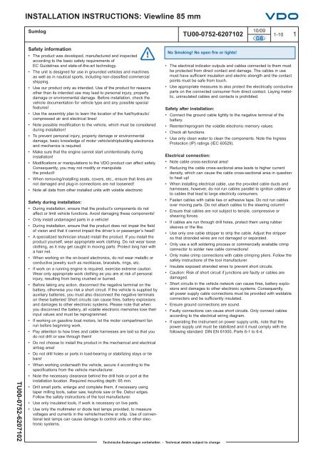
<strong>INSTALLATION</strong> <strong>INSTRUCTIONS</strong>: <strong>Viewline</strong> <strong>85</strong> <strong>mm</strong>Sumlog10/09TU00-0752-6207102 1-10 1GBTU00-0752-6207102Safety information• The product was developed, manufactured and inspectedaccording to the basic safety requirements ofEC Guidelines and state-of-the-art technology.• The unit is designed for use in grounded vehicles and machinesas well as in nautical sports, including non-classified co<strong>mm</strong>ercialshipping.• Use our product only as intended. Use of the product for reasonsother than its intended use may lead to personal injury, propertydamage or environmental damage. Before installation, check thevehicle documentation for vehicle type and any possible specialfeatures!• Use the assembly plan to learn the location of the fuel/hydraulic/compressed air and electrical lines!• Note possible modification to the vehicle, which must be consideredduring installation!• To prevent personal injury, property damage or environmentaldamage, basic knowledge of motor vehicle/shipbuilding electronicsand mechanics is required.• Make sure that the engine cannot start unintentionally duringinstallation!• Modifications or manipulations to the VDO product can affect safety.Consequently, you may not modify or manipulatethe product!• When removing/installing seats, covers, etc., ensure that lines arenot damaged and plug-in connections are not loosened!• Note all data from other installed units with volatile electronicSafety during installation:• During installation, ensure that the product’s components do notaffect or limit vehicle functions. Avoid damaging these components!• Only install undamaged parts in a vehicle!• During installation, ensure that the product does not impair the fieldof vision and that it cannot impact the driver’s or passenger’s head!• A specialized technician should install the product. If you install theproduct yourself, wear appropriate work clothing. Do not wear looseclothing, as it may get caught in moving parts. Protect long hair witha hair net.• When working on the on-board electronics, do not wear metallic orconductive jewelry such as necklaces, bracelets, rings, etc.• If work on a running engine is required, exercise extreme caution.Wear only appropriate work clothing as you are at risk of personalinjury, resulting from being crushed or burned.• Before taking any action, disconnect the negative terminal on thebattery, otherwise you risk a short circuit. If the vehicle is supplied byauxiliary batteries, you must also disconnect the negative terminalson these batteries! Short circuits can cause fires, battery explosionsand damages to other electronic systems. Please note that whenyou disconnect the battery, all volatile electronic memories lose theirinput values and must be reprogra<strong>mm</strong>ed.• If working on gasoline boat motors, let the motor compartment fanrun before beginning work.• Pay attention to how lines and cable harnesses are laid so that youdo not drill or saw through them!• Do not choose to install the product in the mechanical and electricalairbag area!• Do not drill holes or ports in load-bearing or stabilizing stays or tiebars!• When working underneath the vehicle, secure it according to thespecifications from the vehicle manufacturer.• Note the necessary clearance behind the drill hole or port at theinstallation location. Required mounting depth: 65 <strong>mm</strong>.• Drill small ports; enlarge and complete them, if necessary usingtaper milling tools, saber saw, keyhole saw or file. Debur edges.Follow the safety instructions of the tool manufacturer.• Use only insulated tools, if work is necessary on live parts.• Use only the multimeter or diode test lamps provided, to measurevoltages and currents in the vehicle/machine or ship. Use of conventionaltest lamps can cause damage to control units or other electronicsystems.No Smoking! No open fire or lights!Technische Änderungen vorbehalten - Technical details subject to change• The electrical indicator outputs and cables connected to them mustbe protected from direct contact and damage. The cables in usemust have sufficient insulation and electric strength and the contactpoints must be safe from touch.• Use appropriate measures to also protect the electrically conductiveparts on the connected consumer from direct contact. Laying metallic,uninsulated cables and contacts is prohibited.Safety after installation:• Connect the ground cable tightly to the negative terminal of thebattery.• Reenter/reprogram the volatile electronic memory values.• Check all functions.• Use only clean water to clean the components. Note the IngressProtection (IP) ratings (IEC 60529).Electrical connection:• Note cable cross-sectional area!• Reducing the cable cross-sectional area leads to higher currentdensity, which can cause the cable cross-sectional area in questionto heat up!• When installing electrical cable, use the provided cable ducts andharnesses, however, do not run cables parallel to ignition cables orto cables that lead to large electricity consumers.• Fasten cables with cable ties or adhesive tape. Do not run cablesover moving parts. Do not attach cables to the steering column!• Ensure that cables are not subject to tensile, compressive orshearing forces.• If cables are run through drill holes, protect them using rubbersleeves or the like.• Use only one cable stripper to strip the cable. Adjust the stripperso that stranded wires are not damaged or separated.• Only use a soft soldering process or co<strong>mm</strong>ercially available crimpconnector to solder new cable connections!• Only make crimp connections with cable crimping pliers. Follow thesafety instructions of the tool manufacturer.• Insulate exposed stranded wires to prevent short circuits.• Caution: Risk of short circuit if junctions are faulty or cables aredamaged.• Short circuits in the vehicle network can cause fires, battery explosionsand damages to other electronic systems. Consequently,all power supply cable connections must be provided with weldableconnectors and be sufficiently insulated.• Ensure ground connections are sound.• Faulty connections can cause short circuits. Only connect cablesaccording to the electrical wiring diagram.• If operating the instrument on power supply units, note that thepower supply unit must be stabilized and it must comply with thefollowing standard: DIN EN 61000, Parts 6-1 to 6-4.
<strong>INSTALLATION</strong> <strong>INSTRUCTIONS</strong>: <strong>Viewline</strong> <strong>85</strong> <strong>mm</strong>SumlogProcedures for installing VDO <strong>Viewline</strong> instruments110/09TU00-0752-6207102 1-10 2GBBefore beginning, turn off the ignition and removethe ignition key. If necessary, remove the main circuitswitch.2Disconnect the negative terminal on the battery.Make sure the battery cannot unintentionally restart.• Before taking any action, disconnect the negative terminal on the battery, otherwise you risk a shortcircuit. If the vehicle is supplied by auxiliary batteries, you must also disconnect the negative terminalson these batteries! Short circuits can cause fires, battery explosions and damages to other electronicsystems. Please note that when you disconnect the battery, all volatile electronic memories lose theirinput values and must be reprogra<strong>mm</strong>ed.30.3 mIf installing the instrument near a magnetic compass,note the magnetic safe distance to the compass.45The following rings may be installed as alternatives tothe supplied front ring:Front ring, flat; blackA2C53192911Front ring, flat; whiteA2C53192912Front ring, flat; chrome A2C53192910Front ring, triangular; black A2C53192917Front ring, triangular; white A2C53192920Front ring, triangular; chrome A2C53192918Front ring, round; black A2C53192913Front ring, round; white A2C53192916Front ring, round; chrome A2C53192914Place the new front ring on the instrument, rotate ituntil the ring’s lip locks into the slots in the housingand press the front ring until it is flush with the instrumentglass.1 26Ø 86 <strong>mm</strong>2 ... 20 <strong>mm</strong>Conventional assembly. (Instrument is put into thedrill hole from the front).The panel width may be within a range of 2 to 20 <strong>mm</strong>.The drill hole must have a diameter of 86 <strong>mm</strong>.• Do not drill holes or ports in load-bearing or stabilizing stays or tie bars!• Note the necessary clearance behind the drill hole or port at the installation location. Required mounting depth:65 <strong>mm</strong>.• Drill small ports; enlarge and complete them, if necessary using taper milling tools, saber saw, keyhole saw orfile. Debur edges. Follow the safety instructions of the tool manufacturer.TU00-0752-62071027AoderorouoBTechnische Änderungen vorbehalten - Technical details subject to changeFor <strong>85</strong> <strong>mm</strong> instruments, the fastening nut can bemounted at position A or B. This allows you to fixe thegauge in different panel bores.Version AVersion BPanel bore 80.5 - 81 <strong>mm</strong>Circumferential lip away from instrumentPanel bore <strong>85</strong>.5 - 86 <strong>mm</strong>Circumferential lip next to instrument
<strong>INSTALLATION</strong> <strong>INSTRUCTIONS</strong>: <strong>Viewline</strong> <strong>85</strong> <strong>mm</strong>Sumlog810/09TU00-0752-6207102 1-10 3GBIf the instrument is mounted flush (i.e., from the backso that the instrument glass and the panel form oneplane), the front ring must be removed. Press theinstrument glass with both thumbs, while at the sametime pressing the front ring forward from the instrumentwith both index fingers. Note the use of a toolin the adjacent figure.129ø 75.4 <strong>mm</strong>Flush assembly.The reco<strong>mm</strong>ended panel thickness is 1.5 to 3 <strong>mm</strong>.The drill hole must have a diameter of 75.4 <strong>mm</strong>.Ensure that the installation location is level and hasno sharp edges.101.5...3 <strong>mm</strong>• Do not drill holes or ports in load-bearing or stabilizing stays or tie bars!• Note the necessary clearance behind the drill hole or port at the installation location. Required mounting depth:65 <strong>mm</strong>.• Drill small ports; enlarge and complete them, if necessary using taper milling tools, saber saw, keyhole saw orfile. Debur edges. Follow the safety instructions of the tool manufacturer.Place the flush mount seal A2C53215641 on theinstrument glass.Put the instrument into the drill hole from the back.Adjust the instrument so that the gauge is level andfasten it to the stud bolts on the rear side of the panel,using the flush mount fixing bracket A2C59510864.1171Depending on the configuration, insert the cable into the 8-pin and 14-pincontact housing according to the following pin assignment. The contacts mustaudibly lock into place.TU00-0752-620710214<strong>85</strong>1848-pin contact housing14-pin contact housingPin 1 - T. 30 - battery12/24 V Pin 1 - NMEA0183-BPin 2 - T. 31 - groundPin 2 - NMEA0183-APin 3 - signal groundPin 3 - unassignedPin 4 - T. 15 - ignition plusPin 4 - unassignedPin 5 - sensor signalPin 5 - unassignedPin 6 - T. 58 - lightingPin 6 - unassignedPin 7 - warning LED ground Pin 7 - unassignedPin 8 - warning LED plusPin 8 - unassignedPin 9 - unassignedPin 10 - unassignedPin 11 - Configuration keyPin 12 - Mode keyPin 13 - Alarm output (max 100 mA)Pin 14 - unassignedNow insert the plug into the gauge. Note the inverse polarity protection nosein the process.Technische Änderungen vorbehalten - Technical details subject to change
<strong>INSTALLATION</strong> <strong>INSTRUCTIONS</strong>: <strong>Viewline</strong> <strong>85</strong> <strong>mm</strong>Sumlog12Connector set, 14-pin -A2C59510<strong>85</strong>1Electrical connection:• Electrical connection:• Note cable cross-sectional area!Connector set, 8-pin -A2C59510<strong>85</strong>0• Reducing the cable cross-sectional area leads to higher currentdensity, which can cause the cable cross-sectional area in questionto heat up!• When installing electrical cable, use the provided cable ducts andharnesses, however, do not run cables parallel to ignition cablesor to cables that lead to large electricity consumers.• Fasten cables with cable ties or adhesive tape. Do not run cables overmoving parts. Do not attach cables to the steering column!• Ensure that cables are not subject to tensile, compressive or shearingforces.• If cables are run through drill holes, protect them using rubber sleevesor the like.• Use only one cable stripper to strip the cable. Adjust the stripper sothat stranded wires are not damaged or separated.• Only use a soft soldering process or co<strong>mm</strong>ercially available crimpconnector to solder new cable connections!10/09TU00-0752-6207102 1-10 4GBUse the following connector to connect the instrument:Connector set, 8-pin - A2C59510<strong>85</strong>0Connector set, 14-pin - A2C59510<strong>85</strong>1The connector set is designed for a cable cross-sectionof 0.25 - 0.5 <strong>mm</strong> 2 .For other cross-sections, please use contacts made by Tyco.Single contacts: Tyco No. 1355718-1 for 0.14 – 0.22 <strong>mm</strong> 2Tyco No. 963729-1 for 0.5 – 0.75 <strong>mm</strong> 2Strip: Tyco No. 1355717-1 for 0.14 – 0.22 <strong>mm</strong> 2Tyco No. 963715-1 for 0.5 – 0.75 <strong>mm</strong> 2Create a crimp connection using the contacts and the correspondingcables. Follow the instructions of the hand pliersmanufacturer. Use the following for this:Hand pliers Tyco No. 539635-1And the tool Tyco No. 539682-2 for these hand pliers.Pay special attention to whether the crimp barrel clutches allindividual wires in the cable, otherwise you risk a short circuit!• Only make crimp connections with cable crimping pliers. Follow thesafety instructions of the tool manufacturer.• Insulate exposed stranded wires to prevent short circuits.• Caution: Risk of short circuit if junctions are faulty or cables aredamaged.• Short circuits in the vehicle network can cause fires, battery explosionsand damages to other electronic systems. Consequently,all power supply cable connections must be provided with weldableconnectors and sufficiently insulated.• Ensure ground connections are sound.• Faulty connections can cause short circuits. Only connect cablesaccording to the electrical wiring diagram.• If operating the instrument on power supply units, note thatthe power supply unit must be stabilized and it must comply withthe following standard: DIN EN 61000, Parts 6-1 to 6-4.13Designations in the wiring diagram:30 - terminal 30 - steady-state plus 12 V15 - terminal 15 - connected (ignition) plus58 - terminal 58 - lighting31 - terminal 31 - groundF1 - fuse 5A quick-responseS1 - light switchC1 - 8-pin MQS connectorC2 - 14-pin MQS connectorConfig - Configuration keyMode - Mode keyW1 - Alarm output (max. 100 mA)You must comply with the wiring diagram.8-pin connection14-pin connectionSensorTU00-0752-6207102PC 9-pin Sub D pin 2PC 9-pin Sub D pin 3PC 9-pin Sub D pin 5SensorminusTechnische Änderungen vorbehalten - Technical details subject to change
<strong>INSTALLATION</strong> <strong>INSTRUCTIONS</strong>: <strong>Viewline</strong> <strong>85</strong> <strong>mm</strong>Sumlog14*10/09TU00-0752-6207102 1-10 5GBAlign the instrument and hand-tighten the fasteningnut. Ensure that the nut is not tightened with a torquegreater than 400 Ncm.* Make sure the seal lays flat between the panel andthe front ring.15If you would like to omit the fastening nut, you mayuse the part set A2C59510<strong>85</strong>4 as an alternative.This is reco<strong>mm</strong>ended if the installation location issubject to vibratory loads.Screw the stud bolts into the provided drill holes inthe enclosure. Max. stud bolt torque is 1.5 Nm16Place the bracket on the stud bolt and hand-tightenthe knurled nut.* Make sure the seal lays flat between the panel andthe front ring (see Fig. 14).17Close the battery after inspecting the connection.• Please note that when you disconnect the battery, all volatileelectronic memories lose their input values and must be reprogra<strong>mm</strong>ed.18If necessary, replace the main circuit switch. Turn on the ignitionand conduct a functional test. Reprogram other instruments thatmay have lost their saved settings.TU00-0752-6207102Technische Änderungen vorbehalten - Technical details subject to change
<strong>INSTALLATION</strong> <strong>INSTRUCTIONS</strong>: <strong>Viewline</strong> <strong>85</strong> <strong>mm</strong>Sumlog19 OperationBasics:10/09TU00-0752-6207102 1-10 6Press the key briefly (< 2sec.) to change the currently displayed value.Press the key longer (> 2sec.) to change to the next value.The display returns to normal operating mode if a key is not pressed for 30 seconds.Any settings you have made are not saved.GBStartup1. Setting the signal source and pulse count1. Activate T. 30 (8-pin - Pin1)2. Deactivate T. 15 (8-pin - Pin4)3. Press and hold Config key (14-pin - Pin 11)Activate T. 15Release Config keyPress and hold Config keyPress the Config. key to changeover between the frequencyinput (8-pole plug, Pin 5) and the NMEA0183 input (14-poleplug, Pins 1 and 2).Press Config key brieflyPress and hold Config keySet impulse number is displayed, the first digit flashes.Press Config key brieflyThe flashing digit increases by 1. If the flashing digit is “9”,the display returns to “0”Press Config key brieflyThe next lower digit flashesPress Config key brieflyThe flashing digit increases by 1. If the flashing digit is “9”,the display returns to “0”TU00-0752-6207102Continue until the complete impulse number is setPress and hold Config keyTechnische Änderungen vorbehalten - Technical details subject to changeDeactivate T. 15. This saves the impulse number in thedisplay.
<strong>INSTALLATION</strong> <strong>INSTRUCTIONS</strong>: <strong>Viewline</strong> <strong>85</strong> <strong>mm</strong>Sumlog2. Setting the unit and alarm threshold10/09TU00-0752-6207102 1-10 7GB1. Activate T. 30 (8-pin - Pin1)2. Deactivate T. 15 (8-pin - Pin4)3. Press and hold Mode key (14-pin - Pin 12)Activate T. 15Release Mode keyPress and hold Mode keyBy briefly pressing the Mode key, you can switch between24h and 12h (AM/PM) clock format.Press and hold Mode keyPress the Mode key to change the water temperatureunit from °C to °F.Press and hold Mode keyPress Mode key briefly to change the water depthunit from von m to ft.Press and hold Mode keyPress Mode key brieflyPress and hold Mode keySet alarm threshold is displayed; the first digit flashes.Press Mode key brieflyThe flashing digit increases by 1. If the flashing digit is “9”,the display returns to “0”Press and hold Mode keyThe next lower digit flashes.Press Mode key brieflyThe flashing digit increases by 1. If the flashing digit is “9”,the display returns to “0”TU00-0752-6207102Continue until the complete alarm threshold is set.Press and hold Mode keyTechnische Änderungen vorbehalten - Technical details subject to changeDeactivate T. 15. This saves the unit and the alarm thresholdin the display.
<strong>INSTALLATION</strong> <strong>INSTRUCTIONS</strong>: <strong>Viewline</strong> <strong>85</strong> <strong>mm</strong>SumlogIn operation1. Display indicator selectionOdometer10/09TU00-0752-6207102 1-10 81. Activate T. 30 (8-pin - Pin1)2. Activate T. 15 (8-pin - Pin4)GBTripometerPress Mode key brieflyPress Mode key brieflyDepthPress Mode key brieflyTimeWater temperaturePress Mode key brieflyPress Mode key brieflyOn-boardvoltage2. Resetting the day counter1. Activate T. 30 (8-pin - Pin1)2. Activate T. 15 (8-pin - Pin4)Press the Mode key repeatedly until the trip distance are displayedPress and hold Mode keyTU00-0752-6207102Trip is now deleted.Technische Änderungen vorbehalten - Technical details subject to change
<strong>INSTALLATION</strong> <strong>INSTRUCTIONS</strong>: <strong>Viewline</strong> <strong>85</strong> <strong>mm</strong>Sumlog3. Setting the clock10/09TU00-0752-6207102 1-10 9GB1. Activate T. 30 (8-pin - Pin1)2. Activate T. 15 (8-pin - Pin4)Press the Mode key repeatedly until the time is displayedPress and hold Mode keySet time is displayed; the first digit flashes.Press Mode key brieflyThe flashing digit increases by 1. If the flashing digit is “9”,the display returns to “0”Press and hold Mode keyThe next lower digit flashes.Press Mode key brieflyThe flashing digit increases by 1. If the flashing digit is “9”,the display returns to “0”Continue until the correct time is setPress and hold Mode keyClock is set.Important: If T. 30 (8-pin - Pin1) is deactivated, the clock nolonger runs.4. Setting the brightness1. Activate T. 30 (8-pin - Pin1)2. Activate T. 15 (8-pin - Pin4)Press the Mode key repeatedly until the on-board voltageis displayedPress and hold Mode keyPress the Mode key repeatedly until the desired brightnessis reached The brightness can be set between 0 (OFF)to 10 (max).TU00-0752-6207102Press and hold Mode keyThe desired brightness is now permanently set.Technische Änderungen vorbehalten - Technical details subject to change
<strong>INSTALLATION</strong> <strong>INSTRUCTIONS</strong>: <strong>Viewline</strong> <strong>85</strong> <strong>mm</strong>Sumlog2010/09TU00-0752-6207102 1-10 10GBTo remove the connector, press the latch (1) and pullthe connector out (2).1221Important: Clean the instrument glass and front frame with water only. Do not use chemical agents.22Accessories / Spare partsBush contacts 0.25 – 0.5 <strong>mm</strong> 2 A2C59510846Bush housing, 8-pinA2C59510847Bush housing, 14-pinA2C59510848Hand pliers Tyco No. 539635-1Tool for hand pliers Tyco No. 539682-2.Single contacts 0.14 – 0.22 <strong>mm</strong> 2 Tyco No. 1355718-1Single contacts 0.5 – 0.75 <strong>mm</strong> 2 Tyco No. 963729-1Strip 0.14 – 0.22 <strong>mm</strong> 2 Tyco No. 1355717-1Strip 0.25 – 0.5 <strong>mm</strong> 2 Tyco No. 928999-1Strip 0.5 – 0.75 <strong>mm</strong> 2 Tyco No. 963715-1Bracket assembly mounting set A2C59510<strong>85</strong>4Flush mount fixing bracket A2C59510864Flush mount sealFastening nutFront ring, flat; blackFront ring, flat; whiteFront ring, flat; chromeFront ring, triangular; blackFront ring, triangular; whiteFront ring, triangular; chromeFront ring, round; blackFront ring, round; whiteFront ring, round; chromeProtective connector cap, 8-pinProtective connector cap, 14-pinA2C53215641A2C53212238A2C53192911A2C53192912A2C53192910A2C53192917A2C53192920A2C53192918A2C53192913A2C53192916A2C53192914A2C53324664A2C53324671TU00-0752-6207102Technische Änderungen vorbehalten - Technical details subject to change