INSTALLATION INSTRUCTIONS: Viewline 85 mm - Howard ...
INSTALLATION INSTRUCTIONS: Viewline 85 mm - Howard ...
INSTALLATION INSTRUCTIONS: Viewline 85 mm - Howard ...

Create successful ePaper yourself
Turn your PDF publications into a flip-book with our unique Google optimized e-Paper software.
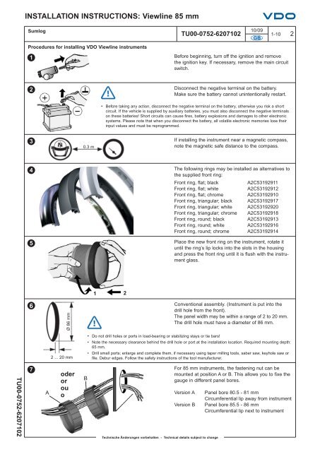
<strong>INSTALLATION</strong> <strong>INSTRUCTIONS</strong>: <strong>Viewline</strong> <strong>85</strong> <strong>mm</strong>SumlogProcedures for installing VDO <strong>Viewline</strong> instruments110/09TU00-0752-6207102 1-10 2GBBefore beginning, turn off the ignition and removethe ignition key. If necessary, remove the main circuitswitch.2Disconnect the negative terminal on the battery.Make sure the battery cannot unintentionally restart.• Before taking any action, disconnect the negative terminal on the battery, otherwise you risk a shortcircuit. If the vehicle is supplied by auxiliary batteries, you must also disconnect the negative terminalson these batteries! Short circuits can cause fires, battery explosions and damages to other electronicsystems. Please note that when you disconnect the battery, all volatile electronic memories lose theirinput values and must be reprogra<strong>mm</strong>ed.30.3 mIf installing the instrument near a magnetic compass,note the magnetic safe distance to the compass.45The following rings may be installed as alternatives tothe supplied front ring:Front ring, flat; blackA2C53192911Front ring, flat; whiteA2C53192912Front ring, flat; chrome A2C53192910Front ring, triangular; black A2C53192917Front ring, triangular; white A2C53192920Front ring, triangular; chrome A2C53192918Front ring, round; black A2C53192913Front ring, round; white A2C53192916Front ring, round; chrome A2C53192914Place the new front ring on the instrument, rotate ituntil the ring’s lip locks into the slots in the housingand press the front ring until it is flush with the instrumentglass.1 26Ø 86 <strong>mm</strong>2 ... 20 <strong>mm</strong>Conventional assembly. (Instrument is put into thedrill hole from the front).The panel width may be within a range of 2 to 20 <strong>mm</strong>.The drill hole must have a diameter of 86 <strong>mm</strong>.• Do not drill holes or ports in load-bearing or stabilizing stays or tie bars!• Note the necessary clearance behind the drill hole or port at the installation location. Required mounting depth:65 <strong>mm</strong>.• Drill small ports; enlarge and complete them, if necessary using taper milling tools, saber saw, keyhole saw orfile. Debur edges. Follow the safety instructions of the tool manufacturer.TU00-0752-62071027AoderorouoBTechnische Änderungen vorbehalten - Technical details subject to changeFor <strong>85</strong> <strong>mm</strong> instruments, the fastening nut can bemounted at position A or B. This allows you to fixe thegauge in different panel bores.Version AVersion BPanel bore 80.5 - 81 <strong>mm</strong>Circumferential lip away from instrumentPanel bore <strong>85</strong>.5 - 86 <strong>mm</strong>Circumferential lip next to instrument