INSTALLATION INSTRUCTIONS: Viewline 85 mm - Howard ...
INSTALLATION INSTRUCTIONS: Viewline 85 mm - Howard ...
INSTALLATION INSTRUCTIONS: Viewline 85 mm - Howard ...

You also want an ePaper? Increase the reach of your titles
YUMPU automatically turns print PDFs into web optimized ePapers that Google loves.
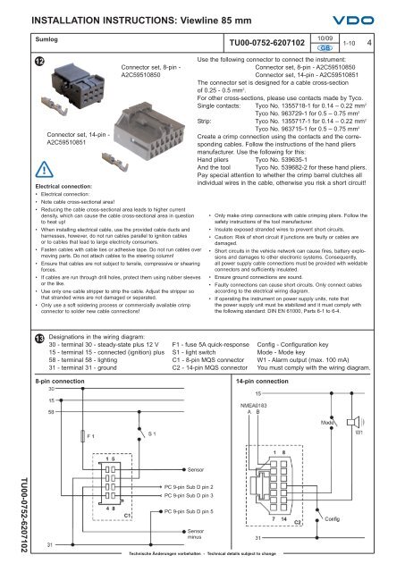
<strong>INSTALLATION</strong> <strong>INSTRUCTIONS</strong>: <strong>Viewline</strong> <strong>85</strong> <strong>mm</strong>Sumlog12Connector set, 14-pin -A2C59510<strong>85</strong>1Electrical connection:• Electrical connection:• Note cable cross-sectional area!Connector set, 8-pin -A2C59510<strong>85</strong>0• Reducing the cable cross-sectional area leads to higher currentdensity, which can cause the cable cross-sectional area in questionto heat up!• When installing electrical cable, use the provided cable ducts andharnesses, however, do not run cables parallel to ignition cablesor to cables that lead to large electricity consumers.• Fasten cables with cable ties or adhesive tape. Do not run cables overmoving parts. Do not attach cables to the steering column!• Ensure that cables are not subject to tensile, compressive or shearingforces.• If cables are run through drill holes, protect them using rubber sleevesor the like.• Use only one cable stripper to strip the cable. Adjust the stripper sothat stranded wires are not damaged or separated.• Only use a soft soldering process or co<strong>mm</strong>ercially available crimpconnector to solder new cable connections!10/09TU00-0752-6207102 1-10 4GBUse the following connector to connect the instrument:Connector set, 8-pin - A2C59510<strong>85</strong>0Connector set, 14-pin - A2C59510<strong>85</strong>1The connector set is designed for a cable cross-sectionof 0.25 - 0.5 <strong>mm</strong> 2 .For other cross-sections, please use contacts made by Tyco.Single contacts: Tyco No. 1355718-1 for 0.14 – 0.22 <strong>mm</strong> 2Tyco No. 963729-1 for 0.5 – 0.75 <strong>mm</strong> 2Strip: Tyco No. 1355717-1 for 0.14 – 0.22 <strong>mm</strong> 2Tyco No. 963715-1 for 0.5 – 0.75 <strong>mm</strong> 2Create a crimp connection using the contacts and the correspondingcables. Follow the instructions of the hand pliersmanufacturer. Use the following for this:Hand pliers Tyco No. 539635-1And the tool Tyco No. 539682-2 for these hand pliers.Pay special attention to whether the crimp barrel clutches allindividual wires in the cable, otherwise you risk a short circuit!• Only make crimp connections with cable crimping pliers. Follow thesafety instructions of the tool manufacturer.• Insulate exposed stranded wires to prevent short circuits.• Caution: Risk of short circuit if junctions are faulty or cables aredamaged.• Short circuits in the vehicle network can cause fires, battery explosionsand damages to other electronic systems. Consequently,all power supply cable connections must be provided with weldableconnectors and sufficiently insulated.• Ensure ground connections are sound.• Faulty connections can cause short circuits. Only connect cablesaccording to the electrical wiring diagram.• If operating the instrument on power supply units, note thatthe power supply unit must be stabilized and it must comply withthe following standard: DIN EN 61000, Parts 6-1 to 6-4.13Designations in the wiring diagram:30 - terminal 30 - steady-state plus 12 V15 - terminal 15 - connected (ignition) plus58 - terminal 58 - lighting31 - terminal 31 - groundF1 - fuse 5A quick-responseS1 - light switchC1 - 8-pin MQS connectorC2 - 14-pin MQS connectorConfig - Configuration keyMode - Mode keyW1 - Alarm output (max. 100 mA)You must comply with the wiring diagram.8-pin connection14-pin connectionSensorTU00-0752-6207102PC 9-pin Sub D pin 2PC 9-pin Sub D pin 3PC 9-pin Sub D pin 5SensorminusTechnische Änderungen vorbehalten - Technical details subject to change