
You also want an ePaper? Increase the reach of your titles
YUMPU automatically turns print PDFs into web optimized ePapers that Google loves.
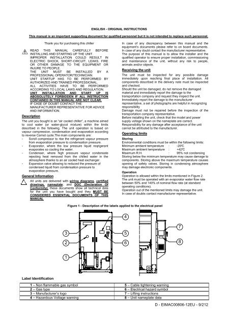
ENGLISH - ORIGINAL INSTRUCTIONSThis manual is an important supporting document for qualified personnel but it is not intended to replace such personnel.Thank you for purchasing this chillerREAD THIS MANUAL CAREFULLY BEFOREINSTALLING AND STARTING UP THE UNIT.IMPROPER INSTALLATION COULD RESULT INELECTRIC SHOCK, SHORT-CIRCUIT, LEAKS, FIREOR OTHER DAMAGE TO THE EQUIPMENT ORINJURE TO PEOPLE.THE UNIT MUST BE INSTALLED BY APROFESSIONAL OPERATOR/TECHNICIAN.UNIT STARTUP HAS TO BE PERFORMED BYAUTHORIZED AND TRAINED PROFESSIONAL.ALL ACTIVITIES HAVE TO BE PERFORMEDACCORDING TO LOCAL LAWS AND REGULATION.UNIT INSTALLATION AND START UP ISABOSOLUTELY FORBIDDEN IF ALL INSTRUCTIONCONTAINED IN THIS MANUAL ARE NOT CLEAR.IF CASE OF DOUBT CONTACT THEMANUFACTURER REPRESENTATIVE FOR ADVICEAND INFORMATION.DescriptionThe unit you bought is an “air cooled chiller”, a machine aimedto cool water (or water-glycol mixture) within the limitsdescribed in the following. The unit operation is based onvapour compression, condensation and evaporation accordingto reverse Carnot cycle.The main components are:- Scroll compressor to rise the refrigerant vapour pressurefrom evaporation pressure to condensation pressure.- Evaporator, where the low pressure liquid reqrigerantevaporates so cooling the water.- Condenser, where high pressure vapour condensaterejecting heat removed from the chilled water in theatmosphere thanks to an air cooled heat exchanger.- Expansion valve allowing to reduced the pressure ofcondensed liquid from condensation pressure toevaporation pressure.General InformationAll units are delivered with wiring diagrams, certifieddrawings, nameplate; and DOC (Declaration OfConformity); these documents show all technical datafor the unit you have bought and they MUST BECONSIDERED ESSENTIAL DOCUMENTS OF THISMANUALIn case of any discrepancy between this manual and theequipment’s documents please refer to on board documents.In case of any doubt contact the manufacturer representative.The purpose of this manual is to allow the installer and thequalified operator to ensure proper installation, commissioningand maintenance of the unit, without any risk to people,animals and/or objects.Receiving the unitThe unit must be inspected for any possible damageimmediately upon reaching final place of installation. Allcomponents described in the delivery note must be inspectedand checked.Should the unit be damaged, do not remove the damagedmaterial and immediately report the damage to thetransportation company and request they inspect the unit.Immediately report the damage to the manufacturerrepresentative, a set of photographs are helpful in recognizingresponsibilityDamage must not be repaired before the inspection of thetransportation company representative.Before installing the unit, check that the model and powersupply voltage shown on the nameplate are correct.Responsibility for any damage after acceptance of the unitcannot be attributed to the manufacturer.Operating limitsStoringEnvironmental conditions must be within the following limits:Minimum ambient temperature : -20°CMaximum ambient temperature : +42°CMaximum R.H. : 95% not condensingStoring below the minimum temperature may cause damage tocomponents. Storing above the maximum temperature causesopening of safety valves. Storing in condensing atmospheremay damage electronic components.OperationOperation is allowed within the limits mentioned in Figure 2.The unit must be operated with an evaporator water flow ratebetween 50% and 140% of nominal flow rate (at standardoperating conditions).Operation out of the mentioned limits may damage the unit.In case of doubts contact manufacturer representative.Figure 1 - Description of the labels applied to the electrical panelLabel Identification1 – Non flammable gas symbol 5 – Cable tightening warning2 – Gas type 6 – Electrical hazard symbol3 – Manufacturer’s logo 7 – Lifting instructions4 – Hazardous Voltage warning 8 – Unit nameplate dataD - <strong>EIMAC00806</strong>-<strong>12EU</strong> - 9/212