Betriebsanleitung Sicherheitsschalter NM..HB - EUCHNER GmbH + ...
Betriebsanleitung Sicherheitsschalter NM..HB - EUCHNER GmbH + ...
Betriebsanleitung Sicherheitsschalter NM..HB - EUCHNER GmbH + ...

Create successful ePaper yourself
Turn your PDF publications into a flip-book with our unique Google optimized e-Paper software.
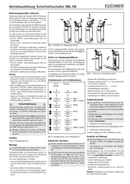
Operating Instructions Safety Switch <strong>NM</strong>..<strong>HB</strong>Correct useSafety switches of type series <strong>NM</strong>..<strong>HB</strong> (lever arm)are used in control systems that perform safetyfunctions, e.g. for safety guards or as positionencoders.The safety switches series <strong>NM</strong> comply with theregulations of EN 60947-5-1, Annex K and complywith the requirements of the employers’ liabilityinsurance associations for machines, installations andpersonnel protection.Before safety switches are used, a risk assessmentmust be performed on the machine in accordancewith EN ISO 13849-1, Safety of machinery. Safety relatedparts of control systems. General principles fordesign EN ISO 14121, Safety of machinery. Riskassessment. Principles IEC 62061, Safety of machinery. Functional safetyof safety-related electrical, electronic andprogrammable electronic control systems.Correct use includes compliance with the relevantrequirements for installation and operation, particularly EN ISO 13849-1, Safety of machinery. Safety relatedparts of control systems. General principles fordesign EN 1088, Safety of machinery. Interlocking devicesassociated with guards. Principles for design andselection EN 60204-1, Electrical equipment of machinesImportant: The user is responsible for the integration of thedevice in a safe overall system. For this purposethe overall system must be validated, e.g. inaccordance with EN ISO 13849-2. If the simplified method according to section 6.3EN ISO 13849-1:2008 is used for validation, thePerformance Level (PL) may be reduced if severaldevices are connected one after the other. If a product data sheet is included with the product,the information on the data sheet applies in case ofdiscrepancies with the operating instructions.Safety precautionsSafety switches fulfill a personal protection function.Incorrect installation or tampering can lead to severeinjuries to personnel.Safety components must not be bypassed(bridging of contacts), turned away, removed orotherwise rendered ineffective.On this topic pay attention in particular to themeasures for reducing the possibility of bypassingfrom EN 1088:1995+A2:2008, section 5.7.Mounting, electrical connection and setup onlyby authorized personnel.FunctionSee travel diagram.MountingSafety switches and trip dogs must not be usedas an end stop.Safety switches and trip dogs must be arranged suchthat they are adequately secured against movement.To meet these requirements: The fixings must be reliable and must also requirethe use of a tool to undo them. Mount the safety switch positively. For safety-related applications (fixed positioning),mount switch with M5x30 screws.To ensure correct operation, the trip dogs must be fittedas per the dimension 41 +1 0 (see Figure 4 and 5).Figure 1: Changing the actuating directionProtection against environmental influencesA lasting and correct safety function requires that theactuating head must be protected against thepenetration of foreign bodies such as swarf, sand,blasting shot, etc.Cover the actuating head, the trip dog and the ratingplate during painting work!Only use solvent-free cleaning agents to clean thesafety switch!Switching elements and switching functionsNotactuated212113312131211331211121112222143222322214322212Actuated212113312131211331211122 2112 11Figure 2: Switching elements and switching functionsElectrical connectionWhen choosing the insulation material and wirefor the connections, pay attention to the overtemperaturein the housing (depending on theoperating conditions)!For use and applications as per the requirementsof , a class 2 power supply or a class 2transformer according to UL1310 or UL1585must be used. As an alternative, a low voltagepower supply according to UL508 table 32.1can be used.A2222143222322214322212<strong>NM</strong>01<strong>NM</strong>11,<strong>NM</strong>11..C2069<strong>NM</strong>02<strong>NM</strong>12<strong>NM</strong>0322 <strong>NM</strong>02..C206912Fig. 3:Opening the safety switchBreak out the required entry opening. Fit cable gland M16 x 1.5 with appropriate degreeof protection. Conductor cross-section 0.34 mm 2 ... 1.5 mm². For terminal assignment see Figure 2. Tighten the screws with a torque of 0.5 Nm. Check that the cable entry is sealed. Close the cover and screw in position.Functional checkM=0,6NmWhen the safety guard is open, the safety switchmust be actuated in any safety guard position(overrun protection). In safety circuits, check the safety function. The machine must stop when the safety switch isactuated. The machine must not start when the safety switchis actuated. Mechanical function testCheck the actuating element for freedom ofmovement. Electrical function testActuate switch and check the switching function.Inspection and serviceIf damage or wear is found, the complete switchand actuator assembly must be replaced.Replacement of individual parts or assembliesis not permitted!No servicing is required, but regular inspection ofthe following is necessary to ensure trouble-free longtermoperation: correct switching function secure mounting of components dirt and wear sealing of cable entry loose cable connections or plug connectors.Note:The year of manufacture can be seen in thebottom, right corner of the rating plate.
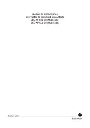
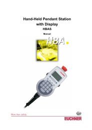
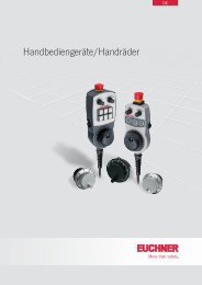
Operating Instructions Safety Switch <strong>NM</strong>..<strong>HB</strong>128,584632253212,512,5Dog1,51641 +1 0∅5∅4,2M16x1,5CM=0,6NmB17 *16,51825R627 250°11-12<strong>NM</strong>03 21-22<strong>NM</strong>12 <strong>NM</strong>11<strong>NM</strong>02 31-32M=1 NmM=0,6NmM16x1,5DM=0,6NmAStandard35°*fixed positioning for safetyrelatedapplications (M5)Figure 4: Dimension drawing <strong>NM</strong>11<strong>HB</strong> / <strong>NM</strong>02<strong>HB</strong> / <strong>NM</strong>12<strong>HB</strong> / <strong>NM</strong>03<strong>HB</strong>97,5M16x1,5*fixed positioning for safety-related applications(M5)846322512,5321,541 +1 0∅5∅4,2M=0,6NmCM=0,6Nm<strong>NM</strong>01B21-2217 *16,518250˚DogR627 2535˚60˚65˚M=1 NmD60° 65°M=0,6NmAStandard<strong>NM</strong>02(C2069)<strong>NM</strong>11(C2069)0˚21-2231-320˚13-1421-220°13-1421-2231-3235˚35˚45˚35°45°65˚60˚60˚65˚60° 65°Exclusion of liability under the followingcircumstances incorrect use non-compliance with safety regulations installation and electrical connection not performedby authorized personnel. failure to perform functional checks.EC declaration of conformityThe manufacturer named below herewith declares thatthe product fulfills the provisions of the directive(s)listed below and that the related standards have beenapplied.<strong>EUCHNER</strong> <strong>GmbH</strong> + Co. KGKohlhammerstraße 1670771 Leinfelden-Echterdingen, GermanyDirectives applied: Machinery directive 2006/42/ECStandards applied: EN 60947-5-1:2004 + Cor.:2005 + A1:2009 EN 1088:1995+A2:2008Leinfelden, July 2010Dipl.-Ing. Michael EuchnerDirectorDuc Binh NguyenAuthorized representative empowered to draw updocumentationThe signed EC declaration of conformity is includedwith the product.Subject to technical modifications; no responsibility is accepted for the accuracy of this information. © <strong>EUCHNER</strong> <strong>GmbH</strong> + Co. KG 084462-04-11/10 (translation of the original operating instructions)Figure 5: Dimension drawing <strong>NM</strong>01<strong>HB</strong>, <strong>NM</strong>...C2069Simultaneously pressand rotate the washerRotate theactuatingelement-90° 0° +90°The lever arm can be adjusted to positions every 10°. Depending on the application, thelever with roller can also be rotated to the outside or the inside. After setting the requiredapproach direction, the lever arm is fastened using the screw.LeftswitchingLeft / rightswitching(default setting)RightswitchingFigure 6: Changing the lever armFigure 7: Changing the switching direction<strong>EUCHNER</strong> <strong>GmbH</strong> + Co. KG Kohlhammerstraße 16 D-70771 Leinfelden-Echterdingen Tel. +49/711/75 97-0 Fax +49/711/75 33 16 www.euchner.de info@euchner.de
Operating Instructions Safety Switch <strong>NM</strong>..<strong>HB</strong>Technical dataParametersHousing materialValueReinforcedthermoplasticDegree of protectionacc. to IEC 60529IP67Mechanical operating cycles 20x10 6Ambient temperature -20 ... +80 °CDegree of contamination(external, acc. to EN 60947-1)3 (industrial)Installation position AnyApproach speed, max. 60 m/minActuating force at 20 °C 0.1 NmActuation frequency, max. 5000 / hSwitching principleSlow-action switching contactContact materialSilver alloygold flashedConnection typeScrew terminalConductor cross-section(rigid/flexible)0.34 mm 2 ... 1.5 mm 2Rated impulseUimp = 2.5 kVwithstand voltageRatedUi = 250 Vinsulation voltageRated short-circuit current 100 ASwitching voltage min.at 10 mA12 VUtilization category to EN 60947-5-1AC-154 A 230 VDC-134 A 24 VSwitching current,min., at 24 V1 mAShort circuit protection (control4 A gGcircuit fuse) acc. to IEC 60269-1Conv. thermal current Ith 4 AReliability figures according to EN ISO 13849-1B10d 2 x 10 7
Mode d’emploi pour les interrupteurs de sécurité <strong>NM</strong>..<strong>HB</strong>Utilisation conformeLes interrupteurs de sécurité de la série <strong>NM</strong>..<strong>HB</strong> (levierà galet) sont utilisés comme composants de systèmesde commande qui remplissent des fonctions desécurité (notamment pour des protecteurs ou en tantqu’indicateurs de position).Les interrupteurs de sécurité de la série <strong>NM</strong> répondentaux prescriptions EN 60947-5-1 Annexe K et satisfontaux exigences des organismes professionnelsconcernant les machines, les installations et laprotection des personnes.Avant d’utiliser des interrupteurs de sécurité, il estnécessaire d’effectuer une analyse d’appréciation durisque sur la machine selon EN ISO 13849-1, Parties des systèmes decommande relatives à la sécurité EN ISO 14121, Sécurité des machines, appréciationdu risque IEC 62061, Sécurité des machines - Sécuritéfonctionnelle des systèmes de commandeélectriques, électroniques et électroniquesprogrammables relatifs à la sécurité.Pour que l’utilisation soit conforme, les instructionsapplicables au montage et à la mise en service doiventêtre respectées, en particulier EN ISO 13849-1, Parties des systèmes decommande relatives à la sécurité EN 1088, Dispositifs de verrouillage associés à desprotecteurs EN 60204-1, Equipement électrique des machines.Important : L’utilisateur est responsable de l’intégration del’appareil dans un système global sécurisé. Cedernier doit être validé à cet effet, par ex. selonEN ISO 13849-2. Si la validation fait appel à la procédure simplifiéeselon le paragraphe 6.3 EN ISO 13849-1:2008, leniveau de performance ou Performance Level (PL)peut diminuer lorsque plusieurs appareils sontraccordés en série l’un à la suite de l’autre. Si le produit est accompagné d’une fiche technique,les indications de cette dernière prévalent en casde différences avec les indications figurant dans lemode d’emploi.Consignes de sécuritéLes interrupteurs de sécurité remplissent unefonction de protection des personnes. Le montageou les manipulations non conformes peuventengendrer de graves blessures.Les éléments de sécurité ne doivent pas êtrecontournés (pontage des contacts), déplacés,retirés ou être inactivés de quelque manière quece soit.Tenez compte en particulier des mesures deréduction des possibilités de fraude selonEN 1088:1995+A2:2008, paragr. 5.7.Montage, raccordement électrique et mise enservice exclusivement par un personnel habilité.FonctionVoir diagramme de commutationMontageLes interrupteurs de sécurité et les cames nedoivent pas être utilisés comme butée.Les interrupteurs de sécurité et les cames doiventêtre disposés de manière à éviter toute modificationinvolontaire de leur position.Pour remplir ces conditions : Les éléments de fixation doivent être fiables et leurdévissage ne doit pouvoir être effectué qu’à l’aided’un outil.Figure 1 : Changement de la direction d’actionnement Fixer l’interrupteur de sécurité de façon permanente. Pour les applications de sécurité (positionnementfixe), monter l’interrupteur à l’aide de vis M5x30.Afin d’assurer un fonctionnement normal, les camesde commande doivent être fixées conformément auxdimensions 41 +1 0 (voir figures 4 et 5).Protection contre les influences ambiantesLa condition pour garantir une fonction de sécuritédurable et parfaite est de protéger la têted’actionnement contre la pénétration de corpsétrangers (ex. : copeaux, sable, grenailles, etc.).En cas de laquage, couvrir la tête d’actionnement, lacame et la plaque signalétique !Pour le nettoyage des interrupteurs de sécurité,utiliser uniquement des produits de nettoyageexempts de solvants !Eléments de commutation et fonctions decommutationNonactionné212113312131211331211121112222143222322214322212Actionné212113312131211331211122 2112 11Figure 2 : Eléments de commutation et fonctions decommutationRaccordement électriqueTenir compte, pour le choix du matériau isolantou des conducteurs, de la température élevéerégnant à l’intérieur du boîtier (selon lesconditions de fonctionnement) !Pour que l’utilisation soit conforme aux exigencesde , une alimentation ou un transformateurde classe 2 doit être utilisé conformément àUL1310 ou UL1585. Une source d’alimentationbasse tension conforme à la norme UL508 Tableau32.1 peut également être utilisée.A2222143222322214322212<strong>NM</strong>01<strong>NM</strong>11,<strong>NM</strong>11..C2069<strong>NM</strong>02<strong>NM</strong>12<strong>NM</strong>0322 <strong>NM</strong>02..C206912Figure 3 : Ouverture de l’interrupteur de sécurité Percer l’ouverture du presse-étoupe souhaitée. Monter le presse-étoupe M16 x 1,5 avec le typede protection correspondant. Section de conducteur 0,34 mm 2 ... 1,5 mm². Pour l’affectation des contacts, voir fig. 2. Serrer les vis de connexion au couple de 0,5 Nm. Veiller à l’étanchéité à l’entrée du câble. Fermer le couvercle de l’interrupteur et le visser.Contrôle fonctionnelLorsque le protecteur est ouvert, l’interrupteurde sécurité doit être actionné dans chacune despositions du protecteur (protection contre lesdépassements). Contrôler la fonction de sécurité dans les circuitsde sécurité. La machine doit s’arrêter lorsque l’interrupteurde sécurité est actionné. La machine ne doit pas démarrer lorsquel’interrupteur de sécurité est actionné. Contrôle du fonctionnement mécaniqueContrôler la mobilité de l’élément d’actionnement. Contrôle du fonctionnement électriqueActionner l’interrupteur et contrôler la fonction decommutation.Contrôle et entretienEn cas d’endommagement ou d’usure, il estnécessaire de remplacer entièrement l’interrupteuravec l’élément d’actionnement.Le remplacement de composants ou de sousensemblesn’est pas autorisé !Aucun entretien n’est nécessaire. Pour garantir unfonctionnement irréprochable et durable, il convienttoutefois de vérifier régulièrement les points suivants : Fonction de commutation correcte Bonne fixation des composants Dépôts et usureM=0,6Nm Étanchéité à l’entrée du câble Serrage des connexions ou connecteurs.Remarque : l’année de construction figure dans lecoin inférieur droit de la plaque signalétique.
Mode d’emploi pour les interrupteurs de sécurité <strong>NM</strong>..<strong>HB</strong>128,584632253212,512,5Came1,51641 +1 0∅5∅4,2M16x1,5CM=0,6NmB17 *16,51825R627 250°11-12<strong>NM</strong>03 21-22<strong>NM</strong>12 <strong>NM</strong>11<strong>NM</strong>02 31-32M=1 NmM=0,6NmM16x1,5DM=0,6NmAStandard35°60° 65°*Positionnement fixepour des applicationsde sécurité (M5)Figure 4 : Dimensions <strong>NM</strong>11<strong>HB</strong> / <strong>NM</strong>02<strong>HB</strong> / <strong>NM</strong>12<strong>HB</strong> / <strong>NM</strong>03<strong>HB</strong>97,5846322512,51,5<strong>NM</strong>0141 +1 0∅5∅4,2M=0,6Nm21-2217 *16,5180˚CameR627 2535˚60˚65˚M=1 Nm<strong>NM</strong>02(C2069)<strong>NM</strong>11(C2069)0˚21-2231-320˚13-1421-220°13-1421-2231-3235˚35˚45˚35°45°65˚60˚60˚65˚60° 65°Nous déclinons toute responsabilité en cas d’utilisation non conforme ; en cas de non-respect des consignes de sécurité ; si le montage et le raccordement électrique sonteffectués par du personnel non agréé. si les contrôles fonctionnels ne sont pas effectués.Déclaration de conformité CELe fabricant ci-dessous déclare par la présente quele produit est conforme aux dispositions de la ou desdirective(s) précisées ci-après ainsi qu’aux normesqui lui sont applicables.<strong>EUCHNER</strong> <strong>GmbH</strong> + Co. KGKohlhammerstraße 16D-70771 Leinfelden-Echterdingen, AllemagneDirectives utilisées : Directive Machines 2006/42/CENormes utilisées : EN 60947-5-1:2004 + Cor.:2005 + A1:2009 EN 1088:1995+A2:2008Leinfelden, juillet 2010Dipl.-Ing. Michael EuchnerDirecteur GénéralDuc Binh NguyenResponsable documentationLa déclaration de conformité CE signée est jointe auproduit.Sous réserve de modifications techniques, indications non contractuelles. © <strong>EUCHNER</strong> <strong>GmbH</strong> + Co. KG 084462-04-11/10 (trad. mode d’emploi d’origine)M16x1,53225CDM=0,6NmM=0,6Nm*Positionnement fixe pour des applications desécurité (M5)BAStandardFigure 5 : Dimensions <strong>NM</strong>01<strong>HB</strong>, <strong>NM</strong>...C2069Appuyeret tourner simultanément ledisquePivoter la piècede commande-90° 0° +90°Le levier à galet peut être déplacé en continu par incrément de 10°. Selon les exigences, lelevier à galet peut en outre être tourné vers l’intérieur ou l’extérieur. Après le réglage du sensd’attaque souhaité, le levier à galet est fixé à l’aide de la vis.Commutation àgaucheCommutation à gauche/ à droite(réglage standard)Commutation àdroiteFigure 6 : Changement de position du levier à galetFigure 7 : Changement de la direction d’actionnement<strong>EUCHNER</strong> <strong>GmbH</strong> + Co. KG Kohlhammerstraße 16 D-70771 Leinfelden-Echterdingen Tél. +49/711/75 97-0 Fax +49/711/75 33 16 www.euchner.de info@euchner.de
Mode d’emploi pour les interrupteurs de sécurité <strong>NM</strong>..<strong>HB</strong>Caractéristiques techniquesParamètreMatériau du boîtierValeurThermoplastique renforcéavec des fibres de verreIndice de protectionIP67selon IEC 60529Manœuvres mécaniques 20x10 6Température ambiante -20 ... +80 °CDegré de pollution3 (industrie)(externe, selon EN 60947-1)Position de montage Au choixVitesse d’attaque max. 60 m/minForce d’insertion à 20 °C 0,1 NmFréquence d’actionnement maxi. 5000/hPrincipe de commutation Élément de contact à actiondépendanteMatériau des contacts Alliage argentdoré par soufflageType de raccordement Connecteur à visSection de conducteur0,34 mm 2 ... 1,5 mm 2(rigide/flexible)Tension nominaleUimp = 2,5 kVd’essai (impulsion)Tension nominaleUi = 250 Vd’isolementCourant conditionnel100 Ade court-circuitTension de commutation min.12 Và 10 mACatégorie d’emploi selon EN 60947-5-1AC-154 A 230 VDC-134 A 24 VPouvoir de coupure min. à 24 V 1 mAProtection contre cc(fusible de commande) 4 A gGselon IEC 60269-1Courant thermique conv. Ith 4 AValeurs de fiabilité selon EN ISO 13849-1B10d 2 x 10 7
Istruzioni di impiego dei finecorsa di sicurezza <strong>NM</strong>..<strong>HB</strong>Impiego conforme alla destinazione d’usoI finecorsa di sicurezza della serie <strong>NM</strong>..<strong>HB</strong> (levagirevole) vengono impiegati come parti dei sistemi dicontrollo con funzioni di sicurezza, ad esempio perripari di protezione o come indicatori di posizione.I finecorsa di sicurezza della serie <strong>NM</strong> sonoconformi alle prescrizioni dell’allegato K della normaEN 60947-5-1 e ai requisiti previsti dagli istituti diassicurazione contro gli infortuni sul lavoro permacchine, impianti e protezione delle persone.Prima di impiegare i finecorsa di sicurezza, lamacchina deve essere stata oggetto di unavalutazione del rischio, conformemente alle norme: EN ISO 13849-1, Parti dei sistemi di comando legatealla sicurezza EN ISO 14121, Sicurezza del macchinario,Valutazione del rischio IEC 62061, Sicurezza del macchinario – Sicurezzafunzionale dei sistemi di comando e controlloelettrici, elettronici ed elettronici programmabilicorrelati alla sicurezza.L’impiego conforme alla destinazione d’uso implica ilrispetto delle vigenti norme relative all’installazione eall’esercizio, in particolare EN ISO 13849-1, Parti dei sistemi di comando legatealla sicurezza EN 1088, Dispositivi di interblocco associati ai ripari EN 60204-1, Equipaggiamento elettrico dellemacchine.Importante: L’utente è responsabile per l’integrazione deldispositivo in un sistema generale sicuro. A questoscopo, il sistema generale deve essere validato p.es. secondo la EN ISO 13849-2. Se per la validazione si ricorre alla procedurasemplificata secondo la sezione 6.3 della EN ISO13849:2008, si ridurrà eventualmente il PerformanceLevel (PL) se vengono collegati in serie piùdispositivi. Se al prodotto è allegata una scheda tecnica,valgono le indicazioni della stessa, qualora fosserodiverse da quanto riportato nelle istruzioni diimpiego.Avvertenze di sicurezzaI finecorsa di sicurezza svolgono una funzione diprotezione delle persone. Un’installazione inadeguatao eventuali manomissioni possono causare gravilesioni alle persone.I componenti di sicurezza non devono esserené aggirati (ponticellando i contatti), né rimossi,né girati, né resi inefficaci in altra maniera.Osservare in proposito le misure per la riduzionedelle possibilità di manomissione secondo la EN1088:1995+A2:2008, sezione 5.7.L’installazione, il collegamento elettrico e la messain servizio sono da affidare esclusivamente al personalespecializzato e autorizzato.FunzionamentoVedere diagramma di funzionamento.InstallazioneIl finecorsa di sicurezza e le camme non devonoessere utilizzati come riscontro meccanico diarresto.I finecorsa di sicurezza e le camme devono essereinstallati in modo che non siano possibili variazionidella posizione.Per soddisfare questi requisiti: Gli elementi di fissaggio devono essere sicuri erichiedere un apposito attrezzo per essere rimossi. Montare il finecorsa di sicurezza con un correttoaccoppiamento meccanico.Fig. 1: Modifica della direzione di azionamento Per applicazioni rilevanti ai fini della sicurezza(posizionamento fissato), montare gli interruttori conviti M5x30.Per assicurare il funzionamento regolare, le cammedevono essere montate secondo la dimensione 41 +1 0(vedi figure 4 e 5).Protezione contro gli agenti ambientaliPremessa necessaria per un corretto e durevolefunzionamento in sicurezza è che nella testina diazionamento non entrino corpi estranei quali trucioli,sabbia, graniglia, ecc.Prima dei lavori di verniciatura coprire la testina diazionamento, le camme e l’etichetta di identificazione!Per la pulizia dei finecorsa di sicurezza, utilizzareesclusivamente detergenti privi di solventi!Microinterruttori e commutazioniNonazionato212113312131211331211121112222143222322214322212Azionato212113312131211331211122 2112 11Fig. 2: Microinterruttori e commutazioniCollegamento elettricoNella scelta del materiale isolante o dei cavidi collegamento, prestare attenzione allasovratemperatura presente nella custodia(dipendente dalle condizioni di funzionamento)!Per l’impiego e l’utilizzo in conformità ai requisitisi deve utilizzare un’alimentazione classe 2 oun trasformatore classe 2 conforme a UL1310 oUL1585. In alternativa utilizzare un’alimentazione abassissima tensione secondo UL508 Tabella 32.1.A2222143222322214322212<strong>NM</strong>01<strong>NM</strong>11,<strong>NM</strong>11..C2069<strong>NM</strong>02<strong>NM</strong>12<strong>NM</strong>0322 <strong>NM</strong>02..C206912Fig. 3:Apertura del finecorsa di sicurezza Rompere l’apertura di inserimento desiderata. Montare il pressacavo M16 x 1,5 con grado diprotezione idoneo. Sezione del conduttore 0,34 mm 2 ... 1,5 mm². Disposizione dei contatti: vedere fig. 2. Serrare le viti di arresto con 0,5 Nm. Accertarsi che il pressacavo sia a tenuta. Chiudere ed avvitare il coperchio del finecorsa.Controllo funzionaleM=0,6NmCon il riparo di protezione aperto, il finecorsa disicurezza deve risultare azionato in qualsiasiposizione del riparo (protezione di spostamento). Nei circuiti di sicurezza verificare la funzione disicurezza. La macchina deve fermarsi all’azionamento delfinecorsa di sicurezza. La macchina non deve avviarsi con il finecorsaazionato. Prova della funzione meccanicaVerificare il movimento scorrevole dell’elementoazionatore. Prova della funzione elettricaAzionare il finecorsa e verificare la funzione dicommutazione.Controllo e manutenzioneIn caso di danneggiamenti o di usura si devesostituire il finecorsa completo, incluso l’azionatore.Non è ammessa la sostituzione di singolicomponenti o di blocchi!Non sono necessari interventi di manutenzione. Pergarantire un funzionamento corretto e durevole siconsiglia comunque di controllare regolarmente la corretta commutazione il fissaggio dei singoli componenti l’eventuale presenza di depositi o segni d’usura la tenuta dell’ingresso del cavo l’eventuale allentarsi dei cavi di collegamento o deiconnettori.Nota: l’anno di costruzione si trova sull’angolo destroin basso della targhetta di identificazione.
Istruzioni di impiego dei finecorsa di sicurezza <strong>NM</strong>..<strong>HB</strong>128,584632253212,512,5Camma1,51641 +1 0∅5∅4,2M16x1,5CM=0,6NmB17 *16,51825R627 250°11-12<strong>NM</strong>03 21-22<strong>NM</strong>12 <strong>NM</strong>11<strong>NM</strong>02 31-32M=1 NmM=0,6NmM16x1,5DM=0,6NmAStandardFig. 4: Dimensioni <strong>NM</strong>11<strong>HB</strong> / <strong>NM</strong>02<strong>HB</strong> / <strong>NM</strong>12<strong>HB</strong> / <strong>NM</strong>03<strong>HB</strong>97,5M16x1,5846322512,5321,5<strong>NM</strong>0141 +1 0∅5∅4,2M=0,6Nm21-2216,5182535°*Posizionamento fissato perapplicazioni di sicurezza(M5)0˚17 *CammaR627 2535˚60˚65˚M=1 Nm60° 65°<strong>NM</strong>02(C2069)<strong>NM</strong>11(C2069)0˚21-2231-320˚13-1421-220°13-1421-2231-3235˚35˚45˚35°45°65˚60˚60˚65˚60° 65°Esclusione di responsabilità in caso di impiego non conforme alla destinazione d’uso mancato rispetto delle istruzioni di sicurezza montaggio e collegamento elettrico non eseguitida personale specializzato e autorizzato omissione delle prove funzionali.Dichiarazione CE di conformitàIl fabbricante indicato di seguito dichiara che ilprodotto è conforme alle disposizioni della/delledirettiva/e sottoelencata/e e che sono state applicatele norme pertinenti.<strong>EUCHNER</strong> <strong>GmbH</strong> + Co. KGKohlhammerstraße 1670771 Leinfelden-Echterdingen, GermaniaDirettive applicate: Direttiva Macchine 2006/42/CENorme applicate: EN 60947-5-1:2004 + Cor.:2005 + A1:2009 EN 1088:1995+A2:2008Leinfelden, luglio 2010Dipl. Ing. Michael EuchnerAmministratore delegatoDuc Binh NguyenResponsabile della documentazioneLa dichiarazione CE di conformità firmata è allegataal prodotto.Con riserva di modifiche tecniche, tutti i dati sono soggetti a modifiche. © <strong>EUCHNER</strong> <strong>GmbH</strong> + Co. KG 084462-04-11/10 (Traduzione delle istruzioni di impiego originali)CDM=0,6NmM=0,6Nm*Posizionamento fissato per applicazioni disicurezza (M5)BAStandardFig. 5: Dimensioni <strong>NM</strong>01<strong>HB</strong>, <strong>NM</strong>...C2069Pressionee rotazione contemporaneadella rondellaRotazionedell’elemento diazionamento-90° 0° +90°La posizione della leva girevole può essere modificata in continuo di 10°. A seconda delleesigenze, la leva con la rotella può essere ulteriormente ruotata verso l’esterno o versol’interno. Dopo la regolazione della direzione di azionamento desiderata la leva girevole devevenire fissata con la vite.Commutazionea sinistra.Commutazionedestra/sinistra.(impostazione standard)Commutazioneadestra.Fig. 6: Modifica della posizione della leva girevoleFig. 7: Modifica della direzione di commutazione<strong>EUCHNER</strong> <strong>GmbH</strong> + Co. KG Kohlhammerstraße 16 D-70771 Leinfelden-Echterdingen Tel. +49/711/75 97-0 Fax +49/711/75 33 16 www.euchner.de info@euchner.de
Istruzioni di impiego dei finecorsa di sicurezza <strong>NM</strong>..<strong>HB</strong>Dati tecniciParametriMateriale custodiaValoretermoplastica rinforzatacon fibra di vetroGrado di protezioneIP67sec. IEC 60529Manovre mecc. 20x10 6Temperatura ambiente -20 ... +80 °CGrado di inquinamento3 (industria)(esterno, secondo EN 60947-1)Posizione di installazione qualsiasiVelocità di avvicinamento max. 60 m/minForza di azionamento a 20°C 0,1 NmFrequenza di azionamento max. 5000/hPrincipio di commutazione microinterruttore ad azione lentaMateriale dei contatti lega di argentoplaccata oroTipo di collegamento collegamento a viteSezione conduttori0,34 mm 2 ... 1,5 mm 2(rigido/flessibile)Rigidità dielettricaUimp = 2,5 kVnominaleTensione diUi = 250 Visolamento nominaleCorrente di cortocircuito100 AcondizionataTensione di commutazione12 Vmin. a 10 mACategoria d’impiego secondo EN 60947-5-1AC-154 A 230 VDC-134 A 24 VCorrente di commutazione1 mAmin. a 24 VProtezione contro cortocircuiti(fusibile di comando) 4 A gGsecondo IEC 60269-1Corrente continua termica4 Astandard IthValori di affidabilità secondo EN ISO 13849-1B10d 2 x 10 7