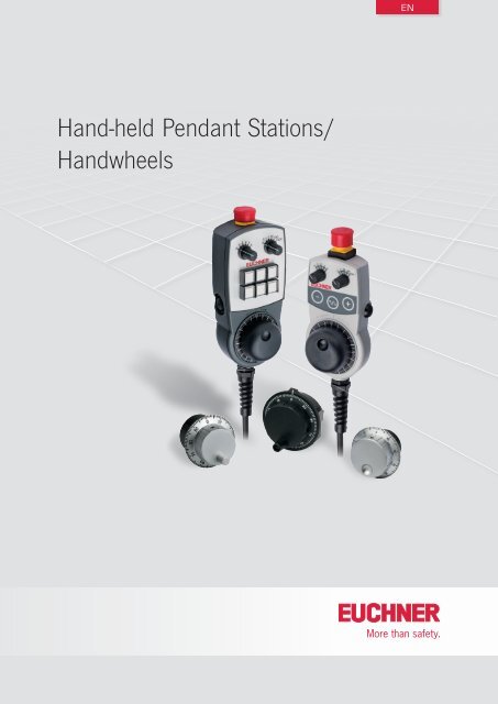
Hand-held Pendant Stations - EUCHNER GmbH + Co. KG
Hand-held Pendant Stations - EUCHNER GmbH + Co. KG
Hand-held Pendant Stations - EUCHNER GmbH + Co. KG
- No tags were found...

You also want an ePaper? Increase the reach of your titles
YUMPU automatically turns print PDFs into web optimized ePapers that Google loves.
GeneralStandards and approvalsStandards<strong>Hand</strong>-<strong>held</strong> pendant stations must comply with the requirements of theEMC directive 2004/108/EC. The EMC directive has been implementedin national law in the EU member states and, as a result, is binding for allmanufacturers. Detailed requirements on EMC are defined in EN 61000(electromagnetic compatibility EMC) part 6-2 and 6-4. If the requirementsof this standard are met, conformity with the applicable laws and thereforewith the EMC directive is assumed. <strong>EUCHNER</strong> hand-<strong>held</strong> pendant stationscomply with the relevant standards and therefore help you to comply withthe requirements during the design of your machinery.ApprovalsMany of the hand-<strong>held</strong> pendant stations given in this catalog are listed byUnderwriters Laboratories (UL). The approval symbols on the individualpages of the catalog indicate which devices are approved.This is the UL approval symbol:Products with this symbol are approvedby Underwriters Laboratories (UL, Canadaand USA)Subject to technical modifications; no responsibility is accepted for the accuracy of this information. Devices supplied may vary slightly from the illustration in the catalog.5
<strong>Hand</strong>-<strong>held</strong> <strong>Pendant</strong> <strong>Stations</strong>Function and technology used in hand-<strong>held</strong> pendant stationsThe most important machine functions can be monitored, e.g. axis selectionand axis movement, can be controlled decentrally using hand-<strong>held</strong>pendant stations. The freedom of movement of the machine operator isincreased, and the operator can monitor and control processes withoutbeing tied to a fixed control panel.In addition to the control function, hand-<strong>held</strong> pendant stations can alsohave a safety function. For this purpose, the hand-<strong>held</strong> pendant stationsare equipped with emergency stop buttons and enabling switches.<strong>Hand</strong>-<strong>held</strong> pendant stations with enabling function<strong>Hand</strong>-<strong>held</strong> pendant stations with enabling function are essentially similarto classic enabling switches.Enabling switches are manually operated control devices that, togetherwith other control switches, enable commands related to potentially hazardousconditions to be run, as long as the enabling switches are actuatedcontinuously. These switches are used wherever personnel must workdirectly in the danger area on machines and systems. This is necessary,e.g. during setting up, programming, testing or servicing work. As perannex 1 of the Machinery Directive, the protective action of movable safetyguards can be disabled in these operating modes. The Machinery Directiveplaces the condition that these operating modes must be secured using alockable device (e.g. key-operated rotary switch) and machine operation isonly allowed to be triggered by a second, separate action. To enable theoperator in the danger area of a machine to trigger a machine movement,an enabling device should also be actuated.The operator must also be able to stop the machine movement usingthe enabling device. This task is performed by the enabling switch. Everyperson who is in the hazardous area must carry an enabling device sothat suitable action can be taken in case of danger.Two-stage or three-stage enabling switch?The operator can only start a machine movement if he/she actuates theenabling device and keeps it in the actuated position. The movement isstopped again when the switch is released. All pushbuttons and all 3-stageenabling switches feature this two-stage function (OFF-ON).However, experience shows that the operator often clenches the enablingdevice in an emergency.In this case a three-stage enabling switch is better and is specificallyrequested in many C standards. This switch has three switch positions(OFF-ON-OFF) and, if the operator clenches the switch, it is actuatedbeyond the enabling position (middle position) and the machine is shutdown as a result.If a 2-stage pushbutton is used, it must also be ensured that, in an emergency,the operator is in a position to activate an emergency stop devicein close proximity (VDI 2853). To identify the type of enabling device inthe catalog, the following symbols are used:Function sequence of two-stage pushbuttonZSG andpushbutton for HBA(2-stage with1 NO contact)ZSG(2-stage with2 NO contacts)NO E1Not actuated<strong>Co</strong>ntactopenclosedclosed, enablingStage 1Not actuatedNO1122NO E1, E2NONot actuatedActuating point2E1E1E22-stage pushbuttonFunction sequence of three-stage enabling switchZXE(3-stage with2 NO contacts)ZSE 2-2(3-stage with2 NO contacts and 1 positivelydriven contact)ZSE 2-4(3-stage with2 NO contactsand 2 positivelydriven contacts)EnablingStage 1Not actuatedE1E2E1E3E2E1E3E2E4ZXE123NO/NC E1, E2NO/NCNot actuated12Stage 2EnablingE1E1E2EnablingStage 2(actuating point)EnablingE1E2E1E3E2E1E3E2E431231 1Actuating point1231E1E2E1E112E3E2E3E2E422Actuating pointStage 3PressedthroughNO/NC12Not actuated1232 2Enabling32123123NCNOZSE 2-2 ZSE 2-4E3E1, E2Not actuatedE3, E4E1, E2NCNOPanic function31 1Actuating point123RestartprotectionNot actuatedNCNOSymbol for a2-stage pushbuttonSymbol for a3-stage enabling switch<strong>Co</strong>ntactopenclosedclosed, enablingEnabling2 23Panic functionRestartprotection3-stage enabling switch6Subject to technical modifications; no responsibility is accepted for the accuracy of this information. Devices supplied may vary slightly from the illustration in the catalog.
<strong>Hand</strong>-<strong>held</strong> <strong>Pendant</strong> <strong>Stations</strong>As can be clearly seen in the figure, the enabling function can only beachieved at stage 2. This function is provided by the closing of the normallyopen contacts (NO = E1 and E2).If the button is released, that is back from stage 2 to stage 1, the normallyopen contacts are opened again. The 2-stage pushbuttons and 3-stageenabling switches are identical in this function.If, in this example, the button on a 3-stage enabling switch is pressedpast the actuating point (stage 2) in panic (to stage 3), then not only thenormally open contacts (NO) are reset, but also the safe positively drivencontacts (NC ) in case of the ZSE series.The patented switch system ensures that the enabling function does notbecome active at stage 2 on the resetting of the pushbutton from stage3 to stage 1. In this example, the enable can only be given if normallyopen and normally closed contacts are closed at the same time. This situationis only possible on actuation from stage 1 to stage 2. In the otherdirection, from stage 3 to stage 1, stage 2 is skipped and unintentionalre-starting prevented.Once the pushbutton has reached stage 1, the function sequence canbe started again.Due to its design, the switch unit also provides a wear-free, constantactuating point (stage 2).Ergonomic housingTo make the operation of machines even easier and safer for the user,<strong>EUCHNER</strong> is the first manufacturer of hand-<strong>held</strong> pendant stations to havedesigned the housing taking into account ergonomic aspects. This meansthe HBA, HBM and HBL housings have been developed such that they fitoptimally in the hand. Well-known manufacturers of machine tools andcontrol systems all over the world are already using <strong>EUCHNER</strong> hand-<strong>held</strong>pendant stations. The wide product range extends from standard housingsto custom-built hand-<strong>held</strong> pendant stations, e.g. with LCD displays,membrane keypads and serial communication ports.<strong>Hand</strong>-<strong>held</strong> pendant stations from <strong>EUCHNER</strong><strong>Hand</strong>-<strong>held</strong> pendant stations from <strong>EUCHNER</strong> are characterized by theirrobust, ergonomic and attractive design. They are used to control axismovements of machines in setup mode, for example. The modular designof every unit permits an individual combination of safety components andfunctions as required by the customer. Depending on the size requiredand the functions to be integrated, <strong>EUCHNER</strong> offers three different typesof hand-<strong>held</strong> pendant stations:ffHBAThe HBA is the smallest and handiest of the hand-<strong>held</strong> pendant stationsfrom <strong>EUCHNER</strong>. Its compact size allows the HBA to be fastened on themachine without taking up much space. Its low weight permits comfortableworking and operation, even over extended periods.ffHBMThe HBM is based on the ergonomic shape of the HBA. It additionally offersmore space and greater flexibility for integrating more componentsand functions.ffHBLThe HBL is the largest hand-<strong>held</strong> pendant station from <strong>EUCHNER</strong>. It isespecially robust and offers maximum flexibility for custom combinationof components, even components with a larger depth.Kits for hand-<strong>held</strong> pendant stationsTo enable you to use ergonomically designed housings even for smallquantities, e.g. prototypes or special versions, <strong>EUCHNER</strong> provides kitsfor hand-<strong>held</strong> pendant stations. As a result you can assemble a hand-<strong>held</strong>pendant station in a user-friendly housing to suit your requirements.Explanation of symbols and notationSymbols and specific notation related to the switches or the switchingcontact are used time and again in the catalog.The following example is intended to explain these aspects:ffNotation 1 NC + 1 NODesign prize for hand-<strong>held</strong> pendant station HBAExplanation:Normally closed contacts are termed NC, normally open contacts NO.The number indicates how many contacts are available. The symbolbehind the NC defines that the NC contact is a positively driven contact.This switch therefore has one normally closed contact and one normallyopen contact; the normally closed contact is a positively driven contact.Custom hand-<strong>held</strong> pendant stationsCustomized hand-<strong>held</strong> pendant stations based on the standard devices canalso be produced in small quantities. In order to use these ergonomicallydesigned housings for the various requirements, <strong>EUCHNER</strong> offers theoption of customized solutions. In the Appendix, you will find forms whichcan be used to describe your requirements. We will be happy to draw upa quotation based on your requirements.Subject to technical modifications; no responsibility is accepted for the accuracy of this information. Devices supplied may vary slightly from the illustration in the catalog.7
XkjVihTgSfRePdcFbEaZYBALKJ<strong>Hand</strong>-<strong>held</strong> <strong>Pendant</strong> <strong>Stations</strong>Ordering tableVersion/itemMembrane keypadFeaturesPushbutton,2-stageEnablingswitch ZXE,3-stageEmergencystopdeviceS4 - S17 S2, S3 S2 S1Order no.HBA-096692 ● ● ● 096692HBA-105693 ● ● ● 105693Circuit planS4 - S17:Membrane keypadS2:Enabling switch*2-stageleftS3:Enabling switch*2-stagerightS2:Enabling switch*ZXE3-stageleftS1:EmergencyStop21231233 2 1S1S17S16S15S14S13S12S11S10S9S8S7S6S5S4S3S2S2B<strong>KG</strong>NBUWHRDYEBNPKRDGNWHPKYEBUBNGYGNBUGYWHYEPKBNYEGNPKYEWHYEGYBNGNGNGYGNWHBKBNPKBKWHGYYEGNBNWHRDBUGYPKRDBUPKBUGYBUmWBNRDRDWHBNBUYEBKVTBKRDBUH17H16H15H14H13H12H11H10H9H8H7H6H5H4DC +24V* Travel diagramsee page 6UNDCMHGSubject to technical modifications; no responsibility is accepted for the accuracy of this information. Devices supplied may vary slightly from the illustration in the catalog.17
<strong>Hand</strong>-<strong>held</strong> <strong>Pendant</strong> <strong>Stations</strong><strong>Hand</strong>-<strong>held</strong> pendant stations HBASffProgrammable pulse generatorffTamper-proof emergency stop deviceaccording to EN ISO 13850,dual-channelffMembrane keypad with 20 keys and2 LEDsffLCD display with LED backgroundlighting, switchable 4-line/8-columnor 8-line/16-columnffRS422 interface, 3964R protocolDimension drawingHBAS-07294985S1HBAS-099105HBAS-09459438,5Depending on version:ff2 pushbuttons, 2-stage, 1 NO contacteach, e.g. for enabling functionff1 enabling switch, 3-stage,2 NO contactsff<strong>Co</strong>iled cable stretchable to 3.5 mffStraight connection cable, length 10 m160S2S3NotesffHolder HBA for hand-<strong>held</strong> pendant stations:see accessories page 58ffAssociated male flange connector, 19-pin:see accessories page 45ffActiveX module available for integrating theuser’s applications (for MS Windows ® -baseduser programs with ActiveX support)2 pushbuttons2-stage, right and left1 enabling switch3-stage, leftMountingmagnetCable lengthstretched3,500 mmCable length10,000 mmPlug connector19-pinCable lengthstretched3,500 mmTechnical dataParameter Value UnitHBA housingMaterialPlastic<strong>Co</strong>lor Gray RAL 7040Operating temperature 0 ... +50 °CStorage temperature -20 ... +50 °CDegree of protection according to EN 60529 / NEMA IP 65 / 250-12<strong>Co</strong>nnection Spiral cable, stretchable to 3.5 m, or straight connection cable, length 10 m.Plug connector, 19-pinWeight Approx. 0.85 kgPulse generatorPulsesprogrammableOutput specificationsRS422AEmergency stop deviceStandard EN ISO 13850Switching elements2 NC contactsUtilization category according to IEC 60947-5-1 DC-13, U e 24 V, I e 3 A A<strong>Co</strong>mmunications interfaceTypeSerial, RS422A (4-wire)Data format8 data bits + 1 parity bit (even), 1 stop bitTransfer speed9600 or 19200 baud, automatic detectionTransfer protocol3964RElectrical connectionPower supply 24 ± 20% V DCOperating current, max. 100 mAPushbutton, 2-stage, e.g. for enabling functionSwitching elements2, one NO contact eachSwitching voltage max. 30 V DCSwitching current max. 100 mAEnabling switch ZXE, 3-stageSwitching elements1, 2 NO contactsUtilization category according to IEC 60947-5-1DC-13, U e 24 V, I e 0.1 A18Subject to technical modifications; no responsibility is accepted for the accuracy of this information. Devices supplied may vary slightly from the illustration in the catalog.
<strong>Hand</strong>-<strong>held</strong> <strong>Pendant</strong> <strong>Stations</strong>Ordering tableFeaturesVersion/item2pushbuttons,2-stage1enabling switchZXE, 3-stageEmergencystop deviceS2, S3 S2 S1Programmable pulse generator,membrane keypad, display,RS422 interface, 3964R protocolOrder no.HBAS-072949HBAS-099105● ● ●072949099105HBAS-094594● ● ● 094594Circuit planS2 (left) + S3 (right):Pushbutton 2 stagee.g. for enabling functionS2:Enablingswitch ZXE3 stageleftS1:Emergency StopKeypadPOWER STATUSDisplay3123ProgrammemoryFLASHMicrocontrollerDisplaymemoryRAMS3S2S21 3 2 E1 E2S1<strong>Co</strong>mmunicationInterface RS422TXTXRXInterfaceRXPulse GeneratorRS422191816141311+24 V0 V15974B3B1AAPowerSupply191817161710865122WHPKBNGYGYWHYEBNWHYEBNGNGNWHGYPKVTVTRDBUP<strong>KG</strong>YYEGNRDBUBNShieldWH* Travel diagramsee page 6ActiveX moduleSoftware for integration into user software that supports ActiveXActiveX module manualDetailed documentation on use of the software093011093013Subject to technical modifications; no responsibility is accepted for the accuracy of this information. Devices supplied may vary slightly from the illustration in the catalog.19
<strong>Hand</strong>-<strong>held</strong> <strong>Pendant</strong> <strong>Stations</strong><strong>Hand</strong>-<strong>held</strong> pendant station HBM-111711ff<strong>Hand</strong>wheel 100 pulses, wear-freemagnetic detent mechanismffTamper-proof emergency stop deviceaccording to EN ISO 13850,dual-channelff1 enabling switch, 3-stage,2 NO contactsff2 selector switches, 6 positions each(X, Y, Z, 4, 5, 6 and 0, 0.1, 1, 10, 100,1000)ff6 illuminated pushbuttons, can be individuallylabeledff<strong>Co</strong>iled cable, stretchable to 3.5 m,35-core, flying leadDimension drawingS36 positions200S5S892 S1S6S9S7S10S46 positionsMounting magnetS2Enabling switch3-stage, leftMounting magnetA1700NotesffHolder HBM for hand-<strong>held</strong> pendant stations:see accessories page 58(cable length stretched)3500550 - 2500Technical dataParameter Value UnitHBM housingMaterialPlastic<strong>Co</strong>lorAnthraciteOperating temperature 0 ... +50 °CStorage temperature -20 ... +50 °CDegree of protection according to EN 60529 / NEMA IP 65 / 250-12<strong>Co</strong>nnection<strong>Co</strong>iled cable, stretchable to 3.5 m, 35-core, flying leadWeight Approx. 1.1 kg<strong>Hand</strong>wheelPulses/revolution 100Power supply 5 ± 5% V DCOutput specificationsRS422AEmergency stop deviceStandard EN ISO 13850Switching elements2 NC contactsUtilization category according to IEC 60947-5-1 DC-13, U e 24 V, I e 3 A AEnabling switch ZXE, 3-stageSwitching elements1, 2 NO contactsUtilization category according to IEC 60947-5-1DC-13, U e 24 V, I e 0.1 ASelector switchOutput codesee circuit planSwitching voltage max. 25 V AC/DCBreaking capacity max. 0.2 VAButtonsSwitching elements3, one NO contact eachSwitching voltage max. 30 V DCSwitching current max. 100 mALEDI = 21 mA / U = 24 V DC20Subject to technical modifications; no responsibility is accepted for the accuracy of this information. Devices supplied may vary slightly from the illustration in the catalog.
<strong>Hand</strong>-<strong>held</strong> <strong>Pendant</strong> <strong>Stations</strong>Ordering tableItem<strong>Hand</strong>-<strong>held</strong> pendant station HBM-111711 with:ff<strong>Hand</strong>wheel 100 pulsesffTamper-proof emergency stop device according to EN ISO 13850, dual-channelffEnabling switch ZXE, 3-stage, 2 NO contacts,ff2 selector switches, 6 positions eachff6 illuminated pushbuttons, 1 NO contact eachOrder no.111711Circuit planS4 DCBA1 0000 02 0001 0,13 0011 14 0010 105 0110 1006 0111 1000S3 DCBA1 0000 X2 0001 YZ4563 00114 00105 01106 01113123S10Buttonwith whiteLEDS9Buttonwith whiteLEDS8Buttonwith whiteLEDS7Buttonwith whiteLEDS6Buttonwith whiteLEDS5Buttonwith whiteLEDS4Right selectorswitch6 positionsS3Left selectorswitch6 positionsS2Left enabling switchZXE *S1EMERGENCYSTOPA1<strong>Hand</strong>wheel, 100 pulsesRS422 AA0522.5°22.5°1BBAA2434343434343616144333E1E22211RS422 AX2X1X2X1X2X1X2X1X2X1X2X1ZZGRAYD C BAZZGRAYD C BAScreenB<strong>KG</strong>NGNPKRDYEYEGYRDGNGNGYYEBUBKBNGNBUBKWHYEPKRDWHBNRDBNBUBUWHBNP<strong>KG</strong>YPKWHPKBNGYGYWHBNYEYEWHBNGNGNWHRDBUVTBKRDBUP<strong>KG</strong>YYEGNBNWH0 VLP6LP5LP4LP3LP1LP2LP6+24 VLP5LP4LP3LP1LP2NO1NO2C2C1X1/4 BX1/3 BX1/2 AX1/1 AX1/5+UB: DC+5V +/-5%X1/6 0V* Travel diagramsee page 6Subject to technical modifications; no responsibility is accepted for the accuracy of this information. Devices supplied may vary slightly from the illustration in the catalog.21
<strong>Hand</strong>-<strong>held</strong> <strong>Pendant</strong> <strong>Stations</strong><strong>Hand</strong>-<strong>held</strong> pendant station HBM-112392ff<strong>Hand</strong>wheel 100 pulses, wear-freemagnetic detent mechanismffTamper-proof emergency stop deviceaccording to EN ISO 13850,dual-channelff1 enabling switch, 3-stage,2 NO contactsff9 illuminated foil pushbuttons, 1 NOcontact each, can be labeled asrequired using slide-in stripsffStraight connection cable, length3.5 m, plug connector 35-pinDimension drawing200S1S3S4S6S7S992S5S8Exchangeable slide-in stripsS11S10Mounting magnetS2Enabling switch3-stage, leftMounting magnet82A13500NotesffHolder HBM for hand-<strong>held</strong> pendant stations:see accessories page 58ffAssociated flange connector, 35-pin:see connection components page 51ffFor template for slide-in strips, seewww.euchner.de (Support)ffReplacement for hand-<strong>held</strong> pendant stationsHBE-097337 and HBE-097338Plug connector35-pinTechnical dataParameter Value UnitHBM housingMaterialPlastic<strong>Co</strong>lorAnthraciteOperating temperature 0 ... +50 °CStorage temperature -20 ... +50 °CDegree of protection according to EN 60529 / NEMA IP 65 / 250-12<strong>Co</strong>nnectionStraight connection cable, length 3.5 m, plug connector 35-pinWeight Approx. 1.1 kg<strong>Hand</strong>wheelPulses/revolution 100Power supply 5 ± 5% V DCOutput specificationsRS422AEmergency stop deviceStandard EN ISO 13850Switching elements2 NC contactsUtilization category according to IEC 60947-5-1 DC-13, U e 24 V, I e 3 A AEnabling switch ZXE, 3-stageSwitching elements1, 2 NO contactsUtilization category according to IEC 60947-5-1DC-13, U e 24 V, I e 0.1 AMembrane keypadSwitching elements14, one NO contact eachSwitching voltage max. 30 V DCSwitching current max. 100 mABreaking capacity max. 1 W22Subject to technical modifications; no responsibility is accepted for the accuracy of this information. Devices supplied may vary slightly from the illustration in the catalog.
<strong>Hand</strong>-<strong>held</strong> <strong>Pendant</strong> <strong>Stations</strong>X5/4 X3/10X7/4X5/3X3/9X7/3X5/2X3/8X7/2X5/1X3/7X7/1X4/6X3/6X6/6X4/5X3/5X6/5X4/4X3/4X6/4X4/3X3/3X6/3X4/2X3/2X6/2X3/1NO1NO224 V0 VmZYhXgUTeSdNcMbJaHGkLKVPRWFEDCBAScreenB<strong>KG</strong>NBNRDRDYERDWHRDGNBNBUYEBUBUWHGNBUBNPKYEPKWHP<strong>KG</strong>NPKBNGYYEGYGYWHGNGYBNYEBKBNBKWHGYPKX6/1X4/1ifjOrdering tableItem<strong>Hand</strong>-<strong>held</strong> pendant station HBM-112392 with:ff<strong>Hand</strong>wheel 100 pulsesffTamper-proof emergency stop device according to EN ISO 13850, dual-channelffEnabling switch ZXE, 3-stage, 2 NO contacts,ff9 illuminated foil pushbuttons, 1 NO contact eachffSlide-in strips for logoOrder no.112392Circuit plan3123S3 - S11Buttons with LEDS11 S10 S9 S8 S7 S6 S5 S4 S3S2Left enabling switchZXE *S1EMERGENCYSTOPA1<strong>Hand</strong>wheel, 100 pulsesRS422 AA0512BBAA4 3 4 3 4 3 4 3 4 3 4 3 4 3 4 3 4 3433E12143E221RS422 AYEWHBNGNGNWHRDBUVTBKRDBUP<strong>KG</strong>YYEGNBNWHC2C1X1/4 BX1/3 BX1/2 AX1/1 AX1/5+UB: DC+5V +/-5%X1/60V* Travel diagramsee page 6Subject to technical modifications; no responsibility is accepted for the accuracy of this information. Devices supplied may vary slightly from the illustration in the catalog.23
<strong>Hand</strong>-<strong>held</strong> <strong>Pendant</strong> <strong>Stations</strong><strong>Hand</strong>-<strong>held</strong> pendant station HBL-097339ff<strong>Hand</strong>wheel 100 pulsesffTamper-proof emergency stop deviceaccording to EN ISO 13850,dual-channelffEnabling switch, 3-stageff3 illuminated pushbuttons, can beindividually labeledff2 selector switchesffKey-operated rotary switchDimension drawing114S7S677120Hanging clipS3S4S5Mounting magnetL1 L2 L3252S8Enabling switch3-stage, leftS112 positionsS23 positionsA1NotesffHolder HBL for hand-<strong>held</strong> pendant stations:see accessories page 58ffAssociated flange connector, 35-pin:see connection components page 51Cable length3,500 mmPlug connector35-pinTechnical dataParameter Value UnitHousing HBLMaterialPlastic<strong>Co</strong>lor Blue-gray RAL 7031Ambient temperature 0 ... +55 °CDegree of protection according to EN 60529 IP 65<strong>Co</strong>nnectionCable 3.5 m, 35-pin plugWeight Approx. 2.1 kgEmergency stop deviceStandard EN ISO 13850Switching elements2 NC contactsUtilization category according to IEC 60947-5-1DC-13 U e 24 V I e 2,75 A<strong>Hand</strong>wheel HKDPulses per revolution 100Power supply 5 ± 5% V DCOutput circuitRS 422 AOutput signals see page 67Enabling switch ZSE, 3-stageSwitching elements2 NO contacts, 1 positively driven contactUtilization category according to IEC 60947-5-1AC-15 U e 24 V I e 4 ADC-13 U e 24 V I e 3 AButtonsSwitching elements3, one NO contact eachSwitching voltage max. 30 V DCSwitching current max. 100 mALEDI = 21 mA / U = 24 V DCSelector switchSwitching voltage max. 30 V DCSwitching current max. 100 mAKey-operated rotary switchSwitching voltage max. 30 V AC/DCSwitching current max. 250 mA24Subject to technical modifications; no responsibility is accepted for the accuracy of this information. Devices supplied may vary slightly from the illustration in the catalog.
<strong>Hand</strong>-<strong>held</strong> <strong>Pendant</strong> <strong>Stations</strong>Ordering tableItem<strong>Hand</strong>-<strong>held</strong> pendant station HBL-097339 with:ff<strong>Hand</strong>wheel 100 pulsesffTamper-proof emergency stop device according to EN ISO 13850, dual-channelffEnabling switch ZSE, 3-stage, 2 NO contacts, 1 positively driven contactff3 illuminated pushbuttons, 1 NO contact eachff2 selector switches, 12 positions and 3 positionsffKey-operated rotary switch, 1 NO contact, 1 NC contactOrder no.097339Circuit planEmergency stopS7Key-operatedrotary switchSelector switchOutput code1 of 3Enabling switch ZSE *S6 S2 S83123L1 L2 L3A k m B H S T U i j c b aP R V W L KS3S5AS4ZSelector switchOutput codebinaryDC1S1BG J M N e f g h12Gray-<strong>Co</strong>deA1<strong>Hand</strong>wheelAABBX Y C D E FOutput tableSelector switch S1Detent Outputposition D C B A1 0 0 0 02 0 0 0 13 0 0 1 04 0 0 1 15 0 1 0 06 0 1 0 17 0 1 1 08 0 1 1 19 1 0 0 010 1 0 0 111 1 0 1 012 1 0 1 1* Travel diagramsee page 6Subject to technical modifications; no responsibility is accepted for the accuracy of this information. Devices supplied may vary slightly from the illustration in the catalog.25
<strong>Hand</strong>-<strong>held</strong> <strong>Pendant</strong> <strong>Stations</strong><strong>Hand</strong>-<strong>held</strong> pendant station HBLS-072725ff<strong>Hand</strong>wheel 100 pulsesffTamper-proof emergency stop deviceaccording to EN ISO 13850,dual-channelff2 pushbuttons, 2-stage, e.g. forenabling functionffKeypad with 12 illuminated keysffKeypad can be designed as requiredusing slide-in filmff2 selector switchesffLCD display (text mode)ffRS422 interface, 3964R protocolDimension drawing114S1Display, 8 lines,15 characters/lineHanging clip77120Mounting magnet252S2/S3Pushbutton2-stage,left/rightA1NotesffHolder HBL for hand-<strong>held</strong> pendant stations:see accessories page 58ffAssociated flange connector, 23-pin:see connection components page 51ffActiveX module available for integrating theuser’s applications (for MS Windows ® -baseduser programs with ActiveX support)Cable length3,500 mmPlug connector23-pinTechnical dataParameter Value UnitHousing HBLMaterialPlastic<strong>Co</strong>lor Blue-gray RAL 7031Operating temperature 0 ... +50 °CDegree of protection according to EN 60529 IP 65<strong>Co</strong>nnectionCable 3.5 m, 23-pin plugWeight 2.2 kgEmergency stop deviceStandard EN ISO 13850Switching elements2 NC contactsUtilization category according to IEC 60947-5-1DC-13 U e 24 V I e 2.75 A<strong>Hand</strong>wheel HKDPulses per revolution 100Output circuitRS 422 AOutput signals see page 67Pushbutton ZSG, 2-stage, e.g. for enabling functionSwitching elements2, one NO contact eachUtilization category according to IEC 60947-5-1AC-15 U e 24 V I e 4 ADC-13 U e 24 V I e 3 AInterfaceType RS 422Data format8 data bits , even parity, 1 or 2 stop bitsTransfer speed 9600 or 19200 (setting using DIL switches) baudTransfer protocol3964 RElectrical connectionPower supply 24 ±20% V DCOperating current, max. 200 mA26Subject to technical modifications; no responsibility is accepted for the accuracy of this information. Devices supplied may vary slightly from the illustration in the catalog.
<strong>Hand</strong>-<strong>held</strong> <strong>Pendant</strong> <strong>Stations</strong>Ordering tableItem<strong>Hand</strong>-<strong>held</strong> pendant station HBLS-072725 with:ff<strong>Hand</strong>wheel 100 pulsesffTamper-proof emergency stop device according to EN ISO 13850, dual-channelff2 pushbuttons ZSG 2-stage, 2 NO contacts each, e.g. for enabling functionffKeypad with 12 illuminated keysff2 selector switches, 12 positions eachOrder no.072725Circuit planA1AABB<strong>Hand</strong>wheel A05 ( RS422A)A A B BPowersupplyMicrocontrollerSerialcommunication interfaceRS422RX NRX TX NTXPushbutton ZSG *e.g. for enabling functionS2leftrightS3212+UB 0 Volt<strong>Co</strong>ntrol PanelS1E-Stop8 6 1 5 9 10 3 2 7 4C D E F A B J M N S V G H W L R K PShield electr. connected to the plug connector housingShield* Travel diagramsee page 6ActiveX moduleSoftware for integration into user software that supports ActiveXActiveX module manualDetailed documentation on use of the software067176067178Subject to technical modifications; no responsibility is accepted for the accuracy of this information. Devices supplied may vary slightly from the illustration in the catalog.27
<strong>Hand</strong>-<strong>held</strong> <strong>Pendant</strong> <strong>Stations</strong>28Subject to technical modifications; no responsibility is accepted for the accuracy of this information. Devices supplied may vary slightly from the illustration in the catalog.
<strong>Hand</strong>-<strong>held</strong> <strong>Pendant</strong> Station HBA Kit<strong>Hand</strong>-<strong>held</strong> pendant station HBA kitThe kit is designed to match individual customer specifications. Thanksto its modular configuration, you can construct prototypes and specialversions in line with your requirements. To match the housings, aluminumfront panels are available in silver or black anodized.Customer-specific functionality can be achieved by using the componentssupplied in the kit (pushbutton, selector switch, key-operated rotary switch,handwheel, enabling switch, etc). For connection to the control system,cables with different numbers of wires, plug connectors and the relevantflange sockets are available. The type of protection IP 65 can be achievedusing one of the seals included.HBA kit without handwheelThe versions without handwheel have a cable gland and mountingmagnet. In addition to the basic HBA housing, other identical versionswith the option of fitting an emergency stop device and 2-stage pushbuttonsor 3-stage enabling switches are available.HBA kit with handwheelThe versions with handwheels, some with 2-stage pushbutton or3-stage enabling switch, are distinguished by the output stages of thehandwheels and are adapted to various control systems.Subject to technical modifications; no responsibility is accepted for the accuracy of this information. Devices supplied may vary slightly from the illustration in the catalog.29
<strong>Hand</strong>-<strong>held</strong> <strong>Pendant</strong> Station HBA KitHBA housing without handwheelffCable gland for cable diameter5‐10 mmffRubber-coated mounting magnet onthe rear of housingff6 fixing domes for printed circuit boardinstallation in top shellDepending on version:ffHole for emergency stop device(sealed with blind plug)ff2 pushbuttons, 2-stage, 1 NO contacteach, e.g. for enabling functionff1 enabling switch, 3-stage,2 NO contactsDimension drawingS1HousingHBA-084450HBA-086155∅ 85S2HousingHBA-095562Blind plug in holefor emergency stop device38,5Mounting magnetNotesffSuitable front panels see page 36ffSuitable emergency stop device (turn or pullto reset) see page 54ffAttention: Housing HBA-095562 is suitableonly for emergency stop device 106435 withshort design.ffDepending on version with 2 2-stage pushbuttonsor 1 3-stage enabling switch.160Enabling switch,3-stageCable glandincludedTopshellDimensions of emergency stop devices see page 54Technical dataParameter Value UnitHBA housingMaterialPlastic<strong>Co</strong>lor Gray RAL 7040Operating temperature 0 ... +50 °CStorage temperature -20 ... +50 °CDegree of protection according to EN 60529 / NEMA IP 65 / 250-12Weight 0.3 kgPushbutton, 2-stage, e.g. for enabling functionSwitching elements2, one NO contact each<strong>Co</strong>nnection ratingsDC 30 V / 100 mAEnabling switch ZXE, 3-stageSwitching elements2 NO contactsUtilization category according to IEC 60947-5-1DC-13, U e 24 V, I e 0.1 A30Subject to technical modifications; no responsibility is accepted for the accuracy of this information. Devices supplied may vary slightly from the illustration in the catalog.
<strong>Hand</strong>-<strong>held</strong> <strong>Pendant</strong> Station HBA KitOrdering tableFeaturesVersion/itemHole foremergency stop device2 pushbuttons *2-stage, pre-assembled with1 NO contact each,e.g. for enabling function1 enabling switch ZXE **3-stage,2 NO contactspre-assembledOrder no.S1, S2 S1Housing HBA-084445(without hole, without enabling switch)084445Housing HBA-084450●for emergency stopshort and long designs084450Housing HBA-086155Housing HBA-095562●for emergency stopshort and long designs●for emergency stopshort design● 086155● 0955622123123* Travel diagram see page 6** Travel diagram see page 55Subject to technical modifications; no responsibility is accepted for the accuracy of this information. Devices supplied may vary slightly from the illustration in the catalog.31
<strong>Hand</strong>-<strong>held</strong> <strong>Pendant</strong> Station HBA KitHBA housing with handwheelff<strong>Hand</strong>wheel 100 or 25 pulses, wear-freemagnetic detent mechanismffHole for emergency stop device(sealed with blind plug)ffCable gland for cable diameter5‐10 mmffRubber-coated mounting magnet onthe rear of housingff6 fixing domes for printed circuit boardinstallation in top shellDimension drawing∅ 85Blind plug in holefor emergency stop device67Depending on version:ff2 pushbuttons, 2-stage, 1 NO contacteach, e.g. for enabling functionff1 enabling switch, 3-stage,2 NO contactsffVarious handwheel output stagesS1S2Mounting magnetNotesffSuitable front panels see page 36ffSuitable emergency stop device (turn or pullto reset) see page 54ffAttention:f fHousings HBA‐095561, HBA‐095573,HBA‐095572 and HBA‐095574 suitable onlyfor emergency stop device 106435 shortdesign.ffDepending on version with 2 two-stage pushbuttonsor 1 three-stage enabling switch.160Enabling switch3-stageA1Cable glandincludedTopshellDimensions of emergency stop devices see page 54Technical dataParameter Value UnitHBA housingMaterialPlastic<strong>Co</strong>lor Gray RAL 7040Operating temperature 0 ... +50 °CStorage temperature -20 ... +50 °CDegree of protection according to EN 60529 /NEMA IP 65 / 250-12Weight 0.3 kgPushbutton, 2-stage, e.g. for enabling functionSwitching elements2, one NO contact each<strong>Co</strong>nnection ratings30 V DC / 100 mAEnabling switch ZXE, 3-stageSwitching elements1, 2 NO contactsUtilization category according to IEC 60947-5-1DC-13, U e 24 V, I e 0.1 A<strong>Hand</strong>wheel RS422A (U B = 5 V DC)Pulses/revolution 100Power supply 5 ± 5% V DCOutput specificationsRS422A<strong>Hand</strong>wheel push-pull 5 V (U B = 5 V DC)Pulses/revolution 100Power supply 5 ± 5% V DCOutput circuit5 V push-pullOutput voltage / output current HIGH, min. 4.0 V at 0 mA / 3.4 V at 5 mA / 3.0 V at 20 mALOW, max.1.3 V at 15 mA<strong>Hand</strong>wheel push-pull 5 V (U B = 10...30 V DC)Pulses/revolution 25Power supply 10 ... 30 V DCOutput circuit5 V push-pullOutput voltage / output current HIGH, min. 4.9 V at 0 mA / 3.9 V at 5 mA / 3.6 V at 20 mALOW, max.1.3 V at 15 mA<strong>Hand</strong>wheel push-pull 24 V (U B = 10...30 V DC)Pulses/revolution 100Power supply 10 ... 30 V DCOutput circuit24 V push-pullOutput voltage / output current HIGH, min. U B - 3 V at 20 mALOW, max.3 V at 20 mA32Subject to technical modifications; no responsibility is accepted for the accuracy of this information. Devices supplied may vary slightly from the illustration in the catalog.
<strong>Hand</strong>-<strong>held</strong> <strong>Pendant</strong> Station HBA KitOrdering tableVersion/itemHousingHBA-083449HousingHBA-095561HousingHBA-083499HousingHBA-095573HousingHBA-083495HousingHBA-095572HousingHBA-086762HousingHBA-095574RS422●A05●A05Output stagePush-pull<strong>Hand</strong>wheelPowersupplyFeaturesPulses perrevolutionHole foremergencystop2pushbuttons *2-stage,1 NO contacteachpre-assembled1 enablingswitch **ZXE, 3-stage,2 NO contactspre-assembledOrder no.U A U B S1, S2 S1●5 V DC 100for emergencystop ● 083449short and longdesigns●5 V DC 100for emergencystop● 095561short design●5 VG12●5 VG12●U B - 3 VG24●U B - 3 VG24●5 VG05●5 VG0510 ... 30 V DC 2510 ... 30 V DC 2510 ... 30 V DC 10010 ... 30 V DC 1005 V DC 1005 V DC 100●for emergencystopshort and longdesigns●for emergencystopshort design●for emergencystopshort and longdesigns●for emergencystopshort design●for emergencystopshort and longdesigns●for emergencystopshort design● 083499● 095573● 083495● 095572● 086762● 095574A1<strong>Hand</strong>wheelRS422AA1<strong>Hand</strong>wheelpush pull-+Shield-+Shield-A+A0 VUBA-+A0 VUB2123123/ABRS 422 A/ABBpush pullB/B/B* Travel diagram see page 6** Travel diagram see page 55Subject to technical modifications; no responsibility is accepted for the accuracy of this information. Devices supplied may vary slightly from the illustration in the catalog.33
<strong>Hand</strong>-<strong>held</strong> <strong>Pendant</strong> Station HBA KitTop shell HBAffMaterial plasticff<strong>Co</strong>lor gray or blackDepending on version:ffHole for handwheel HKBDimension drawingTop shellHBA-105640HBA-105642Top shellHBA-105641HBA-105643NotesffSuitable front panels see page 36 52A85Fixing dome(rear side)A8552Fixing dome(rear side)3,5715,0515592,59315546,592,546,5AA13,6Hole forhandwheel HKB(handwheel HKBsee page 62)3A-AOrdering tableItemOrder no.Top shell HBA-105640, gray, without hole for handwheel HKB 105640Top shell HBA-105641, gray, with hole for handwheel HKB 105641Top shell HBA-105642, black, without hole for handwheel HKB 105642Top shell HBA-105643, black, with hole for handwheel HKB 10564334Subject to technical modifications; no responsibility is accepted for the accuracy of this information. Devices supplied may vary slightly from the illustration in the catalog.
<strong>Hand</strong>-<strong>held</strong> <strong>Pendant</strong> Station HBA KitBottom shell HBAffMaterial plasticff<strong>Co</strong>lor gray or blackDimension drawing8532,522,4Depending on version:ffHole for emergency stop deviceffHole for enabling switch ZXE(3-stage, 2 NO contacts)ff2 pushbuttons, 2-stage, 1 NO contacteach, e.g. for enabling function5018,5NotesffSuitable emergency stop device (turn or pullto reset) see page 54ffSuitable enabling switch ZXE (3-stage, 2 NOcontacts) see page 55ffTechnical data of pushbutton see page 481605570A25Pushbutton(optional)Mounting magnet5Mounting screws(6 x included)+0,2016,2 - 0,12Cable gland(included)A20,515Hole foremergency stop(optional)Hole forenabling switch ZXE(optional)Enabling switch ZXE,see page 5522,5Ordering tableVersion/itemBottom shell HBA-105503, color gray(without holes, without pushbutton)Bottom shell HBA-105504, color grayBottom shell HBA-114213, color grayBottom shell HBA-105506, color grayBottom shell HBA-105507, color black(without holes, without pushbutton)Bottom shell HBA-105508, color blackBottom shell HBA-114215, color blackBottom shell HBA-105510, color blackHole foremergency stop device●for emergency stopshort and long designs●for emergency stopshort and long designs●for emergency stopshort design●for emergency stopshort and long designs●for emergency stopshort and long designs●for emergency stopshort designFeatures2 pushbuttons, * 1 enabling switch ZXE, **2-stage, 1 NO contact each3-stage,pre-assembled,2 NO contactse.g. for enabling function pre-assembledS1, S2 S1Order no.105503105504● 114213● 105506105507105508● 114215● 1055102123123* Travel diagram see page 6** Travel diagram see page 55Subject to technical modifications; no responsibility is accepted for the accuracy of this information. Devices supplied may vary slightly from the illustration in the catalog.35
<strong>Hand</strong>-<strong>held</strong> <strong>Pendant</strong> Station HBA KitFront panels for housing and top shell HBA with and without handwheelNotesffSuitable for housing HBA (see page 30 and page32) and top shell HBA (see page 34)Dimension drawingFor housing HBAwithout handwheel69,40,5∅ 67,40,563,9142,4Rear is coated soas to be self-adhesiveFor housing HBAwith handwheel69,4Rear is coated soas to be self-adhesiveTechnical dataParameter Value UnitFront-panel materialElectrically anodized aluminum, black or silver, rear side with self-adhesive coatingOrdering tableItemOrder no.Front panel for housing HBA without handwheel, silver anodized 084395Front panel for housing HBA without handwheel, black anodized 084396Front panel for housing HBA with handwheel, silver anodized 083635Front panel for housing HBA with handwheel, black anodized 08363636Subject to technical modifications; no responsibility is accepted for the accuracy of this information. Devices supplied may vary slightly from the illustration in the catalog.
<strong>Hand</strong>-<strong>held</strong> <strong>Pendant</strong> <strong>Stations</strong> HBM Kit<strong>Hand</strong>-<strong>held</strong> pendant stations HBM kitThe kit is designed to match individual customer specifications. Thanksto its modular configuration, you can construct prototypes and specialversions in line with your requirements. To match the housings, aluminumfront panels are available in silver or black anodized.Customer-specific functionality can be achieved by using the componentssupplied in the kit (pushbutton, selector switch, key-operated switch,handwheel, enabling switch, KE joystick, etc). For connection to the controlsystem, cables with different numbers of wires, plug connectors and therelevant flange sockets are available. The type of protection IP 65 can beachieved using one of the seals included.<strong>Hand</strong>-<strong>held</strong> pendant stations HBM kitSubject to technical modifications; no responsibility is accepted for the accuracy of this information. Devices supplied may vary slightly from the illustration in the catalog.37
<strong>Hand</strong>-<strong>held</strong> <strong>Pendant</strong> <strong>Stations</strong> HBM KitTop shell HBMffMaterial plasticff<strong>Co</strong>lor anthraciteDimension drawingDepending on version:ffHole for handwheel HKBNotesffSuitable front panels see page 40Top shellHBM-112991A92Top shellHBM-112986A92SealA-A1951955,5315,05AA13,6Hole forhandwheel HKB(handwheel HKBsee page 62)7Ordering tableItemOrder no.Top shell HBM-112991 without hole for handwheel HKB 112991Top shell HBM-112986 with hole for handwheel HKB 11298638Subject to technical modifications; no responsibility is accepted for the accuracy of this information. Devices supplied may vary slightly from the illustration in the catalog.
<strong>Hand</strong>-<strong>held</strong> <strong>Pendant</strong> <strong>Stations</strong> HBM KitBottom shell HBMffMaterial plasticff<strong>Co</strong>lor anthraciteDimension drawingDepending on version:ffHole for emergency stop device(sealed with blind plug)ffHole for enabling switch ZXE(3-stage, 2 NO contacts)ff2 pushbuttons, 2-stage, 1 NO contacteach, e.g. for enabling function92644440Version withemergency stop deviceand 2 pushbuttons4837,4325NotesffSuitable emergency stop device (turn or pullto reset) see page 54ffSuitable enabling switch ZXE (3-stage, 2 NOcontacts) see page 55ffTechnical data of pushbutton see page 483 x 40 (= 120)40762162,522,527,5195Pushbutton (optional)Cable gland (included)4766,5Hole foremergency stopwith blind plug(optional)Version withemergency stop deviceand enabling switch ZXEMounting magnet22Hole forenabling switch ZXE(optional)Enabling switch ZXEsee page 55Mounting screws(8 x included)Mounting screws(8 x included)Cable gland (included)Ordering tableVersion/itemHole foremergency stop deviceFeatures2 pushbuttons, *2-stage, 1 NO contact eachHole forpre-assembled,enabling switch ZXE **e.g. for enabling functionS1, S2 S1Order no.Bottom shell HBM-112949(without holes, without pushbutton)112949Bottom shell HBM-112954 ● 112954Bottom shell HBM-112958 ● ● 112958Bottom shell HBM-112955 ● ● 1129552123123* Travel diagram see page 6** Travel diagram see page 55Subject to technical modifications; no responsibility is accepted for the accuracy of this information. Devices supplied may vary slightly from the illustration in the catalog.39
<strong>Hand</strong>-<strong>held</strong> <strong>Pendant</strong> <strong>Stations</strong> HBM KitFront panels for top shell HBM with and without handwheelNotesffSuitable for top shell HBM (see page 38)Dimension drawing87,4For top shell HBMwithout handwheel(182,4)Material thickness 0.5 mm67,4Rear is coated soas to be self-adhesiveFor top shell HBMwith handwheel106,4Material thickness 0.5 mm87,4Rear is coated soas to be self-adhesiveTechnical dataParameter Value UnitFront-panel materialElectrically anodized aluminum, black or silver, rear side with self-adhesive coatingOrdering tableItemOrder no.Front panel for top shell HBM without handwheel, silver anodized 113060Front panel for top shell HBM without handwheel, black anodized 113438Front panel for top shell HBM with handwheel, silver anodized 113061Front panel for top shell HBM with handwheel, black anodized 11344040Subject to technical modifications; no responsibility is accepted for the accuracy of this information. Devices supplied may vary slightly from the illustration in the catalog.
<strong>Hand</strong>-<strong>held</strong> <strong>Pendant</strong> <strong>Stations</strong> HBL Kit<strong>Hand</strong>-<strong>held</strong> pendant stations HBL kitThe kit is designed to match individual customer specifications. Thanksto its modular configuration, you can construct prototypes and specialversions in line with your requirements. The HBL housings are shaped differently,depending on the safety components to be integrated. Dependingon the version, front panels are available for use with or without handwheel.Customer-specific functionality can be achieved by using the componentssupplied in the kit (pushbutton, selector switch, enabling switch, handwheel,key-operated rotary switch, KE joystick, etc). The type of protection IP65 can be achieved using an included seal. For connection to the controlsystem, cables with different numbers of wires, plug connectors and therelevant flange sockets are available.<strong>Hand</strong>-<strong>held</strong> pendant stations HBL kitSubject to technical modifications; no responsibility is accepted for the accuracy of this information. Devices supplied may vary slightly from the illustration in the catalog.41
<strong>Hand</strong>-<strong>held</strong> <strong>Pendant</strong> <strong>Stations</strong> HBL KitHousing HBLffRubber-coated mounting magnet onthe rear of housingffHanging clipff6 screws for front panel fasteningff<strong>Co</strong>ver frame for front panelffFixing domes for printed circuit boardinstallationDimension drawingDepending on version:ffFastening nut for cable gland Pg 11or Pg 13.5ffHole for emergency stop deviceff2 pushbuttons ZSG, 2-stage,2 NO contacts each, e.g. for enablingfunctionffHole on left for enabling switch ZSENotesffEmergency stop devices see page 56ffEnabling switch ZSE see page 57ffCable glands see page 53ffAssembly drawings see page 75ffPg 11 for cable diameter 5 ... 10 mmffPg 13.5 for cable diameter 6 ... 12 mmPushbutton ZSGon both sidesScrew-in depthmax. 6.0(applies to allmounting holes)View AHanging clipMounting magnetHole forenabling switch ZSE2-4∅ DATechnical dataParameter Value UnitHousing HBLMaterialPlastic<strong>Co</strong>lor Blue-gray RAL 7031Ambient temperature 0 ... +55 °CDegree of protection according to EN 60529 / NEMA IP 65 / 250-12Pushbutton ZSG, 2-stage, e.g. for enabling functionSwitching elements2, 2 NO contacts eachUtilization category according to IEC 947-5-1AC-15 U e 24 V I e 4 ADC-13 U e 24 V I e 3 A42Subject to technical modifications; no responsibility is accepted for the accuracy of this information. Devices supplied may vary slightly from the illustration in the catalog.
<strong>Hand</strong>-<strong>held</strong> <strong>Pendant</strong> <strong>Stations</strong> HBL KitOrdering tableFeaturesVersion/itemFixing nutfor cable gland(cable glandsee page 53)Pg 11 Pg 13.5Hole foremergency stop *(emergency stopsee page 56)Hole forenabling switchZSE2-2 C1692,3-stage2 NO + 1 NC(enabling switch page 57)Hole forenabling switchZSE2-4 C1943,3-stage2 NO + 2 NC(enabling switch page 57)2 pushbuttonsZSG, 2-stage,2 NO contacts eachpre-assembled,e.g. for enabling functionOrder no.HousingHBL-073098● 073098HousingHBL-072630● ● 072630HousingHBL-073113● ● ● 073113HousingHBL-072631● ● 072631HousingHBL-073109● ● 073109HousingHBL-072632● ● 072632HousingHBL-072983● ● ● 072983HousingHBL-083484● ● ● 083484* Blind plug ∅ 22 for emergency stop device hole includedSubject to technical modifications; no responsibility is accepted for the accuracy of this information. Devices supplied may vary slightly from the illustration in the catalog.43
<strong>Hand</strong>-<strong>held</strong> <strong>Pendant</strong> <strong>Stations</strong> HBL KitFront panel for housing HBLDimension drawingFront-panelflat sealFlat sealFront panelwith hole forhandwheel mountingFront panelwithout hole forhandwheel mountingFront panel13Mounting holefor handwheelHKD(handwheel HKDsee page 66)Technical dataParameter Value UnitFront-panel materialElectrically anodized aluminum, black, NBR, self-adhesive on one sideOrdering tableItemOrder no.HBL front panel, with seal 073138HBL front panel, with hole for handwheel HKD and seal 073139Front seal for HBL front panel 07264144Subject to technical modifications; no responsibility is accepted for the accuracy of this information. Devices supplied may vary slightly from the illustration in the catalog.
Accessories for <strong>Hand</strong>-<strong>held</strong> <strong>Pendant</strong> <strong>Stations</strong> HBA<strong>Co</strong>nnection kitfor designs HBA-102434 and HBA-103037, consisting of 26-pin flange connector and short-circuit plugFlange connector, 26-pinShort-circuit plug, 26-pin for flange connector, 26-pin(bridged pin 1 with pin 4 and pin 2 with pin 3)21,3 1Panelcut-out58,8M27 x 12Flat seal130Ø 30SW24SW24184519217362671 16 15251424132320812112210219+ 0,5Ø 4,2 0Male flange connectorfor designs HBAS-072949 and HBAS-094594Male flange connector, 19-pin with socket contacts25Panelcut-out21,31∅ 2,7∅ 2,7M23 x 119,82519,8232330Ø 3,23023∅ 3,2∅ 24 +0,123Technical dataParameterValueFlange connectorHousing materialMetalDegree of protection according to EN 60529 (inserted) IP 67<strong>Co</strong>ntact material<strong>Co</strong>pper alloy<strong>Co</strong>nnectionSoldered connectionShort-circuit plugHousing materialMetalNumber of pins 26Degree of protection according to EN 60529 (inserted) IP 67<strong>Co</strong>ntact material<strong>Co</strong>pper alloyOrdering tableItemOrder no.Flange connector and short-circuit plug 103042∅ 201,519,819,8Technical dataParameterValueHousing materialMetalNumber of pins 19Degree of protection according to EN 60529 (inserted) IP 65<strong>Co</strong>ntact material<strong>Co</strong>pper alloy<strong>Co</strong>nnectionSoldered connectionOrdering tableItemOrder no.Male flange connector, 19-pin with socket contacts 092374Subject to technical modifications; no responsibility is accepted for the accuracy of this information. Devices supplied may vary slightly from the illustration in the catalog.45
Accessories for <strong>Hand</strong>-<strong>held</strong> <strong>Pendant</strong> <strong>Stations</strong> HBA46Subject to technical modifications; no responsibility is accepted for the accuracy of this information. Devices supplied may vary slightly from the illustration in the catalog.
Accessory Kit for all Designs of <strong>Hand</strong>-<strong>held</strong> <strong>Pendant</strong> StationOverview of accessories for hand-<strong>held</strong> pendant station kitsAccessoriesfor kitSuitableforall designs<strong>Hand</strong>-<strong>held</strong>pendant stationsHBA/HBM<strong>Hand</strong>-<strong>held</strong>pendant stationsHBLEMERGENCY-STOPdevicePushbuttonSelector switchAccessoriesKey-operatedrotary switchEnablingswitch,3-stagePlug connector<strong>Co</strong>nnectioncables● 48Page● 49/50● 50● 51● 52/53● 54● 55● 56● 57Subject to technical modifications; no responsibility is accepted for the accuracy of this information. Devices supplied may vary slightly from the illustration in the catalog.47
Accessory Kit for all Designs of <strong>Hand</strong>-<strong>held</strong> <strong>Pendant</strong> StationPushbuttonDimension drawing<strong>Co</strong>ntrol panel thicknessmax. 3 mmPanel cut-out Fixing nut Packing ring5,15∅ 13,65M12x1∅ 16,8∅13,60SW 14∅1512,5612,9021Technical dataParameter Value UnitAmbient temperature -25 ... +70 °CFront degree of protection (integrated in front panel) IP 67Switching principleButton, snap-action switching elementSwitching elements1 NO contactSwitching voltage 30 V DCSwitching current max. 100 mA<strong>Co</strong>nnectionSoldered connectionOrdering tableItemOrder no.Pushbutton, black button 083640Pushbutton, red button 086753Pushbutton, green button 086754Pushbutton, blue button 086757Pushbutton, white button 086755Pushbutton, yellow button 086756Illuminated pushbutton (can be individually labeled)Dimension drawing10,5 29 18Ø1818max. 6,5Panel cut-outWiring diagram15 +0,0501,7 0-0,116 +0,201 32 4ab-+Technical dataParameter Value UnitAmbient temperature -25 ... +55 °CFront degree of protection (integrated in front panel) IP 65Switching principleButton, snap-action switching elementSwitching elements1 NO contact, 1 NC contactSwitching current max. 100 mASwitching voltage max. 30 V AC/DCLED24 V / 14 mA<strong>Co</strong>nnectionSoldered connectionOrdering tableItemOrder no.Pushbutton, illuminated, can be individually labeled (yellow LED) 074991Pushbutton, illuminated, can be individually labeled (white LED) 09804548Subject to technical modifications; no responsibility is accepted for the accuracy of this information. Devices supplied may vary slightly from the illustration in the catalog.
Accessory Kit for all Designs of <strong>Hand</strong>-<strong>held</strong> <strong>Pendant</strong> StationGray code selector switch (ordering table see page 50)Dimension drawingView of soldered side1Ø=3,2M6x0,75Sealmounted1,5Panel cut-outAB820CD581085,60,410,6 8,9 3,05,2Ø 6,21 + 2: Power supply(connected on printed circuit board)A, B, C, D: Switch outputs2Selector switch 1 of X (ordering table see page 50)Dimension drawing7,8View of soldered sideØ=3,2M6x0,75Sealmounted1,5Panel cut-out14 13134211,619,2827,25,60,4 5,2Ø 6,2581011,08,5 3,51 - 4: Switch outputs13 + 14 power supply<strong>Co</strong>de table switch with Gray codeDetentOutputposition D C B A1 0 0 0 02 0 0 0 13 0 0 1 14 0 0 1 05 0 1 1 06 0 1 1 17 0 1 0 18 0 1 0 09 1 1 0 010 1 1 0 111 1 1 1 112 1 1 1 013 1 0 1 014 1 0 1 115 1 0 0 116 1 0 0 0<strong>Co</strong>nnections A - D: Switch outputs<strong>Co</strong>nnections 1 - 3: Power supplyCircuit diagrams switch 1 of X13141 of 2 1 of 3 1 of 4Detent Outputposition 1 21 1 02 0 1121314Detent Outputposition 1 2 31 1 0 02 0 1 03 0 0 11321314Detent Outputposition 1 2 3 41 1 0 0 02 0 1 0 03 0 0 1 04 0 0 0 11423Technical dataParameter Value UnitFront degree of protection (integrated in front panel) IP 67Center point fixing M6 x 0.75Detent positions2, 3, 4, 5, 6, 7, 8, 12 or 16 depending on itemDetent angle Gray code 22.5° / 1 of X: 30°Output code1 of 2, 1 of 3, 1 of 4 or Gray code depending on itemBreaking capacity max. 0.2 VASwitching voltage max. 25 V AC/DC<strong>Co</strong>nnectionSoldered connection on printed circuit boardMax. soldering time ≤ 5 (at t ≤ 260 °C) sSubject to technical modifications; no responsibility is accepted for the accuracy of this information. Devices supplied may vary slightly from the illustration in the catalog.49
Accessory Kit for all Designs of <strong>Hand</strong>-<strong>held</strong> <strong>Pendant</strong> StationRotary knobDimension drawing2,716∅ 18,7∅ 17∅ 14,5∅ 3,2∅ 10∅ 7∅ 113,8 13,5Nut coveringOrdering tableItem Detent angle Order no.Selector switch, 2 detent positions, 1 of 2, break-before-make 1) 30° 097026Selector switch, 3 detent positions, 1 of 3, break-before-make 1) 30° 097027Selector switch, 4 detent positions, 1 of 4, break-before-make 1) 30° 097028Selector switch, 5 detent positions, Gray code, short circuited 2) 22.5° 097029Selector switch, 6 detent positions, Gray code, short circuited 2) 22.5° 097030Selector switch, 7 detent positions, Gray code, short circuited 2) 22.5° 097031Selector switch, 8 detent positions, Gray code, short circuited 2) 22.5° 097032Selector switch, 12 detent positions, Gray code, short circuited 2) 22.5° 097033Selector switch, 16 detent positions, Gray code, short circuited 2) 22.5° 097034Rotary knob, matt black with a marking, collet mounting for axis 3.2 mm – 0971411) break-before-make: all outputs are open between the switch positions.2) short circuited: the related outputs are connected between the switch positions.Key-operated rotary switchDimension drawingPanel cut-out<strong>Co</strong>nnection circuit diagram14.6C18AC1 33511.5max.4.527A1.715min18.2 4Technical dataParameter Value UnitAmbient temperature -25 ... +55 °CFront degree of protection (integrated in front panel) / NEMA IP 65 / 250-12Switching principleSnap-action switching elementSwitching element1 NO contact, 1 NC contactSwitching voltage max. 30 V AC/DCSwitching current max. 250 mA<strong>Co</strong>nnectionSoldered connectionOrdering tableItemOrder no.Key-operated rotary switch Key removable in both positions 083639Replacement key 09238650Subject to technical modifications; no responsibility is accepted for the accuracy of this information. Devices supplied may vary slightly from the illustration in the catalog.
Accessory Kit for all Designs of <strong>Hand</strong>-<strong>held</strong> <strong>Pendant</strong> StationPlug connectorNumberof pinsD L Cable Ø35 40.2 103 8.0 - 12.028 37.2 97 8.0 - 12.023 33.9 91 6.0 - 10.012 27.5 81 5.5 - 9.5Dimension drawingFlange connectorsBuilt-inOn the rearOn the frontNumber of pins A B maxC maxD maxG maxL M N P35 34.9 14.6 17.3 25.7 39.9 31.8 34.1 37.7 3.128 31.7 14.6 17.3 25.7 36.8 29.4 30.9 34.5 3.123 28.5 11.4 13.3 24.1 33.6 27 27.8 31.3 3.112 22.2 11.4 13.3 24.1 28.8 22.9 21.4 25 3.1Short-circuit plugNumberof pinsD L LK35 40.2 84 25528 37.2 78 25523 33.9 72 25212 27.5 59.4 251Dimension drawing∅ DLLK3 strands enclosed(0.34 mm²/60 mm long)Lug forM3 screwTechnical dataParameter Value Unit<strong>Co</strong>nnecting plug/flange socketHousing materialMetalNumber of pins 12 / 23 / 28 / 35Degree of protection according to EN 60529 (inserted) / NEMA IP 65 / 250-12Ordering tableItem <strong>Co</strong>nnection Order no.Plug connector, 35-pin with pin contacts Crimp contacts (included) * 074395Plug connector, 28-pin with pin contacts Crimp contacts (included) * 074394Plug connector, 23-pin with pin contacts Crimp contacts (included) * 074393Plug connector, 12-pin with pin contacts Crimp contacts (included) * 086748Flange socket, 35-pin with socket contacts Crimp contacts (included) * 074386Flange socket, 28-pin with socket contacts Crimp contacts (included) * 074385Flange socket, 23-pin with socket contacts Crimp contacts (included) * 074384Flange socket, 12-pin with socket contacts Crimp contacts (included) * 086749Short-circuit plug with chain, 35-pin Crimp contacts (included) * 083459Short-circuit plug with chain, 28-pin Crimp contacts (included) * 083458Short-circuit plug with chain, 23-pin Crimp contacts (included) * 083457Short-circuit plug with chain, 12-pin Crimp contacts (included) * 087802* Suitable crimping tool Burndy (www.burndy.com) Y16RCM Crimping tool for machined contactsSuitable extraction tool Burndy (www.burndy.com) RX2025GE1 Extraction toolSubject to technical modifications; no responsibility is accepted for the accuracy of this information. Devices supplied may vary slightly from the illustration in the catalog.51
Accessory Kit for all Designs of <strong>Hand</strong>-<strong>held</strong> <strong>Pendant</strong> StationCable coiled and straightView of cable cross-section12-core 23-core 35-coreBNRDBU GYYE12 x 0.14 mm²GNBUWHGYPKRDBKVTPKOuter sheath:Matt black PUROuter screenFilling23 x 0.14 mm²GNGYRDWHYEWHPK RDBUGYPK GNWHBNVTBUBKBNGNRDYEWHBNYEGYWHBNBUBNPK BNGYBUWHWHPKOuter sheath:Matt black PUROuter screen35 x 0.14 mm²RDBUGYPKVTGNWHBNPKBKWHPKBNGN BUWHBNGY RDRDYERDGNBNBUYEWH B<strong>KG</strong>NGNBUYEBURDWH YEPKBNYEBKBNYEGYBNRDGYWHGNGYBKWHWHYEBN GNGNP<strong>KG</strong>YBUPKDimensions of coiled version1000 B 400∅ D∅ CA<strong>Co</strong>iled cable length stretchedTechnical dataParameter Value UnitCable resistance ≤ 145 Ω/kmTest voltage core / core 1.0 kVrmsTest voltage core / screen 1.0 kVrmsInsulation resistance 12-core and 23-core ≥ 20035-core ≥ 20MΩOperating temperature -10 ... +70 °CBending radius once ≥ 10 x cable diameterseveral times≥ 15 x cable diameterOrdering tableItemCable length A B ∅ C ∅ D[mm] [mm] [mm] [mm] [mm]Order no.12-core, coiled cable 3,900 Approx. 2,500 550 ± 20 6 ± 0.3 8 ± 2 08672112-core, coiled cable 5,400 Approx. 4,000 880 ± 20 6 ± 0.3 8 ± 2 08672212-core, straight cable 3,500 – – – – 08737912-core, straight cable 5,000 – – – – 08738012-core, straight cable 10,000 – – – – 08738123-core, coiled cable 3,900 Approx. 2,500 550 ± 20 7.5 ± 0.3 10 ± 2 08740823-core, coiled cable 5,400 Approx. 4,000 880 ± 20 7.5 ± 0.3 10 ± 2 08740923-core, straight cable 3,500 – – – – 08738223-core, straight cable 5,000 – – – – 08738323-core, straight cable 10,000 – – – – 08738435-core, coiled cable 3,900 Approx. 2,500 550 ± 20 8 ± 0.5 10 ± 2 09719035-core, coiled cable 5,400 Approx. 4,000 880 ± 20 8 ± 0.5 10 ± 2 09719135-core, straight cable 3,500 – – – – 09718935-core, straight cable 5,000 – – – – 09718835-core, straight cable 10,000 – – – – 09718752Subject to technical modifications; no responsibility is accepted for the accuracy of this information. Devices supplied may vary slightly from the illustration in the catalog.
Accessory Kit for all Designs of <strong>Hand</strong>-<strong>held</strong> <strong>Pendant</strong> StationCable gland with anti-kink spiralDimension drawingGLHSWMOrdering tableThread M Use Cable diameter SW GL HOrdering tableM16x1.5 Kit HBA/HBM 5 - 10 22 8 71Pg 11 Kit HBL 5 - 10 22 11 71Pg 13.5 Kit HBL 6 - 12 24 12.5 81ItemOrder no.Cable gland M16x1.5 with anti-kink spiral, color black 083641Cable gland Pg 11 with anti-kink spiral and fixing nut, color black 073982Cable gland Pg 13.5 with anti-kink spiral and fixing nut, color black 073983Subject to technical modifications; no responsibility is accepted for the accuracy of this information. Devices supplied may vary slightly from the illustration in the catalog.53
Accessory Kit for <strong>Hand</strong>-<strong>held</strong> <strong>Pendant</strong> <strong>Stations</strong> HBA/HBMEMERGENCY STOP devices according to EN ISO 13850ffWith pull-to-reset buttonffEMERGENCY STOP device for housingHBA/HBM without enabling switch ZXE,3-stageDimension drawing4940 37,52,825NotesffThe EMERGENCY STOP device engages whenactuated by pressing, unlocks when pulled, andis overload-proofffDo not use with housing HBA/HBM with 3‐stageenabling switch ZXEPanel cut-outSocket yellow255Pushbutton red6.1218+0,2Ø 16,2 0Terminal assignmentTechnical dataParameter Value UnitActuating element<strong>Co</strong>lor of actuating buttonRed<strong>Co</strong>lor of bottom partYellowSwitching elements2, one positively driven contact eachDegree of protection IP 65Utilization category according to IEC 947-5-1DC-13 U e 24 V I e 3 AffWith turn-to-reset buttonffEMERGENCY STOP device forhousing HBA/HBMffBottom of housing yellowDimension drawingFront panel thickness0,50,8 - 4,5Socket yellowPushbutton red2,8Panel cut-out+0,23,2 0NotesffThe EMERGENCY STOP device engages whenactuated by pressing, unlocks when turned orpulled, and is tamper proof10,23,615,9 20,6295,4+0,217,9 0+0,216,2 0Terminalassignment11211222Technical dataParameter Value UnitActuating element<strong>Co</strong>lor of actuating buttonRed<strong>Co</strong>lor of bottom partYellowSwitching elements2 positively driven contactsDegree of protection IP 65<strong>Co</strong>nnection ratings24 V DC / 3 AOrdering tableItemOrder no.EMERGENCY STOP device (pull-to-reset button) with 2 switching elements, 1 positively driven contact each, long design 096298EMERGENCY STOP device (pull-to-reset button and turn-to-reset button), 2 positively driven contacts, short design 106435Blind plug for EMERGENCY STOP device mounting hole 08365354Subject to technical modifications; no responsibility is accepted for the accuracy of this information. Devices supplied may vary slightly from the illustration in the catalog.
Accessory Kit for <strong>Hand</strong>-<strong>held</strong> <strong>Pendant</strong> <strong>Stations</strong> HBA/HBMEnabling switch ZXE-091336, 3-stage, 2 NO contactsNotesffEnabling switch ZXE-091336 for use in housingHBA/HBM (see page 31/33/35/39)Dimension drawing27,5M22 x 1 20Switching elementsf 2202 2 NO1 - 514102943,514NO 1 C1 NO 2 C2<strong>Co</strong>nnections for theworking contacts20,513,21822,524,8Panel cut-outEnabling switch ZXE-104833 with click, 3-stage, 2 NO contactsNotesffEnabling switch ZXE-104833 for use in housingHBA/HBM (see page 31/33/35/39)ffA click sounds during the change from stage1 to stage 2 and during the return from stage2 to stage 1.Dimension drawing27,5M22x11 - 5143420Switching elementsf 2202 2 NO10N01 C1 N02 C2<strong>Co</strong>nnections for theworking contacts33,51,220,518,514,522,522,6Panel cut-outWiring diagrams/function sequence ZXE22022202NO1C1NO2C2E11/3 2/4E21/3 2/42202NO E1, E2NONot actuated31 1Actuatingpoint2 2123Not actuatedNOEnabling3<strong>Co</strong>ntactopenclosedclosed, enablingPanic functionRestartprotectionTechnical dataParameter Value UnitHousing materialPolyamide, blackProtective cap materialCR (neoprene), blackDegree of protection according to IEC 529IP65 on frontAmbient temperature - 5 ... + 60 °CSwitching principleSlow-action contact elementUtilization category according to IEC 947-5-1DC-13 U e 24 V I e 0.1 AWeight Approx. 0.03 kgOrdering tableItem Particularity Switching contacts Switch type Order no.ZXE-091336 - 2 NO contacts Dual-channel 091336ZXE-104833 Click noise on operation 2 NO contacts Dual-channel 104833Subject to technical modifications; no responsibility is accepted for the accuracy of this information. Devices supplied may vary slightly from the illustration in the catalog.55
Accessory Kit for <strong>Hand</strong>-<strong>held</strong> <strong>Pendant</strong> <strong>Stations</strong> HBLEMERGENCY STOP device, 22 mm with pull-to-reset button according to EN ISO 13850NotesffThe EMERGENCY STOP device engages whenactuated by pressing, unlocks when pulled, andis overload-proofffUsage only for the following housings:f fHBL-072631f fHBL-072983f fHBL-073113f fHBL-083484Dimension drawingPanel cut-outActuating buttonSwitching elementSelf-adhesive label, yellowFastening adapterTechnical dataParameter Value Unit<strong>Co</strong>lor of actuating buttonRed<strong>Co</strong>lor self-adhesive labelYellowSwitching element2 NC contactsUtilization category according to IEC 947-5-1DC-13 U e 24 V I e 2.75 AOrdering tableItemOrder no.EMERGENCY STOP device, complete with switching elements (2 x NC contacts), pull-to-reset button 073985Blind plug for EMERGENCY STOP device mounting hole 05962256Subject to technical modifications; no responsibility is accepted for the accuracy of this information. Devices supplied may vary slightly from the illustration in the catalog.
Accessory Kit for <strong>Hand</strong>-<strong>held</strong> <strong>Pendant</strong> <strong>Stations</strong> HBLEnabling switch ZSE2-2, 3-stage, 1 positively driven contactNotesffEnabling switch ZSE2-2 C1692 for use inhousings HBL-073109 and HBL-072632 (seepage 42)Dimension drawing1..460View without- Sealing cap- Round nut- <strong>Co</strong>ntrol panelSwitching elementsf 210 2 NO + 1 NC30E1∅ 40E33130E2∅ 3515Wiring diagram see belowEnabling switch ZSE2-4, 3-stage, 2 positively driven contactsNotesffEnabling switch ZSE2-4 C1943 for use inhousings HBL-072983 and HBL-083484 (seepage 42)Switching elementsf 220 2 NO + 2 NCDimension drawing1..460View without- Sealing cap- Round nut- <strong>Co</strong>ntrol panel30E1∅ 40E3E43130E2∅ 3515 77Wiring diagram see belowWiring diagrams/function sequence ZSE 2-2 and ZSE 2-4434321ZSE 2-2<strong>Co</strong>ntactopenclosedclosed, enablingE13 4E23 4E31 243432121ZSE 2-4E13 4E23 4E31 2E41 2ZSE2-2 ZSE2-4NCNOE3E1, E2E3, E4E1, E2Not actuatedNO NCEnabling31 1Actuatingpoint2 23Panic function123Not actuatedNCNORestartpreventionTechnical dataParameter Value UnitHousing materialPlasticFastening hole ∅ 30.5 +0.5 mmDegree of protection according to IEC 529IP65 on frontAmbient temperature - 5 ... + 60 °CSwitching principleSlow-action contact elementUtilization category according to IEC 947-5-1AC-15 U e 24 V I e 4 ADC-13 U e 24 V I e 3 AWeight Approx. 0.1 kgOrdering tableItem Switching contacts Switch type Order no.ZSE2-2 C 1692 2 NO contacts + 1 pos. driven contact Single-channel 070752ZSE2-4 C 1943 2 NO contacts + 2 pos. driven contact Dual-channel 083477Subject to technical modifications; no responsibility is accepted for the accuracy of this information. Devices supplied may vary slightly from the illustration in the catalog.57
Holders for <strong>Hand</strong>-<strong>held</strong> <strong>Pendant</strong> <strong>Stations</strong>Holder HBATechnical dataParameter Value UnitHousing materialPlasticFixing systemScrewsAmbient temperature -5 to +60 °CWeight Approx. 0.1 kgDimension drawingA936056A-AOrdering tableItemOrder no.Holder HBA gray 072828Holder HBA black 100221Holder HBA gray, enlarged handwheel cut-out * 072935Holder HBA black, enlarged handwheel cut-out * 1099796643, 5A10, 54,28,5* Operation of the handwheel in the holder possibleEnlargedhandwheel cut-outHolder HBMTechnical dataParameter Value UnitHousing materialPlasticFixing systemScrewsAmbient temperature -5 to +60 °CWeight Approx. 0.1 kgDimension drawing129560A67Ordering tableItemOrder no.Holder HBM 11233567,543,54,3A11,58,590°Holder HBLTechnical dataParameter Value UnitHousing materialPlasticFixing systemScrewsAmbient temperature -5 to +60 °CWeight Approx. 0.1 kgDimension drawing6235∅ 5,590°929424875175Ordering table45°ItemOrder no.Holder HBL 08439710,49521460104130658Subject to technical modifications; no responsibility is accepted for the accuracy of this information. Devices supplied may vary slightly from the illustration in the catalog.
Holders for <strong>Hand</strong>-<strong>held</strong> <strong>Pendant</strong> <strong>Stations</strong>Subject to technical modifications; no responsibility is accepted for the accuracy of this information. Devices supplied may vary slightly from the illustration in the catalog.59
Electronic <strong>Hand</strong>wheelsFunction and technology used in handwheelsThe change from a handwheel directly coupled to the spindle or axesto CNC-controlled axes has meant dramatic new developments for thehandwheels. The rotation of the handwheel generates square-wave outputs.The CNC axis controller evaluates the pulses and so signals the axis tomove. With over 20 years of handwheel experience, <strong>EUCHNER</strong> providesa wide selection of handwheels built with the finest quality and highestpossible reliability.Daily use of handwheels places high demands on the mechanical functioning.With twin bearings and a wear-free detent mechanism, the <strong>EUCHNER</strong>handwheels are the optimum choice for trouble-free operation. The detentmoment maintains position even in the event of machine vibration. Thedetent moment and 100 or 25 pulses per revolution allow a desired value tobe set quickly, reliably and accurately. In addition to the manual positioningof axes with CNC-controlled machines, <strong>EUCHNER</strong> also offers handwheelsused for medical and telecommunication applications. <strong>EUCHNER</strong> alsooffers handwheels for these applications.60Subject to technical modifications; no responsibility is accepted for the accuracy of this information. Devices supplied may vary slightly from the illustration in the catalog.
Electronic <strong>Hand</strong>wheelsMagnetic detent mechanism<strong>Hand</strong>wheels with magnetic detent are characterized by their absolutelywear-free and noiseless detent mechanism.With 100 detent positions (100 or 25 pulses)The detent mechanism is generated by a magnetic field. A combination of100 magnetic north/south positions is generated by the opposing magneticfields with one revolution of the handwheel. Thanks to an air gap, thedetent mechanism has no wear and is absolutely maintenance-free. Withtwo ball bearings, the bearing assembly of the handwheel can withstandhigh axial and radial forces. Different circuit outputs are available for allcurrent control systems.There are three different designs available:ffDesign HKB- Ideal for flat machine panels and small, light hand-<strong>held</strong> pendantstations.Mechanical detent mechanism<strong>Hand</strong>wheels with mechanical detent are characterized by their light weightand shallow mounting depth.With 100 detent positions (100 or 25 pulses)A toothed rotor working in conjunction with a roller creates the detentmechanism. The roller is pushed between the teeth of the rotor by aspring and dial. The detent moment is produced by the movement of theroller over the teeth.There are two different designs available:ffDesign HWA- Suitable for installation in operator panels.- Suitable for installation in <strong>EUCHNER</strong> hand-<strong>held</strong> pendant stations- With center point fixing<strong>Hand</strong>wheel HWAff<strong>Hand</strong>wheel HKBDesign HKC- Suitable for installation in operator panels- Its design makes it particularly suitable for flat operator panelsffDesign HWB- Suitable for installation in operator panels- With 3-point fixing<strong>Hand</strong>wheel HWB<strong>Hand</strong>wheel HKCffDesign HKD- Suitable for installation in operator panels and <strong>EUCHNER</strong> hand<strong>held</strong>pendant stations from series HBL- Suitable for installation in universal turning and milling machinesfor axis movement, for example<strong>Hand</strong>wheel HKDSubject to technical modifications; no responsibility is accepted for the accuracy of this information. Devices supplied may vary slightly from the illustration in the catalog.61
Electronic <strong>Hand</strong>wheels<strong>Hand</strong>wheel HKBff100 detent positions per revolutionffWear-free magnetic detent mechanismff100 or 25 pulses per revolutionffKey function in axial direction optionalffIdeal for flat operator panels and small,light hand-<strong>held</strong> pendant stations likeHBA/HBMDimension drawing13,526,523223,4<strong>Co</strong>ntrol panel thickness 1.5 - 4 mm13,88254515,5Panel cut-outSealSW17NotesffOutput A05 suitable for Siemens control systemswith RS422 inputffOutput G05 suitable for Fanuc control systemsffDial: see accessories page 72ffFront panel: see accessories page 72Version with key function 24,5231,5Actuating travel 0.5 mm13,8Screen connection8254215,5Panel cut-out0,8131SW17SealOrdering tableSeriesHKBHKBwith key functionNumber of pulsesper revolution25100100<strong>Co</strong>nnection Detent positions Outputs Order No./itemSScrew terminalSScrew terminalSScrew terminal100100100G12Push-pull 5 VU B = 10 ... 30 V DCA05RS422AU B = 5 V DCA12RS422AU B = 10 ... 30 V DCG055 V push-pullU B = 5 V DCG24Push-pull 10...30 VU B = 10 ... 30 V DCA05RS422AU B = 5 V DC105137HKB025S7G12105134HKB100S7A05105135HKB100S7A12105136HKB100S7G05105138HKB100S7G24109429HKB100S7A05K62Subject to technical modifications; no responsibility is accepted for the accuracy of this information. Devices supplied may vary slightly from the illustration in the catalog.
Electronic <strong>Hand</strong>wheelsTechnical dataParameter Value UnitPulses per revolution 2 x 25 or 2 x 100Detent positions 100Housing materialAluminumWeight 0.095 kgDetent mechanismMagneticShaft loading, axial, max. 25 NShaft loading, radial, max. 40 NMechanical life, min. 5 x 10 6 Rev.Operating temperature 0 ... +50 °CStorage temperature -20 ... +50 °CAtmospheric humidity, max.80% (condensation not permissible)Front degree of protection acc. to EN 60529/IEC 529 IP 65acc. to NEMA 250 250-12Resistance to vibrationVibrations (3 axes)Shock (3 axes)DIN/IEC 68-2-6DIN/IEC 68-2-27EMC protection requirements in accordance with CE EN 61000-6-2, EN 61000-6-4Key functionMechanical life, min.1 x 10 6 actuationsActuating travel0.3 ... 0.7 mmSpecification output OUTOutput stageA05/G05A12/G12/G24Operating voltage U B DC 5 V ± 5 % DC 10 ... 30 VOutput voltage HIGH (1), min. 4.0 V/0 mA –3.4 V/5 mA –3.0 V/20 mA U B - 3 V/20 mALOW (0), max. 1.3 V/15 mA 3 V/20 mAOutput circuit RS422AOutput stage A05 A12Output signals A, /A, B, /BOperating voltage U B 5 ± 5 % 10 ... 30 V DCOperating current, no load, max. 80 mAOutput circuitAccording to RS422A, use RS422 differential receiver moduleOutput signals cw (clockwise rotation)25 pulses100 pulses360˚90˚AA/AB/AB/B/B200 µs 400 µs800 µsTerminal assignment Screw terminal, 7-pin, conductor cross-section 0.08² ... 1.5² (AWG 22 ... 16)Tightening torque, max. 0.5 Nmwithout key functionwith key functionU B0V A /A B /BU B0V A B OutOutput circuit, push-pullOutput stage G05 G12 G24Output signalsA, BOperating voltage U B 5 ± 5 % 10 ... 30 V DCOperating current, no load, max. 80 mAOutput voltage HIGH (1), min. 4.0 V / 0 mA 4.9 V / 0 mA –3.4 V / 5 mA 3.9 V / 5 mA –3.0 V / 20 mA 3.6 V / 20 mA U B - 3 V / 20 mALOW (0), max. 1.3 V / 15 mA 1.3 V / 15 mA 3 V / 20 mAOutput current per output, max. 20 mAOutput signals cw (clockwise rotation)25 pulses100 pulsesAABB90°200 µs 400 µs360°800 µsTerminal assignment Screw terminal, 7-pin, conductor cross-section 0.08² ... 1.5² (AWG 22 ... 16)Tightening torque, max. 0.5 Nmwithout key functionwith key functionU B0V A BU B0V A /A B /B OutSubject to technical modifications; no responsibility is accepted for the accuracy of this information. Devices supplied may vary slightly from the illustration in the catalog.63
Electronic <strong>Hand</strong>wheels<strong>Hand</strong>wheel HKCff100 detent positions per revolutionffWear-free magnetic detent mechanismff100 or 25 pulses per revolutionffFlat designDimension drawing9.<strong>Co</strong>ntrol panel thickness 2 - 6 mmPanel cut-out3,4< 46> M3637880120°3 x 120° (=360°)NotesffOutput A05 suitable for Siemens control systemswith RS422 inputffOutput G05 suitable for Fanuc control systems3173<strong>Co</strong>lor gray4772 ±0,1Ordering tableSeriesHKCNumber of pulsesper revolution25100<strong>Co</strong>nnection Detent positions Outputs Order No./itemSScrew terminalSScrew terminal100100G12Push-pull 5 VU B = 10 ... 30 V DCA05RS422AU B = 5 V DCG05Push-pull 5 VU B = 5 V DCG24Push-pull 10...30 VU B = 10 ... 30 V DC072940HKC025S100G12087733HKC100S100A05082573HKC100S100G05087739HKC100S100G2464Subject to technical modifications; no responsibility is accepted for the accuracy of this information. Devices supplied may vary slightly from the illustration in the catalog.
Electronic <strong>Hand</strong>wheelsTechnical dataParameter Value UnitPulses per revolution 2 x 25 or 2 x 100Detent positions 100Housing materialPlastic/metalWeight 0.25 kgDetent mechanismMagneticShaft loading, axial, max. 25 NShaft loading, radial, max. 40 NMechanical life, min. 5 x 10 6 Rev.Operating temperature 0 ... +50 °CStorage temperature -20 ... +50 °CAtmospheric humidity, max.80% (condensation not permissible)Front degree of protection acc. to EN 60529/IEC 529 IP 65acc. to NEMA 250 250-12Resistance to vibrationVibrations (3 axes)Shock (3 axes)DIN/IEC 68-2-6DIN/IEC 68-2-27EMC protection requirements in accordance with CE EN 61000-6-2, EN 61000-6-4Output circuit RS422AOutput stageA05Output signals A, /A, B, /BOperating voltage U B 5 ± 5 % V DCOperating current, no load, max. 80 mAOutput circuitAccording to RS422A, use RS422 differential receiver moduleOutput signals cw (clockwise rotation)25 pulses100 pulses360˚90˚AA/AB/AB/BTerminal assignment/BScrew terminal S200 µs 400 µs800 µsU B0V A /A B /BOutput circuit, push-pullOutput stage G05 G12 G24Output signalsA, BOperating voltage U B 5 ± 5 % 10 ... 30 V DCOperating current, no load, max. 80 mAOutput voltage HIGH (1), min. 4.0 V / 0 mA 4.9 V / 0 mA –3.4 V / 5 mA 3.9 V / 5 mA –3.0 V / 20 mA 3.6 V / 20 mA U B - 3 V / 20 mALOW (0), max. 1.3 V / 15 mA 1.3 V / 15 mA 3 V / 20 mAOutput current per output, max. 20 mAOutput signals cw (clockwise rotation)25 pulses100 pulsesAABBTerminal assignment90°360°Screw terminal S200 µs 400 µs800 µsU B0V A BSubject to technical modifications; no responsibility is accepted for the accuracy of this information. Devices supplied may vary slightly from the illustration in the catalog.65
Electronic <strong>Hand</strong>wheels<strong>Hand</strong>wheel HKDff100 detent positions per revolutionffWear-free magnetic detent mechanismff100 or 25 pulses per revolutionffInstallation in operator panels and<strong>EUCHNER</strong> hand-<strong>held</strong> pendant stationsHBLDimension drawingl50254 -0,5Panel cut-out∅ 4,2min. 28,6∅ 639,3∅ 818,5NotesffOutput A05 suitable for Siemens control systemswith RS422 inputffOutput G05 suitable for Fanuc control systemsffDial: see accessories page 72ffFront panel: see accessories page 728Ground connection,flat pin bushing6.3 mm x 0.82,5Sealing ringSealing ring E(see accessories)<strong>Co</strong>ntrol panel thickness 2.5 - 8 mm16 16Mounting depth l<strong>Co</strong>nnectionl [mm]Screw terminal S 55Ribbon cable, 6-pin V 53Ordering tableSeriesHKDNumber of pulsesper revolution25100<strong>Co</strong>nnection Detent positions Outputs Order No./itemSScrew terminalVRibbon cable6-pin with plugSScrew terminalVRibbon cable6-pin with plug100100100100G12Push-pull 5 VU B = 10 ... 30 V DCG12Push-pull 5 VU B = 10 ... 30 V DCA05RS422AU B = 5 V DCG05Push-pull 5 VU B = 5 V DCG24Push-pull 10...30 VU B = 10 ... 30 V DCA05RS422AU B = 5 V DCG05Push-pull 5 VU B = 5 V DCG24Push-pull 10...30 VU B = 10 ... 30 V DC091525HKD025S100G12091526HKD025V100G12054866HKD100S100A05083354HKD100S100G05054868HKD100S100G24057036HKD100V100A05091527HKD100V100G05057037HKD100V100G2466Subject to technical modifications; no responsibility is accepted for the accuracy of this information. Devices supplied may vary slightly from the illustration in the catalog.
Electronic <strong>Hand</strong>wheelsTechnical dataParameter Value UnitPulses per revolution 2 x 25 or 2 x 100Detent positions 100Housing materialAluminumWeight 0.5 kgDetent mechanismMagneticShaft loading, axial, max. 25 NShaft loading, radial, max. 40 NMechanical life, min. 20 x 10 6 Rev.Operating temperature 0 ... +70 °CStorage temperature -25 ... +85 °CAtmospheric humidity, max.80% (condensation not permissible)Front degree of protection acc. to EN 60529/IEC 529 IP 65acc. to NEMA 250 250-12Resistance to vibrationVibrations (3 axes)Shock (3 axes)DIN/IEC 68-2-6DIN/IEC 68-2-27EMC protection requirements in accordance with CE EN 61000-6-2, EN 61000-6-4Output circuit RS422AOutput stageA05Output signals A, /A, B, /BOperating voltage U B 5 ± 5 % V DCOperating current, no load, max. 80 mAOutput circuitAccording to RS422A, use RS422 differential receiver moduleOutput signals cw (clockwise rotation)25 pulses100 pulses360˚360˚90˚75˚ 210˚A/AB/BA/AB/BDetent position areasDetent position areaTerminal assignment Ribbon cable V Screw terminal S/B /A 0V61U B 0V A /A B /BBAU BOutput circuit, push-pullOutput stage G05 G12 G24Output signalsA, BOperating voltage U B 5 ± 5 % 10 ... 30 V DCOperating current, no load, max. 80 mAOutput voltage HIGH (1), min. 4.0 V / 0 mA 4.9 V / 0 mA –3.4 V / 5 mA 3.9 V / 5 mA –3.0 V / 20 mA 3.6 V / 20 mA U B - 3 V / 20 mALOW (0), max. 1.3 V / 15 mA 1.3 V / 15 mA 3 V / 20 mAOutput current per output, max. 20 mAOutput signals cw (clockwise rotation)25 pulses100 pulses360˚360˚90˚75˚ 210˚ABABDetent position areasDetent position areaTerminal assignment Ribbon cable V Screw terminal S/B /A 0V61U B 0V A BBAU BSubject to technical modifications; no responsibility is accepted for the accuracy of this information. Devices supplied may vary slightly from the illustration in the catalog.67
Electronic <strong>Hand</strong>wheels<strong>Hand</strong>wheel HWAff100 detent positions per revolutionffMechanical detent mechanismff100 or 25 pulses per revolutionffCenter point fixingDimension drawingDisk with adhesive film<strong>Co</strong>ntrol panel thickness 1.5 - 2 mmFixing screw<strong>Co</strong>lor black6030 25,54866 ±12616,521,81551NotesffOutput A05 suitable for Siemens control systemswith RS422 inputffOutput G05 suitable for Fanuc control systemsffPackaging unit 10 piecesPanel cut-out3,3 /1.7 deep199,2Ordering tableSeriesHWAPackaging unit10 ea.Number of pulsesper revolution25100<strong>Co</strong>nnection Detent positions Outputs Order No./itemTScrew terminalTScrew terminal100100G12Push-pull 5 VU B = 12 V DCA05RS422AU B = 5 V DCG05Push-pull 5 VU B = 5 V DC072972HWA025T100G12/V10(10 ea.)072970HWA100T100A05/V10(10 ea.)072971HWA100T100G05/V10(10 ea.)68Subject to technical modifications; no responsibility is accepted for the accuracy of this information. Devices supplied may vary slightly from the illustration in the catalog.
Electronic <strong>Hand</strong>wheelsTechnical dataParameter Value UnitPulses per revolution 2 x 25 or 2 x 100Detent positions 100Housing materialPlastic/metalWeight 0.1 kgDetent mechanism MechanicalShaft loading, axial, max. 25 NShaft loading, radial, max. 40 NMechanical life, min. 1 x 10 6 Rev.Operating temperature 0 ... +50 °CStorage temperature -20 ... +50 °CAtmospheric humidity, max.80% (condensation not permissible)Front degree of protection acc. to EN 60529/IEC 529 IP65acc. to NEMA 250 250-12Output circuit RS422AOutput stageA05Output signals A, /A, B, /BOperating voltage U B 5 ± 10 % V DCOperating current, no load, max. 80 mAOutput specificationsAccording to RS422A, use RS422 differential receiver moduleOutput signals cw (clockwise rotation)100 pulsesA/AB/B90˚360˚Terminal assignmentDetent position areaScrew terminal T+5V 0V A A B BOutput circuit, push-pullOutput stage G05 G12Output signalsA, BOperating voltage U B 5 ± 10 % 12 ± 10 % V DCOperating current, no load, max. 20 mAOutput voltage HIGH (1), min. 4.0 V / 20 mALOW (0), max.0.5 V / 20 mAOutput current per output, max. 20 mAOutput signals CW (clockwise rotation)100 pulses25 pulses360˚360˚90˚90˚ABABTerminal assignmentDetent position areaScrew terminal T+U B 0V A BDetent position areasSubject to technical modifications; no responsibility is accepted for the accuracy of this information. Devices supplied may vary slightly from the illustration in the catalog.69
Electronic <strong>Hand</strong>wheels<strong>Hand</strong>wheel HWBff100 detent positions per revolutionffMechanical detent mechanismff100 or 25 pulses per revolutionff3-point fixingDimension drawing<strong>Co</strong>lor black3x<strong>Co</strong>ntrol panel thickness max. 3 mmFixing screwM4∅5328,5∅60 ±0,5∅723825,415∅72∅80 ±1∅4,5120°∅62 ±0,541,5NotesffOutput A05 suitable for Siemens control systemswith RS422 inputffOutput G05 suitable for Fanuc control systemsPanel cut-out∅72 ±0,1Ordering tableSeriesHWBPackaging unit5 ea.Number of pulsesper revolution25100<strong>Co</strong>nnection Detent positions Outputs Order No./itemTScrew terminalTScrew terminal100100G12Push-pull 5 VU B = 12 V DCA05RS422AU B = 5 V DCG05Push-pull 5 VU B = 5 V DC072975HWB025T100G12/V05(5 ea.)072973HWB10T100A05/V05(5 ea.)072974HWB100T100G05/V05(5 ea.)70Subject to technical modifications; no responsibility is accepted for the accuracy of this information. Devices supplied may vary slightly from the illustration in the catalog.
Electronic <strong>Hand</strong>wheelsTechnical dataParameter Value UnitPulses per revolution 2 x 25 or 2 x 100Detent positions 100Housing materialPlastic/metalWeight 0.125 kgDetent mechanism MechanicalShaft loading, axial, max. 25 NShaft loading, radial, max. 40 NMechanical life, min. 1 x 10 6 Rev.Operating temperature 0 ... +50 °CStorage temperature -20 ... +50 °CAtmospheric humidity, max.80% (condensation not permissible)Front degree of protection acc. to EN 60529/IEC 529 IP65acc. to NEMA 250 250-12Output circuit RS422AOutput stageA05Output signals A, /A, B, /BOperating voltage U B 5 ± 10 % V DCOperating current, no load, max. 80 mAOutput specificationsAccording to RS422A, use RS422 differential receiver moduleOutput signals cw (clockwise rotation)100 pulsesA/AB/B90˚360˚Terminal assignmentDetent position areaScrew terminal T+5V 0V A A B BOutput circuit, push-pullOutput stage G05 G12Output signalsA, BOperating voltage U B 5 ± 10 % 12 ± 10 % V DCOperating current, no load, max. 20 mAOutput voltage HIGH (1), min. 4.0 V / 20 mALOW (0), max.0.5 V / 20 mAOutput current per output, max. 20 mAOutput signals CW (clockwise rotation)100 pulses25 pulses360˚360˚90˚90˚ABABTerminal assignmentDetent position areaScrew terminal T+U B 0V A BDetent position areasSubject to technical modifications; no responsibility is accepted for the accuracy of this information. Devices supplied may vary slightly from the illustration in the catalog.71
fElectronic <strong>Hand</strong>wheelsAccessoriesFront panel for handwheel HKBDimension drawingffFront panel with bonded seal76,2Seal1Ordering tableItemOrder no.Front panel for handwheel HKB with dial 100914, anodized silver 105072Front panel for handwheel HKB with dial 100914, anodized black 10507376,265Front panel for handwheel HKDDimension drawingffFront panel with bonded sealffSeal handwheels without front panel with sealing ring EDimensionsFront panel F, G, MneDesign e f g h k m n p s rF 110 110 90 90 - - DIN74-Am5 - - R48G 108 108 89 89 - - 5.2 - - R48M 76.2 76.2 - - 65 65 4.2 - - R35.5rOrdering tableItemOrder no.Sealing ring E 054861Front panel F with seal 028760Front panel G with seal 028761Front panel M with seal 041758gp shDials for handwheel HKBm 4Ordering tableItemOrder no.Dial 58 mm silver, metal with crank 1) 100914Dial 66.5 mm silver, metal with finger recess 1) 2) 111992Dial 66.5 mm black, plastic with finger recess 2) 1059611) Suitable for installation in operator panels2) For use of handwheel HKB in the kits for hand-<strong>held</strong> pendant stations HBA and HBMrkDimension drawing58404,365 3Dial 58 mm silver, 100914 Dial 66.5 mm silver, 111992 Dial 66.5 mm black, 10596166,523< 66,5>295156,51372Subject to technical modifications; no responsibility is accepted for the accuracy of this information. Devices supplied may vary slightly from the illustration in the catalog.
Electronic <strong>Hand</strong>wheelsDials for handwheel HKDDimension drawingDimensionsDesign ∅ a ∅ b cDial 90 mm 90 63 41Dial 78 mm 78 63 39Dial 75 mm 75 63 39Dial 65 mm 65 44 42Dial 58 mm 58 44 40baOrdering tableItemOrder no.Dial 90 mm black 057266Dial 90 mm silver 057268Dial 78 mm black 057280Dial 78 mm silver 057272Dial 75 mm black 072633Dial 75 mm silver 072597Dial 65 mm black, for HBL kit 057318Dial 65 mm silver, for HBL kit 057314Dial 58 mm black 059276cSubject to technical modifications; no responsibility is accepted for the accuracy of this information. Devices supplied may vary slightly from the illustration in the catalog.73
∅ 8AppendixDimension drawing – HBA housing top shellffHBA top shell with handwheelDimension drawingC5250335 domes for fixing the board(board is 1.5 mm thick,screw 2.5 x 8)C-C (1 : 1)256,546,5C3092,57,5812,55,589,545ffHBA top shell without handwheelDimension drawing524 domes for fixing the board(board is 1.5 mm thick,screw 2.5 x 8)5,55546,5R 32,525381 x 45°∅ 12,59392,5125∅ 5,5∅ 82285074Subject to technical modifications; no responsibility is accepted for the accuracy of this information. Devices supplied may vary slightly from the illustration in the catalog.
AppendixDimension drawing – HBM housing top shellffHBM top shell with and without handwheelDimension drawing656444A-AA3535,515,05625 domes for fixing the board(board is 1.5 mm thick,screw 2.5 x 8)122,532,5162,5Hole for handwheel HKB (optional)22,527,5A74766,5Assembly drawingsHousings HBL-073109 and HBL-072632ffMounting enabling switch ZSE2-2 C1692(2 NO contacts, 1 positively driven contact)ffNo hole for EMERGENCY STOP deviceDimension drawingHousings HBL-072983 and HBL-083484ffMounting enabling switch ZSE2-4 C1943(2 NO contacts, 2 positively driven contacts)ffMounting EMERGENCY STOP device 073985Dimension drawingSubject to technical modifications; no responsibility is accepted for the accuracy of this information. Devices supplied may vary slightly from the illustration in the catalog.75
AppendixRequest form for hand-<strong>held</strong> pendant stations HBA without handwheelsCustomer<strong>Co</strong>mpanyAddressTelephoneFaxE-mailNameFirst nameDepartmentDateHousingGrayBlackEMERGENCYSTOP2 NC contactsFront foil<strong>EUCHNER</strong> StandardCustomer-specific as per attachmentSelector switchleftWithoutpositions Gray codepositions 1 of XPushbuttonsWithoutLabeling:3 membrane buttonssingle buttonSelector switchrightWithoutpositions Gray codeLEDWithoutpositions 1 of XWithLabeling:Key-operatedswitchWithoutWithEnabling deviceWithout2-stage, each 1 NO, right and left3-stage, 2 NO, leftToggle switchWithoutWith:JoystickWithoutWith KECable<strong>Co</strong>iled 1.5 m, can be streched to 3.5 m<strong>Co</strong>iled 2.0 m, can be streched to 5.0 mStraight:mPlug connectorBurndy metal<strong>Co</strong>ninvers metalOther:Without plug connectorFurther components and versions on requestSpecial requirementsQuotationQuantityDelivery date requestedDateOne-off project requirementWeekSeries production requirement per yearSignature76Subject to technical modifications; no responsibility is accepted for the accuracy of this information. Devices supplied may vary slightly from the illustration in the catalog.
AppendixRequest form for hand-<strong>held</strong> pendant stations HBA with handwheelsCustomer<strong>Co</strong>mpanyAddressTelephoneFaxE-mailNameFirst nameDepartmentDateHousingGrayBlackEMERGENCYSTOP2 NC contactsFront foil<strong>EUCHNER</strong> StandardSelector switchleftWithoutpositions Gray codeCustomer-specific as per attachmentpositions 1 of XLabeling:PushbuttonsWithout3 membrane buttonssingle buttonSelector switchrightWithoutpositions Gray codepositions 1 of XLEDWithoutLabeling:WithEnabling deviceWithoutKey-operatedswitchWithoutWith2-stage, each 1 NO, right and left3-stage, 2 NO, leftToggle switchWithoutWith:<strong>Hand</strong>wheelSee cataloguepage 33WithoutmagneticmechanicalJoystickWithoutA05, 100 pulses, RS422With KEG05, 100 pulsesG12, 25 pulsesCable<strong>Co</strong>iled 1.5 m, can be streched to 3.5 mG24, 100 pulses<strong>Co</strong>iled 2.0 m, can be streched to 5.0 mPlug connectorStraight: mBurndy metal<strong>Co</strong>ninvers metalOn whichcontrol systemwill thehandwheelbe operated?Siemens, type:Fanuc, type:Mitsubishi, type:Other / brand:Other:Without plug connectorFurther components and versions on requestSpecial requirementsQuotationQuantityDelivery date requestedDateOne-off project requirementWeekSeries production requirement per yearSignatureSubject to technical modifications; no responsibility is accepted for the accuracy of this information. Devices supplied may vary slightly from the illustration in the catalog.77
AppendixRequest form for hand-<strong>held</strong> pendant stations HBM without handwheelsCustomer<strong>Co</strong>mpanyAddressTelephoneFaxE-mailNameFirst nameDepartmentDateFront foil<strong>EUCHNER</strong> StandardCustomer-specific as per attachmentEMERGENCYSTOP2 NC contactsPushbuttonsWithout3 membrane buttonsSelector switchleftWithoutpositions Gray codesingle buttonpositions 1 of XLabeling:LEDWithoutWithSelector switchrightWithoutpositions Gray codeKey-operatedswitchWithoutWithpositions 1 of XLabeling:Toggle switchWithoutEnabling deviceWithoutWith:2-stage, each 1 NO, right and left3-stage, 2 NO, leftJoystickWithoutWith KECable<strong>Co</strong>iled 1.5 m, can be streched to 3.5 m<strong>Co</strong>iled 2.0 m, can be streched to 5.0 mStraight:mPlug connectorBurndy metal<strong>Co</strong>ninvers metalOther:Without plug connectorFurther components and versions on requestSpecial requirementsQuotationQuantityDelivery date requestedDateOne-off project requirementWeekSeries production requirement per yearSignature78Subject to technical modifications; no responsibility is accepted for the accuracy of this information. Devices supplied may vary slightly from the illustration in the catalog.
AppendixRequest form for hand-<strong>held</strong> pendant stations HBM with handwheelsCustomer<strong>Co</strong>mpanyAddressTelephoneFaxE-mailNameFirst nameDepartmentDateFront foil<strong>EUCHNER</strong> StandardCustomer-specific as per attachmentEMERGENCYSTOP2 NC contactsPushbuttonsWithoutSelector switchleftWithoutpositions Gray code3 membrane buttonspositions 1 of Xsingle buttonLabeling:LEDWithoutWithSelector switchrightWithoutpositions Gray codepositions 1 of XKey-operatedswitchWithoutWithLabeling:Enabling deviceWithoutToggle switchWithout2-stage, each 1 NO, right and leftWith:3-stage, 2 NO, leftJoystickWithoutWith KE<strong>Hand</strong>wheelSee cataloguepage 33WithoutmagneticmechanicalCable<strong>Co</strong>iled 1.5 m, can be streched to 3.5 mA05, 100 pulses, RS422<strong>Co</strong>iled 2.0 m, can be streched to 5.0 mG05, 100 pulsesStraight:mG12, 25 pulsesG24, 100 pulsesPlug connectorBurndy metal<strong>Co</strong>ninvers metalOther:Without plug connectorOn whichcontrol systemwill thehandwheelbe operated?Siemens, type:Fanuc, type:Mitsubishi, type:Other / brand:Further components and versions on requestSpecial requirementsQuotationQuantityDelivery date requestedDateOne-off project requirementWeekSeries production requirement per yearSignatureSubject to technical modifications; no responsibility is accepted for the accuracy of this information. Devices supplied may vary slightly from the illustration in the catalog.79
Appendix<strong>Hand</strong>-<strong>held</strong> pendant stations HBL request formCustomer<strong>Co</strong>mpanyAddressTelephoneFaxE-mailNameFirst nameDepartmentDateFront plate<strong>EUCHNER</strong> Standardblack anodizedsilver labelingCustomer-specific as per attachmentEMERGENCYSTOP2 NC contacts1 NC contactsWithoutEnabling device2-tage, ZSG, each 1 NO, right + leftLogoWithout3-stage, ZSE 2-2 (2 NO + 1 NC) only leftCustomer-specific as per attachment3-stage, ZSE 2-4 (2 NO + 2 NC) only leftWithout enabling devicePushbuttonWithoutNumber of NO contactsNumber of NC contactsNot illuminatedIlluminatedSelector switchleftWithoutPositions Gray codePositions 1 of XLabeling:Symbol plate labelingas per attachmentFront plate labelingas per attachmentSelector switchrightWithoutPositions Gray codePositions 1 of XLabeling:Key-operatedswitchWithoutWithLabelingselector switchesThrough scale wheelsOn front plateLamp/LED WithoutCustomer-specific as per attachmentPotentiometer WithoutTechnical specification:Cable<strong>Co</strong>iled 1.5 m, can be streched to 35 m<strong>Co</strong>iled 2.0 m, can be streched to 5.0 mStraight:mPlug connector Burndy metal<strong>Co</strong>ninvers metalOther:Without plug connectorFurther components and versions on request<strong>Hand</strong>wheelsee cataloguepage 60 - 72DialOn whichcontrol systemwill thehandwheelbe operated?withoutMagneticMechanicalA05, 100 pulses, RS422G05, 100 pulsesG12, 25 pulsesG24, 100 pulses<strong>EUCHNER</strong> LogoCustomer-specific logo as per attachmentSilver 65 mmBlack 65 mmSilver 75 mmBlack 75 mmSiemens, type:Fanuc, type:Mitsubishi, type:Other / brand:Special requirementsQuotationQuantityDelivery date requestedDateOne-off project requirementWeekSeries production requirement per yearSignature80Subject to technical modifications; no responsibility is accepted for the accuracy of this information. Devices supplied may vary slightly from the illustration in the catalog.
Item IndexIndex by item designationItem Order no. Page Item Order no. PageActiveX module 067176 27ActiveX module 093011 19Blind plug forEMERGENCY STOP device mounting hole083653 54Blind plug forEMERGENCY STOP device mounting hole059622 56Bottom shell HBA-105503 105503 35Bottom shell HBA-105504 105504 35Bottom shell HBA-105506 105506 35Bottom shell HBA-105507 105507 35Bottom shell HBA-105508 105508 35Bottom shell HBA-105510 105510 35Bottom shell HBA-114213 114213 35Bottom shell HBA-114215 114215 35Bottom shell HBM-112949 112949 39Bottom shell HBM-112954 112954 39Bottom shell HBM-112955 112955 39Bottom shell HBM-112958 112958 39Cable gland M16x1.5 083641 53Cable gland Pg 11 073982 53Cable gland Pg 13.5 073983 53Cable, 12-core, coiled, 3,900 mm 086721 52Cable, 12-core, coiled, 5,400 mm 086722 52Cable, 12-core, straight, 10,000 mm 087381 52Cable, 12-core, straight, 3,500 mm 087379 52Cable, 12-core, straight, 5,000 mm 087380 52Cable, 23-core, coiled, 3,900 mm 087408 52Cable, 23-core, coiled, 5,400 mm 087409 52Cable, 23-core, straight, 10,000 mm 087384 52Cable, 23-core, straight, 3,500 mm 087382 52Cable, 23-core, straight, 5,000 mm 087383 52Cable, 35-core, coiled, 3,900 mm 097190 52Cable, 35-core, coiled, 5,400 mm 097191 52Cable, 35-core, straight, 10,000 mm 097187 52Cable, 35-core, straight, 3,500 mm 097189 52Cable, 35-core, straight, 5,000 mm 097188 52Dial 58 mm black 059276 73Dial 58 mm silver 100914 72Dial 65 mm black, for HBL kit 057318 73Dial 65 mm silver, for HBL kit 057314 73Dial 66.5 mm black 105961 72Dial 66.5 mm silver 111992 72Dial 75 mm black 072633 73Dial 75 mm silver 072597 73Dial 78 mm black 057280 73Dial 78 mm silver 057272 73Dial 90 mm black 057266 73Dial 90 mm silver 057268 73EMERGENCY STOP device (pull to reset) 073985 56EMERGENCY STOP device (pull to reset) 096298 54EMERGENCY STOP device (turn to reset) 106435 54Enabling switch ZSE2-2 C 1692 070752 57Enabling switch ZSE2-4 C 1943 083477 57Enabling switch ZXE-091336 091336 55Enabling switch ZXE-104833 104833 55Flange connector and short-circuit plug 103042 45Flange connector, 12-pin 086749 51Flange connector, 23-pin 074384 51Flange connector, 28-pin 074385 51Flange connector, 35-pin 074386 51Flat seal for HBL front panel 072641 44Front panel F with seal 028760 72Front panel for handwheel HKB, anodized black 105073 72Front panel for handwheel HKB, anodized silver 105072 72Front panel for housing HBA with handwheel 083635 36Front panel for housing HBA with handwheel 083636 36Front panel for housing HBA without handwheel 084395 36Front panel for housing HBA without handwheel 084396 36Front panel for top shell HBM with handwheel 113061 40Front panel for top shell HBM with handwheel 113440 40Front panel for top shell HBM without handwheel 113060 40Front panel for top shell HBM without handwheel 113438 40Front panel G with seal 028761 72Front panel G with seal 041758 72<strong>Hand</strong>-<strong>held</strong> pendant station HBA-072936 072936 11<strong>Hand</strong>-<strong>held</strong> pendant station HBA-079826 079826 11<strong>Hand</strong>-<strong>held</strong> pendant station HBA-079827 079827 11<strong>Hand</strong>-<strong>held</strong> pendant station HBA-079828 079828 11<strong>Hand</strong>-<strong>held</strong> pendant station HBA-096692 096692 17<strong>Hand</strong>-<strong>held</strong> pendant station HBA-100186 100186 13<strong>Hand</strong>-<strong>held</strong> pendant station HBA-100194 100194 13<strong>Hand</strong>-<strong>held</strong> pendant station HBA-100212 100212 13<strong>Hand</strong>-<strong>held</strong> pendant station HBA-100213 100213 13<strong>Hand</strong>-<strong>held</strong> pendant station HBA-102434 102434 15<strong>Hand</strong>-<strong>held</strong> pendant station HBA-103037 103037 15<strong>Hand</strong>-<strong>held</strong> pendant station HBA-105693 105693 17<strong>Hand</strong>-<strong>held</strong> pendant station HBAS-072949 072949 19<strong>Hand</strong>-<strong>held</strong> pendant station HBAS-094594 094594 19<strong>Hand</strong>-<strong>held</strong> pendant station HBAS-99105 099105 19<strong>Hand</strong>-<strong>held</strong> pendant station HBL-097339 097339 25<strong>Hand</strong>-<strong>held</strong> pendant station HBLS-072725 072725 27<strong>Hand</strong>-<strong>held</strong> pendant station HBM-111711 111711 21<strong>Hand</strong>-<strong>held</strong> pendant station HBM-112392 112392 23<strong>Hand</strong>wheel HKB025S7G12 105137 62<strong>Hand</strong>wheel HKB100S7A05 105134 62<strong>Hand</strong>wheel HKB100S7A05K 109429 62<strong>Hand</strong>wheel HKB100S7A12 105135 62<strong>Hand</strong>wheel HKB100S7G05 105136 62<strong>Hand</strong>wheel HKB100S7G24 105138 62<strong>Hand</strong>wheel HKC025S100G12 072940 64<strong>Hand</strong>wheel HKC100S100A05 087733 64<strong>Hand</strong>wheel HKC100S100G05 082573 64<strong>Hand</strong>wheel HKC100S100G24 087739 64<strong>Hand</strong>wheel HKD025S100G12 091525 66<strong>Hand</strong>wheel HKD025V100G12 091526 66<strong>Hand</strong>wheel HKD100S100A05 054866 66<strong>Hand</strong>wheel HKD100S100G05 083354 66<strong>Hand</strong>wheel HKD100S100G24 054868 66<strong>Hand</strong>wheel HKD100V100A05 057036 66<strong>Hand</strong>wheel HKD100V100G05 091527 66<strong>Hand</strong>wheel HKD100V100G24 057037 66<strong>Hand</strong>wheel HWA025T100G12/V10 072972 68<strong>Hand</strong>wheel HWA100T100A05/V10 072970 68<strong>Hand</strong>wheel HWA100T100G05/V10 072971 68<strong>Hand</strong>wheel HWB025T100G12/V05 072975 70<strong>Hand</strong>wheel HWB100T100G05/V05 072974 70<strong>Hand</strong>wheel HWB10T100A05/V05 072973 70HBL front panel,with hole for handwheel HKD and seal073139 44HBL front panel, with seal 073138 44Holder HBA black 100221 58Holder HBA black, enlarged handwheel cut-out 109979 58Holder HBA gray 072828 58Holder HBA gray, enlarged handwheel cut-out 072935 58Holder HBL 084397 58Holder HBM 112335 58Subject to technical modifications; no responsibility is accepted for the accuracy of this information. Devices supplied may vary slightly from the illustration in the catalog.81
Item IndexItem Order no. Page Item Order no. PageHousing HBA-083449 083449 33Housing HBA-083495 083495 33Housing HBA-083499 083499 33Housing HBA-084445 084445 31Housing HBA-084450 084450 31Housing HBA-086155 086155 31Housing HBA-086762 086762 33Housing HBA-095561 095561 33Housing HBA-095562 095562 31Housing HBA-095572 095572 33Housing HBA-095573 095573 33Housing HBA-095574 095574 33Housing HBL-072630 072630 43Housing HBL-072631 072631 43Housing HBL-072632 072632 43Housing HBL-072983 072983 43Housing HBL-073098 073098 43Housing HBL-073109 073109 43Housing HBL-073113 073113 43Housing HBL-083484 083484 43Illuminated pushbutton, white LED 098045 48Illuminated pushbutton, yellow LED 074991 50Key-operated rotary switch 083639 50Male flange connector, 19-pin 092374 45Manual for ActiveX module 067178 27Manual for ActiveX module 093013 19Plug connector, 12-pin 086748 51Plug connector, 23-pin 074393 51Plug connector, 28-pin 074394 51Plug connector, 35-pin 074395 51Pushbutton, black button 083640 48Pushbutton, blue button 086757 48Pushbutton, green button 086754 48Pushbutton, red button 086753 48Pushbutton, white button 086755 48Pushbutton, yellow button 086756 48Replacement key 092386 50Rotary knob 097141 50Sealing ring E 054861 72Selector switch, 12 detent positions 097033 49Selector switch, 16 detent positions 097034 49Selector switch, 2 detent positions 097026 49Selector switch, 3 detent positions 097027 49Selector switch, 4 detent positions 097028 49Selector switch, 5 detent positions 097029 49Selector switch, 6 detent positions 097030 49Selector switch, 7 detent positions 097031 49Selector switch, 8 detent positions 097032 49Short circuit plug with chain, 12-pin 087802 51Short circuit plug with chain, 23-pin 083457 51Short circuit plug with chain, 28-pin 083458 51Short circuit plug with chain, 35-pin 083459 51Top shell HBA-105640 105640 34Top shell HBA-105641 105641 34Top shell HBA-105642 105642 34Top shell HBA-105643 105643 34Top shell HBM-112986 112986 38Top shell HBM-112991 112991 3882Subject to technical modifications; no responsibility is accepted for the accuracy of this information. Devices supplied may vary slightly from the illustration in the catalog.
Item IndexIndex by order numberOrder no. Item Page Order no. Item Page028760 Front panel F with seal 72028761 Front panel G with seal 72041758 Front panel M with seal 72054861 Sealing ring E 72054866 <strong>Hand</strong>wheel HKD100S100A05 66054868 <strong>Hand</strong>wheel HKD100S100G24 66057036 <strong>Hand</strong>wheel HKD100V100A05 66057037 <strong>Hand</strong>wheel HKD100V100G24 66057266 Dial 90 mm black 73057268 Dial 90 mm silver 73057272 Dial 78 mm silver 73057280 Dial 78 mm black 73057314 Dial 65 mm silver, for HBL kit 73057318 Dial 65 mm black, for HBL kit 73059276 Dial 58 mm black 73059622 Blind plug forEMERGENCY STOP device mounting hole56067176 ActiveX module 27067178 ActiveX module manual 27070752 Enabling switch ZSE2-2 C 1692 57072597 Dial 75 mm silver 73072630 Housing HBL-072630 43072631 Housing HBL-072631 43072632 Housing HBL-072632 43072633 Dial 75 mm black 73072641 Flat seal for HBL front panel 44072725 <strong>Hand</strong>-<strong>held</strong> pendant station HBLS-072725 27072828 Holder HBA gray 58072935 Holder HBA gray, enlarged handwheel cut-out 58072936 <strong>Hand</strong>-<strong>held</strong> pendant station HBA-072936 11072940 <strong>Hand</strong>wheel HKC025S100G12 64072949 <strong>Hand</strong>-<strong>held</strong> pendant station HBAS-072949 19072970 <strong>Hand</strong>wheel HWA100T100A05/V10 68072971 <strong>Hand</strong>wheel HWA100T100G05/V10 68072972 <strong>Hand</strong>wheel HWA025T100G12/V10 68072973 <strong>Hand</strong>wheel HWB10T100A05/V05 70072974 <strong>Hand</strong>wheel HWB100T100G05/V05 70072975 <strong>Hand</strong>wheel HWB025T100G12/V05 70072983 Housing HBL-072983 43073098 Housing HBL-073098 43073109 Housing HBL-073109 43073113 Housing HBL-073113 43073138 HBL front panel, with seal 44073139 HBL front panel, with hole forhandwheel HKD and seal44073982 Cable gland Pg 11 53073983 Cable gland Pg 13.5 53073985 EMERGENCY STOP device (pull-to-reset) 56074384 Flange connector, 23-pin 51074385 Flange connector, 28-pin 51074386 Flange connector, 35-pin 51074393 Plug connector, 23-pin 51074394 Plug connector, 28-pin 51074395 Plug connector, 35-pin 51074991 Illuminated pushbutton, yellow LED 50079826 <strong>Hand</strong>-<strong>held</strong> pendant station HBA-079826 11079827 <strong>Hand</strong>-<strong>held</strong> pendant station HBA-079827 11079828 <strong>Hand</strong>-<strong>held</strong> pendant station HBA-079828 11082573 <strong>Hand</strong>wheel HKC100S100G05 64083354 <strong>Hand</strong>wheel HKD100S100G05 66083449 Housing HBA-083449 33083457 Short-circuit plug with chain, 23-pin 51083458 Short-circuit plug with chain, 28-pin 51083459 Short-circuit plug with chain, 35-pin 51083477 Enabling switch ZSE2-4 C 1943 57083484 Housing HBL-083484 43083495 Housing HBA-083495 33083499 Housing HBA-083499 33083635 Front panel for housing HBA with handwheel 36083636 Front panel for housing HBA with handwheel 36083639 Key-operated rotary switch 50083640 Pushbutton, black button 48083641 Cable gland M16x1.5 53083653 Blind plug forEMERGENCY STOP device mounting hole54084395 Front panel for housing HBA without handwheel 36084396 Front panel for housing HBA without handwheel 36084397 Holder HBL 58084445 Housing HBA-084445 31084450 Housing HBA-084450 31086155 Housing HBA-086155 31086721 Cable, 12-core, coiled, 3,900 mm 52086722 Cable, 12-core, coiled, 5,400 mm 52086748 Plug connector, 12-pin 51086749 Flange connector, 12-pin 51086753 Pushbutton, red button 48086754 Pushbutton, green button 48086755 Pushbutton, white button 48086756 Pushbutton, yellow button 48086757 Pushbutton, blue button 48086762 Housing HBA-086762 33087379 Cable, 12-core, straight, 3,500 mm 52087380 Cable, 12-core, straight, 5,000 mm 52087381 Cable, 12-core, straight, 10,000 mm 52087382 Cable, 23-core, straight, 3,500 mm 52087383 Cable, 23-core, straight, 5,000 mm 52087384 Cable, 23-core, straight, 10,000 mm 52087408 Cable, 23-core, coiled, 3,900 mm 52087409 Cable, 23-core, coiled, 5,400 mm 52087733 <strong>Hand</strong>wheel HKC100S100A05 64087739 <strong>Hand</strong>wheel HKC100S100G24 64087802 Short-circuit plug with chain, 12-pin 51091336 Enabling switch ZXE-091336 55091525 <strong>Hand</strong>wheel HKD025S100G12 66091526 <strong>Hand</strong>wheel HKD025V100G12 66091527 <strong>Hand</strong>wheel HKD100V100G05 66092374 Male flange connector, 19-pin 45092386 Replacement key 50093011 ActiveX module 19093013 ActiveX module manual 19094594 <strong>Hand</strong>-<strong>held</strong> pendant station HBAS-094594 19095561 Housing HBA-095561 33095562 Housing HBA-095562 31095572 Housing HBA-095572 33095573 Housing HBA-095573 33095574 Housing HBA-095574 33096298 EMERGENCY STOP device (pull-to-reset) 54096692 <strong>Hand</strong>-<strong>held</strong> pendant station HBA-096692 17097026 Selector switch, 2 detent positions 49097027 Selector switch, 3 detent positions 49097028 Selector switch, 4 detent positions 49097029 Selector switch, 5 detent positions 49097030 Selector switch, 6 detent positions 49097031 Selector switch, 7 detent positions 49097032 Selector switch, 8 detent positions 49097033 Selector switch, 12 detent positions 49Subject to technical modifications; no responsibility is accepted for the accuracy of this information. Devices supplied may vary slightly from the illustration in the catalog.83
Item IndexOrder no. Item Page Order no. Item Page097034 Selector switch, 16 detent positions 49097141 Rotary knob 50097187 Cable, 35-core, straight, 10,000 mm 52097188 Cable, 35-core, straight, 5,000 mm 52097189 Cable, 35-core, straight, 3,500 mm 52097190 Cable, 35-core, coiled, 3,900 mm 52097191 Cable, 35-core, coiled, 5,400 mm 52097339 <strong>Hand</strong>-<strong>held</strong> pendant station HBL-097339 25098045 Illuminated pushbutton, white LED 48099105 <strong>Hand</strong>-<strong>held</strong> pendant station HBAS-99105 19100186 <strong>Hand</strong>-<strong>held</strong> pendant station HBA-100186 13100194 <strong>Hand</strong>-<strong>held</strong> pendant station HBA-100194 13100212 <strong>Hand</strong>-<strong>held</strong> pendant station HBA-100212 13100213 <strong>Hand</strong>-<strong>held</strong> pendant station HBA-100213 13100221 Holder HBA black 58100914 Dial 58 mm silver 72102434 <strong>Hand</strong>-<strong>held</strong> pendant station HBA-102434 15103037 <strong>Hand</strong>-<strong>held</strong> pendant station HBA-103037 15103042 Flange connector and short-circuit plug 45104833 Enabling switch ZXE-104833 55105072 Front panel for handwheel HKB, anodized silver 72105073 Front panel for handwheel HKB, anodized black 72105134 <strong>Hand</strong>wheel HKB100S7A05 62105135 <strong>Hand</strong>wheel HKB100S7A12 62105136 <strong>Hand</strong>wheel HKB100S7G05 62105137 <strong>Hand</strong>wheel HKB025S7G12 62105138 <strong>Hand</strong>wheel HKB100S7G24 62105503 Bottom shell HBA-105503 35105504 Bottom shell HBA-105504 35105506 Bottom shell HBA-105506 35105507 Bottom shell HBA-105507 35105508 Bottom shell HBA-105508 35105510 Bottom shell HBA-105510 35105640 Top shell HBA-105640 34105641 Top shell HBA-105641 34105642 Top shell HBA-105642 34105643 Top shell HBA-105643 34105693 <strong>Hand</strong>-<strong>held</strong> pendant station HBA-105693 17105961 Dial 66.5 mm black 72106435 EMERGENCY STOP device (turn-to-release) 54109429 <strong>Hand</strong>wheel HKB100S7A05K 62109979 Holder HBA black, enlarged handwheel cut-out 58111711 <strong>Hand</strong>-<strong>held</strong> pendant station HBM-111711 21111992 Dial 66.5 mm silver 72112335 Holder HBM 58112392 <strong>Hand</strong>-<strong>held</strong> pendant station HBM-112392 23112949 Bottom shell HBM-112949 39112954 Bottom shell HBM-112954 39112955 Bottom shell HBM-112955 39112958 Bottom shell HBM-112958 39112986 Top shell HBM-112986 38112991 Top shell HBM-112991 38113060 Front panel for top shell HBM without handwheel 40113061 Front panel for top shell HBM with handwheel 40113438 Front panel for top shell HBM without handwheel 40113440 Front panel for top shell HBM with handwheel 40114213 Bottom shell HBA-114213 35114215 Bottom shell HBA-114215 3584Subject to technical modifications; no responsibility is accepted for the accuracy of this information. Devices supplied may vary slightly from the illustration in the catalog.
For Your NotesSubject to technical modifications; no responsibility is accepted for the accuracy of this information. Devices supplied may vary slightly from the illustration in the catalog.85
RepresentativesInternationalAustraliaMicromax Sensors & AutomationUnit 2, 106-110 Beaconsfield StreetSilverwater, NSW 2128Tel. +61 2 87482800Fax +61 2 96482345info@micromaxsa.com.auAustria<strong>EUCHNER</strong> <strong>GmbH</strong>Süddruckgasse 42512 TribuswinkelTel. +43 2252 42191Fax +43 2252 45225info@euchner.atBenelux<strong>EUCHNER</strong> (BENELUX) BVVisschersbuurt 233356 AE PapendrechtTel. +31 78 615-4766Fax +31 78 615-4311info@euchner.nlBrazil<strong>EUCHNER</strong> LtdaAv. Prof. Luiz Ignácio Anhaia Mello,no. 4387S. LucasSão Paulo - SP - BrasilCEP 03295-000Tel. +55 11 29182200Fax +55 11 23010613euchner@euchner.com.brCanadaIAC & Associates Inc.2180 Fasan DriveUnit AOldcastle, OntarioN0R 1L0Tel. +1 519 737-0311Fax +1 519 737-0314sales@iacnassociates.comChina<strong>EUCHNER</strong> (Shanghai)Trading <strong>Co</strong>., Ltd.No. 8 Workshop A, Hi-Tech Zone503 Meinengda Road Songjiang201613 ShanghaiTel. +86 21 5774-7090Fax +86 21 5774-7599info@euchner.com.cnCzech Republic<strong>EUCHNER</strong> electric s.r.o.Videňská 134/10261900 BrnoTel. +420 533 443-150Fax +420 533 443-153info@euchner.czDenmarkDuelco A/SSystemvej 89200 Aalborg SVTel. +45 7010 1007Fax +45 7010 1008info@duelco.dkFinlandSähkölehto OyHolkkitie 1400880 HelsinkiTel. +358 9 7746420Fax +358 9 7591071office@sahkolehto.fiFrance<strong>EUCHNER</strong> France S.A.R.L.Parc d‘Affaires des BellevuesAllée Rosa LuxembourgBâtiment le <strong>Co</strong>lorado95610 ERAGNY sur OISETel. +33 1 3909-9090Fax +33 1 3909-9099info@euchner.frHong KongImperialEngineers & Equipment <strong>Co</strong>. Ltd.Unit B 12/FCheung Lee Industrial Building9 Cheung Lee Street Chai WanHong KongTel. +852 2889 0292Fax +852 2889 1814info@imperial-elec.comHungary<strong>EUCHNER</strong> Ges.mbHMagyarországi Fióktelep2045 TörökbálintFSD Park 2.Tel. +36 2342 8374Fax +36 2342 8375info@euchner.huIndia<strong>EUCHNER</strong> (India) Pvt. Ltd.401, Bremen Business Center,City Survey No. 2562,University RoadAundh, Pune - 411007Tel. +91 20 64016384Fax +91 20 25885148info@euchner.inIsraelIlan & Gavish Automation Service Ltd.26 Shenkar St. Qiryat Arie 49513P.O. Box 10118Petach Tikva 49001Tel. +972 3 9221824Fax +972 3 9240761mail@ilan-gavish.comItalyTRITECNICA S.r.l.Viale Lazio 2620135 MilanoTel. +39 02 541941Fax +39 02 55010474info@tritecnica.itJapan<strong>EUCHNER</strong>Representative Office Japan8-20-24 KamitsurumahonchoMinami-ku, Sagamihara-shiKanagawa 252-0318Tel. +81 42 8127767Fax +81 42 7642708hayashi@euchner.jpSolton <strong>Co</strong>. Ltd.2-13-7, Shin-YokohamaKohoku-ku, YokohamaJapan 222-0033Tel. +81 45 471-7711Fax +81 45 471-7717sales@solton.co.jpKorea<strong>EUCHNER</strong> Korea <strong>Co</strong>., Ltd.RM 810 Daerung Technotown 3rd#448 Gasang-DongGumcheon-gu, SeoulTel. +82 2 2107-3500Fax +82 2 2107-3999info@euchner.co.krMexicoSEPIA S.A. de C.V.Maricopa # 10302, <strong>Co</strong>l. Napoles.Del. Benito Juarez03810 Mexico D.F.Tel. +52 55 55367787Fax +52 55 56822347alazcano@sepia.mxPolandELTRONPl. Wolności 7B50-071 WrocławTel. +48 71 3439755Fax +48 71 3460225eltron@eltron.plRepublic of South AfricaRUBICONELECTRICAL DISTRIBUTORS4 Reith Street, Sidwell6061 Port ElizabethTel. +27 41 451-4359Fax +27 41 451-1296sales@rubiconelectrical.comRomaniaFirst Electric SRLStr. Ritmului Nr. 1 BisAp. 2, Sector 2021675 BucurestiTel. +40 21 2526218Fax +40 21 3113193office@firstelectric.roRussiaVALEX electroUliza Karjer dom 2, Str. 9, Etash 2117449 MoskwaTel. +7 495 41196-35Fax +7 495 41196-36info@valex-electro.ruSingaporeSentronicsAutomation & Marketing Pte Ltd.Blk 3, Ang Mo Kio Industrial Park 2A#05-06Singapore 568050Tel. +65 6744 8018Fax +65 6744 1929sentronics@pacific.net.sgSlovakia<strong>EUCHNER</strong> electric s.r.o.Videňská 134/10261900 BrnoTel. +420 533 443-150Fax +420 533 443-153info@euchner.czSloveniaSMM proizvodni sistemi d.o.o.Jaskova 182000 MariborTel. +386 2 4502326Fax +386 2 4625160franc.kit@smm.siSpain<strong>EUCHNER</strong>, S.L.Gurutzegi 12 - Local 1Polígono Belartza20018 San SebastianTel. +34 943 316-760Fax +34 943 316-405comercial@euchner.esSwedenCensit ABBox 33133123 VärnamoTel. +46 370 691010Fax +46 370 18888info@censit.seSwitzerland<strong>EUCHNER</strong> AGGrofstrasse 178887 MelsTel. +41 81 720-4590Fax +41 81 720-4599info@euchner.chTaiwanDaybreak Int‘l (Taiwan) <strong>Co</strong>rp.3F, No. 124, Chung-Cheng RoadShihlin 11145, TaipeiTel. +886 2 8866-1234Fax +886 2 8866-1239day111@ms23.hinet.netTurkey<strong>EUCHNER</strong> Endüstriyel EmniyetTeknolojileri Ltd. Şti.Hattat Bahattin Sok.Ceylan Apt. No. 13/AGöztepe Mah.34730 Kadıköy / IstanbulTel. +90 216 359-5656Fax +90 216 359-5660info@euchner.com.trUnited Kingdom<strong>EUCHNER</strong> (UK) Ltd.Unit 2 Petre Drive,SheffieldSouth YorkshireS4 7PZTel. +44 114 2560123Fax +44 114 2425333info@euchner.co.ukUSA<strong>EUCHNER</strong> USA Inc.6723 Lyons StreetEast Syracuse, NY 13057Tel. +1 315 701-0315Fax +1 315 701-0319info@euchner-usa.com<strong>EUCHNER</strong> USA Inc.Detroit Office130 Hampton CircleRochester Hills, MI 48307Tel. +1 248 537-1092Fax +1 248 537-1095info@euchner-usa.comGermanyChemnitz<strong>EUCHNER</strong> <strong>GmbH</strong> + <strong>Co</strong>. <strong>KG</strong>Ingenieur- und VertriebsbüroAm Vogelherd 209627 Bobritzsch-HilbersdorfTel. +49 37325 906000Fax +49 37325 906004jens.zehrtner@euchner.deDüsseldorf<strong>EUCHNER</strong> <strong>GmbH</strong> + <strong>Co</strong>. <strong>KG</strong>Ingenieur- und VertriebsbüroSundernholz 2445134 EssenTel. +49 201 43083-93Fax +49 201 43083-94juergen.eumann@euchner.deEssen/DortmundThomas Kreißlfördern - steuern - regelnHackenberghang 8a45133 EssenTel. +49 201 84266-0Fax +49 201 84266-66info@kreissl-essen.deWiesbaden<strong>EUCHNER</strong> <strong>GmbH</strong> + <strong>Co</strong>. <strong>KG</strong>Ingenieur- und VertriebsbüroSchiersteiner Straße 2865187 WiesbadenTel. +49 611 98817644Fax +49 611 98895071giancarlo.pasquesi@euchner.deFreiburg<strong>EUCHNER</strong> <strong>GmbH</strong> + <strong>Co</strong>. <strong>KG</strong>Ingenieur- und VertriebsbüroSteige 579206 BreisachTel. +49 7664 4038-33Fax +49 7664 4038-34peter.seifert@euchner.deHamburg<strong>EUCHNER</strong> <strong>GmbH</strong> + <strong>Co</strong>. <strong>KG</strong>Ingenieur- und VertriebsbüroBleickenallee 1322763 HamburgTel. +49 40 636740-57Fax +49 40 636740-58volker.behrens@euchner.deMagdeburg<strong>EUCHNER</strong> <strong>GmbH</strong> + <strong>Co</strong>. <strong>KG</strong>Ingenieur- und VertriebsbüroTismartraße 1039108 MagdeburgTel. +49 391 736279-22Fax +49 391 736279-23bernhard.scholz@euchner.deMünchen<strong>EUCHNER</strong> <strong>GmbH</strong> + <strong>Co</strong>. <strong>KG</strong>Ingenieur- und VertriebsbüroObere Bahnhofstraße 682110 GermeringTel. +49 89 800846-85Fax +49 89 800846-90st.kornes@euchner.deNürnberg<strong>EUCHNER</strong> <strong>GmbH</strong> + <strong>Co</strong>. <strong>KG</strong>Ingenieur- und VertriebsbüroSteiner Straße 22a90522 OberasbachTel. +49 911 669-3829Fax +49 911 669-6722ralf.paulus@euchner.deStuttgart<strong>EUCHNER</strong> <strong>GmbH</strong> + <strong>Co</strong>. <strong>KG</strong>Ingenieur- und VertriebsbüroKohlhammerstraße 1670771 Leinfelden-EchterdingenTel. +49 711 7597-0Fax +49 711 7597-303oliver.laier@euchner.deuwe.kupka@euchner.de07/1386
Support hotlineYou have technical questions about our products or how they can be used?For further questions please contact your local sales representative.<strong>Co</strong>mprehensive download areaYou are looking for more information about our products?You can simply and quickly download operating instructions, CAD or ePLAN data andaccompanying software for our products at www.euchner.com.Customer-specifi c solutionsYou need a specifi c solution or have a special requirement?Please contact us. We can manufacture your custom product even in small quantities.<strong>EUCHNER</strong> near youYou are looking for a contact at your location? Along with the headquarters in Leinfelden-Echterdingen,the worldwide sales network includes 15 subsidiaries and numerousrepresentatives in Germany and abroad – you will defi nitely also fi nd us near you.www.euchner.com87
EN<strong>EUCHNER</strong> <strong>GmbH</strong> + <strong>Co</strong>. <strong>KG</strong>Kohlhammerstraße 1670771 Leinfelden-EchterdingenGermanyTel. +49 711 7597-0Fax +49 711 753316info@euchner.dewww.euchner.com099443-07-05/13 Subject to technical modifi cations without notice, no liability will be assumed for any detail. © <strong>EUCHNER</strong> <strong>GmbH</strong> + <strong>Co</strong>. <strong>KG</strong> · TA