Emergency Stop Safety Relay ESM-BA3.. - EUCHNER GmbH + Co ...
Emergency Stop Safety Relay ESM-BA3.. - EUCHNER GmbH + Co ...
Emergency Stop Safety Relay ESM-BA3.. - EUCHNER GmbH + Co ...

You also want an ePaper? Increase the reach of your titles
YUMPU automatically turns print PDFs into web optimized ePapers that Google loves.
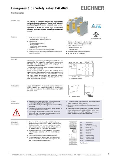
<strong>Emergency</strong> <strong>Stop</strong> <strong>Safety</strong> <strong>Relay</strong> <strong>ESM</strong>-<strong>BA3.</strong>.User Information<strong>Co</strong>rrect UseThe <strong>ESM</strong>-<strong>BA3.</strong>. is a universal emergency stop safety switchingdevice with three safe relay outputs that can quickly and safelystop the moving parts of a machine or system in case of danger.Applications for the <strong>ESM</strong>-<strong>BA3.</strong>. include single or dual-channelemergency stop circuits and guard monitoring on machines andsystems.Features• 3 safe, redundant relay outputs1 auxiliary contact (signaling contact)• <strong>Co</strong>nnection of:- <strong>Emergency</strong> stop buttons- <strong>Safety</strong> switches- Non-contact safety switches- OSSD-Outputs• Single and dual-channel operation possible• Feedback loop for monitoring downstream contactors orexpansion modules• Cyclical monitoring of the output contacts• Indication of the switching state via LED• 2 start behaviors possible:- Monitored manual start- Automatic start• Short circuit and earth fault monitoring• Up to PL e, SILCL 3, category 4(not for plug-in terminals)FunctionThe emergency stop safety switching device <strong>ESM</strong>-<strong>BA3.</strong>. isdesigned for safe isolation of safety circuits according toEN 60204-1 and can be used up to safety category 4, PL eaccording to EN ISO 13849-1.The internal logical system closes the safety contacts whenthe start button is pressed.When the safety switch is opened, the positively drivensafety contacts are opened and safely switch the machineoff. It is ensured that a single fault does not lead to a loss ofthe safety function and that every fault is detected by cyclicalself-monitoring no later than when the system is switchedoff and switched on again.Fig. 1 Block diagram <strong>ESM</strong>-<strong>BA3.</strong>.InstallationAs per EN 60204-1, the device is intended for installation incontrol cabinets with a minimum degree of protection ofIP54. It is mounted on a 35 mm DIN rail according to DINEN 60715 TH35.Fig. 2 Installation / removal<strong>Safety</strong>Precautions• Installation and commissioning of the device must beperformed only by authorized personnel.• Observe the country-specific regulations when installingthe device.• The electrical connection of the device is only allowed tobe made with the device isolated.• The wiring of the device must comply with the instructionsin this user information, otherwise there is a riskthat the safety function will be lost.• It is not allowed to open the device, tamper with the deviceor bypass the safety devices.• All relevant safety regulations and standards are to beobserved.• The overall concept of the control system in which thedevice is incorporated must be validated by the user.• Failure to observe the safety regulations can result indeath, serious injury and serious damage.Electrical<strong>Co</strong>nnection• When the 24 V version is used, a safety transformeraccording to EN 61558-2-6 or a power supply unit withelectrical isolation from the mains must be connected.• External fusing of the safety contacts (6A slow-blow or8A quick-action or 10 A gG) must be provided.• A maximum length of the control lines of 1000 meterswith a line cross section of 0.75 mm 2 must not be exceeded.• The line cross section must not exceed 2.5 mm 2 .• If the device does not function after commissioning, itmust be returned to the manufacturer unopened. Openingthe device will void the warranty.A1: Power supplyA2 : Power supplyS11: DC 24V control voltageS10: <strong>Co</strong>ntrol lineS21: Start control lineS13: <strong>Co</strong>ntrol lineS14: <strong>Co</strong>ntrol lineS12: <strong>Co</strong>ntrol line13-14: <strong>Safety</strong> contact 123-24: <strong>Safety</strong> contact 233-34: <strong>Safety</strong> contact 341-42: Auxiliary contactFig. 3 <strong>Co</strong>nnections<strong>EUCHNER</strong> <strong>GmbH</strong> + <strong>Co</strong>. KG Kohlhammerstraße 16 D-70771 Leinfelden-Echterdingen Tel. +49/711/75 97-0 Fax +49/711/75 33 16 www.euchner.de info@euchner.de1
<strong>Emergency</strong> <strong>Stop</strong> <strong>Safety</strong> <strong>Relay</strong> <strong>ESM</strong>-<strong>BA3.</strong>.User InformationDimensionDrawing22,599114Subject to technical modifications, no responsibility is accepted for the accuracy of this information. © <strong>EUCHNER</strong> <strong>GmbH</strong> + <strong>Co</strong>. KG 090073-03-09/11 (Translation of the Original Operating Instructions)<strong>EUCHNER</strong> <strong>GmbH</strong> + <strong>Co</strong>. KG Kohlhammerstraße 16 D-70771 Leinfelden-Echterdingen Tel. +49/711/75 97-0 Fax +49/711/75 33 16 www.euchner.de info@euchner.de4