Betriebsanleitung Sicherheitsschalter NM..HB - EUCHNER GmbH + ...
Betriebsanleitung Sicherheitsschalter NM..HB - EUCHNER GmbH + ...
Betriebsanleitung Sicherheitsschalter NM..HB - EUCHNER GmbH + ...

You also want an ePaper? Increase the reach of your titles
YUMPU automatically turns print PDFs into web optimized ePapers that Google loves.
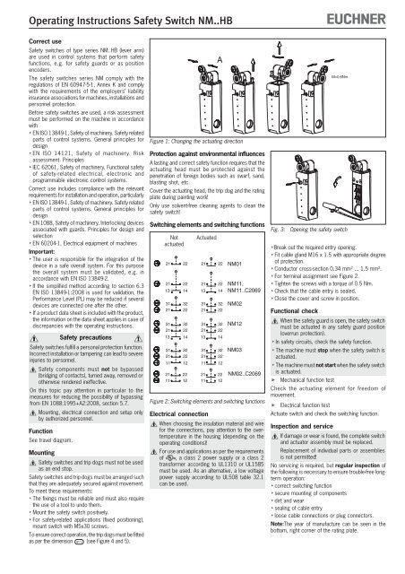
Operating Instructions Safety Switch <strong>NM</strong>..<strong>HB</strong>Correct useSafety switches of type series <strong>NM</strong>..<strong>HB</strong> (lever arm)are used in control systems that perform safetyfunctions, e.g. for safety guards or as positionencoders.The safety switches series <strong>NM</strong> comply with theregulations of EN 60947-5-1, Annex K and complywith the requirements of the employers’ liabilityinsurance associations for machines, installations andpersonnel protection.Before safety switches are used, a risk assessmentmust be performed on the machine in accordancewith EN ISO 13849-1, Safety of machinery. Safety relatedparts of control systems. General principles fordesign EN ISO 14121, Safety of machinery. Riskassessment. Principles IEC 62061, Safety of machinery. Functional safetyof safety-related electrical, electronic andprogrammable electronic control systems.Correct use includes compliance with the relevantrequirements for installation and operation, particularly EN ISO 13849-1, Safety of machinery. Safety relatedparts of control systems. General principles fordesign EN 1088, Safety of machinery. Interlocking devicesassociated with guards. Principles for design andselection EN 60204-1, Electrical equipment of machinesImportant: The user is responsible for the integration of thedevice in a safe overall system. For this purposethe overall system must be validated, e.g. inaccordance with EN ISO 13849-2. If the simplified method according to section 6.3EN ISO 13849-1:2008 is used for validation, thePerformance Level (PL) may be reduced if severaldevices are connected one after the other. If a product data sheet is included with the product,the information on the data sheet applies in case ofdiscrepancies with the operating instructions.Safety precautionsSafety switches fulfill a personal protection function.Incorrect installation or tampering can lead to severeinjuries to personnel.Safety components must not be bypassed(bridging of contacts), turned away, removed orotherwise rendered ineffective.On this topic pay attention in particular to themeasures for reducing the possibility of bypassingfrom EN 1088:1995+A2:2008, section 5.7.Mounting, electrical connection and setup onlyby authorized personnel.FunctionSee travel diagram.MountingSafety switches and trip dogs must not be usedas an end stop.Safety switches and trip dogs must be arranged suchthat they are adequately secured against movement.To meet these requirements: The fixings must be reliable and must also requirethe use of a tool to undo them. Mount the safety switch positively. For safety-related applications (fixed positioning),mount switch with M5x30 screws.To ensure correct operation, the trip dogs must be fittedas per the dimension 41 +1 0 (see Figure 4 and 5).Figure 1: Changing the actuating directionProtection against environmental influencesA lasting and correct safety function requires that theactuating head must be protected against thepenetration of foreign bodies such as swarf, sand,blasting shot, etc.Cover the actuating head, the trip dog and the ratingplate during painting work!Only use solvent-free cleaning agents to clean thesafety switch!Switching elements and switching functionsNotactuated212113312131211331211121112222143222322214322212Actuated212113312131211331211122 2112 11Figure 2: Switching elements and switching functionsElectrical connectionWhen choosing the insulation material and wirefor the connections, pay attention to the overtemperaturein the housing (depending on theoperating conditions)!For use and applications as per the requirementsof , a class 2 power supply or a class 2transformer according to UL1310 or UL1585must be used. As an alternative, a low voltagepower supply according to UL508 table 32.1can be used.A2222143222322214322212<strong>NM</strong>01<strong>NM</strong>11,<strong>NM</strong>11..C2069<strong>NM</strong>02<strong>NM</strong>12<strong>NM</strong>0322 <strong>NM</strong>02..C206912Fig. 3:Opening the safety switchBreak out the required entry opening. Fit cable gland M16 x 1.5 with appropriate degreeof protection. Conductor cross-section 0.34 mm 2 ... 1.5 mm². For terminal assignment see Figure 2. Tighten the screws with a torque of 0.5 Nm. Check that the cable entry is sealed. Close the cover and screw in position.Functional checkM=0,6NmWhen the safety guard is open, the safety switchmust be actuated in any safety guard position(overrun protection). In safety circuits, check the safety function. The machine must stop when the safety switch isactuated. The machine must not start when the safety switchis actuated. Mechanical function testCheck the actuating element for freedom ofmovement. Electrical function testActuate switch and check the switching function.Inspection and serviceIf damage or wear is found, the complete switchand actuator assembly must be replaced.Replacement of individual parts or assembliesis not permitted!No servicing is required, but regular inspection ofthe following is necessary to ensure trouble-free longtermoperation: correct switching function secure mounting of components dirt and wear sealing of cable entry loose cable connections or plug connectors.Note:The year of manufacture can be seen in thebottom, right corner of the rating plate.