Schede Tecniche Opere Provvisionali per la messa in sicurezza ...
Schede Tecniche Opere Provvisionali per la messa in sicurezza ...
Schede Tecniche Opere Provvisionali per la messa in sicurezza ...

You also want an ePaper? Increase the reach of your titles
YUMPU automatically turns print PDFs into web optimized ePapers that Google loves.
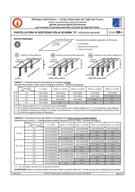
M<strong>in</strong>istero dell’Interno – Corpo Nazionale dei Vigili del FuocoNucleo coord<strong>in</strong>amento o<strong>per</strong>e provvisionali<strong>Schede</strong> <strong>Tecniche</strong> <strong>O<strong>per</strong>e</strong> <strong>Provvisionali</strong><strong>per</strong> <strong>la</strong> <strong>messa</strong> <strong>in</strong> <strong>sicurezza</strong> post-sisma da parte dei Vigili del FuocoPUNTELLATURA DI SOSTEGNO SOLAI SCHEMA “S”: <strong>in</strong>dicazioni generaliSTOP-SB/SSchemi tipologiciLNomenc<strong>la</strong>tura e parametri geometrici di riferimentoS(orditura)L : luce del so<strong>la</strong>ioi : <strong>in</strong>terasse trasversale puntelliH : altezza di <strong>in</strong>terpianoS1 PUNTELLATURA SINGOLA S2 PUNTELLATURA DOPPIA PARALLELA S3 PUNTELLATURA TRIPLA PARALLELALLLtrave ditrave ditrave disostegnosostegnosostegnoHHHiiiipuntelloipuntelloipuntelloL/3 L/3 L/3L/4 L/4 L/4 L/4Tabel<strong>la</strong> 1 - Dimensionamento del sistema di sostegno <strong>in</strong> legnoSezione del puntello e del<strong>la</strong> trave di sostegno (cmxcm) – [schema tipologico]H f<strong>in</strong>o a 4 mi (m)L (m)L ≤ 3.0m 3.0m < L ≤ 4.0m 4.0m < L ≤ 5.0m 5.0m < L ≤ 6.0m 6.0m < L ≤ 7.0m1.0 13x13-[S1] 13x13-[S1] 13x13-[S2] 13x13-[S3] 13x13-[S3]1.5 13x13-[S1] 13x13-[S2] 13x13-[S3] 15x15-[S3] n.c.2.0 15x15-[S2] 15x15-[S2] 15x15-[S3] n.c. n.c.2.5 15x15-[S3] n.c. n.c. n.c. n.c.H 4 - 6 mPer altezze su<strong>per</strong>iori a 4 m lo schema S1 non è utilizzabile.È possibile fare riferimento agli schemi S2 e S3 di sezione pari a quel<strong>la</strong> <strong>in</strong>dicata <strong>per</strong> H < 4m <strong>in</strong>troducendo <strong>per</strong>ò elementirompitratta <strong>in</strong> entrambe le direzioni (n.2 tavole 2.5x12 fissate con n.3 chiodi l=80 mm a metà dell’altezza del puntello) al f<strong>in</strong>edi ridurre <strong>la</strong> lunghezza libera di <strong>in</strong>flessione.Tabel<strong>la</strong> 2 - Dimensionamento del sistema di sostegno con trave <strong>in</strong> legno e puntelli metalliciSezione trave (cmxcm) – C<strong>la</strong>ssificazione puntello (secondo UNI EN 1065) - [schema tipologico]i (m)L (m)L ≤ 3.0m 3.0m < L ≤ 4.0m 4.0m < L ≤ 5.0m 5.0m < L ≤ 6.0m 6.0m < L ≤ 7.0m1.0 13x13-C30-[S1] 13x13-C30-[S2] 13x13-E30-[S2] 13x13-E30-[S3] 13x13-E30-[S3]H< 3 mH= 3-4 mH= 4-5 m1.5 13x13-E30-[S1] 13x13-E30-[S2] 13x13-E30-[S3] n.c. n.c.2.0 15x15-E30-[S2] 15x15-C30-[S3] n.c. n.c. n.c.2.5 15x15-E30-[S3] n.c. n.c. n.c. n.c.1.0 13x13-D40-[S1] 13x13-D40-[S2] 13x13-E40-[S2] 13x13-E40-[S3] 13x13-E40-[S3]1.5 13x13-E40-[S1] 13x13-E40-[S2] 13x13-E40-[S3] n.c. n.c.2.0 15x15-E40-[S2] 15x15-E40-[S3] n.c. n.c. n.c.2.5 15x15-E40-[S3] n.c. n.c. n.c. n.c.1.0 13x13-D50-[S1] 13x13-D50-[S2] 13x13-E50-[S2] 13x13-E50-[S3] 13x13-E50-[S3]1.5 13x13-E50-[S1] 13x13-E50-[S2] 13x13-E50-[S3] n.c. n.c.2.0 15x15-E50-[S2] 15x15-E50-[S3] n.c. n.c. n.c.2.5 15x15-E50-[S3] n.c. n.c. n.c. n.c.n.c. - non contemp<strong>la</strong>to: necessita di una progettazione specificaAVVERTENZA: fissare il puntello metallico al<strong>la</strong> trave di legno su<strong>per</strong>iore utilizzando 1 chiodo <strong>per</strong> ogni foro predisposto sul<strong>la</strong> basettaAprile 2010© CNVVF- Riproduzione consentita <strong>per</strong> solo uso <strong>in</strong>terno del CNVVFSB 2/10