INVERTER - Catellani Tecno Forniture Elettriche srl
INVERTER - Catellani Tecno Forniture Elettriche srl
INVERTER - Catellani Tecno Forniture Elettriche srl

Create successful ePaper yourself
Turn your PDF publications into a flip-book with our unique Google optimized e-Paper software.
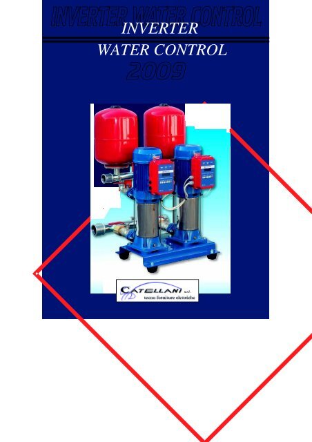
<strong>INVERTER</strong><br />
WATER CONTROL
2<br />
“La Ditta ELECTROIL S.r.l.” opera nel settore degli azionamenti<br />
elettrici per l’industria, l’oleodinamica e per il settore civile<br />
pompe acqua.<br />
Da alcuni anni ELECTROIL si è fatta conoscere per l’elevato<br />
contenuto tecnologico dei suoi prodotti, diventando leader per<br />
gli azionamenti elettrici lineari e rotativi per l’oleodinamica ed<br />
ha sviluppato una gamma di azionamenti inverter per motori<br />
industriali e per pompe acqua e gruppi di pressurizzazione.<br />
Gli ingegneri di ELECTROIL uniscono l’esperienza trentennale<br />
nel settore motori e azionamenti elettrici all’innovazione<br />
continua data dall’ausilio di moderni sistemi di calcolo<br />
numerico per l’analisi elettromagnetica dei sistemi e strumenti<br />
di modellizzazione meccanica 3D ed elettronica.<br />
Tutti i prodotti di ELECTROIL vengono curati dal progetto<br />
alla produzione fi no alla verifi ca di effi cienza e durata<br />
sull’applicazione specifi ca. Questo permette estrema<br />
prontezza di risposta anche per lo studio di applicazioni<br />
speciali personalizzate per il cliente.<br />
Note Tecniche di Prodotto<br />
I dati e le caratteristiche tecniche riportate nel presente Listino Prezzi non sono impegnativi.<br />
ELECTROIL S.r.l. si riserva il diritto di apportare qualsiasi modifi ca senza alcun preavviso. Di<br />
conseguenza pesi, misure, prestazioni e quanto altro indicato non sono vincolanti ma solo<br />
indicativi. In ogni caso, per qualsiasi dettaglio tecnico richiedere direttamente alla ELECTROIL<br />
S.r.l. la scheda tecnica aggiornata del prodotto.<br />
Foro Competente<br />
Per eventuali controversie, il Foro competente sarà quello di Reggio Emilia anche se il<br />
pagamento é avvenuto a mezzo tratta.<br />
ELECTROIL company work in the electromagnetic and<br />
electronic design and production of devices for industry,<br />
hydraulic and the water pumps sector.<br />
From years, ELECTROIL has made known for the high<br />
technological content of its products, becoming leader for<br />
Linear and Rotating Electric Drives<br />
for hydraulics and developed a range of Inverter drives for<br />
industrial motors, water pumps and pressurisation systems.<br />
ELECTROIL engineers join the Thirty years experience<br />
in motors and Electrical drives to the continues innovation<br />
on using of modern Electromagnetic numerical analysis<br />
computing systems, 3D mechanical modelling and electronics<br />
systems.<br />
All products are controlled by ELECTROIL from the project<br />
and production to effi ciency and durability verify on working<br />
ambient. This allows very rapid response specially for the study<br />
of custom applications for the client.<br />
RIVENDITORE AUTORIZZATO<br />
Technical Characteristics<br />
The technical data and characteristics stated in this Price List are not binding. ELECTROIL S.r.l.<br />
reserves the right to make modifi cations without notice. Therefore weights, dimensions,<br />
performances and any other stated issues are indicative only and not binding.<br />
Revisione 01 - 11/2008<br />
Anyway for any technical details you must require an up-to-date product technical card.<br />
Competent Court<br />
In case of any dispute the competent Court will be one of Reggio Emilia even if the payment<br />
is by bill of exchange.
100%<br />
IL RISPARMIO ENERGETICO SULLE ELETTROPOMPE DATO DALL’<strong>INVERTER</strong><br />
ENERGY SAVING ON WATER PUMPS USING <strong>INVERTER</strong><br />
Effi ciency<br />
Speed-fl ow<br />
50%<br />
Fig. 1<br />
100%<br />
Tutti i motori in corrente alternata sono progettati per soddisfare il carico<br />
massimo richiesto in un impianto o in un processo; nella maggior parte<br />
dei casi, questi motori sono connessi direttamente all’alimentazione e<br />
ruotano alla velocità nominale (50 Hz) anche quando non è necessario.<br />
Questo avviene soprattutto in applicazioni di pompe centrifughe e<br />
ventilatori, dove la portata o la pressione sono regolate tramite valvole di<br />
strozzatura o serrande; un tipo di regolazione dissipativa con variazione<br />
delle grandezze d’impianto attraverso l’introduzione di perdite di carico.<br />
Immaginate di guidare un’automobile tenendo il pedale dell’acceleratore<br />
schiacciato al massimo e regolare la velocità del veicolo agendo sul<br />
pedale del freno. Ovviamente ciò<br />
comporterebbe uno spreco energetico<br />
non tollerabile. Con una regolazione a<br />
velocità variabile, invece, si ottengono<br />
sensibili risparmi energetici e quindi<br />
economici, ottimizzando anche il<br />
controllo di quelle che sono le grandezze<br />
d’impianto. Questo perché nelle macchine fl uidodinamiche (pompe centrifughe<br />
e ventilatori) la relazione tra potenza assorbita e velocità è di tipo cubico;<br />
quindi pochi Hz in meno signifi cano molti meno Kw consumati (vedi fi g. 1 ).<br />
L’utilizzo di un convertitore di frequenza per il controllo di un motore, consente<br />
un risparmio energetico anche in applicazioni a coppia costante (vedi fi g. 2).<br />
100% Effi ciency<br />
All AC motors are designed to meet the maximum load required in a plant<br />
or process, in most cases, these motors are connected directly to the voltage<br />
50%<br />
Speed-fl ow<br />
supply and rotate at the rated speed (50 Hz) even when not necessary . This<br />
Fig. 2<br />
happens especially in applications of centrifugal pumps and fans, where the<br />
fl ow or pressure are regulated through valves or dampers bottleneck, a dissipative type of adjustment with<br />
variation of plant characteristics by introducing drop.<br />
Imagine having to drive a car with the accelerator pedal to the maximum and adjusting the speed of the<br />
vehicle pushing on the brake pedal. Obviously this would require a waste energy not tolerable. With a<br />
variable speed adjustment, however, are obtained sensitive energy savings, optimizing the functions of the<br />
plant. This is because the fl uid mechanical machinery (centrifugal pumps and fans) the relationship between<br />
power consumption and speed is a cubic diagram, so few Hz less mean less Kw consumed (see fi g. 1). Using<br />
a frequency converter for controlling an engine, saves energy in constant torque applications (see fi g. 2).<br />
Esempio di risparmio energetico / Energy saving Example:<br />
Applicazione / Application<br />
Potenza nominale / Nominal power<br />
Tempo di funzionamento in un anno / Functioning time for year<br />
Costo medio energia elettrica / Medium price for electrical energy<br />
Costo medio di installazione (inverter + montaggio sulla pompa)<br />
Medium installing cost (inverter + installing)<br />
Velocità media della pompa in % rispetto alla velocità nominale<br />
Medium velocità of the pump on respect the nominal velocity<br />
Risparmio calcolato / Saving calculation:<br />
Costo dell’energia consumata in un anno con regolazione dell’elettropompa tramite Inverter<br />
Energy cost in a year with Inverter pump regulation<br />
Costo dell’energia consumata in un anno con regolazione dell’elettropompa tramite dispositivi meccanici<br />
Energy cost with mechanical pump regulation<br />
Risparmio economico annuo con Inverter / Annual economic savings inverter<br />
Tempo di ammortamento dell’investimento iniziale / Depreciation time of the initial cost<br />
Pompa / Water pump<br />
2.2 kw (3HP)<br />
8760 h (continuativo)<br />
(continuus)<br />
0.2 € / kWh<br />
400 €<br />
70%<br />
1322 €<br />
3468 €<br />
2146 €<br />
55 giorni<br />
100%
4<br />
VANTAGGI NEL CONTROLLO<br />
DI PRESSIONE CON <strong>INVERTER</strong><br />
Quando una abitazione o un condominio a più<br />
appartamenti sono alimentati da una o più<br />
elettropompe con inverter i vantaggi sono<br />
molteplici:<br />
• Mantenimento di una pressione costante<br />
impostata anche con bassissima richiesta d’acqua<br />
o nelle ore di massima richiesta d’acqua;<br />
• Possibilità di impiego di un accumulatore molto<br />
piccolo;<br />
• Eliminazione dei picchi di pressione detti “colpo<br />
d’ariete” che possono danneggiare la pompa e<br />
l’impianto;<br />
• Protezione termica dell’elettropompa integrata<br />
nell’Inverter;<br />
• Protezione contro il picco di corrente;<br />
• Protezione della pompa contro il funzionamento<br />
a secco;<br />
• Protezione della pompa contro la marcia a<br />
mandata chiusa;<br />
• Possibilità di funzionamento in parallelo di due<br />
o più pompe controllate da Inverter comunicanti<br />
(principio di funzionamento come in fi gura 3).<br />
<strong>INVERTER</strong> WATER CONTROL<br />
ADVANTAGES IN CONTROL PRESSURE<br />
WITH <strong>INVERTER</strong><br />
When a house or a condominium composed<br />
by more apartments are powered by one or<br />
more electropumps with inverter the benefi ts<br />
are manifold:<br />
• Maintaining a constant pressure set with low<br />
demand of water or in the hours of peak<br />
demand of water;<br />
• May use a very small accumulator;<br />
• Eliminate peak pressure that can damage the<br />
pump and plant;<br />
• Integrated thermal protection of the inverter;<br />
• Pick current protection<br />
• Pump protection against dry running;<br />
• Pump protection against the closed running;<br />
• Serial BUS connection of two or more<br />
pumps controlled by communicating Inverters<br />
(principle of work described in Fig. 3).<br />
SISTEMA TRADIZIONALE<br />
STANDARD SYSTEM<br />
Pump 1<br />
MASTER-SLAVE COMMUNICATION SYSTEM FOR GROUP OF PUMPS WITH <strong>INVERTER</strong>S<br />
• Master-Slave functioning with RS485 bus;<br />
• Up to 30 Inverters for group;<br />
Pump 2<br />
Fig. 3<br />
SISTEMA CON <strong>INVERTER</strong><br />
<strong>INVERTER</strong> SYSTEM<br />
Pump 1<br />
Pump 2<br />
FUNZIONAMENTO DI GRUPPI DI ELETTROPOMPE CON <strong>INVERTER</strong> COMUNICANTI<br />
• Funzionamento tipo Master-Slave tramite bus RS485;<br />
• Fino a 30 inverters comunicanti;<br />
• Semplice confi gurazione degli inverters (è suffi ciente inserire un codice 0 per il<br />
Master e un codice da 1 a 30 per i restanti Slaves);<br />
• Perfetta sincronizzazione tra gli Inverters;<br />
• Regolazione molto fi ne e graduale della pressione;<br />
• Assenza di picchi di pressione (colpi d’ariete) per l’assenza del motore alimentato<br />
direttamente da rete;<br />
• Notevole risparmio su cablaggi e installazione rispetto ai normali gruppi pompe con<br />
quadro elettrico standard;<br />
• Simple confi guration between inverters (only need to defi ne a code 0 for the Master and a code 1..30 for the others Slaves);<br />
• Perfect synchronization between inverters;<br />
• Precision on the pressure regulation;<br />
• No pressare pick because there isn’t a direct motor and the velocity incising is soft;<br />
• Substantial savings on wiring and installation compared to normal groups of pumps with standard control cabinet;<br />
FLUSSO / FLOW
Regolazione della pressione<br />
mediante potenziometro<br />
IMP 1100 WP-O<br />
Pressure regulation with potentiometer<br />
Tensione alimentazione inverter monofase IMP 1100WP<br />
Single-phase voltage supply IMP 1100 WP<br />
Corrente massima all’uscita<br />
Maximum current on the three output phases<br />
Potenza massima Motore / Maximum motor Power<br />
IP / IP<br />
Flangia standard / Standard Fixing<br />
Confi gurazioni di montaggio / Mounting confi guration<br />
IMP 1100 WP<br />
Inverter monofase 1.1 Kw per elettropompa<br />
S ingle -phase 1.1 Kw inver te fo r pumps<br />
IMP 1100 WP-V<br />
Molto semplice da installare e da usare<br />
Very simple to install and use<br />
IMP 1100 WP - SPECIFICHE / GENERAL DATA<br />
100 ÷ 244 Vrms AC / 50-60 Hz<br />
6 Arms<br />
CODICI DI ORDINAZIONE - ORDERING CODES<br />
1.1 kW (1.5 CV)<br />
5.5<br />
MEC 56 - 71 STD<br />
MEC 56 - 71 CAME version<br />
MEC 80 - 112<br />
verticale / orizzontale<br />
vertical / orizontal<br />
EF. 822.xx.yy.01 IMP 1100WP: Inverter monofase bordo pompa per regolazione di pressione con potenziometro<br />
XX - TIPO DI MONTAGGIO <strong>INVERTER</strong><br />
01<br />
02<br />
YY - TIPO DI ATTACCO MORSETTIERA MOTORE<br />
01<br />
02<br />
03<br />
Per montaggio verticale<br />
Montaggio Orizzontale (comandi ruotati di 90°)<br />
MEC 56-71 standard<br />
MEC 56-71 tipo CAME / Veneta Press<br />
MEC 80-112 standard<br />
5
6<br />
Possibilità di funzionamento in gruppo<br />
mediante collegamento seriale<br />
Master-slave communication system for<br />
group of pumps<br />
DIMENSIONI E QUOTE DI FISSAGGIO<br />
DIMENSIONS AND FIXING<br />
EMC<br />
APPROVED<br />
IMP - ITP 2200 WP<br />
Disponibile nelle versioni<br />
monofase e trifase<br />
Single phase and three phases<br />
versions available
IMP - ITP 2200 WP<br />
Inverter monofase / trifase 2.2 Kw per elettropompa<br />
Single phase and three phase 2.2 Kw Inverter for pumps<br />
IMP2200 WP - V<br />
ITP2200 WP - V<br />
Tensione alimentazione inverter monofase IMP 2200WP<br />
Single-phase version voltage supply IMP 2200 WP<br />
Tensione alimentazione inverter trifase ITP 2200WP<br />
Three-phase version voltage supply ITP 2200WP<br />
IMP2200 WP - O<br />
ITP2200 WP - O<br />
IMP - ITP 2200 WP - SPECIFICHE / GENERAL DATA<br />
Corrente massima all’uscita /Maximum current on the three output phases<br />
Potenza massima Motore / Maximum motor Power<br />
IP / IP<br />
Flangia standard / Standard Fixing<br />
Confi gurazioni di montaggio / Mounting confi guration<br />
Comunicazione seriale / Serial Bus<br />
EF. 814.xx.yy.01<br />
EF. 813.xx.yy.01<br />
XX - TIPO DI MONTAGGIO <strong>INVERTER</strong><br />
01<br />
CODICI DI ORDINAZIONE - ORDERING CODES<br />
IMP 2200WP: Inverter monofase bordo pompa<br />
ITP 2200WP: Inverter trifase bordo pompa<br />
Per montaggio verticale<br />
02 Montaggio Orizzontale (display e comandi ruotati di 90°)<br />
YY - TIPO DI ATTACCO MORSETTIERA MOTORE<br />
01<br />
02<br />
03<br />
MEC 56-71 standard<br />
MEC 56-71 tipo CAME / Veneta Press<br />
MEC 80-112 standard<br />
100 - 244 VRMS AC - 50÷60 Hz<br />
200 - 440 VRMS AC - 50÷60 Hz<br />
10 ARMS (Monofase / Single phase)<br />
6 ARMS (Trifase / Three phases)<br />
2200W (3 HP)<br />
55<br />
MEC 56 - 71 STD<br />
MEC 56 - 71 CAME version<br />
MEC 80 - 112<br />
Verticale / Orizzontale<br />
Vertical / Orizontal<br />
RS 485 Master-Slave<br />
7
8<br />
ITP 5500 WP<br />
Inverter trifase 5.5 Kw per elettropompa / Three phase 5.5 Kw Inverter for pumps<br />
ITP5500 WP - V<br />
ITP5500 WP - O
Controllo vettoriale / Vectorial control<br />
Elevata effi cienza / High effi ciency<br />
ABBINAMENTO AL SENSORE<br />
DI PRESSIONE PS1 – 10 BAR<br />
MY USE WITH PRESSURE<br />
SENSOR PS1 - 10 BAR<br />
Il sensore Electroil PS1 nella<br />
versione con portata 0 - 10BAR è<br />
specifi co per pompe acqua ed è<br />
disponibile nelle versioni<br />
con fi lettatura:<br />
1/8” GAS - 1/4” GAS - 3/8” GAS<br />
Pressure sensor Electroil PS1<br />
(version 0 – 10 BAR) is specifi c<br />
for use with water<br />
pumps-available fi xings:<br />
1/8” GAS - 1/4” GAS - 3/8” GAS<br />
ITP 5500 WP - SPECIFICHE / GENERAL DATA<br />
Tensione alimentazione inverter trifase ITP 5500 WP<br />
Three phases voltage supply ITP 5500 WP<br />
200-440 Vrms AC, 50÷60 Hz<br />
Corrente massima all’uscita / Maximum current on the three output phases 13 ARMS<br />
Potenza massima motore / Maximum motor power<br />
IP / IP<br />
Flangia standard / Standard Fixing<br />
Confi gurazioni di montaggio / Mounting confi guration<br />
CODICI DI ORDINAZIONE - ORDERING CODES<br />
5.5 kW (7,5 CV)<br />
55<br />
MEC 80÷112<br />
MEC 132<br />
verticale / vertical<br />
orizzontale / orizontal<br />
EF. 820.xx.yy.01 ITP 5500WP: Inverter trifase per montaggio bordo pompa<br />
XX - TIPO DI MONTAGGIO <strong>INVERTER</strong><br />
01<br />
Per montaggio verticale<br />
02 Montaggio orizzontale (display e comandi ruotati di 90°)<br />
YY - TIPO DI ATTACCO MORSETTIERA MOTORE<br />
03<br />
04<br />
MEC 80-112 STANDARD<br />
MEC 132 STANDARD<br />
9
10<br />
IMP 2200 WPP<br />
Inverter monofase 2.2 Kw montaggio a parete per controllo elettropompa<br />
Single phase 2.2 Kw inverter wall mounting for pump control<br />
IMP 2200 WPP<br />
Particolarmente indicato<br />
per pompe sommerse e<br />
sommergibili.<br />
Special for submersible pumps.<br />
Possibilità di funzionamento in<br />
gruppo<br />
mediante seriale<br />
Master-slave communication<br />
system for<br />
group of pumps<br />
IMP 2200 WPP - SPECIFICHE / GENERAL DATA<br />
Tensione alimentazione inverter monofase IMP 2200WP<br />
Single-phase voltage supply IMP 2200 WP<br />
100 - 244 Vrms AC<br />
Corrente massima all’uscita<br />
Maximum current on the three output phases<br />
10 A rms<br />
Potenza massima Motore / Maximum motor Power<br />
2200 W (3 CV)<br />
IP / IP<br />
55<br />
Comunicazione seriale / Serial bus<br />
Confi gurazioni di montaggio / Mounting confi guration<br />
Dimensioni / Dimensions<br />
EF. 81505001<br />
CODICI DI ORDINAZIONE - ORDERING CODE<br />
Inverter monofase 2.2 kW da parete<br />
Single phase 2.2 kW inverter wall mounting<br />
RS 485 Master-slave<br />
Verticale da parete<br />
Vertical wall mounting<br />
160 x 120 x 300 mm
ITP 3000 WPP<br />
Inverter trifase 3 Kw montaggio a parete per controllo elettropompa<br />
Three phases 3 Kw inverter wall mounting for pump control<br />
ITP 3000 WPP<br />
Particolarmente indicato<br />
per pompe sommerse e<br />
sommergibili.<br />
Special for submersible pumps.<br />
Possibilità di funzionamento in<br />
gruppo mediante seriale.<br />
Master-slave communication<br />
system for group of pumps.<br />
Completo di fi ltro EMC in<br />
contenitore di alluminio.<br />
Provided with EMC fi lter in<br />
aluminium box.<br />
Semplice installazione, completamente cablato / Simple installation, fully wired<br />
Tensione alimentazione inverter trifase ITP 3000 WPP<br />
Three phases version voltage supply ITP 3000 WPP<br />
Corrente massima all’uscita<br />
Maximum current on the three output phases<br />
Potenza massima motore / Maximum motor power<br />
IP / IP<br />
Comunicazione seriale / Serial bus<br />
Confi gurazioni di montaggio / Mounting confi guration<br />
Dimensioni / Dimensions<br />
EF. 816 05 001<br />
ITP 3000 WPP - SPECIFICHE / GENERAL DATA<br />
200 - 440 VRMS AC<br />
8 ARMS<br />
3.0 kW (4 Hp)<br />
55<br />
RS 485<br />
CODICI DI ORDINAZIONE - ORDERING CODE<br />
Inverter trifase 3.0 Kw da parete<br />
Three phase 3.0 Kw inverter wall mounting<br />
Verticale a parete<br />
Vertical wall mounting<br />
160 x 120 x 300 mm<br />
11
12<br />
PRODUCT SPECIFICATIONS<br />
IPC02 /IPC03 govern a system that is made up by<br />
two or more centrifugal pumps, these are moved by<br />
asynchronous motor; one of these pumps is controlled<br />
on angular velocity by a frequency converter, while<br />
the other ones are supplied by voltage supply with<br />
controlled contactors. This system has to keep the<br />
pressure steady, independently from the fl ow.<br />
IPC2-01 / IPC3-01<br />
Controllo ad Inverter per gruppi pompe<br />
Inverter control system for water pumps group<br />
CARATTERISTICHE DEL PRODOTTO<br />
Il quadro IPC2 / IPC3 governa un sistema composto<br />
da due o tre pompe centrifughe, azionate da<br />
motore asincrono; una di queste è controllata in<br />
velocità da un convertitore di frequenza,<br />
mentre le altre sono alimentate tramite<br />
contattori dalla tensione di rete.<br />
Il sistema mantiene costante la<br />
pressione, indipendentemente<br />
dal fl usso di fl uido. Il sistema è<br />
specifico per la distribuzione<br />
dell’acqua per uso civile e<br />
industriale per medie e grandi<br />
utenze. La pressione a valle<br />
è monitorata da un sensore di<br />
pressione, che dà un’uscita<br />
analogica.<br />
Per mantenere costante la<br />
pressione, la logica interviene<br />
sulla frequenza di alimentazione della<br />
pompa sotto Inverter e sull’accensione/<br />
spegnimento<br />
delle pompe dirette.<br />
It is specifi c for water distribution for civil use. The<br />
output pressure is monitored by a pressure transducer,<br />
analog output. The control logic changes the supply<br />
frequency. Of the inverter pump and the ON/OFF<br />
pumps start and stops.<br />
Russian Language<br />
NEW<br />
Version
A.C.<br />
(3x400 V)<br />
CONVERTITORE DI FREQUENZA - FREQUENCY CONVERTER<br />
Rec<br />
Pressione massima - Max pressure<br />
D.C.<br />
Temperatura di lavoro - Working temperature<br />
Max umidità relativa - Max relative humidity<br />
Indice di protezione - Protection Index<br />
Temperatura del fl uido - Liquid temperature<br />
Int<br />
Cont<br />
Transm<br />
D.C.<br />
Inv<br />
A.C.<br />
D.C.<br />
Rec<br />
IPC2 - IPC3 CONDIZIONI DI LAVORO - WORKING CONDITIONS<br />
Potenza nominale massima del motore comandato dall’inverter Max<br />
nominal power of the Motor driven by the inverter<br />
Tensione nominale dell’inverter - Nominal Voltage supply of the inverter V<br />
Tensione di uscita del convertitore di frequenza<br />
Output voltage of the frequency converter<br />
Frequenza di uscita del convertitore di frequenza<br />
Output frequency of the frequency converter<br />
Corrente nominale in ingresso del convertitore di frequenza<br />
Input nominal current of the frequency converter<br />
Temperatura di stoccaggio - Stocking temperature<br />
Lingue - Languages<br />
CODICI DI ORDINAZIONE - ORDERING CODE<br />
EF. 810.11.001 For 2 PUMPS 1 ÷ 5,5 KW (IPC2-01)<br />
EF. 810.11.002 For 3 PUMPS 1 ÷ 5,5 KW (IPC3-01)<br />
bar<br />
°C<br />
°C<br />
°C<br />
kW<br />
V<br />
Hz<br />
A<br />
°C<br />
Int<br />
Inv<br />
M<br />
A.C.<br />
(3x400 V)<br />
M<br />
alternative current<br />
direct current<br />
rectifi er - raddrizzatore<br />
IGBT intermediate driver<br />
circuit<br />
IGBT bridge three-phase<br />
inverter<br />
motor<br />
Cont control logic by<br />
micro-processor<br />
Transm. Transmission line to ext.<br />
Pressure sensor limit<br />
From 0 to 40<br />
50% at 40<br />
IP54<br />
From 1 to 40<br />
5.5<br />
400 V - 50Hz - three phase<br />
0-400<br />
1-60<br />
15<br />
From –20 to 60<br />
(short period - periodi brevi)<br />
Italian / English / Russian<br />
13
14<br />
Se la pressione aumenta, la logica diminuisce la<br />
frequenza fi no ad un valore minimo impostato; al di<br />
sotto di questo valore viene immediatamente spenta<br />
una delle pompe on/off;<br />
E’ possibile impostare un valore di massima pressione<br />
impianto. La pompa controllata dall’inverter,<br />
può lavorare fi no ad un massimo di frequenza<br />
(impostabile) oltre a quella nominale del motore.<br />
Allarme funzionamento a secco: quando il sistema è<br />
a secco, tutte le pompe vengono spente;<br />
Allarme funzionamento a mandata chiusa.<br />
Giornalmente la logica cambia l’ordine di accensione<br />
delle pompe, in modo da sfruttarle allo stesso modo<br />
sia in funzionamento ON/OFF che sotto Inverter;<br />
La protezione della pompa sotto inverter è garantita<br />
da una limitazione di corrente (impostabile); le<br />
pompe on/off sono protette da un dispositivo<br />
magneto-termico;<br />
Controllo preciso della pressione<br />
Elimina il colpo d’ariete<br />
Risparmio energetico<br />
FLUSSO - FLOW<br />
SISTEMA TRADIZIONALE<br />
STANDARD SYSTEM<br />
Pump 1<br />
IPC 2-01 / IPC 3-01<br />
PRINCIPIO DI FUNZIONAMENTO<br />
Pump 2<br />
FUNCTIONING<br />
While the pressure increases, the control logic<br />
decreases the frequency to a minimum set value;<br />
under this value the control logic switches off<br />
immediately one of the on/off pumps;<br />
It is possible to set a maximum value of the plant<br />
pressure; The pump controlled by the inverter, can<br />
work until a maximum frequency (that has to be set)<br />
upper than motor nominal frequency.<br />
Dry working alarm when the system is dry, all the<br />
pumps switch off;<br />
Pump protection against closed running;<br />
Everyday, the control logic changes the start order<br />
of the pumps in order to preserve their life; The<br />
protection of the inverters pump is made by a current<br />
limitation; for the other pumps there is a magneto-<br />
thermal security device;<br />
Fine pressure control<br />
Eliminate peak pressure that can damage<br />
the pump and plant<br />
Energy saving<br />
SISTEMA CON <strong>INVERTER</strong><br />
<strong>INVERTER</strong> SYSTEM<br />
Pump 1<br />
Pump 2
Versione - Version<br />
PS1<br />
Alimentazione - Power supply<br />
Corrente assorbita - Supply current<br />
Absolute<br />
7 Vdc – 30 Vdc<br />
10 mA<br />
SENSORE DI PRESSIONE<br />
PIEZO-RESISTIVO PROFESSIONALE<br />
PROFESSIONAL<br />
PIEZO-RESISTIVE PRESSURE SENSOR<br />
PS1 é un nuovo professionale sensore di<br />
pressione piezo-resistivo. PS1 é controllato da<br />
un microprocessore in grado di rilevare da 10<br />
mBar fi no a 10 Bar con estrema precisione e<br />
compensando gli effetti della temperatura.<br />
Uscita analogica in tensione.<br />
PS1 is the new professional piezo-resistive<br />
pressure sensor. It is fi tted with a microcontroller<br />
capable of detecting from 10 mbar to 10bar<br />
with extreme accuracy, compensating the<br />
effect of temperature. It has an analog voltage<br />
output signal.<br />
Il sensore è fornito completo di cavo tripolare (2 metri)<br />
The sensor is supplied with a 3 poles cable (2 meters):<br />
CONNESSIONI / ELECTRICAL CONNECTIONS:<br />
• Filo marrone - Brown wire + Vdc<br />
• Filo verde - Green wire S - Sensor signal<br />
• Filo bianco - White wire - Vdc<br />
G 1/4”<br />
Uscita pressione - Pressure output Low impedance - Digital or analog output: 0 – 4,5 Volt<br />
Temperatura lavoro - Working temperature Up to 100°C<br />
Campo pressione - Pressure range<br />
Sovraccarico pressione - Burst pressure<br />
Mezzo - Pressure medium<br />
Risoluzione - Resolution (1 LSB)<br />
Offset shift with temperature<br />
Span shift with temperature<br />
Isteresi pressione - Pressure hysteresis<br />
Ripetibilità - Repeatability<br />
Tempi di risposta - Response time<br />
Linearità - Linearity<br />
Materiali - Materials<br />
Peso - Weight<br />
Altre caratteristiche - Main features<br />
G 3/8”<br />
0-25 kPa (0.25 bar); 0-50 kPa (0.5 bar); 0-100 kPa (1 bar); 0-200 kPa<br />
(2 bar) 0-1000 kPa (10 bar); -100..0 kPa (- 1 bar, VACUUM TYPE)<br />
2000 kPa (20 bar)<br />
G 1/8”<br />
Aria, acqua, vapore, fl uidi non aggressivi. / Air, water, steam. Every non aggressive fl uids.<br />
Typical 10 mV<br />
Typical -5 mV/deg<br />
Min -0.03 / max 0.03 % Span/deg<br />
Min -0.05 / max 0.05 % Span<br />
Min -0.05 / max 0.05 % Span<br />
< 100 ms<br />
Min -0.25 / max 0.25 % Span<br />
Corpo in ottone / Brass body<br />
Struttura interna in resina epossidica classe H / Internal structure epoxy resin class H<br />
Diaframma sensore: piezoresistivo con base ceramica / Diaphragm: silicon piezo-resistive chip on ceramic base<br />
80 g<br />
Alta precisione, alta linearità, attacchi a richiesta con fi lettatura 1/8” gas e 3/8” gas.<br />
Offset e guadagno calibrati. Compensazione di temperatura, corpo igroscopico in ottone.<br />
High precision, high linearity, threaded inlet 1/8” Gas, 3/8” Gas,<br />
calibrated offset, calibrated gain, temperature compensation, brass hygroscopic housing.<br />
15
SPECIALISTI NEI SISTEMI<br />
DI CONTROLLO POMPE<br />
SPECIALISTS IN<br />
CONTROL PUMPS SYSTEMS<br />
RIVENDITORE AUTORIZZATO<br />
CATELLANI <strong>Tecno</strong> <strong>Forniture</strong> <strong>Elettriche</strong> <strong>srl</strong><br />
Viale Ramazzini 35/b – 42100 Reggio Emilia<br />
Tel. 0522 517299 6 linee r.a. – Fax. 0522 921291<br />
e-mail: giulia@catellani.net – service@catellani.net<br />
web site: www.catellani.net