You also want an ePaper? Increase the reach of your titles
YUMPU automatically turns print PDFs into web optimized ePapers that Google loves.
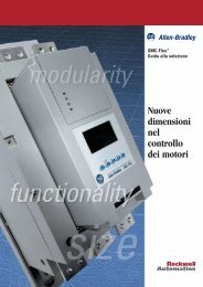
Technical Data<br />
PowerFlex® <strong>70</strong><br />
<strong>AC</strong> <strong>Drives</strong>
Product Overview<br />
PowerFlex® <strong>70</strong> <strong>AC</strong> Drive Technical Data<br />
Optimized Simplicity<br />
PowerFlex® <strong>70</strong> drives are designed to worldwide standards and ratings, allowing outof-the-box<br />
performance around the globe. Available ratings include: 0.5 to 10 HP<br />
output at 240V <strong>AC</strong> input, 0.5 to 20 HP output at 480V <strong>AC</strong> input, 0.5 to 20 HP output at<br />
600V <strong>AC</strong> input.<br />
The PowerFlex <strong>70</strong> drive can be used with a cost effective LED Human Interface<br />
Module or a fuller featured LCD version, which provides multilingual test for startup,<br />
metering, programming and troubleshooting.<br />
The PowerFlex <strong>70</strong> can be programmed for either Volts per Hertz or Sensorless Vector<br />
Control to cover a wide range of applications from fans to extruders.<br />
Optional internal communication modules provide fast and efficient control and/or<br />
data exchange with host controllers over popular interfaces. These interfaces include:<br />
DeviceNet, EtherNet, ControlNet, Remote I/O, Serial Communications and other<br />
open control and communication networks. PC tools such as DriveExplorer and<br />
DriveTools 2000 assist with programming, monitoring, and troubleshooting the<br />
PowerFlex <strong>70</strong>.<br />
Table of Contents<br />
Description<br />
Page<br />
Product Overview<br />
Flexible Packaging and Mounting . . . . . . . . . . . . . . . . . . . . . . . . . . . . . . . . . . . . . . . . . . . 3<br />
Space Saving Hardware Features. . . . . . . . . . . . . . . . . . . . . . . . . . . . . . . . . . . . . . . . . . . . 3<br />
Easy to Use Human Interface Tools. . . . . . . . . . . . . . . . . . . . . . . . . . . . . . . . . . . . . . . . . . 3<br />
Control and Performance Features. . . . . . . . . . . . . . . . . . . . . . . . . . . . . . . . . . . . . . . . . . . 4<br />
Unsurpassed Capability in Network Communications . . . . . . . . . . . . . . . . . . . . . . . . . . . 4<br />
Product Selection Guide<br />
Catalog Number Explanation. . . . . . . . . . . . . . . . . . . . . . . . . . . . . . . . . . . . . . . . . . . . . . . 5<br />
PowerFlex <strong>70</strong> <strong>Drives</strong> . . . . . . . . . . . . . . . . . . . . . . . . . . . . . . . . . . . . . . . . . . . . . . . . . . . . . 6<br />
Accessories. . . . . . . . . . . . . . . . . . . . . . . . . . . . . . . . . . . . . . . . . . . . . . . . . . . . . . . . . . . . . 9<br />
Configured <strong>Drives</strong> Program<br />
Quick Ship Program. . . . . . . . . . . . . . . . . . . . . . . . . . . . . . . . . . . . . . . . . . . . . . . . . . . . . 12<br />
Pre-Engineered Program . . . . . . . . . . . . . . . . . . . . . . . . . . . . . . . . . . . . . . . . . . . . . . . . . 13<br />
Custom/OEM Specific Package Program . . . . . . . . . . . . . . . . . . . . . . . . . . . . . . . . . . . . 13<br />
Installation Considerations<br />
Power Wiring . . . . . . . . . . . . . . . . . . . . . . . . . . . . . . . . . . . . . . . . . . . . . . . . . . . . . . . . . . 14<br />
Control Wiring . . . . . . . . . . . . . . . . . . . . . . . . . . . . . . . . . . . . . . . . . . . . . . . . . . . . . . . . . 15<br />
Specifications<br />
Branch Circuit Protection Devices and Power Dissipation . . . . . . . . . . . . . . . . . . . . . . . 18<br />
Maximum Lead Lengths (in feet) . . . . . . . . . . . . . . . . . . . . . . . . . . . . . . . . . . . . . . . . . . 19<br />
Control and Performance . . . . . . . . . . . . . . . . . . . . . . . . . . . . . . . . . . . . . . . . . . . . . . . . . 20<br />
Parameter List . . . . . . . . . . . . . . . . . . . . . . . . . . . . . . . . . . . . . . . . . . . . . . . . . . . . . . . . . 22<br />
Approximate Dimensions – PowerFlex <strong>70</strong> <strong>Drives</strong>. . . . . . . . . . . . . . . . . . . . . . . . . . . . . . 24<br />
Approximate Dimensions – Medium Duty External Dynamic Brake Resistors . . . . . . . 25<br />
2
Product Overview<br />
Flexible Packaging and Mounting<br />
IP20, NEMA Type 1 – For conventional mounting inside or<br />
outside a control cabinet. Conduit plate is vertically removable<br />
for easy installation and replacement without disturbing conduit.<br />
IP66, NEMA Type 4X/12 (Indoor Use) – For mounting directly<br />
in the production environment. Listed by UL to resist dust, dirt,<br />
etc. and to survive high pressure water spray. Also certified by<br />
NSF to assure conformity with international food equipment<br />
standards.<br />
Flange Type – For mounting heatsink through back of an<br />
enclosure, thus removing a large portion of the heat inside a<br />
cabinet. The backside is rated IP66 and UL (NEMA) Type 4X/12<br />
for both indoor and outdoor use.<br />
Space Saving Hardware Features<br />
Zero Stacking - <strong>Drives</strong> can be mounted directly next to one another with no reduction of ambient temperature rating<br />
(50˚ C).<br />
Integral EMC Filtering provides a compact, all-in-one package solution for meeting EMC requirements, including CE<br />
in Europe.<br />
Integral Dynamic Brake Transistor delivers a cost-effective means of switching regenerative energy without costly<br />
external chopper circuits.<br />
Internal Dynamic Brake Resistor requires no extra panel space, and supplies a large amount of braking torque for short<br />
periods.<br />
Easy to Use Human Interface Tools<br />
PowerFlex 7-Class LCD Human Interface Modules provide:<br />
• Large and easy to read 7 line backlit display<br />
• Variety of languages (English, French, German, Italian, Spanish, Portuguese, Dutch)<br />
• Alternate function keys for shortcuts to common tasks<br />
• “Calculator-like” number pad for fast and easy data entry (Full Numeric version only)<br />
• Control keys for local start, stop, speed, and direction<br />
• Remote versions for panel mount applications<br />
Family of PC based configuration tools<br />
• DriveExplorer and DriveExplorer Lite: a simple and<br />
flexible “On-line” tool for monitoring and configuration<br />
while connected to a drive.<br />
• DriveExecutive: A flexible, yet very friendly “On-line”<br />
and “Off-line” tool, for monitoring and configuration while<br />
connected or disconnected to a drive.<br />
3
Esc<br />
Alt<br />
Sel<br />
Jog<br />
Product Overview<br />
Control and Performance Features<br />
Unsurpassed Capability in Network Communications<br />
Sensorless Vector Control develops high torque over a wide speed<br />
range, and adapts to individual motor characteristics.<br />
Fast acting Current Limit and Bus Voltage Regulation result in<br />
maximum acceleration and deceleration without tripping.<br />
Flying Start delivers smooth connection into rotating loads, regardless<br />
of commanded direction, without the need for any speed feedback<br />
device.<br />
PI Control can eliminate the need for a separate process loop<br />
controller.<br />
Inertia Ride-Through offers tripless operation during a prolonged<br />
power outage by using the rotating energy stored in high inertia, low<br />
friction loads.<br />
User Sets, allowing up to three complete sets of parameter data, can be<br />
individually loaded for different batch processes.<br />
Slip compensation delivers minimum of 0.5% open loop speed<br />
regulation across a wide speed range, eliminating the need for speed<br />
feedback devices in some applications.<br />
PowerFlex <strong>70</strong> drives are fully compatible with<br />
Allen-Bradley drive’s wide variety of DPI<br />
communication adapters, offering the following<br />
benefits:<br />
DeviceNet<br />
ControlNet<br />
EtherNet/IP<br />
Remote I/O<br />
RS-485 DF1<br />
Profibus<br />
Interbus-S<br />
✔ ✔ ✔ (Unconnected Messaging) permits other network devices (e.g. PanelView) to<br />
communicate directly to a drive without routing the communication through the network<br />
scanner.<br />
✔ ✔ ✔ ✔ Adapter Routing -- Plug PC into one drive and talk to other Allen-Bradley drives on same<br />
network, without being routed through the network scanner.<br />
✔ ✔ ✔ ✔ ✔ ✔ ✔ Access to 100% of all parameters over the network.<br />
✔ ✔ ✔ AutoBaud capability makes initial connections less problematic.<br />
✔<br />
Change Of State significantly reduces network traffic by configuring control messages<br />
to be sent only upon customer defined states. Very flexible configuration for each node<br />
(Example: “reference must change by more than 5%”).<br />
✔ ✔ Peer Control provides master slave type control between drives, where one or more<br />
slave drives (consumers) can run based on the status of a master drive (producer), which<br />
can also significantly reduce network traffic.<br />
✔<br />
ADR (Automatic Device Replacement) saves significant time and effort when<br />
replacing a drive, by allowing the scanner to be configured to automatically detect a new<br />
drive and download the required parameter settings.<br />
✔ ✔ ✔ ✔ ✔ ✔ ✔ Flexible Fault Configuration – Adapters can be programmed to take fault based<br />
actions such as ramp to stop, cost to stop, and hold last state, as well as send user<br />
configurable logic control and speed reference values. In addition, different actions can<br />
be taken based on whether the network experienced a serious problem (broken cable<br />
etc.) versus a network idle condition (PLC set to “Program”).<br />
4
Product Selection Guide<br />
Catalog Number Explanation<br />
20A B 2P1 A 1 A Y Y N N N N<br />
Drive Voltage Rating Rating Enclosure HIM (1) Documentation (2) Brake IGBT Brake Resistor Emission Class Comm Slot<br />
Code Type<br />
20A <strong>70</strong><br />
20B <strong>70</strong>0<br />
Code Voltage Ph.<br />
B 240V <strong>AC</strong> 3<br />
C 400V <strong>AC</strong> 3<br />
D 480V <strong>AC</strong> 3<br />
E 600V <strong>AC</strong> 3<br />
Code Type<br />
A English Manual<br />
P Portuguese Manual<br />
S Spanish Manual<br />
N No Manual<br />
Code Interface Module<br />
0 Blank HIM<br />
1 Digital LED HIM<br />
2 Digital LCD HIM<br />
3 Full Numeric LCD HIM<br />
4 Analog LCD HIM<br />
5 Prog. Only LCD HIM<br />
Code w/Brake Resistor<br />
Y Yes<br />
N No<br />
Code w/Brake IGBT<br />
Y Yes<br />
Code Rating<br />
A Filtered (Excluding 600V <strong>AC</strong>)<br />
A (3) & B Frames (Optional)<br />
C & D Frames (Standard)<br />
N Not Filtered<br />
A & B Frames (Optional)<br />
C & D Frames NA (600V <strong>AC</strong> only)<br />
Code Enclosure<br />
A Panel Mount - IP 20, NEMA Type 1<br />
C Wall/Machine Mount = IP66, NEMA 4X/12 (Indoor Use)<br />
F Flange Mount - Front = IP 20, NEMA Type 1; Heatsink = IP66, NEMA Type 4X/12<br />
Code Version<br />
C ControlNet (Coax)<br />
D DeviceNet<br />
E EtherNet/IP<br />
H RS485 HV<strong>AC</strong><br />
R RIO<br />
S RS485 DF-1<br />
N N/A<br />
(1) IP66, NEMA 4X/12 (Code C) is available only<br />
with Full Numeric LCD HIM (Code 3).<br />
(2) All drives ship with multilingual Quick Starts.<br />
(3) Increases A Frame size to B.<br />
Output Current @ 600V 60Hz Input<br />
Code Amps kW (HP)<br />
0P9 0.9 0.37 (0.5)<br />
1P7 1.7 0.75 (1.0)<br />
2P7 2.7 1.5 (2.0)<br />
3P9 3.9 2.2 (3.0)<br />
6P1 6.1 4.0 (5.0)<br />
9P0 9.0 5.5 (7.5)<br />
011 11 7.5 (10)<br />
017 17 11 (15)<br />
022 22 15 (20)<br />
Output Current @ 480V 60Hz Input<br />
Code Amps kW (HP)<br />
1P1 1.1 0.37 (0.5)<br />
2P1 2.1 0.75 (1.0)<br />
3P4 3.4 1.5 (2.0)<br />
5P0 5.0 2.2 (3.0)<br />
8P0 8.0 3.7 (5.0)<br />
011 11 5.5 (7.5)<br />
014 14 7.5 (10)<br />
022 22 11 (15)<br />
027 27 15 (20)<br />
Output Current @ 400V 50Hz Input<br />
Code Amps kW (HP)<br />
1P3 1.3 0.37 (0.5)<br />
2P1 2.1 0.75 (1.0)<br />
3P5 3.5 1.5 (2.0)<br />
5P0 5.0 2.2 (3.0)<br />
8P7 8.7 4.0 (5.0)<br />
011 11.5 5.5 (7.5)<br />
015 15.4 7.5 (10)<br />
022 22 11 (15)<br />
030 30 15 (20)<br />
Output Current @ 240V 60Hz Input<br />
Code Amps kW (HP)<br />
2P2 2.2 0.37 (0.5)<br />
4P2 4.2 0.75 (1.0)<br />
6P8 6.8 1.5 (2.0)<br />
9P6 9.6 2.2 (3.0)<br />
015 15.3 4.0 (5.0)<br />
022 22 5.5 (7.5)<br />
028 28 7.5 (10)<br />
Output Current @ 208V 60Hz Input<br />
Code Amps kW (HP)<br />
2P2 2.5 0.37 (0.5)<br />
4P2 4.8 0.75 (1.0)<br />
6P8 7.8 1.5 (2.0)<br />
9P6 11 2.2 (3.0)<br />
015 17.5 4.0 (5.0)<br />
022 25.3 5.5 (7.5)<br />
028 32.2 7.5 (10)<br />
5
Product Selection Guide<br />
PowerFlex <strong>70</strong> <strong>Drives</strong> — Panel Mount - IP 20, NEMA Type 1<br />
200-240V <strong>AC</strong>, Three-Phase <strong>Drives</strong> (For pricing information, refer to the PowerFlex <strong>70</strong> Price List, Publication 20A-PL001…)<br />
Output Amps Nominal Power Ratings IP20, NEMA Type 1 without HIM<br />
240V <strong>AC</strong> Input 208V <strong>AC</strong> Input Normal Duty Heavy Duty Catalog Number<br />
Cont. 1 Min. 3 Sec. Cont. 1 Min. 3 Sec. kW HP kW HP 20A…<br />
Frame Size<br />
2.2 2.4 3.3 2.5 2.7 3.7 0.37 0.5 0.25 0.33 B2P2A0AYNNNNN A<br />
4.2 4.8 6.4 4.8 5.5 7.4 0.75 1 0.55 0.75 B4P2A0AYNNNNN A<br />
6.8 9 12 7.8 10.3 13.8 1.5 2 1.1 1.5 B6P8A0AYNNNNN B<br />
9.6 10.6 14.4 11 12.1 16.5 2.2 3 1.5 2 B9P6A0AYNNNNN B<br />
15.3 17.4 23.2 17.5 19.2 26.2 4 5 3 3 B015A0AYNANNN C<br />
22 24.2 33 25.3 27.8 37.9 5.5 7.5 4 5 B022A0AYNANNN D<br />
28 33 44 32.2 37.9 50.6 7.5 10 5.5 7.5 B028A0AYNANNN D<br />
380-480V <strong>AC</strong>, Three-Phase <strong>Drives</strong> (For pricing information, refer to the PowerFlex <strong>70</strong> Price List, Publication 20A-PL001…)<br />
Output Amps Nominal Power Ratings IP20, NEMA Type 1 without HIM<br />
480V <strong>AC</strong> Input ➊ 380-400V <strong>AC</strong> Input Normal Duty Heavy Duty Catalog Number<br />
Cont. 1 Min. 3 Sec. Cont. 1 Min. 3 Sec. kW HP kW HP 20A…<br />
Frame Size<br />
1.1 1.2 1.6 1.3 1.4 1.9 0.37 0.5 0.25 0.33 D1P1A0AYNNNNN A<br />
2.1 2.4 3.2 2.1 2.4 3.2 0.75 1 0.55 0.75 D2P1A0AYNNNNN A<br />
3.4 4.5 6 3.5 4.5 6 1.5 2 1.1 1.5 D3P4A0AYNNNNN A<br />
5 5.5 7.5 5 5.5 7.5 2.2 3 1.5 2 D5P0A0AYNNNNN B<br />
8 8.8 12 8.7 9.9 13.2 4 5 3 3 D8P0A0AYNNNNN B<br />
11 12.1 16.5 11.5 13 17.4 5.5 7.5 4 5 D011A0AYNANNN C<br />
14 16.5 22 15.4 17.2 23.1 7.5 10 5.5 7.5 D014A0AYNANNN C<br />
22 24.2 33 22 24.2 33 11 15 7.5 10 D022A0AYNANNN D<br />
27 33 44 30 33 45 15 20 11 15 D027A0AYNANNN D<br />
500-600V <strong>AC</strong>, Three-Phase <strong>Drives</strong> (For pricing information, refer to the PowerFlex <strong>70</strong> Price List, Publication 20A-PL001…)<br />
Output Amps Nominal Power Ratings IP20, NEMA Type 1 without HIM<br />
600V <strong>AC</strong> Input Normal Duty Heavy Duty Catalog Number<br />
Cont. 1 Min. 3 Sec. kW HP kW HP 20A…<br />
Frame Size<br />
0.9 1 1.4 0.37 0.5 0.25 0.33 E0P9A0AYNNNNN A<br />
1.7 1.9 2.6 0.75 1 0.55 0.75 E1P7A0AYNNNNN A<br />
2.7 3.6 4.8 1.5 2 1.1 1 E2P7A0AYNNNNN A<br />
3.9 4.3 5.8 2.2 3 1.5 1.5 E3P9A0AYNNNNN B<br />
6.1 6.7 9.1 4 5 3 3 E6P1A0AYNNNNN B<br />
9 9.9 13.5 5.5 7.5 4 5 E9P0A0AYNNNNN C<br />
11 13.5 18 7.5 10 5.5 7.5 E011A0AYNNNNN C<br />
17 18.7 25.5 11 15 7.5 10 E017A0AYNNNNN D<br />
22 25.5 34 15 20 11 15 E022A0AYNNNNN D<br />
➊ Catalog code corresponds to output amps in these columns. Drive must be programmed to lower voltage to obtain higher currents shown at right.<br />
6
Product Selection Guide<br />
PowerFlex <strong>70</strong> <strong>Drives</strong> — Wall / Machine Mount - IP 66, NEMA Type 4X/12 (Indoor Use)<br />
200-240V <strong>AC</strong>, Three-Phase <strong>Drives</strong> (For pricing information, refer to the PowerFlex <strong>70</strong> Price List, Publication 20A-PL001…)<br />
IP66, NEMA Type 4X/12 with<br />
Output Amps<br />
Nominal Power Ratings<br />
HIM<br />
240V <strong>AC</strong> Input 208V <strong>AC</strong> Input Normal Duty Heavy Duty Catalog Number<br />
Cont. 1 Min. 3 Sec. Cont. 1 Min. 3 Sec. kW HP kW HP 20A…<br />
2.2 2.4 3.3 2.5 2.7 3.7 0.37 0.5 0.25 0.33 B2P2C3AYNNNNN B<br />
4.2 4.8 6.4 4.8 5.5 7.4 0.75 1 0.55 0.75 B4P2C3AYNNNNN B<br />
6.8 9 12 7.8 10.3 13.8 1.5 2 1.1 1.5 B6P8C3AYNNNNN B<br />
9.6 10.6 14.4 11 12.1 16.5 2.2 3 1.5 2 B9P6C3AYNNNNN B<br />
15.3 17.4 23.2 17.5 19.2 26.2 4 5 3 3 B015C3AYNANNN D<br />
22 24.2 33 25.3 27.8 37.9 5.5 7.5 4 5 B022C3AYNANNN D<br />
28 33 44 32.2 37.9 50.6 7.5 10 5.5 7.5 B028C3AYNANNN D<br />
380-480V <strong>AC</strong>, Three-Phase <strong>Drives</strong> (For pricing information, refer to the PowerFlex <strong>70</strong> Price List, Publication 20A-PL001…)<br />
IP66, NEMA Type 4X/12 with<br />
Output Amps<br />
Nominal Power Ratings<br />
HIM<br />
480V <strong>AC</strong> Input ➊ 380-400V <strong>AC</strong> Input Normal Duty Heavy Duty Catalog Number<br />
Cont. 1 Min. 3 Sec. Cont. 1 Min. 3 Sec. kW HP kW HP 20A…<br />
1.1 1.2 1.6 1.3 1.4 1.9 0.37 0.5 0.25 0.33 D1P1C3AYNNNNN B<br />
2.1 2.4 3.2 2.1 2.4 3.2 0.75 1 0.55 0.75 D2P1C3AYNNNNN B<br />
3.4 4.5 6 3.5 4.5 6 1.5 2 1.1 1.5 D3P4C3AYNNNNN B<br />
5 5.5 7.5 5 5.5 7.5 2.2 3 1.5 2 D5P0C3AYNNNNN B<br />
8 8.8 12 8.7 9.9 13.2 4 5 3 3 D8P0C3AYNNNNN B<br />
11 12.1 16.5 11.5 13 17.4 5.5 7.5 4 5 D011C3AYNANNN D<br />
14 16.5 22 15.4 17.2 23.1 7.5 10 5.5 7.5 D014C3AYNANNN D<br />
22 24.2 33 22 24.2 33 11 15 7.5 10 D022C3AYNANNN D<br />
27 33 44 30 33 45 15 20 11 15 D027C3AYNANNN D<br />
500-600V <strong>AC</strong>, Three-Phase <strong>Drives</strong> (For pricing information, refer to the PowerFlex <strong>70</strong> Price List, Publication 20A-PL001…)<br />
IP66/NEMA Type 4X/12 with<br />
Output Amps<br />
Nominal Power Ratings<br />
HIM<br />
600V <strong>AC</strong> Input Normal Duty Heavy Duty Catalog Number<br />
Cont. 1 Min. 3 Sec. kW HP kW HP 20A…<br />
0.9 1 1.4 0.37 0.5 0.25 0.33 E0P9C3AYNNNNN B<br />
1.7 1.9 2.6 0.75 1 0.55 0.75 E1P7C3AYNNNNN B<br />
2.7 3.6 4.8 1.5 2 1.1 1 E2P7C3AYNNNNN B<br />
3.9 4.3 5.8 2.2 3 1.5 1.5 E3P9C3AYNNNNN B<br />
6.1 6.7 9.1 4 5 3 3 E6P1C3AYNNNNN B<br />
9 9.9 13.5 5.5 7.5 4 5 E9P0C3AYNNNNN D<br />
11 13.5 18 7.5 10 5.5 7.5 E011C3AYNNNNN D<br />
17 18.7 25.5 11 15 7.5 10 E017C3AYNNNNN D<br />
22 25.5 34 15 20 11 15 E022C3AYNNNNN D<br />
➊ Catalog code corresponds to output amps in these columns. Drive must be programmed to lower voltage to obtain higher currents shown at right.<br />
Frame Size<br />
Frame Size<br />
Frame Size<br />
7
Product Selection Guide<br />
PowerFlex <strong>70</strong> <strong>Drives</strong> — Flange Mount ➊ - Front Chassis = IP 20, NEMA Type 1; Heatsink = IP 66, NEMA Type 4X/12<br />
200-240V <strong>AC</strong>, Three-Phase <strong>Drives</strong> (For pricing information, refer to the PowerFlex <strong>70</strong> Price List, Publication 20A-PL001…)<br />
Output Amps Nominal Power Ratings Flange Type without HIM<br />
240V <strong>AC</strong> Input 208V <strong>AC</strong> Input Normal Duty Heavy Duty<br />
Catalog Number<br />
Cont. 1 Min. 3 Sec. Cont. 1 Min. 3 Sec. kW HP kW HP 20A…<br />
2.2 2.4 3.3 2.5 2.7 3.7 0.37 0.5 0.25 0.33 B2P2F0AYNNNNN A<br />
4.2 4.8 6.4 4.8 5.5 7.4 0.75 1 0.55 0.75 B4P2F0AYNNNNN A<br />
6.8 9 12 7.8 10.3 13.8 1.5 2 1.1 1.5 B6P8F0AYNNNNN B<br />
9.6 10.6 14.4 11 12.1 16.5 2.2 3 1.5 2 B9P6F0AYNNNNN B<br />
15.3 17.4 23.2 17.5 19.2 26.2 4 5 3 3 B015F0AYNANNN C<br />
22 24.2 33 25.3 27.8 37.9 5.5 7.5 4 5 B022F0AYNANNN D<br />
28 33 44 32.2 37.9 50.6 7.5 10 5.5 7.5 B028F0AYNANNN D<br />
380-480V <strong>AC</strong>, Three-Phase <strong>Drives</strong> (For pricing information, refer to the PowerFlex <strong>70</strong> Price List, Publication 20A-PL001…)<br />
Output Amps Nominal Power Ratings Flange Type without HIM<br />
480V <strong>AC</strong> Input ➋ 380-400V <strong>AC</strong> Input Normal Duty Heavy Duty<br />
Catalog Number<br />
Cont. 1 Min. 3 Sec. Cont. 1 Min. 3 Sec. kW HP kW HP 20A…<br />
1.1 1.2 1.6 1.3 1.4 1.9 0.37 0.5 0.25 0.33 D1P1F0AYNNNNN A<br />
2.1 2.4 3.2 2.1 2.4 3.2 0.75 1 0.55 0.75 D2P1F0AYNNNNN A<br />
3.4 4.5 6 3.5 4.5 6 1.5 2 1.1 1.5 D3P4F0AYNNNNN A<br />
5 5.5 7.5 5 5.5 7.5 2.2 3 1.5 2 D5P0F0AYNNNNN B<br />
8 8.8 12 8.7 9.9 13.2 4 5 3 3 D8P0F0AYNNNNN B<br />
11 12.1 16.5 11.5 13 17.4 5.5 7.5 4 5 D011F0AYNANNN C<br />
14 16.5 22 15.4 17.2 23.1 7.5 10 5.5 7.5 D014F0AYNANNN C<br />
22 24.2 33 22 24.2 33 11 15 7.5 10 D022F0AYNANNN D<br />
27 33 44 30 33 45 15 20 11 15 D027F0AYNANNN D<br />
500-600V <strong>AC</strong>, Three-Phase <strong>Drives</strong> (For pricing information, refer to the PowerFlex <strong>70</strong> Price List, Publication 20A-PL001…)<br />
Output Amps Nominal Power Ratings Flange Type without HIM<br />
600V <strong>AC</strong> Input Normal Duty Heavy Duty<br />
Catalog Number<br />
Cont. 1 Min. 3 Sec. kW HP kW HP 20A…<br />
0.9 1 1.4 0.37 0.5 0.25 0.33 E0P9F0AYNNNNN A<br />
1.7 1.9 2.6 0.75 1 0.55 0.75 E1P7F0AYNNNNN A<br />
2.7 3.6 4.8 1.5 2 1.1 1 E2P7F0AYNNNNN A<br />
3.9 4.3 5.8 2.2 3 1.5 1.5 E3P9F0AYNNNNN B<br />
6.1 6.7 9.1 4 5 3 3 E6P1F0AYNNNNN B<br />
9 9.9 13.5 5.5 7.5 4 5 E9P0F0AYNNNNN C<br />
11 13.5 18 7.5 10 5.5 7.5 E011F0AYNNNNN C<br />
17 18.7 25.5 11 15 7.5 10 E017F0AYNNNNN D<br />
22 25.5 34 15 20 11 15 E022F0AYNNNNN D<br />
➊ Provides a method for heatsink to be external to customer enclosure. Front chassis = IP20, NEMA Type 1; Rear Heatsink = IP66 UL Type 4X/12 for indoor/outdoor use.<br />
➋ Catalog code corresponds to output amps in these columns. Drive must be programmed to lower voltage to obtain higher currents shown at right.<br />
Frame Size<br />
Frame Size<br />
Frame Size<br />
8
Product Selection Guide<br />
Accessories<br />
HIM (Blank Plate)<br />
20-HIM-A0<br />
Cat Code: 0<br />
LED Digital Speed<br />
20-HIM-A1<br />
Cat Code: 1<br />
LCD Digital Speed<br />
20-HIM-A2<br />
Cat Code: 2<br />
Human Interface Modules (HIM) Option Kits<br />
Catalog Number<br />
Factory Installed<br />
Handheld/Local (Drive Mount) Type➊➋ User Installed (position 9)<br />
Blank Plate 20-HIM-A0 0<br />
LED Display, Digital Speed ➌ 20-HIM-A1 1<br />
LCD Display, Digital Speed 20-HIM-A2 2<br />
LCD Display, Full Numeric Keypad 20-HIM-A3 3<br />
LCD Display, Analog Speed Potentiometer 20-HIM-A4 4<br />
LCD Display, Programmer Only 20-HIM-A5 5<br />
Remote (Panel Mount) IP 66, UL Type 4x/12 ➍<br />
LCD Display, Full Numeric Keypad 20-HIM-C3 ➎ –<br />
LCD Display, Programmer Only 20-HIM-C5 ➎ –<br />
➊ Mounts to either IP20, NEMA Type 1 or Flange Type.<br />
➋ Available only as factory installed for IP66, NEMA Type 4X/12 drives.<br />
➌ LED HIM can not be used as a handheld device. It must be installed in the drive.<br />
➍ For indoor use only.<br />
➎ Includes a 1 meter PowerFlex HIM Interface Cable (20-HIM-H10).<br />
LCD Full Numeric<br />
20-HIM-A3<br />
Cat Code: 3<br />
LCD Analog Speed<br />
20-HIM-A4<br />
Cat Code: 4<br />
LCD Programmer Only<br />
20-HIM-A5<br />
Cat Code: 5<br />
Human Interface Module Interface Cables<br />
Description<br />
PowerFlex HIM Interface Cable, 1 m (39 in.)➏<br />
Cable Kit (Male-Female) ➐<br />
0.33 Meters (1.1 Feet)<br />
1 Meter (3.3 Feet)<br />
3 Meter (9.8 Feet)<br />
9 Meter (29.5 Feet)<br />
Catalog No.<br />
20-HIM-H10<br />
1202-H03<br />
1202-H10<br />
1202-H30<br />
1202-H90<br />
DPI/SCANport One to Two Port Splitter Cable 1203-S03<br />
➏ Required only when HIM is used as handheld or remotely mounted.<br />
➐ Required in addition to 20-HIM-H10 for distances up to 10 Meters (32.8 Feet) maximum.<br />
Remote (Panel Mount)<br />
Full Numeric<br />
20-HIM-C3<br />
Communication Adapter<br />
20-COMM-D2<br />
Remote (Panel Mount)<br />
Programmer Only<br />
20-HIM-C5<br />
LCD NEMA 4X/12➋<br />
Full Numeric<br />
Cat Code: 3<br />
EMC Filter<br />
20A-RF-08-A1<br />
20A-RF-05-A3<br />
EMC Filters<br />
Catalog Number<br />
User Factory Installed<br />
Description<br />
Frame Installed (Position 13)<br />
External 1-Phase 200-240V, 8A Filter A 20A-RF-08-A1 N/A<br />
External 3-Phase 200-480V, 5A Filter A 20A-RF-05-A3 N/A<br />
Internal 3-Phase 200-480 Filter➑ B, C, D – A<br />
➑ Standard on Frames C and D. Optional on Frame B (Frame A ratings increase to Frame B).<br />
Communication Options<br />
Factory<br />
Description<br />
Catalog No.<br />
User Installed<br />
Installed<br />
(Position 14)<br />
ControlNet Communication Adapter 20-COMM-C C<br />
DeviceNet Communication Adapter 20-COMM-D D<br />
EtherNet/IP Communication Adapter 20-COMM-E E<br />
RS485 HV<strong>AC</strong> Communication Adapter<br />
20-COMM-H H<br />
(Modbus RTU, Metasys N2, Siemens P1)<br />
Remote I/O Communication Adapter 20-COMM-R R<br />
RS485 DF-1 Communication Adapter 20-COMM-S S<br />
Profibus Communication Adapter 20-COMM-P N/A<br />
Interbus Communication Adapter 20-COMM-I N/A<br />
LonWorks Communication Adapter 20-COMM-L N/A<br />
Smart Self-powered Serial Converter (RS-232) 1203-SSS N/A<br />
includes 1203-SFC and 1202-C10 Cables<br />
Serial Null Modem Adapter 1203-SNM N/A<br />
9
Note 3:<br />
10<br />
Product Selection Guide<br />
Accessories, Continued<br />
Dynamic Brake Resistors<br />
Application requirements should be thoroughly evaluated to determine what size (and thus type) will be sufficient. Publication PFLEX-AT001…,<br />
Dynamic Braking Resistor Calculator, provides a method based on application data such as load inertia.<br />
Small Duty Internal DB Resistors<br />
Limited duty resistors mount directly to the back surface of the drive and require no extra panel space. Internal resistors are non-destructive and do not<br />
require a resistor overheat external safety circuit.<br />
PowerFlex <strong>70</strong> <strong>AC</strong> Drive<br />
Normal<br />
Duty Heavy Duty Min DB Res<br />
kW (HP) kW (HP) Ohms ±10% Part Number<br />
Note 1:<br />
Note 2:<br />
Resistance<br />
Ohms ±5%<br />
Continuos<br />
Power<br />
kW<br />
Max<br />
Energy<br />
kJ<br />
Always check resistor ohms against minimum resistance for drive being used.<br />
Duty cycle listed is based on full speed to zero speed deceleration.<br />
For constant regen at full speed, duty cycle capability is half of what is listed.<br />
Application Type 1 represents maximum capability up to 100% braking torque where possible.<br />
Application Type 2 represents more than 100% braking torque where possible, up to a maximum of 150%.<br />
For 11 and 15 kW (15 and 20 HP) applications, use two 7.5 kW (10 HP) size resistors wired in parallel.<br />
Small Duty Internal DB Resistor<br />
Max Braking Application Type 1 Application Type 2<br />
Torque Braking Torque<br />
% of ND Motor % of ND Motor Duty Cycle<br />
Braking Torque<br />
% of ND Motor Duty Cycle<br />
200-240 Volt <strong>AC</strong> Input <strong>Drives</strong><br />
0.37 (0.5) 0.25 (0.33) 33 20AB-DB1-A 62 0.048 8.3 307% 100% 25.9% 150% 17.3%<br />
0.75 (1) 0.55 (0.75) 33 20AB-DB1-A 62 0.048 7.3 300% 100% 12.8% 150% 8.5%<br />
1.5 (2) 1.1 (1.5) 33 20AB-DB1-B 62 0.028 0.8 160% 100% 3.7% 150% 2.5%<br />
2.2 (3) 1.5 (2) 33 20AB-DB1-B 62 0.028 0.8 109% 100% 2.5% 109% 2.3%<br />
4 (5) 3 (3) 30 20AB-DB1-C 62 0.040 0.8 60% 60% 3.3% N/A N/A<br />
5.5 (7.5) 4 (5) 23 20AB-DB1-D 22 0.036 0.9 117% 100% 1.3% 117% 1.1%<br />
7.5 (10) 5.5 (7.5) 23 20AB-DB1-D 22 0.036 0.9 86% 86% 1.1% N/A N/A<br />
400-480 Volt <strong>AC</strong> Input <strong>Drives</strong><br />
0.37 (0.5) 0.25 (0.33) 68 20AD-DB1-A 115 0.048 8.3 320% 100% 25.9% 150% 17.3%<br />
0.75 (1) 0.55 (0.75) 68 20AD-DB1-A 115 0.048 9.0 259% 100% 12.8% 150% 8.5%<br />
1.5 (2) 1.1 (1.5) 68 20AD-DB1-A 115 0.048 2.4 243% 100% 6.4% 150% 4.3%<br />
2.2 (3) 1.5 (2) 68 20AD-DB1-B 115 0.028 0.9 206% 100% 2.5% 150% 1.7%<br />
4 (5) 3 (3) 68 20AD-DB1-B 115 0.028 0.9 129% 100% 1.4% 129% 1.1%<br />
5.5 (7.5) 4 (5) 74 20AD-DB1-C 115 0.04 0.9 94% 94% 1.5% N/A N/A<br />
7.5 (10) 5.5 (7.5) 74 20AD-DB1-C 115 0.04 0.9 69% 69% 1.5% N/A N/A<br />
11 (15) 7.5 (10) 44 20AD-DB1-D 62 0.036 0.8 87% 87% 0.8% N/A N/A<br />
15 (20) 11 (15) 31 20AD-DB1-D 62 0.036 0.8 64% 64% 0.8% N/A N/A<br />
500-600 Volt <strong>AC</strong> Input <strong>Drives</strong><br />
0.37 (0.5) 0.25 (0.33) 117 20AD-DB1-A 115 0.048 8.3 287% 100% 25.9% 150% 17.3%<br />
0.75 (1) 0.55 (0.75) 117 20AD-DB1-A 115 0.048 9.0 263% 100% 12.8% 150% 8.5%<br />
1.5 (2) 1.1 (1.5) 117 20AD-DB1-A 115 0.048 2.4 243% 100% 6.4% 150% 4.3%<br />
2.2 (3) 1.5 (2) 117 20AD-DB1-B 115 0.028 0.9 202% 100% 2.5% 150% 1.7%<br />
4 (5) 3 (3) 80 20AD-DB1-B 115 0.028 0.9 193% 100% 1.4% 150% 0.9%<br />
5.5 (7.5) 4 (5) 80 20AD-DB1-C 115 0.04 0.9 147% 100% 1.5% 147% 1.0%<br />
7.5 (10) 5.5 (7.5) 80 20AD-DB1-C 115 0.04 0.9 108% 100% 1.1% 108% 1.0%<br />
11 (15) 7.5 (10) 48 N/A N/A N/A N/A N/A N/A N/A N/A N/A<br />
15 (20) 11 (15) 48 N/A N/A N/A N/A N/A N/A N/A N/A N/A<br />
Medium Duty External DB Resistors<br />
These resistors provide a larger duty cycle capability than the internal type. Includes an internal thermal switch for use in external safety circuit.<br />
PowerFlex <strong>70</strong> <strong>AC</strong> Drive<br />
Medium Duty External DB Resistor<br />
Normal<br />
Continuos Max Max Braking Application Type 1 Application Type 2<br />
Duty Heavy Duty Min DB Res<br />
Resistance Power Energy Torque Braking Torque<br />
Braking Torque<br />
kW (HP) kW (HP) Ohms ±10% Part Number Ohms ±5% kW kJ % of ND Motor % of ND Motor Duty Cycle % of ND Motor Duty Cycle<br />
200-240 Volt <strong>AC</strong> Input <strong>Drives</strong><br />
0.37 (0.5) 0.25 (0.33) 33 AK-R2-091P500 91 0.086 17 293% 100% 46% 150% 31%<br />
0.75 (1) 0.55 (0.75) 33 AK-R2-091P500 91 0.086 17 218% 100% 23% 150% 15%<br />
1.5 (2) 1.1 (1.5) 33 AK-R2-091P500 91 0.086 17 109% 100% 11% 109% 11%<br />
2.2 (3) 1.5 (2) 33 AK-R2-047P500 47 0.166 33 144% 100% 15% 144% 11%<br />
4 (5) 3 (3) 30 AK-R2-047P500 47 0.166 33 79% 79% 11% N/A N/A<br />
5.5 (7.5) 4 (5) 23 AK-R2-030P1K2 30 0.26 52 90% 90% 10% N/A N/A<br />
7.5 (10) 5.5 (7.5) 23 AK-R2-030P1K2 30 0.26 52 66% 66% 10% N/A N/A<br />
400-480 Volt <strong>AC</strong> Input <strong>Drives</strong><br />
0.37 (0.5) 0.25 (0.33) 68 AK-R2-360P500 360 0.086 17 305% 100% 47% 150% 31%<br />
0.75 (1) 0.55 (0.75) 68 AK-R2-360P500 360 0.086 17 220% 100% 23% 150% 15%<br />
1.5 (2) 1.1 (1.5) 68 AK-R2-360P500 360 0.086 17 110% 100% 12% 110% 11%<br />
2.2 (3) 1.5 (2) 68 AK-R2-120P1K2 120 0.26 52 197% 100% 24% 150% 16%<br />
4 (5) 3 (3) 68 AK-R2-120P1K2 120 0.26 52 124% 100% 13% 124% 10%<br />
5.5 (7.5) 4 (5) 74 AK-R2-120P1K2 120 0.26 52 90% 90% 10% N/A N/A<br />
7.5 (10) 5.5 (7.5) 74 AK-R2-120P1K2 120 0.26 52 66% 66% 10% N/A N/A<br />
11 (15) 7.5 (10) 44 See Note 3 60 0.52 104 90% 90% 10% N/A N/A<br />
15 (20) 11 (15) 31 See Note 3 60 0.52 104 66% 66% 10% N/A N/A<br />
500-600 Volt <strong>AC</strong> Input <strong>Drives</strong><br />
0.37 (0.5) 0.25 (0.33) 117 AK-R2-360P500 360 0.086 17 274% 100% 46% 150% 31%<br />
0.75 (1) 0.55 (0.75) 117 AK-R2-360P500 360 0.086 17 251% 100% 23% 150% 15%<br />
1.5 (2) 1.1 (1.5) 117 AK-R2-360P500 360 0.086 17 172% 100% 11% 150% 8%<br />
2.2 (3) 1.5 (2) 117 AK-R2-120P1K2 120 0.26 52 193% 100% 24% 150% 16%<br />
4 (5) 3 (3) 80 AK-R2-120P1K2 120 0.26 52 185% 100% 13% 150% 9%<br />
5.5 (7.5) 4 (5) 80 AK-R2-120P1K2 120 0.26 52 141% 100% 9% 141% 7%<br />
7.5 (10) 5.5 (7.5) 80 AK-R2-120P1K2 120 0.26 52 103% 100% 7% 103% 7%<br />
11 (15) 7.5 (10) 48 See Note 3 60 0.52 104 141% 100% 9% 141% 7%<br />
15 (20) 11 (15) 48 See Note 3 60 0.52 104 103% 100% 7% 103% 7%
Product Selection Guide<br />
Accessories, Continued<br />
Line Reactors<br />
Rating 3% Impedance 5% Impedance<br />
Drive Catalog Number Normal Heavy IP 00 (Open Style) IP 10 (NEMA Type 1) IP 00 (Open Style) IP 10 (NEMA Type 1)<br />
Configured➒ Standard Duty Duty Catalog No. Catalog No. Catalog No. Catalog No.<br />
208V, 60 Hz, Three-Phase<br />
21AX2P2 20AB2P2 0.5 HP 0.33 HP 1321-3R2-D 1321-3RA2-D 1321-3R2-A 1321-3RA2-A<br />
21AX4P2 20AB4P2 1 HP 0.75 HP 1321-3R4-A 1321-3RA4-A 1321-3R4-B 1321-3RA4-B<br />
21AX6P8 20AB6P8 2 HP 1.5 HP 1321-3R8-A 1321-3RA8-A 1321-3R8-B 1321-3RA8-B<br />
21AX9P6 20AB9P6 3 HP 2 HP 1321-3R12-A 1321-3RA12-A 1321-3R12-B 1321-3RA12-B<br />
21AX015 20AB015 5 HP 3 HP 1321-3R18-A 1321-3RA18-A 1321-3R18-B 1321-3RA18-B<br />
21AX022 20AB022 7.5 HP 5 HP 1321-3R25-A 1321-3RA25-A 1321-3R25-B 1321-3RA25-B<br />
21AX028 20AB028 10 HP 7.5 HP 1321-3R35-A 1321-3RA35-A 1321-3R35-B 1321-3RA35-B<br />
240V, 50/60 Hz, Three-Phase<br />
21AB2P2 20AB2P2 0.5 HP 0.33 HP 1321-3R2-D 1321-3RA2-D 1321-3R2-A 1321-3RA2-A<br />
21AB4P2 20AB4P2 1 HP 0.75 HP 1321-3R4-A 1321-3RA4-A 1321-3R4-B 1321-3RA4-B<br />
21AB6P8 20AB6P8 2 HP 1.5 HP 1321-3R8-A 1321-3RA8-A 1321-3R8-B 1321-3RA8-B<br />
21AB9P6➌+➎ 20AB9P6➌+➎ 3 HP 2 HP 1321-3R12-A 1321-3RA12-A 1321-3R12-B 1321-3RA12-B<br />
21AB9P6➍ 20AB9P6➍ 3 HP 2 HP 1321-3R8-A 1321-3RA8-A 1321-3R8-B 1321-3RA8-B<br />
21AB015➌+➎ 20AB015➌+➎ 5 HP 3 HP 1321-3R18-A 1321-3RA18-A 1321-3R18-B 1321-3RA18-B<br />
21AB015➍ 20AB015➍ 5 HP 3 HP 1321-3R12-A 1321-3RA12-A 1321-3R12-B 1321-3RA12-B<br />
21AB022➌+➎ 20AB022➌+➎ 7.5 HP 5 HP 1321-3R25-A 1321-3RA25-A 1321-3R25-B 1321-3RA25-B<br />
21AB022➍ 20AB022➍ 7.5 HP 5 HP 1321-3R18-A 1321-3RA18-A 1321-3R18-B 1321-3RA18-B<br />
21AB028➌+➎ 20AB028➌+➎ 10 HP 7.5 HP 1321-3R35-A 1321-3RA35-A 1321-3R35-B 1321-3RA35-B<br />
21AB028➍ 20AB028➍ 10 HP 7.5 HP 1321-3R25-A 1321-3RA25-A 1321-3R25-B 1321-3RA25-B<br />
480V, 60 Hz, Three-Phase<br />
21AD1P1 20AD1P1 0.5 HP 0.33 HP 1321-3R2-B 1321-3RA2-B 1321-3R2-C 1321-3RA2-C<br />
21AD2P1➌+➎ 20AD2P1➌+➎ 1 HP 0.75 HP 1321-3R2-A 1321-3RA2-A 1321-3R2-B 1321-3RA2-B<br />
21AD2P1➍ 20AD2P1➍ 1 HP 0.75 HP 1321-3R2-B 1321-3RA2-B 1321-3R2-C 1321-3RA2-C<br />
21AD3P4 20AD3P4 2 HP 1.5 HP 1321-3R4-B 1321-3RA4-B 1321-3R4-C 1321-3RA4-C<br />
21AD5P0➊+➍ 20AD5P0➊+➍ 3 HP 2 HP 1321-3R4-B 1321-3RA4-B 1321-3R4-C 1321-3RA4-C<br />
21AD5P0➋+➎ 20AD5P0➋+➎ 3 HP 2 HP 1321-3R8-B 1321-3RA8-B 1321-3R8-C 1321-3RA8-C<br />
21AD8P0➌+➎ 20AD8P0➌+➎ 5 HP 3 HP 1321-3R8-B 1321-3RA8-B 1321-3R8-C 1321-3RA8-C<br />
21AD8P0➍ 20AD8P0➍ 5 HP 3 HP 1321-3R4-B 1321-3RA4-B 1321-3R4-C 1321-3RA4-C<br />
21AD011➌+➎ 20AD011➌+➎ 7.5 HP 5 HP 1321-3R12-B 1321-3RA12-B 1321-3R12-C 1321-3RA12-C<br />
21AD011➍ 20AD011➍ 7.5 HP 5 HP 1321-3R8-B 1321-3RA8-B 1321-3R8-C 1321-3RA8-C<br />
21AD014➌+➎ 20AD014➌+➎ 10 HP 7.5 HP 1321-3R18-B 1321-3RA18-B 1321-3R18-C 1321-3RA18-C<br />
21AD014➍ 20AD014➍ 10 HP 7.5 HP 1321-3R12-B 1321-3RA12-B 1321-3R12-C 1321-3RA12-C<br />
21AD022➌+➎ 20AD022➌+➎ 15 HP 10 HP 1321-3R25-B 1321-3RA25-B 1321-3R25-C 1321-3RA25-C<br />
21AD022➍ 20AD022➍ 15 HP 10 HP 1321-3R18-B 1321-3RA18-B 1321-3R18-C 1321-3RA18-C<br />
21AD027➌+➎ 20AD027➌+➎ 20 HP 15 HP 1321-3R35-B 1321-3RA35-B 1321-3R35-C 1321-3RA35-C<br />
21AD027➍ 20AD027➍ 20 HP 15 HP 1321-3R25-B 1321-3RA25-B 1321-3R25-C 1321-3RA25-C<br />
600V, 60 Hz, Three-Phase<br />
20AE0P9➊+➋ – 0.5 HP 0.33 HP 1321-3R1-C 1321-3RA1-C 1321-3R1-B 1321-3RA1-B<br />
20AE0P9➍+➎ – 0.5 HP 0.33 HP 1321-3R1-B 1321-3RA1-B 1321-3R1-A 1321-3RA1-A<br />
20AE1P7➐ – 1 HP 0.75 HP 1321-3R2-B 1321-3RA2-B 1321-3R2-C 1321-3RA2-C<br />
20AE2P7➌+➍ – 2 HP 1.5 HP 1321-3R2-A 1321-3RA2-A 1321-3R2-B 1321-3RA2-B<br />
20AE2P7➎ – 2 HP 1.5 HP 1321-3R2-B 1321-3RA2-B 1321-3R2-C 1321-3RA2-C<br />
20AE3P9➊+➏ – 3 HP 2 HP 1321-3R4-C 1321-3RA4-C 1321-3R4-D 1321-3RA4-D<br />
20AE3P9➋ – 3 HP 2 HP 1321-3R4-B 1321-3RA4-B 1321-3R4-C 1321-3RA4-C<br />
20AE6P1➑ – 5 HP 3 HP 1321-3R8-C 1321-3RA8-C 1321-3R8-D 1321-3RA8-D<br />
20AE6P1➎ – 5 3 HP 1321-3R4-B 1321-3RA4-B 1321-3R4-C 1321-3RA4-C<br />
20AE9P0➊+➋ – 7.5 HP 5 HP 1321-3R8-B 1321-3RA8-B 1321-3R8-C 1321-3RA8-C<br />
20AE9P0➍+➎ – 7.5 HP 5 HP 1321-3R8-C 1321-3RA8-C 1321-3R8-D 1321-3RA8-D<br />
20AE011➊+➋ – 10 HP 7.5 HP 1321-3R12-B 1321-3RA12-B 1321-3R12-C 1321-3RA12-C<br />
20AE011➍+➎ – 10 HP 7.5 HP 1321-3R8-B 1321-3RA8-B 1321-3R8-C 1321-3R8-C<br />
20AE017➊+➋ – 15 HP 10 HP 1321-3R18-B 1321-3RA18-B 1321-3R18-C 1321-3RA18-C<br />
20AE017➍+➎ – 15 HP 10 HP 1321-3R12-B 1321-3RA12-B 1321-3R12-C 1321-3RA12-C<br />
20AE022➊+➋ – 20 HP 15 HP 1321-3R25-B 1321-3RA25-B 1321-3R25-C 1321-3RA25-C<br />
20AE022➍+➎ – 20 HP 15 HP 1321-3R18-B 1321-3RA18-B 1321-3R18-C 1321-3RA18-C<br />
➊ Normal Duty Input.<br />
➋ Normal Duty Output.<br />
➌ Normal Duty Input/Output.<br />
➍ Heavy Duty Input.<br />
➎ Heavy Duty Output.<br />
➏ Heavy Duty Input/Output.<br />
➐ Heavy Duty Output Impedance is 2% vs. 3% and 3.1% vs. 5%.<br />
➑ Normal Duty Input/Output and Heavy Duty Input. Heavy Duty Input Impedance is 2.12% vs. 3% and 3.2% vs. 5%.<br />
➒ Line reactor catalog offering reflects product mounted outside the Configured Drive package. See page 11 for options related to integrating a line reactor.<br />
Input line reactors were sized based on the NEC fundamental motor amps. Output line reactors were sized based on the VFD rated output currents.<br />
11
Standard Packaged <strong>Drives</strong><br />
PowerFlex <strong>70</strong> Standard Packaged <strong>AC</strong> drives are ideal for global OEMs and end-users with special installation needs.<br />
Designed to meet your customer demands for space savings, application flexibility and reliability, the cost-effective<br />
PowerFlex <strong>70</strong> Standard Packaged <strong>AC</strong> drive program provides options that have been pre-engineered to ensure superior<br />
reliability.<br />
Standard Packaged <strong>Drives</strong> offer three levels of PowerFlex <strong>70</strong> product: Quick Ship, Pre-engineered, and Custom/OEM<br />
Specific programs.<br />
Quick Ship Program<br />
• 480V top of frame NEMA Type 1 or NEMA Type 4/12 packages<br />
• Pre-determined catalog numbers<br />
• Delivery within 1 to 3 business days of order entry<br />
• Additional select options with delivery within 5 business days of order entry<br />
Standard Features<br />
• Four different 480V PowerFlex <strong>70</strong> flange mount drives [21AQD] • Hand/Off/Auto Selector Switch [-D1A]<br />
• NEMA Type 1 (IP 20) [-AA] or<br />
• Drive Run Pilot Light [-D2A]<br />
NEMA Type 4/12 (IP 65) indoor enclosure [-AF]<br />
• Drive Fault Pilot Light [-D2B]<br />
• Full Numeric LCD HIM, door mounted [-C3] • Control Power On Pilot Light [-D3A]<br />
• Circuit Breaker [-CB] or Fuse Disconnect [-DS] • Drive Fault Control Relay [-JF]<br />
• 115V <strong>AC</strong> Control Power Transformer [-CF] • Drive Run Control Relay [-JR]<br />
Quick Ship Catalog Numbers For Order Entry<br />
Frame<br />
Normal Duty<br />
HP<br />
Heavy Duty HP<br />
Type In Quick Ship Catalog<br />
Number Actual Standard Name Plated Catalog Number Dimensions (Inches)<br />
IP20, NEMA Type 1<br />
A 2 1.5 21AQD3P4-AA-DS 21AQD3P4-AA-DS-C3-CF-D1A-D2A-D2B-D3A-JF-JR 32h x 24w x 16d<br />
B 5 3 21AQD8P0-AA-DS 21AQD8P0-AA-DS-C3-CF-D1A-D2A-D2B-D3A-JF-JR 32h x 24w x 16d<br />
C 10 7.5 21AQD014-AA-DS 21AQD014-AA-DS-C3-CF-D1A-D2A-D2B-D3A-JF-JR 32h x 24w x 16d<br />
D 20 15 21AQD027-AA-DS 21AQD027-AA-DS-C3-CF-D1A-D2A-D2B-D3A-JF-JR 38h x 24w x 16d<br />
A 2 1.5 21AQD3P4-AA-CB 21AQD3P4-AA-CB-C3-CF-D1A-D2A-D2B-D3A-JF-JR 32h x 24w x 16d<br />
B 5 3 21AQD8P0-AA-CB 21AQD8P0-AA-CB-C3-CF-D1A-D2A-D2B-D3A-JF-JR 32h x 24w x 16d<br />
C 10 7.5 21AQD014-AA-CB 21AQD014-AA-CB-C3-CF-D1A-D2A-D2B-D3A-JF-JR 32h x 24w x 16d<br />
D 20 15 21AQD027-AA-CB 21AQD027-AA-CB-C3-CF-D1A-D2A-D2B-D3A-JF-JR 38h x 24w x 16d<br />
IP65, NEMA Type 4/12<br />
A 2 1.5 21AQD3P4-AF-DS 21AQD3P4-AF-DS-C3-CF-D1A-D2A-D2B-D3A-JF-JR 32h x 24w x 16d<br />
B 5 3 21AQD8P0-AF-DS 21AQD8P0-AF-DS-C3-CF-D1A-D2A-D2B-D3A-JF-JR 32h x 24w x 16d<br />
C 10 7.5 21AQD014-AF-DS 21AQD014-AF-DS-C3-CF-D1A-D2A-D2B-D3A-JF-JR 32h x 24w x 16d<br />
D 20 15 21AQD027-AF-DS 21AQD027-AF-DS-C3-CF-D1A-D2A-D2B-D3A-JF-JR 38h x 24w x 16d<br />
A 2 1.5 21AQD3P4-AF-CB 21AQD3P4-AF-CB-C3-CF-D1A-D2A-D2B-D3A-JF-JR 32h x 24w x 16d<br />
B 5 3 21AQD8P0-AF-CB 21AQD8P0-AF-CB-C3-CF-D1A-D2A-D2B-D3A-JF-JR 32h x 24w x 16d<br />
C 10 7.5 21AQD014-AF-CB 21AQD014-AF-CB-C3-CF-D1A-D2A-D2B-D3A-JF-JR 32h x 24w x 16d<br />
D 20 15 21AQD027-AF-CB 21AQD027-AF-CB-C3-CF-D1A-D2A-D2B-D3A-JF-JR 38h x 24w x 16d<br />
Additional Options ➊➋➌<br />
• Drive Mounted Brake [-BR] • Drive Mounted RIO Comm Module [-GR]<br />
• Drive Mounted ControlNet Comm Module [-GC] • Panel Mounted Analog Input Isolator, 0-10V [-N1]<br />
• Drive Mounted DeviceNet Comm Module [-GD] • Panel Mounted Analog Input Isolator, 4-20mA [-N2]<br />
• Drive Mounted Profibus Comm Module [-GP] • Panel Mounted Analog Output Isolator, 0-10V [-N3]<br />
➊ Catalog numbers with additional options use bulletin number 21A.<br />
➋ Additional options increase lead-time from 3 to 5 business days.<br />
➌ Orders requiring select options should be entered as follows: 21AD3P4-AF-BR-C3-CB-CF-D1A-D2A-D3A-JF-JR-N1 (Not 21AQD3P4-AF-BR-CB-N1)<br />
12
Standard Packaged <strong>Drives</strong><br />
Pre-Engineered Program<br />
NEMA Type 1<br />
• Panel Mount Drive<br />
• Modular Construction<br />
• 240V/480V/600V Ratings<br />
NEMA Type 4/12 Indoor<br />
• Flange Mount Drive<br />
• Welded Construction<br />
• 240V/480V/600V Ratings<br />
NEMA Type 3/4 Outdoor<br />
• Flange Mount Drive<br />
• Welded Construction<br />
• 240V/480V/600V Ratings<br />
All Enclosure Types<br />
• Drive Input Protection Options<br />
• Input/Output Contactors<br />
• Bypass Options<br />
• Input/Output Line Reactor Options<br />
• 115V Control Power Options<br />
• Control Interface and Feedback Options<br />
• Human Interface Modules<br />
• Motor Interface Options<br />
• Operator Devices<br />
• Drawing and Test Options<br />
Description and Approximate Dimensions<br />
Enclosure Rating Code Style<br />
NEMA Type 1<br />
IP 20<br />
NEMA Type 4/12 Indoor<br />
NEMA Type 3/4 Outdoor<br />
IP 65<br />
See product Price List, publication 20A-PL001 for further detail.<br />
Custom/OEM Specific Package Program<br />
Dimensions millimeters (inches)<br />
Height Width Depth<br />
Description<br />
AA1 1 667.8 (26.3) 220.7 (8.7) 293.1 (11.5) Panel mount drive with drive input protection option.<br />
AA2 2 667.8 (26.3) 441.5 (17.4) 293.1 (11.5) Panel mount drive with program options less line/load reactors.<br />
AA3 3 667.8 (26.3) 662.2 (26.1) 293.1 (11.5) Panel mount drive with all program options.<br />
AF 1 457.2 (18.0) 304.8 (12.0) 304.8 (12.0) A and B frame flange mount drive with drive mounted options only.<br />
AF 2 457.2 (18.0) 406.4 (16.0) 304.8 (12.0) C frame flange mount drive with drive mounted options only.<br />
AF 3 558.8 (22.0) 406.4 (16.0) 304.8 (12.0) D frame flange mount drive with drive mounted options only.<br />
AF/AH 4 812.8 (32.0) 330.2 (13.0) 304.8 (12.0) A-D frame flange mount drive with input protection option.<br />
AF/AH 5 812.8 (32.0) 609.6 (24.0) 406.4 (16.0)<br />
AF/AH 6 965.2 (38.0) 609.6 (24.0) 406.4 (16.0)<br />
AF/AH 7 12<strong>70</strong>.0 (50.0) 609.6 (24.0) 406.4 (16.0)<br />
AH 8 1117.6 (44.0) 914.4 (36.0) 406.4 (16.0)<br />
AH 9 12<strong>70</strong>.0 (50.0) 914.4 (36.0) 406.4 (16.0)<br />
AH 10 1574.8 (62.0) 914.4 (36.0) 406.4 (16.0)<br />
Flange mount drives. Size varies with drive frame and option selection.<br />
• Meets customer-specific specifications<br />
• All voltage ratings are available<br />
The Allen-Bradley Standard Packaged <strong>Drives</strong> Program allows users to order Standard Packaged PowerFlex <strong>70</strong> drives that<br />
exceed the options offered with a standard drive product. Users can choose from an options list that includes control,<br />
power, packaging and documentation to meet unique application demands. The program provides different physical preengineered<br />
package sizes based upon environmental and option mounting requirements.<br />
AF1<br />
AF3<br />
AF2<br />
AH10<br />
AF/AH7<br />
AF/AH6<br />
AH9<br />
AH8<br />
AA1 AA2 AA3 AF4<br />
AF/AH5<br />
13
Installation Considerations<br />
Power Wiring<br />
The PowerFlex <strong>70</strong> has the following built in protective features to help simplify installation:<br />
• Ground fault protection during start-up and running helps ensure reliability<br />
• Electronic motor moverload protection increases motor life<br />
• Removable MOV to ground and common mode capacitors to ground, ensures compatibility with ungrounded systems<br />
• 6kV transient protection increased robustness for 380-480V system voltages<br />
There are many other factors that must be considered for optimal performance in any given application. The block<br />
diagram below highlights the primary installation considerations. Consult the PowerFlex Reference Manual, Publication<br />
PFLEX-RM001…, available on-line at www.ab.com/manuals/dr, for detailed recommendations on input power<br />
conditioning, CE conformance (EMC filtering), dynamic braking, reflected wave protection, motor cables types and motor<br />
cable distances.<br />
Block Diagram<br />
Branch Circuit Protective Devices – See Tables on page 18<br />
Input Power Conditioning – See PowerFlex Reference Manual<br />
EMC Requirements – See PowerFlex Reference Manual<br />
Removable MOV and<br />
Common Mode Capacitors<br />
(Located underneath cover, see<br />
PowerFlex Reference Manual)<br />
Power Terminal Block – See Description Below<br />
L1<br />
R<br />
L2<br />
S<br />
L3<br />
T<br />
BR1<br />
+DC<br />
BR2<br />
BRK<br />
T1<br />
U<br />
T2<br />
V<br />
T3<br />
W<br />
PE PE<br />
Dynamic Brake Resistor – See page 10<br />
Reflected Wave Protection – (Consult the PowerFlex Reference Manual)<br />
Motor Cable Type and Length Recommendations – See page 19<br />
14<br />
Power Terminal Block<br />
Terminal Description Notes<br />
R R (L1) <strong>AC</strong> Line Input Power<br />
S S (L2) <strong>AC</strong> Line Input Power<br />
T T (L3) <strong>AC</strong> Line Input Power<br />
BR1/+DC DC Bus (+) Dynamic Brake Resistor Connection (+)<br />
BR2/BRK DC Brake Dynamic Brake Resistor Connection (–)<br />
U U (T1) To Motor<br />
V V (T2) To Motor<br />
W W (T3) To Motor<br />
PE<br />
PE Ground<br />
PE<br />
PE Ground<br />
Class 10 Overload Protection – Provided by the PowerFlex <strong>70</strong> drive<br />
Motor – See publication MOTORS-CA001…<br />
Power Wiring<br />
Wire Size Range ➊<br />
Torque<br />
Name<br />
Frame Maximum Minimum Maximum Recommended<br />
Power Terminal Block A, B, & C 3.3 mm2 (12 AWG) 0.8 mm2 (18 AWG) 0.66 N-m (5.5 lb.-in.) 0.6 N-m (5 lb.-in.)<br />
SHLD terminal D 5.3 mm2 (10 AWG) 1.3 mm2 (16 AWG) 1.7 N-m (15 lb.-in.) 1.4 N-m (12 lb.-in.)<br />
SHLD terminal All — — 1.6 N-m (14 lb.-in.) 1.6 N-m (14 lb.-in.)<br />
➊ Maximum/minimum sizes that the terminal block will accept - these are not recommendations.
Installation Considerations<br />
Control Wiring<br />
14 26<br />
1<br />
13<br />
No. Signal Factory Default Description<br />
1 Digital In1 Sel Stop – CF<br />
11.2 mA @ 24V DC<br />
(CF = Clear Fault)<br />
19.2V minimum on state<br />
2 Digital In2 Sel Start<br />
3.2V maximum off state<br />
3 Digital In3 Sel Auto/Man<br />
Important: Use only 24V DC, not suitable for 115V <strong>AC</strong> circuitry.<br />
Inputs can be wired as sink or source.<br />
4 Digital In4 Sel Speed Sel 1<br />
5 Digital In5 Sel Speed Sel 2<br />
6 Digital In6 Sel Speed Sel 3<br />
7 24V Common – Drive supplied power for Digital In1-6 inputs.<br />
8 Digital In Common –<br />
150mA maximum load.<br />
9 +24V DC –<br />
10 +10V Pot Reference – 2 k ohm minimum load.<br />
➊ Contacts shown in unpowered state. Relays change state when drive is powered.<br />
➋ These inputs/outputs are dependent on a number of parameters. See “Related Parameters.”<br />
➌ Differential Isolation - External source must be less than 10V with respect to PE.<br />
➍ Differential Isolation - External source must be maintained at less than 160V with respect to PE. Input provides high common mode immunity.<br />
Related<br />
Param.<br />
361 - 366<br />
11 Digital Out 1 – N.O. ➊ NOT Fault Max Resistive Load<br />
Max Inductive Load<br />
380 - 387<br />
12 Digital Out 1 Common<br />
250V <strong>AC</strong> / 30V DC<br />
250V <strong>AC</strong> / 30V DC<br />
50 VA / 60 Watts<br />
25 VA / 30 Watts<br />
13 Digital Out 1 – N.C. ➊ Fault<br />
Minimum DC Load<br />
10 µA, 10 mV DC<br />
14 Analog In 1 (– Volts) Voltage – Reads value at 14 Non-isolated, 0 to +10V, 10 bit, 100k ohm input impedance. ➌ 320 - 327<br />
15 Analog In 1 (+ Volts) & 15 ➋<br />
16 Analog In 1 (– Current) Non-isolated, 4-20mA, 10 bit, 100 ohm input impedance. ➌<br />
17 Analog In 1 (+ Current)<br />
18 Analog In 2 (– Volts) Voltage – Reads value at 18 Isolated, bipolar, differential, 0 to +10V unipolar (10 bit) or ±10V bipolar (10 bit & sign),<br />
19 Analog In 2 (+ Volts) & 19 ➋<br />
100k ohm input impedance.➍<br />
20 Analog In 2 (– Current) Isolated, 4-20mA, 10 bit & sign, 100 ohm input impedance. ➍<br />
21 Analog In 2 (+ Current)<br />
22 Analog Out (– Volts)<br />
10V Pot Common<br />
Output Freq ➋<br />
341 - 344<br />
0 to +10V, 10 bit, 10k ohm (2k ohm minimum) load.<br />
Referenced to chassis ground.<br />
Common if internal 10V supply (terminal 10) is used.<br />
23 Analog Out (+ Volts)<br />
24 Digital Out 2 – N.O. Run See description at No.s 11-13. 380 - 387<br />
25 Digital Out 2 Common<br />
26 Digital Out 2 – N.C.<br />
15
+<br />
Installation Considerations<br />
Control Wiring, Continued<br />
I/O Wiring<br />
Wire Size Range ➊<br />
Torque<br />
Name<br />
Maximum Minimum Maximum Recommended<br />
I/O Terminal Block 1.5 mm2 (16 AWG) 0.05 mm2 (30 AWG) 0.55 N-m (4.9 lb.-in.) 0.5 N-m (4.4 lb.-in.)<br />
➊ Maximum/minimum sizes that the terminal block will accept - these are not recommendations.<br />
I/O Wiring Examples<br />
Input/Output Connection Example Required Parameter Settings<br />
Potentiometer Unipolar Speed Reference<br />
Select Speed Reference source:<br />
10k Ohm Pot. Recommended<br />
(2k Ohm minimum)<br />
14<br />
15<br />
22<br />
Param. 090 = 1 “Analog In 1”<br />
Adjust Scaling:<br />
Param. 091, 092, 322, 323<br />
Check Results:<br />
Param. 016<br />
10<br />
Joystick Bipolar Speed Reference<br />
±10V Input<br />
-10V Com +10V<br />
Power Source<br />
18<br />
19<br />
22<br />
Set Direction Mode:<br />
Param. 190 = 1 “Bipolar”<br />
Adjust Scaling:<br />
Param. 091, 092, 325, 326<br />
Check Results:<br />
Param. 017<br />
Analog Input Bipolar Speed Reference<br />
±10V Input<br />
–<br />
+<br />
18<br />
19<br />
Adjust Scaling:<br />
Param. 091, 092, 325, 326<br />
Check Results:<br />
Param. 017<br />
Analog Input Unipolar Speed Reference<br />
0 to +10V Input<br />
Common<br />
+<br />
18<br />
19<br />
Adjust Scaling:<br />
Param. 091, 092, 325, 326<br />
Check Results:<br />
Param. 017<br />
Analog Input Unipolar Speed Reference<br />
4-20 mA Input<br />
Common<br />
+<br />
20<br />
21<br />
Configure Input for Current:<br />
Param. 320, Bit #1 = 1 “Current”<br />
Adjust Scaling:<br />
Param. 091, 092, 325, 326<br />
Check Results:<br />
Param. 017<br />
Analog Output Unipolar<br />
0 to +10V Output. Can Drive a 2k Ohm load (25<br />
mA short circuit limit)<br />
–<br />
22<br />
23<br />
Select Source Value:<br />
Param. 342<br />
Adjust Scaling:<br />
Param. 343, 344<br />
2 Wire Control Non-Reversing Internal Supply Disable Digital Input 1:<br />
Param. 361 = 0 “Not Used”<br />
Set Digital Input 2:<br />
2<br />
Param. 362 = 7 “Run”<br />
Stop-Run<br />
7<br />
8<br />
9<br />
16
Installation Considerations<br />
Control Wiring, Continued<br />
Input/Output Connection Example Required Parameter Settings<br />
2 Wire Control Reversing External Supply Set Digital Input 1:<br />
Param. 361 = 8 “Run Forward”<br />
Run Rev<br />
1<br />
Set Digital Input 2:<br />
2<br />
Param. 362 = 9 “Run Reverse”<br />
Run Fwd<br />
+24V Common<br />
3 Wire Control Internal Supply Use factory default parameter settings.<br />
8<br />
Stop<br />
Start<br />
1<br />
2<br />
7<br />
8<br />
9<br />
3 Wire Control External Supply Use factory default parameter settings.<br />
Stop<br />
Start<br />
1<br />
2<br />
8<br />
+24V Common<br />
Digital Output<br />
Form C Relays Energized in Normal State.<br />
11<br />
12<br />
13<br />
Select Source:<br />
Param. 380, 384<br />
Power<br />
Source<br />
or<br />
24<br />
25<br />
26<br />
17
Specifications<br />
Branch Circuit Protection Devices and Power Dissipation<br />
Drive<br />
Catalog<br />
Number<br />
Frame➒<br />
208 Volt <strong>AC</strong> Input<br />
HP<br />
Rating<br />
Input<br />
Ratings<br />
Output Amps<br />
ND HD Amps kVA Cont. 1 Min. 3 Sec.<br />
Input Branch Circuit Protection Devices<br />
Dual<br />
Element<br />
Time Delay<br />
Fuse<br />
➊<br />
Min.<br />
➋<br />
Max.<br />
Non-Time<br />
Delay Fuse<br />
➊<br />
Min.<br />
➌<br />
Circuit<br />
Breaker<br />
➍<br />
Motor<br />
Circuit<br />
Protector 140M Motor Starter with Adjustable Current Range ➎ ➏<br />
Power<br />
Dissipation ➑<br />
➋<br />
Max. Amps Amps Available Catalog Numbers ➐ Internal Total<br />
20AB2P2 A 0.5 0.33 2.9 1.1 2.5 2.7 3.7 6 6 6 10 15 7 140M-C2E-B40 140M-D8E-B40 – – 19.2 31.4<br />
20AB4P2 A 1 0.75 5.6 2 4.8 5.5 7.4 10 10 10 17.5 15 7 140M-C2E-B63 140M-D8E-B63 – – 20.5 51.2<br />
20AB6P8 B 2 1.5 10 3.6 7.8 10.3 13.8 15 15 15 30 30 15 140M-C2E-C10 140M-D8E-C10 140M-F8E-C10 – 22.6 67.2<br />
20AB9P6 B 3 2 14 5.1 11 12.1 16.5 20 25 20 40 40 30 140M-C2E-C16 140M-D8E-C16 140M-F8E-C16 – 25.4 92.7<br />
20AB015 C 5 3 16 5.8 17.5 19.2 26.6 20 35 20 <strong>70</strong> <strong>70</strong> 30 140M-C2E-C20 140M-D8E-C20 140M-F8E-C20 – 33.2 174.5<br />
20AB022 D 7.5 5 23.3 8.3 25.3 27.8 37.9 30 50 30 100 100 30 140M-C2E-C25 140M-D8E-C25 140M-F8E-C25 140M-CMN-2500 34.2 239.9<br />
20AB028 D 10 7.5 29.8 10.7 32.2 37.9 50.6 40 <strong>70</strong> 40 125 125 50 – – 140M-F8E-C32 140M-CMN-4000 48.1 318.5<br />
240 Volt <strong>AC</strong> Input<br />
20AB2P2 A 0.5 0.33 2.5 1.1 2.2 2.4 3.3 3 4.5 3 8 15 3 140M-C2E-B25 140M-D8E-B25 – – 19.2 31.4<br />
20AB4P2 A 1 0.75 4.8 2 4.2 4.8 6.4 6 9 6 15 15 7 140M-C2E-B63 140M-D8E-B63 – – 20.5 51.2<br />
20AB6P8 B 2 1.5 8.7 3.6 6.8 9 12 15 15 15 25 25 15 140M-C2E-C10 140M-D8E-C10 140M-F8E-C10 – 22.6 67.2<br />
20AB9P6 B 3 2 12.2 5.1 9.6 10.6 14.4 20 20 20 35 35 15 140M-C2E-C16 140M-D8E-C16 140M-F8E-C16 – 25.4 92.7<br />
20AB015 C 5 3 13.9 5.8 15.3 17.4 23.2 20 30 20 60 60 30 140M-C2E-C16 140M-D8E-C16 140M-F8E-C16 – 33.2 174.5<br />
20AB022 D 7.5 5 19.9 8.3 22 24.4 33 25 45 25 80 80 30 140M-C2E-C20 140M-D8E-C20 140M-F8E-C20 – 34.2 239.9<br />
20AB028 D 10 7.5 25.7 10.7 28 33 44 35 60 35 110 110 50 – – 140M-F8E-C32 140M-CMN-4000 48.1 318.5<br />
400 Volt <strong>AC</strong> Input<br />
20<strong>AC</strong>1P3 A 0.37 0.25 1.6 1.1 1.3 1.4 1.9 3 3 3 5 15 3 140M-C2E-B16 – – – 17.9 29.4<br />
20<strong>AC</strong>2P1 A 0.75 0.55 2.5 1.8 2.1 2.4 3.2 4 6 4 8 15 7 140M-C2E-B25 140M-D8E-B25 – – 19.5 47.3<br />
20<strong>AC</strong>3P5 A 1.5 1.1 4.3 3 3.5 4.5 6 6 6 6 12 15 7 140M-C2E-B40 140M-D8E-B40 – – 21.6 65.2<br />
20<strong>AC</strong>5P0 B 2.2 1.5 6.5 4.5 5 5.5 7.5 10 10 10 20 20 15 140M-C2E-C10 140M-D8E-C10 140M-F8E-C10 – 24.0 88.6<br />
20<strong>AC</strong>8P7 B 4 3 11.3 7.8 8.7 9.9 13.2 15 17.5 15 30 30 15 140M-C2E-C16 140M-D8E-C16 140M-F8E-C16 – 28.2 127.7<br />
20<strong>AC</strong>011 C 5.5 4 11 7.6 11.5 13 17.4 15 25 15 45 40 15 140M-C2E-C16 140M-D8E-C16 140M-F8E-C16 – 27.8 167.8<br />
20<strong>AC</strong>015 C 7.5 5.5 15.1 10.4 15.4 17.2 23.1 20 30 20 60 60 20 140M-C2E-C16 140M-D8E-C16 140M-F8E-C16 – 32.0 225.3<br />
20<strong>AC</strong>022 D 11 7.5 21.9 15.2 22 24.2 33 30 45 30 80 80 30 140M-C2E-C25 140M-D8E-C25 140M-F8E-C25 140-CMN-2500 34.2 339.6<br />
20<strong>AC</strong>030 D 15 11 30.3 21 30 33 45 40 60 40 120 120 50 – – 140M-F8E-C32 140M-CMN-4000 42.9 475.8<br />
480 Volt <strong>AC</strong> Input<br />
20AD1P1 A 0.5 0.33 1.3 1.1 1.1 1.2 1.6 3 3 3 4 15 3 140M-C2E-B16 – – – 17.9 29.4<br />
20AD2P1 A 1 0.75 2.4 2 2.1 2.4 3.2 3 6 3 8 15 3 140M-C2E-B25 140M-D8E-B25 – – 19.5 47.3<br />
20AD3P4 A 2 1.5 3.8 3.2 3.4 4.5 6 6 6 6 12 15 7 140M-C2E-B40 140M-D8E-B40 – – 21.6 65.2<br />
20AD5P0 B 3 2 5.6 4.7 5 5.5 7.5 10 10 10 20 20 15 140M-C2E-C63 140M-D8E-C63 – – 24.0 88.6<br />
20AD8P0 B 5 3 9.8 8.4 8 8.8 12 15 15 15 30 30 15 140M-C2E-C10 140M-D8E-C10 140M-F8E-C10 – 28.2 127.7<br />
20AD011 C 7.5 5 9.5 7.9 11 12.1 16.5 15 20 15 40 40 15 140M-C2E-C16 140M-D8E-C16 140M-F8E-C16 – 27.8 167.8<br />
20AD015 C 10 7.5 12.5 10.4 14 16.5 22 20 30 20 50 50 20 140M-C2E-C16 140M-D8E-C16 140M-F8E-C16 – 32.0 225.3<br />
20AD022 D 15 10 19.9 16.6 22 24.2 33 25 45 25 80 80 30 140M-C2E-C20 140M-D8E-C20 140M-F8E-C20 – 34.2 339.6<br />
20AD027 D 20 15 24.8 20.6 27 33 44 35 60 35 100 100 50 – – 140M-F8E-C25 140M-CMN-2500 42.9 475.8<br />
600 Volt <strong>AC</strong> Input<br />
20AE0P9 A 0.5 0.33 1.3 1.3 0.9 1.1 1.4 3 3 3 3.5 15 3 140M-C2E-B16 – – – 17.9 29.4<br />
20AE1P7 A 1 0.75 1.9 2 1.7 2 2.6 3 6 3 6 15 3 140M-C2E-B25 140M-D8E-B25 – – 19.5 47.3<br />
20AE2P7 A 2 1.5 3 3.1 2.7 3.6 4.8 4 6 4 10 15 7 140M-C2E-B40 140M-D8E-B40 – – 21.6 65.2<br />
20AE3P9 B 3 2 4.4 4.5 3.9 4.3 5.9 6 8 6 15 15 7 140M-C2E-C63 140M-D8E-C63 – – 24.0 88.6<br />
20AE6P1 B 5 3 7.5 7.8 6.1 6.7 9.2 10 12 10 20 20 15 140M-C2E-C10 140M-D8E-C10 140M-F8E-C10 – 28.2 127.7<br />
20AE9P0 C 7.5 5 7.7 8 9 9.9 13.5 10 20 10 35 35 15 140M-C2E-C10 140M-D8E-C10 140M-F8E-C10 – 27.8 167.8<br />
20AE011 C 10 7.5 9.8 10.1 11 13.5 18 15 20 15 40 40 15 140M-C2E-C16 140M-D8E-C16 140M-F8E-C16 – 32.0 225.3<br />
20AE017 D 15 10 15.3 15.9 17 18.7 25.5 20 35 20 60 60 30 140M-C2E-C20 140M-D8E-C20 140M-F8E-C20 – 34.2 339.6<br />
20AE022 D 20 15 20 20.8 22 25.5 34 25 45 25 80 80 30 140M-C2E-C25 140M-D8E-C25 140M-F8E-C25 140M-CMN-2500 42.9 475.8<br />
➊ Minimum protection device size is the lowest rated device that supplies maximum protection without nuisance tripping.<br />
➋ Maximum protection device size is the highest rated device that supplies drive protection.<br />
➌ Circuit breaker - inverse time breaker.<br />
➍ Motor Circuit Protector - instantaneous trip circuit breaker.<br />
➎ Bulletin 140M with adjustable current range should have the current trip set to the minimum range that the device will not trip.<br />
➏ Manual Self-Protector (Type E) Combination Motor Controller, UL Listed for 208 Wye, 240 Wye or Delta, 480Y/277 or 600y/347. Not UL listed for use on 480V or 600V<br />
Delta/Delta Systems.<br />
➐ The AIC ratings of the Bulletin 140M Motor Protector may vary without testing. See Publication 140M-SG001B-EN-P.<br />
➑ At 4kHz PWM frequency. See PowerFlex Reference Manual for derating above 4kHz.<br />
➒ For internally filtered drives, Frame A increases to Frame B. For enclosure Code C (IP66, NEMA 4X/12), Frame A increases to Frame B and Frame C increases to Frame D.<br />
18
Specifications<br />
Maximum Lead Lengths (in feet)<br />
Carrier<br />
1488 Volt Motor<br />
1600 Volt Motor<br />
480V HP Freq. 1000 Volt Motor 1200 Volt Motor<br />
NEMA MG1-1998<br />
1329 R/L<br />
Rating (kHz) Shld. ➊ Shld. ➋ Un-Shld. Shld. ➊ Shld. ➋ Un-Shld. Shld. ➊ Shld. ➋ Un-Shld. Shld. ➊ Shld. ➋ Un-Shld.<br />
0.5 2 NA 60 40 NA 175 60 NA 175 150 NA 175 150<br />
4 NA 60 40 NA 175 60 NA 175 130 NA 175 150<br />
6 NA 60 40 NA 175 50 NA 175 130 NA 175 150<br />
8 NA 60 40 NA 175 50 NA 175 130 NA 175 150<br />
10 NA 60 40 NA 175 50 NA 175 130 NA 175 150<br />
1 2 NA <strong>70</strong> 30 NA 275 55 NA 275 180 NA 275 350<br />
4 NA <strong>70</strong> 30 NA 250 55 NA 250 180 NA 250 300<br />
6 NA <strong>70</strong> 30 NA 250 55 NA 250 1<strong>70</strong> NA 250 280<br />
8 NA <strong>70</strong> 30 NA 250 55 NA 250 160 NA 250 260<br />
10 NA <strong>70</strong> 30 NA 200 55 NA 250 160 NA 250 240<br />
2 2 NA <strong>70</strong> 40 NA 275 75 NA 275 500 NA 275 500<br />
4 NA <strong>70</strong> 40 NA 250 75 NA 250 400 NA 250 400<br />
6 NA <strong>70</strong> 40 NA 250 75 NA 250 360 NA 250 400<br />
8 NA <strong>70</strong> 40 NA 240 75 NA 250 260 NA 250 400<br />
10 NA <strong>70</strong> 40 NA 220 75 NA 250 260 NA 250 400<br />
3 2 NA <strong>70</strong> 40 NA 220 75 NA 425 600 NA 425 600<br />
4 NA <strong>70</strong> 40 NA 220 75 NA 400 520 NA 400 600<br />
6 NA <strong>70</strong> 40 NA 220 75 NA 425 520 NA 425 600<br />
8 NA <strong>70</strong> 40 NA 220 75 NA 400 380 NA 400 580<br />
10 NA <strong>70</strong> 40 NA 220 75 NA 400 380 NA 400 550<br />
5 2 NA 80 40 NA 280 80 NA 450 600 NA 450 600<br />
4 NA 80 40 NA 280 80 NA 400 600 NA 400 600<br />
6 NA 80 40 NA 280 80 NA 400 560 NA 400 600<br />
8 NA 80 40 NA 280 80 NA 300 400 NA 300 600<br />
10 NA 80 40 NA 280 80 NA 300 360 NA 300 580<br />
7.5 2 NA 50 40 NA 300 60 NA 400 600 NA 400 600<br />
4 NA 50 40 NA 300 60 NA 400 600 NA 400 600<br />
6 NA 50 40 NA 300 60 NA 400 520 NA 400 600<br />
8 NA 50 40 NA 300 60 NA 400 400 NA 400 560<br />
10 NA 50 40 NA 300 60 NA 300 320 NA 300 500<br />
10 2 NA 50 40 NA 300 60 NA 400 600 NA 400 600<br />
4 NA 50 40 NA 300 60 NA 400 600 NA 400 600<br />
6 NA 50 40 NA 300 60 NA 400 560 NA 400 600<br />
8 NA 50 40 NA 300 60 NA 400 440 NA 400 560<br />
10 NA 50 40 NA 300 60 NA 300 380 NA 300 520<br />
15 2 NA 80 50 NA 600 80 NA 600 600 NA 600 600<br />
4 NA 80 50 NA 400 80 NA 600 600 NA 600 600<br />
6 NA 80 50 NA 400 80 NA 600 600 NA 600 600<br />
8 NA 80 50 NA 400 80 NA 600 500 NA 600 600<br />
10 NA 80 50 NA 400 80 NA 600 400 NA 600 480<br />
20 2 NA <strong>70</strong> 50 NA 600 80 NA 600 600 NA 600 600<br />
4 NA <strong>70</strong> 50 NA 400 80 NA 600 600 NA 600 600<br />
6 NA <strong>70</strong> 50 NA 200 80 NA 600 600 NA 600 600<br />
8 NA <strong>70</strong> 50 NA 160 80 NA 600 600 NA 600 600<br />
10 NA <strong>70</strong> 50 NA 160 80 NA 600 340 NA 600 600<br />
➊ Cable is Belden 295xx series or equivalent.<br />
➋ Cable is Alcatel C1202 or equivalent. Shielded cable with twisted conductors and no filler.<br />
Notes<br />
– 1000V motor is defined as one assembled without phase paper. 1200V motor is defined as one assembled with phase paper. 1488V motor meets NEMA MG 1-1998 section<br />
31 standard where the insulation can withstand voltage spikes of 3.1 x rated motor voltage due to inverter operation (inverter duty motor). 1600V motor is a 1329R or 1329L.<br />
Operation at nominal line voltage. To increase the distance between the drive and the motor, some mitigation device needs to be added to the system (i.e. an RWR or Terminator).<br />
– Shading indicates limited due to cable charging current.<br />
– NA = Data Not Available at time of publication.<br />
19
Specifications<br />
Control and Performance<br />
Category Specification<br />
Protection PowerFlex <strong>70</strong> Drive 200-208V Drive 240V Drive 380/400 Drive 480V Drive 600V Drive<br />
<strong>AC</strong> Input Overvoltage Trip: 247V<strong>AC</strong> 285V<strong>AC</strong> 475V<strong>AC</strong> 5<strong>70</strong>V<strong>AC</strong> 690V<strong>AC</strong><br />
<strong>AC</strong> Input Undervoltage Trip: 120V<strong>AC</strong> 138V<strong>AC</strong> 233V<strong>AC</strong> 280V<strong>AC</strong> 345V<strong>AC</strong><br />
Bus Overvoltage Trip: 350VDC 405VDC 675VDC 810VDC 1013VDC<br />
Bus Undervoltage Trip: 176VDC 204VDC 339VDC 407VDC 998VDC<br />
Nominal Bus Voltage: 281VDC 324VDC 540VDC 648VDC 810VDC<br />
All <strong>Drives</strong><br />
Heat Sink Thermistor:<br />
Monitored by microprocessor overtemp trip<br />
Drive Overcurrent Trip<br />
Software Current Limit:<br />
Hardware Current Limit:<br />
Instantaneous Current Limit:<br />
20-160% of rated current<br />
200% of rated current (typical)<br />
220-300% of rated current (dependent on drive rating)<br />
Line transients:<br />
up to 6000 volts peak per IEEE C62.41-1991<br />
Control Logic Noise Immunity:<br />
Showering arc transients up to 1500V peak<br />
Power Ride-Thru:<br />
15 milliseconds at full load<br />
Logic Control Ride-Thru:<br />
0.5 seconds minimum, 2 seconds typical<br />
Ground Fault Trip:<br />
Phase-to-ground on drive output<br />
Short Circuit Trip:<br />
Phase-to-phase on drive output<br />
Environment Altitude: 1000 m (3300 ft) max. without derating<br />
Ambient Operating Temperature without derating:<br />
IP20, NEMA Type 1<br />
IP66, NEMA Type 4X/12<br />
Flange Type<br />
0 to 50 degrees C (32 to 122 degrees F)<br />
0 to 40 degrees C (32 to 104 degrees F)<br />
0 to 50 degrees C (32 to 122 degrees F)<br />
Storage Temperature (all const.): –40 to <strong>70</strong> degrees C (–40 to 158 degrees F)<br />
Atmosphere<br />
Important: Drive must not be installed in an area where the ambient atmosphere<br />
contains volatile or corrosive gas, vapors or dust. If the drive is not going to be installed for<br />
a period of time, it must be stored in an area where it will not be exposed to a corrosive<br />
atmosphere.<br />
Relative Humidity:<br />
5 to 95% non-condensing<br />
Shock:<br />
15G peak for 11ms duration (±1.0 ms)<br />
Vibration:<br />
0.152 mm (0.006 in.) displacement, 1G peak<br />
Agency<br />
Certification<br />
Type 1,<br />
IP30<br />
Flange<br />
Type<br />
Type 4X/<br />
12, IP66<br />
✔ ✔ ✔ Listed to UL508C and CAN/CSA-C2.2 No. 14-M91<br />
UL ®<br />
C US<br />
✔<br />
Listed to UL508C for plenums (Rear heatsink only)<br />
✔<br />
Marked for all applicable European Directives ➊<br />
EMC Directive (89/336/EEC)<br />
EN 61800-3 Adjustable Speed electrical power drive systems<br />
Low Voltage Directive (73/23/EEC)<br />
EN 50178 Electronic Equipment for use in Power Installations<br />
✔ ✔ ✔ Certified to AS/NZS, 1997 Group 1, Class A<br />
✔ ✔ ✔ Certified to Criteria C-2, 1983.<br />
The drive is also designed to meet the appropriate portions of the following specifications:<br />
NFPA <strong>70</strong> - US National Electrical Code<br />
NEMA ICS 3.1 - Safety standards for Construction and Guide for Selection, Installation and Operation of Adjustable Speed Drive Systems.<br />
IEC 146 - International Electrical Code.<br />
Electrical Voltage Tolerance: –10% of minimum, +10% of maximum. See the PowerFlex User Manual,<br />
publication 20A-UM001…, for Full Power and Operating Range.<br />
Frequency Tolerance:<br />
47-63 Hz.<br />
Input Phases: Three-phase input provides full rating for all drives. Single-phase operation provides 50%<br />
of rated current.<br />
Displacement Power Factor<br />
All <strong>Drives</strong>:<br />
0.98 across entire speed range.<br />
Efficiency:<br />
97.5% at rated amps, nominal line volts.<br />
Max. Short Circuit Current Rating:<br />
Using Recommended Fuse or Circuit Breaker Type<br />
Maximum short circuit current rating to match specified fuse/circuit breaker capability.<br />
20
Specifications<br />
Control and Performance, Continued<br />
Category Specification<br />
Control Method: Sine coded PWM with programmable carrier frequency.<br />
Carrier Frequency<br />
PF<strong>70</strong> - A-D Frame <strong>Drives</strong>:<br />
2-10 kHz. Drive rating based on 4 kHz<br />
Output Voltage Range:<br />
0 to rated motor voltage<br />
Output Frequency Range:<br />
0 to 400 Hz.<br />
Frequency Accuracy<br />
Digital Input:<br />
Analog Input:<br />
Within ±0.01% of set output frequency.<br />
Within ±0.4% of maximum output frequency.<br />
Speed Regulation - Open Loop with Slip Compensation: ±0.5% of base speed across a 40:1 speed range.<br />
Selectable Motor Control:<br />
Sensorless Vector with full tuning. Standard V/Hz with full custom capability. PF<strong>70</strong>0 adds<br />
flux vector.<br />
Stop Modes:<br />
Multiple programmable stop modes including - Ramp, Coast, DC-Brake, Ramp-to-Hold and<br />
S-curve.<br />
Accel/Decel:<br />
Two independently programmable accel and decel times. Each time may be programmed<br />
from 0 - 3600 seconds in 0.1 second increments<br />
Intermittent Overload:<br />
110% Overload capability for up to 1 minute<br />
150% Overload capability for up to 3 seconds<br />
Current Limit Capability:<br />
Proactive Current Limit programmable from 20 to 160% of rated output current.<br />
Independently programmable proportional and integral gain.<br />
Electronic Motor Overload Protection<br />
Class 10 protection with speed sensitive response. Investigated by U.L. to comply with<br />
N.E.C. Article 430. U.L. File E59272, volume 12.<br />
➊ Applied noise impulses may be counted in addition to the standard pulse train causing erroneously high (pulse frequency) readings.<br />
21
Specifications<br />
Parameter List<br />
Parameter Name Number Default Value<br />
Output Freq 001 Read Only<br />
Commanded Freq 002 Read Only<br />
Output Current 003 Read Only<br />
Torque Current 004 Read Only<br />
Flux Current 005 Read Only<br />
Output Voltage 006 Read Only<br />
Output Power 007 Read Only<br />
Output Powr Fctr 008 Read Only<br />
Elapsed MWh 009 Read Only<br />
Elapsed Run Time 010 Read Only<br />
MOP Frequency 011 Read Only<br />
DC Bus Voltage 012 Read Only<br />
DC Bus Memory 013 Read Only<br />
Analog In1, 2 Value 016, 017 Read Only<br />
Rated kW 026 Read Only<br />
Rated Volts 027 Read Only<br />
Rated Amps 028 Read Only<br />
Control SW Ver 029 Read Only<br />
Motor Type 040 0 “Induction”<br />
Motor NP Volts 041 Based on Drive Rating<br />
Motor NP FLA 042 Based on Drive Rating<br />
Motor NP Hertz 043 Based on Drive Cat. No.<br />
Motor NP RPM 044 1750 RPM<br />
Motor NP Power 045 Based on Drive Rating<br />
Mtr NP Pwr Units 046 Based on Drive Rating<br />
Motor OL Hertz 047 Motor NP Hz/3<br />
Motor OL Factor 048 1.00<br />
Torque Perf Mode 053 0 “Sensrls Vect”<br />
Maximum Voltage 054 Drive Rated Volts<br />
Maximum Freq 055 110.0 or 130.0 Hz<br />
Compensation 056 1 “Enabled”<br />
Flux Up Mode 057 0 “Manual”<br />
Flux Up Time 058 0.00 Secs<br />
Autotune 061 3 “Calculate”<br />
IR Voltage Drop 062 Based on Drive Rating<br />
Flux Current Ref 063 Based on Drive Rating<br />
Start/Acc Boost 069 Based on Drive Rating<br />
Run Boost 0<strong>70</strong> Based on Drive Rating<br />
Break Voltage 071 [Motor NP Volts] × 0.25<br />
Break Frequency] 072 [Motor NP Freq] × 0.25<br />
Speed Mode 080 0 “Open Loop”<br />
Minimum Speed 081 0.0 Hz<br />
Maximum Speed 082 50.0 or 60.0 Hz<br />
Overspeed Limit 083 10.0 Hz<br />
Skip Frequency 1-3 084-086 0.0 Hz<br />
Skip Freq Band 087 0.0 Hz<br />
Speed Ref A Sel 090 2 “Analog In 2”<br />
Speed Ref A Hi 091 [Maximum Speed]<br />
Speed Ref A Lo 092 0.0 Hz<br />
Parameter Name Number Default Value<br />
Speed Ref B Sel 093 11 “Preset Spd1”<br />
Speed Ref B Hi 094 [Maximum Speed]<br />
Speed Ref B Lo 095 0.0 Hz<br />
TB Man Ref Sel 096 1 “Analog In 1”<br />
TB Man Ref Hi 097 [Maximum Speed]<br />
TB Man Ref Lo 098 0.0 Hz<br />
Jog Speed 100 10.0 Hz<br />
Preset Speed 1-7 101-107 5.0 - 60.0 Hz<br />
Trim In Select 117 2 “Analog In 2”<br />
Trim Out Select 118 0 “Not Trimmed”<br />
Trim Hi 119 60.0 Hz<br />
Trim Lo 120 0.0 Hz<br />
Slip RPM @ FLA 121 Based on [Motor NP RPM]<br />
Slip Comp Gain 122 40.0<br />
Slip RPM Meter 123 Read Only<br />
PI Configuration 124 0 “Disabled”<br />
PI Control 125 0 “Disabled”<br />
PI Reference Sel 126 0 “PI Setpoint”<br />
PI Setpoint 127 50.00%<br />
PI Feedback Sel 128 2 “Analog In 2”<br />
PI Integral Time 129 2.00 Secs<br />
PI Prop Gain 130 1.00<br />
PI Lower Limit 131 –[Maximum Freq]<br />
PI Upper Limit 132 +[Maximum Freq]<br />
PI Preload 133 0.0 Hz<br />
PI Status 134 Read Only<br />
PI Ref Meter 135 Read Only<br />
PI Fdback Meter 136 Read Only<br />
PI Error Meter 137 Read Only<br />
PI Output Meter 138 Read Only<br />
Accel Time 1, 2 140, 141 10.0 Secs<br />
Decel Time 1, 2 142, 143 10.0 Secs<br />
S Curve% 146 0%<br />
Current Lmt Sel 147 0 “Cur Lim Val”<br />
Current Lmt Val 148 [Rated Amps] × 1.5<br />
Current Lmt Gain 149 250<br />
Drive OL Mode 150 3 “Both–PWM 1st”<br />
PWM Frequency 151 4 kHz<br />
Stop Mode A 155 1 “Ramp”<br />
Stop Mode B 156 0 “Coast”<br />
DC Brake Lvl Sel 157 0 “DC Brake Lvl”<br />
DC Brake Level 158 [Rated Amps]<br />
DC Brake Time 159 0.0 Secs<br />
Bus Reg Gain 160 450<br />
Bus Reg Mode A 161 1 “Adjust Freq”<br />
Bus Reg Mode B 162 4 “Both-Frq 1st”<br />
DB Resistor Type 163 0 “Internal Res”<br />
Start At PowerUp 168 0 “Disabled”<br />
Flying Start En 169 0 “Disabled”<br />
Flying StartGain 1<strong>70</strong> 4000<br />
22
Specifications<br />
Parameter List, Continued<br />
Parameter Name Number Default Value<br />
Auto Rstrt Tries 174 0<br />
Auto Rstrt Delay 175 1.0 Secs<br />
Power Loss Mode 184 0 “Coast”<br />
Power Loss Time 185 0.5 Secs<br />
Direction Mode 190 0 “Unipolar”<br />
Save HIM Ref 192 1 “Save at Power Down”<br />
Man Ref Preload 193 0 “Disabled”<br />
Save MOP Ref 194 0 “Do Not Save”<br />
MOP Rate 195 1.0 Hz/s<br />
Param Access Lvl 196 0 “Basic”<br />
Reset To Defalts 197 0 “Ready”<br />
Load Frm Usr Set 198 0 “Ready”<br />
Save To User Set 199 0 “Ready”<br />
Reset Meters 200 0 “Ready”<br />
Language 201 0 “Not Selected”<br />
Voltage Class 202 Based on Drive Cat. No.<br />
Drive Checksum 203 Read Only<br />
Drive Status 1, 2 209, 210 Read Only<br />
Drive Alarm 1, 2 211, 212 Read Only<br />
Speed Ref Source 213 Read Only<br />
Start Inhibits 214 Read Only<br />
Last Stop Source 215 Read Only<br />
Dig In Status 216 Read Only<br />
Dig Out Status 217 Read Only<br />
Drive Temp 218 Read Only<br />
Drive OL Count 219 Read Only<br />
Motor OL Count 220 Read Only<br />
Fault Frequency 224 Read Only<br />
Fault Amps 225 Read Only<br />
Fault Bus Volts 226 Read Only<br />
Status 1, 2 @ Fault 227 Read Only<br />
Alarm 1, 2 @ Fault 228 Read Only<br />
Testpoint 1, 2 Sel 229, 230 Read Only<br />
Fault Config 1 238 0 “Disabled”<br />
Fault Clear 240 0 “Ready”<br />
Fault Clear Mode 241 1 “Enabled”<br />
Power Up Marker 242 Read Only<br />
Fault 1-4 Code 242-249 Read Only<br />
Fault 1-4 Time 244-250 Read Only<br />
Alarm Config 1 259 1 “Enabled”<br />
DPI Data Rate 2<strong>70</strong> 0 “125 kbps”<br />
Drive Logic Rslt 271 Read Only<br />
Drive Ref Rslt 272 Read Only<br />
Drive Ramp Rslt 273 Read Only<br />
Logic Mask 276 1 “Control Permitted”<br />
Start Mask 277 1 “Control Permitted”<br />
Jog Mask 278 1 “Control Permitted”<br />
Direction Mask 279 1 “Control Permitted”<br />
Reference Mask 280 1 “Control Permitted”<br />
Accel Mask 281 1 “Control Permitted”<br />
Parameter Name Number Default Value<br />
Decel Mask 282 1 “Control Permitted”<br />
Fault Clr Mask 283 1 “Control Permitted”<br />
MOP Mask 284 1 “Control Permitted”<br />
Local Mask 285 1 “Control Permitted”<br />
Stop Owner 288 Read Only<br />
Start Owner 289 Read Only<br />
Jog Owner 290 Read Only<br />
Direction Owner 291 Read Only<br />
Reference Owner 292 Read Only<br />
Accel Owner 293 Read Only<br />
Decel Owner 294 Read Only<br />
Fault Clr Owner 295 Read Only<br />
MOP Owner 296 Read Only<br />
Local Owner 297 Read Only<br />
Data In A1 300 0 (0 = “Disabled”)<br />
Data In A2 301 0 (0 = “Disabled”)<br />
Data In B1 302 0 (0 = “Disabled”)<br />
Data In B2 303 0 (0 = “Disabled”)<br />
Data In C1 304 0 (0 = “Disabled”)<br />
Data In C2 305 0 (0 = “Disabled”)<br />
Data In D1 306 0 (0 = “Disabled”)<br />
Data In D2 307 0 (0 = “Disabled”)<br />
Data Out A1 310 0 (0 = “Disabled”)<br />
Data Out A2 311 0 (0 = “Disabled”)<br />
Data Out B1 312 0 (0 = “Disabled”)<br />
Data Out B2 313 0 (0 = “Disabled”)<br />
Data Out C1 314 0 (0 = “Disabled”)<br />
Data Out C2 315 0 (0 = “Disabled”)<br />
Data Out D1 316 0 (0 = “Disabled”)<br />
Data Out D2 317 0 (0 = “Disabled”)<br />
Anlg In Config 320 0 “Voltage”<br />
Anlg In Sqr Root 321 0 “Disable”<br />
Analog In 1, 2 Hi 322, 325 10.000 Volt<br />
Analog In 1, 2 Lo 323, 326 0.000 Volt<br />
Anlg In 1, 2 Loss 324, 327 0 “Disabled”<br />
Anlg Out Absolut 341 1 “Absolute”<br />
Analog Out1 Sel 342 0 “Output Freq”<br />
Analog Out1 Hi 343 10.00 Volt<br />
Analog Out1 Lo 344 0.00 Volt<br />
Digital In1 Sel 361 4 “Stop – CF”<br />
Digital In2 Sel 362 5 “Start”<br />
Digital In3 Sel 363 18 “Auto/ Manual”<br />
Digital In4 Sel 364 15 “Speed Sel 1”<br />
Digital In5 Sel 365 16 “Speed Sel 2”<br />
Digital In6 Sel 366 17 “Speed Sel 3”<br />
Digital Out1 Sel 380 1 “Fault”<br />
Digital Out2 Sel 384 4 “Run”<br />
Dig Out1, 2 Level 381, 385 0.0<br />
Dig Out1, 2 OnTime 382, 386 0.00 Secs<br />
Dig Out1, 2 OffTime 383, 387 0.00 Secs<br />
23
Specifications<br />
Approximate Dimensions – PowerFlex <strong>70</strong> <strong>Drives</strong><br />
Rating/Frame Size Cross-Reference<br />
Output Power Frame Size<br />
200-240V 400-480V 500-600V<br />
Without With IP66, Without With IP66, Without<br />
kW HP Internal Internal NEMA Type Internal Internal NEMA Type Internal<br />
ND (HD) ND (HD) Filter Filter 4X/12 Filter Filter 4X/12 Filter<br />
With<br />
Internal<br />
Filter<br />
0.37 (0.25) 0.5 (0.33) A B B A B B A – B<br />
0.75 (0.55) 1 (0.75) A B B A B B A – B<br />
1.5 (1.1) 2 (1.5) B B B A B B A – B<br />
2.2 (1.5) 3 (2) B B B B B B B – B<br />
4 (3) 5 (3) – C D B B B B – B<br />
5.5 (4) 7.5 (5) – D D – C D C – D<br />
7.5 (5.5) 10 (7.5) – D D – C D C – D<br />
11 (7.5) 15 (10) – – – – D D D – D<br />
15 (11) 20 (15) – – – – D D D – D<br />
IP66,<br />
NEMA Type<br />
4X/12<br />
PowerFlex <strong>70</strong> Frames A-D<br />
IP20/66, NEMA Type 1/4X/12<br />
Flange Mount<br />
A<br />
D<br />
C<br />
A<br />
C<br />
E<br />
B<br />
B<br />
5.8<br />
(0.23)<br />
Dimensions are in millimeters and (inches).<br />
123.0<br />
(4.84)<br />
55.6<br />
(2.19)<br />
Frame A B C D E<br />
Drive Weight ➊<br />
kg (lbs.)<br />
IP20, NEMA Type 1<br />
A 122.4 (4.82) 225.7 (8.89) 179.8 (7.08) 94.2 (3.71) 211.6 (8.33) 2.71 (6.0)<br />
B 171.7 (6.76) 234.6 (9.24) 179.8 (7.08) 122.7 (4.83) 220.2 (8.67) 3.60 (7.9)<br />
C 185.0 (7.28) 300.0 (11.81) 179.8 (7.08) 137.6 (5.42) 285.6 (11.25) 6.89 (15.2)<br />
D 219.9 (8.66) 350.0 (13.78) 179.8 (7.08) 169.0 (6.65) 335.6 (13.21) 9.00 (19.8)<br />
IP66, NEMA Type 4X/12<br />
B 171.7 (6.76) 239.8 (9.44) 203.3 (8.00) 122.7 (4.83) 220.2 (8.67) 3.61 (8.0)<br />
D 219.9 (8.66) 350.0 (13.78) 210.7 (8.29) 169.0 (6.65) 335.6 (13.21) 9.13 (20.1)<br />
Flange Mount<br />
A 156.0 (6.14) 225.8 (8.89) 178.6 (7.03) – – 2.71 (6.0)<br />
B 205.2 (8.08) 234.6 (9.24) 178.6 (7.03) – – 3.60 (7.9)<br />
C 219.0 (8.62) 300.0 (11.81) 178.6 (7.03) – – 6.89 (15.2)<br />
D 248.4 (9.78) 350.0 (13.78) 178.6 (7.03) – – 9.00 (19.8)<br />
➊ Weights include HIM and Standard I/O.<br />
24
SURF<strong>AC</strong>ES MAY BE<br />
Specifications<br />
Approximate Dimensions – Medium Duty External Dynamic Brake Resistors<br />
Dimensions are in millimeters and (inches).<br />
30.0<br />
(1.18)<br />
17.0<br />
(0.67)<br />
60.0<br />
(2.36)<br />
31.0<br />
(1.22)<br />
61.0<br />
(2.40)<br />
59.0<br />
(2.32)<br />
ROCKWELL<br />
AUTOMATION<br />
C US<br />
316.0<br />
(12.44)<br />
335.0<br />
(13.19)<br />
ROCKWELL<br />
C US<br />
AUTOMATION<br />
386.0<br />
(15.20)<br />
405.0<br />
(15.94)<br />
17.0<br />
(0.67)<br />
AK-R2-091P500<br />
AK-R2-047P500<br />
AK-R2-360P500<br />
AK-R2-030P1K2<br />
AK-R2-120P1K2<br />
Catalog Number Ohms Watts Frame Size<br />
AK-R2-091P500 91 86 A<br />
AK-R2-047P500 47 166 A<br />
AK-R2-360P500 360 86 A<br />
AK-R2-030P1K2 30 260 B<br />
AK-R2-120P1K2 120 260 B<br />
25
The Allen-Bradley PowerFlex family of <strong>AC</strong> drives provides a singlesource<br />
solution for virtually any drive application requirement ranging<br />
from 0.2 to 6,7<strong>70</strong> kW (0.25 to 8,500 hp). Significant commonality<br />
across multiple platforms including networks, operator interface,<br />
programming and hardware make PowerFlex drives easy to start up,<br />
operate and maintain. Multi-lingual programming, operator interface<br />
text and voltage-sensitive defaults in PowerFlex drives will help global<br />
OEMs and end-users save time and money during set-up, integration<br />
and maintenance of virtually any automation system.<br />
Rockwell Automation supports drive users whenever and wherever<br />
needed, providing drive specialists and manufacturing expertise for<br />
unmatched service and support around the globe. In fact, one of every<br />
five Rockwell Automation employees is in the field with users every<br />
day. Rockwell Automation also offers a full spectrum of value-added<br />
services and expertise to help simplify maintenance and enhance<br />
productivity.<br />
Rockwell Automation is committed to helping its customers meet everchanging<br />
demands. PowerFlex drives illustrate our commitment to user<br />
productivity through timely delivery of world-class products and<br />
continued backward compatibility to minimize life-cycle costs. Count<br />
on Rockwell Automation to be your Complete Automation partner –<br />
now and in the future.<br />
For further information on PowerFlex drives visit our web site at:<br />
www.abpowerflex.com<br />
PowerFlex is a registered trademark of Rockwell Automation.<br />
DriveExplorer, DriveTools, Zero Stacking, DriveExecutive and Complete Automation are trademarks of Rockwell Automation.<br />
DeviceNet is a trademark of the Open DeviceNet Vendor Association.<br />
ControlNet is a trademark of ControlNet International, Ltd.<br />
www.rockwellautomation.com<br />
Corporate Headquarters<br />
Rockwell Automation, 777 East Wisconsin Avenue, Suite 1400, Milwaukee, WI, 53202-5302 USA, Tel: (1) 414.212.5200, Fax: (1) 414.212.5201<br />
Headquarters for Allen-Bradley Products, Rockwell Software Products and Global Manufacturing Solutions<br />
Americas: Rockwell Automation, 1201 South Second Street, Milwaukee, WI 53204-2496 USA, Tel: (1) 414.382.2000, Fax: (1) 414.382.4444<br />
Europe: Rockwell Automation SA/NV, Vorstlaan/Boulevard du Souverain 36-BP 3A/B, 11<strong>70</strong> Brussels, Belgium, Tel: (32) 2 663 0600, Fax: (32) 2 663 0640<br />
Asia Pacific: Rockwell Automation, 27/F Citicorp Centre, 18 Whitfield Road, Causeway Bay, Hong Kong, Tel: (852) 2887 4788, Fax: (852) 2508 1846<br />
Headquarters for Dodge and Reliance Electric Products<br />
Americas: Rockwell Automation, 6040 Ponders Court, Greenville, SC 29615-4617 USA, Tel: (1) 864.297.4800, Fax: (1) 864.281.2433<br />
Europe: Rockwell Automation, Brühlstraße 22, D-74834 Elztal-Dallau, Germany, Tel: (49) 6261 9410, Fax: (49) 6261 1774<br />
Asia Pacific: Rockwell Automation, 55 Newton Road, #11-01/02 Revenue House, Singapore 307987, Tel: (65) 351 6723, Fax: (65) 355 1733<br />
U.S. Allen-Bradley <strong>Drives</strong> Technical Support<br />
Tel: (1) 262.512.8176, Fax: (1) 262.512.2222, Email: support@drives.ra.rockwell.com, Online: www.ab.com/support/abdrives<br />
Publication 20A-TD001B-EN-P — April 2003<br />
Supersedes 20A-TD001A-EN-P — October 2002<br />
Copyright ® 2003 Rockwell Automation, Inc. All rights reserved. Printed in USA.