171 K1 B1 / 171 K4 B1 / 171 K1 B2 / 171 K4 B2 - Elobau
171 K1 B1 / 171 K4 B1 / 171 K1 B2 / 171 K4 B2 - Elobau
171 K1 B1 / 171 K4 B1 / 171 K1 B2 / 171 K4 B2 - Elobau

You also want an ePaper? Increase the reach of your titles
YUMPU automatically turns print PDFs into web optimized ePapers that Google loves.
<strong>171</strong><strong>K1</strong><strong>B1</strong> / <strong>171</strong><strong>K4</strong><strong>B1</strong> / <strong>171</strong><strong>K1</strong><strong>B2</strong> / <strong>171</strong><strong>K4</strong><strong>B2</strong><br />
Originalbetriebsanleitung<br />
1 Bestimmungsgemäßer Einsatz<br />
Das Kompaktsystem dient zur Überwachung von Schutzeinrichtungen (z. B. Schutztüren,<br />
Klappen oder Ähnliches) und kann zum Schutz vor Gefährdungen eingesetzt werden.<br />
Sicherheitshinweise<br />
Gefahr<br />
� Lebensgefahr durch Stromschlag!<br />
Sicherstellen, dass das Kompaktsystem nur von speziell ausgebildetem,<br />
autorisiertem Personal montiert und in Betrieb genommen wird.<br />
- Alle Kabel so verlegen, dass kein Kurzschluss (z. B. durch Quetschung) entstehen kann.<br />
- Sicherstellen, dass die vorgeschriebenen Sicherungen verwendet werden, siehe technische Daten.<br />
Sicherungen niemals überbrücken oder reparieren.<br />
- Sicherstellen, dass der Sicherheitsausgang bei kapazitiver und induktiver Last mit einer<br />
Schutzbeschaltung versehen ist.<br />
- Sicherstellen, dass der Kontrollausgang nur dazu verwendet wird, den Schaltzustand des<br />
Sicherheitsausgangs anzuzeigen.<br />
- Kompaktsystem nur in unversehrtem Zustand betreiben.<br />
- Sicherstellen, dass alle geltenden Sicherheitsbestimmungen der entsprechenden Maschine<br />
eingehalten werden.<br />
- Sicherstellen, dass alle geltenden Gesetze und Richtlinien eingehalten werden.<br />
2 Funktion<br />
Das Kompaktsystem schaltet seinen Sicherheitsausgang durch, wenn der integrierte Sensor korrekt<br />
bedämpft ist.<br />
Bei Näherung des Schaltmagnets zum Kompaktsystem (siehe Schaltmagnete) treten folgende<br />
Reaktionen auf (Einbautoleranzen beachten):<br />
Distanz (siehe technische Zeichnung) Sensor des Kompaktsystems<br />
��a und ��0,5 mm bedämpft<br />
� b entdämpft<br />
Bedeutung der LED-Anzeige<br />
LED leuchtet<br />
grün<br />
Kompaktsystem ist<br />
betriebsbereit<br />
3 Montage<br />
- Kompaktsystem und Schaltmagnet nicht in ferritischem Material anbringen. Falls nötig 20 mm nicht<br />
ferritisches Material um das Kompaktsystem verwenden.<br />
- Schaltmagnet mit nicht ferritischen Schrauben befestigen.<br />
Die Inbussicherung 351040 für Senkschrauben DIN 7991/M5 verhindert eine einfache Demontage.<br />
- Kompaktsystem und Schaltmagnet nicht in starken Magnetfeldern anbringen.<br />
- Eisenspäne fernhalten.<br />
- Kompaktsystem und Schaltmagnet nicht als mechanischen Anschlag verwenden.<br />
- Der Montageabstand zwischen zwei Kompaktsystemen muss mindestens 50 mm betragen.<br />
- Einbautoleranz beachten.<br />
4 Inbetriebnahme<br />
Nach Anlegen der Betriebsspannung ist das Kompaktsystem betriebsbereit.<br />
Das Kompaktsystem schaltet seinen Sicherheitsausgang durch, wenn der integrierte Sensor korrekt<br />
bedämpft ist.<br />
5 Störungsbeseitigung<br />
Betriebsbereitschaft wiederherstellen bei abwechselnd rot und grün blinkender<br />
LED<br />
- Integrierten Sensor entdämpfen und wieder bedämpfen. Dabei auf die Einbautoleranzen und<br />
Schaltabstände achten.<br />
Die LED blinkt grün.<br />
Der Sicherheitsausgang schaltet durch.<br />
Wenn die LED weiterhin abwechselnd rot und grün blinkt:<br />
- Kompaktsystem austauschen.<br />
Betriebsbereitschaft wiederherstellen bei rot blinkender LED<br />
- Betriebsspannung neu anlegen.<br />
Wenn die LED immer noch rot blinkt:<br />
- Kompaktsystem austauschen.<br />
LED blinkt grün LED blinkt abwechselnd rot<br />
und grün<br />
Sensor im<br />
Kompaktsystem korrekt<br />
bedämpft<br />
Sensor im Kompaktsystem falsch<br />
bedämpft oder interner Fehler im<br />
Kompaktsystem<br />
EG-Konformitätserklärung<br />
Wir erklären, dass die Kompaktsysteme <strong>171</strong> <strong>K1</strong> <strong>B1</strong> / <strong>171</strong> <strong>K4</strong> <strong>B1</strong> / <strong>171</strong> <strong>K1</strong> <strong>B2</strong> und <strong>171</strong> <strong>K4</strong> <strong>B2</strong><br />
die Konformität mit folgenden Richtlinien erfüllen:<br />
2006/42/EG, 2004/108/EG<br />
Angewandte harmonisierte Normen:<br />
DIN EN ISO 13849-1, DIN EN 60204-1, DIN EN 61000-6-2, DIN EN 61000-6-4, DIN EN 62061<br />
Weitere angewandte Normen:<br />
DINEN61508<br />
Leutkirch, 10.02.2011 Werk:<br />
Zeppelinstraße 44<br />
88299 Leutkirch<br />
Germany<br />
Tel.: +49 7561 970-0<br />
Fax: +49 7561 970-100<br />
Michael Hetzer,<br />
Geschäftsführer<br />
E-Mail: info@elobau.de<br />
Web: www.elobau.com<br />
D<br />
LED blinkt rot<br />
schwerwiegender<br />
Fehler<br />
Translation of the original Operating instructions<br />
1 Appropriate use<br />
The compact system monitors protective equipment (e.g. protective doors, flaps or similar)<br />
and can be used for protection against hazards.<br />
Safety instructions<br />
Danger<br />
- Install the cables so that a short circuit (e. g. through crushing) is not able to occur.<br />
- Ensure that the prescribed fuses are used, see technical data. Never bridge or repair fuses.<br />
- Ensure that the safety output is fitted with a protective circuit if a capacitive or inductive load is<br />
connected.<br />
- Ensure that the control output is only used for displaying the switched state of safety output.<br />
- Only operate the compact system when it is in an undamaged condition.<br />
- Ensure that all safety requirements applying for the machine in question are observed.<br />
- Ensure that all applicable laws and directives are observed.<br />
2 Function<br />
The compact system switches through its safety output when the integrated sensor is correctly<br />
energized.<br />
When the actuation magnet approaches the compact system (see actuation magnets), the following<br />
reactions occur (observe the installation tolerances):<br />
LED display meanings<br />
3 Installation<br />
- Do not mount the compact system and actuation magnet in ferritic material. If necessary, use nonferritic<br />
material in an area of 20 mm around the compact system.<br />
- Mount the actuation magnet with non-ferritic screws.<br />
The hexagon screw locking device 351040 for countersunk screws DIN 7991/M5 prevents easy<br />
disassembly.<br />
- Do not mount the compact system and actuation magnet in strong magnetic fields.<br />
- Keep iron chips away.<br />
- Do not use the compact system and actuation magnet as a mechanical stop.<br />
- The mounting clearance between two compact systems must be at least 50 mm.<br />
- Observe the installation tolerance.<br />
4 Putting into operation<br />
After the operating voltage has been applied, the compact system is ready for operation.<br />
The compact system switches through its safety output when the integrated sensor is correctly<br />
energized.<br />
5 Troubleshooting<br />
Restoring to standby when LED flashes red and green alternately<br />
- De-energize the integrated sensor and energize it again. When doing so, observe the installation<br />
tolerances and switching distances.<br />
The LED flashes green.<br />
The safety output switches through.<br />
If the LED continues to flash red and green alternately:<br />
- Replace compact system.<br />
Restoring to standby when LED flashes red<br />
- Reapply operating voltage.<br />
If the LED still flashes red:<br />
- Replace compact system.<br />
EC Declaration of conformity<br />
We declare that the compact systems <strong>171</strong> <strong>K1</strong> <strong>B1</strong> / <strong>171</strong> <strong>K4</strong> <strong>B1</strong> / <strong>171</strong> <strong>K1</strong> <strong>B2</strong> and <strong>171</strong> <strong>K4</strong> <strong>B2</strong><br />
fulfil the conformity to the following guidelines:<br />
2006/42/EC, 2004/108/EC<br />
Related harmonized standards:<br />
DIN EN ISO 13849-1, DIN EN 60204-1, DIN EN 61000-6-2, DIN EN 61000-6-4, DIN EN 62061<br />
Further related standards:<br />
DINEN61508<br />
� Danger of electrocution!<br />
Ensure that the compact system is only installed and put into operation<br />
by specially-trained authorised personnel.<br />
Distance (see technical drawing) Compact system sensor<br />
��a und ��0.5 mm Energized<br />
� b De-energized<br />
LED lights up<br />
green<br />
Compact system is<br />
ready for operation<br />
LED flashes green LED flashes red and green<br />
alternately<br />
Sensor in the compact<br />
system correctly<br />
energized<br />
Sensor in the compact system<br />
incorrectly energized or internal<br />
fault in the compact system<br />
Leutkirch, 10 February 2011 Factory:<br />
Zeppelinstraße 44<br />
88299 Leutkirch<br />
Germany<br />
Tel.: +49 7561 970-0<br />
Fax: +49 7561 970-100<br />
Michael Hetzer,<br />
General Manager<br />
E-mail: info@elobau.de<br />
Web: www.elobau.com<br />
LED flashes red<br />
Serious fault<br />
GB
Traduction de la notice d'utilisation d'origine<br />
1 Utilisation conforme<br />
Ce système compact sert à surveiller des dispositifs de protection (tels que portes de<br />
protection, trappes par exemple) et peut être utilisé comme protection contre les éventuels<br />
dangers.<br />
Consignes de sécurité<br />
� Danger de mort par électrocution !<br />
S'assurer que le système compact est uniquement monté et mis en<br />
service par du personnel spécialement formé et autorisé.<br />
Danger<br />
- Poser tous les câbles de manière à ce qu'aucun court-circuit ne puisse avoir lieu (p. ex. par<br />
écrasement).<br />
- S'assurer que les fusibles prévus sont utilisés, voir caractéristiques techniques. Ne jamais ponter ou<br />
réparer les fusibles.<br />
- S'assurer que la sortie de sécurité est dotée d'un circuit de protection en cas de charge inductive ou<br />
capacitive.<br />
- S'assurer que la sortie de contrôle est uniquement utilisée pour afficher l'état de commutation de la<br />
sortie de sécurité.<br />
- Ne faire fonctionner le système compact qu’en parfait état.<br />
- S'assurer que les consignes de sécurité en vigueur de la machine concernée sont respectées.<br />
- S'assurer que les lois et les directives en vigueur sont respectées.<br />
2 Fonction<br />
Le système compact active sa sortie de sécurité quand le capteur intégré est correctement fermé.<br />
L'approche de l'aimant de commutation du système compact (voir aimants de commutation) provoque<br />
les réactions suivantes (respecter les tolérances de montage) :<br />
Distance (voir dessin technique) Capteur du système compact<br />
��a et ��0,5 mm Fermé<br />
� b Ouvert<br />
Signification de l'affichage DEL<br />
La DEL est<br />
allumée en vert<br />
Le système<br />
compact est prêt à<br />
fonctionner<br />
La DEL clignote en<br />
vert<br />
Capteur correctement<br />
fermé dans le système<br />
compact<br />
3 Montage<br />
- Ne pas monter le système compact et l'aimant de commutation dans du matériau ferritique. Utiliser si<br />
nécessaire 20 mm de matériau non ferritique autour du système compact.<br />
- Ne pas fixer l'aimant de commutation avec des vis ferritiques.<br />
La sécurité à six pans creux 351040 pour les vis à tête conique DIN 7991/M5 empêche un démontage<br />
simple.<br />
- Ne pas monter le système compact et l'aimant de commutation dans des champs fortement<br />
magnétiques.<br />
- Maintenir les copeaux de fer à distance.<br />
- Ne pas utiliser le système compact et l'aimant de commutation comme butée mécanique.<br />
- Deux systèmes compacts ne doivent pas être montés à moins de 50 mm l'un de l'autre.<br />
- Respecter la tolérance de montage.<br />
4 Mise en service<br />
Le système compact est prêt à fonctionner une fois la mise sous tension de service opérée.<br />
Le système compact active sa sortie de sécurité quand le capteur intégré est correctement fermé.<br />
5 Suppression des pannes<br />
Rétablir l'état de fonctionnement quand la DEL clignote alternativement en rouge<br />
et en vert<br />
- Ouvrir le capteur intégré et le refermer. Veiller aux tolérances de montage et aux états de<br />
commutation.<br />
La DEL clignote en vert.<br />
La sortie de sécurité est activée.<br />
Quand la DEL continue de clignoter alternativement en rouge et vert :<br />
- Remplacer le système compact.<br />
Rétablir l'état de fonctionnement quand la DEL clignote en rouge<br />
- Appliquer de nouveau la tension de service.<br />
Quand la DEL clignote encore en rouge :<br />
- Remplacer le système compact.<br />
Déclaration de conformité CE<br />
Nous déclarons que les systèmes compacts <strong>171</strong> <strong>K1</strong> <strong>B1</strong> / <strong>171</strong> <strong>K4</strong> <strong>B1</strong> / <strong>171</strong> <strong>K1</strong> <strong>B2</strong> et <strong>171</strong> <strong>K4</strong> <strong>B2</strong><br />
satisfont à la conformité des directives suivantes : 2006/42/CE, 2004/108/CE<br />
Normes harmonisées appliquées : DIN EN ISO 13849-1, DIN EN 60204-1, DIN EN 61000-6-2,<br />
DIN EN 61000-6-4, DIN EN 62061<br />
Autres normes appliquées : DIN EN 61508<br />
La LED clignote<br />
alternativement en rouge et<br />
vert<br />
Capteur mal fermé dans le<br />
système compact ou défaut<br />
interne du système compact<br />
Leutkirch, le 10.02.2011 Usine :<br />
Zeppelinstraße 44<br />
88299 Leutkirch<br />
Germany<br />
Tél. : +49 7561 970-0<br />
Fax : +49 7561 970-100<br />
Michael Hetzer,<br />
Gérant<br />
E-mail: info@elobau.de<br />
Web: www.elobau.com<br />
La DEL clignote<br />
en rouge<br />
Défaut grave<br />
F<br />
Traduzione delle istruzioni per l’uso originali<br />
1 Uso conforme alla destinazione<br />
Il sistema compatto serve per il monitoraggio di dispositivi di protezione (ad es. porte di<br />
protezione, sportelli o simili) e può essere applicato come protezione contro pericoli.<br />
Indicazioni per la sicurezza<br />
Pericolo<br />
� Pericolo di morte dovuto a scosse elettriche!<br />
Assicurarsi che il sistema compatto venga montato e messo in servizio<br />
esclusivamente da personale specializzato, adeguatamente istruito e<br />
autorizzato.<br />
- Assicurarsi che la posa dei cavi sia idonea in modo da evitare cortocircuiti (ad es. in seguito a<br />
schiacciamento).<br />
- Assicurarsi che vengano utilizzati fusibili previsti, vedi specifiche tecniche. Non cavallottare o riparare<br />
mai i fusibili.<br />
- Assicurarsi che in presenza di un carico capacitativo e induttivo l'uscita di sicurezza sia dotata di un<br />
cablaggio di sicurezza.<br />
- Assicurarsi che l'uscita di controllo venga impiegata esclusivamente per indicare la condizione di<br />
commutazione dell'uscita di sicurezza.<br />
- Utilizzare il sistema compatto solamente in condizioni perfette.<br />
- Assicurarsi che vengano rispettate tutte le disposizioni di sicurezza della macchina.<br />
- Assicurarsi che vengano rispettate tutte le direttive e le norme in vigore.<br />
2 Funzione<br />
Se il sensore integrato è attivato correttamente, il sistema compatto collega direttamente la propria<br />
uscita di sicurezza.<br />
In caso di avvicinamento del magnete di commutazione al sistema compatto (vedi magnete di<br />
commutazione) si presentano le reazioni seguenti (osservare le tolleranze di montaggio):<br />
Distanza (vedi disegno tecnico) Sensore del sistema compatto<br />
��a e ��0,5 mm Attivato<br />
� b Disattivato<br />
Significato dell'indicazione LED<br />
Il LED diventa<br />
verde<br />
Il sistema<br />
compatto è pronto<br />
per l'uso<br />
Il LED lampeggia in<br />
verde<br />
Il sensore del sistema<br />
compatto è attivato<br />
correttamente<br />
3 Montaggio<br />
- Non montare il sistema compatto e il magnete di commutazione in materiale ferritico. Se necessario<br />
utilizzare 20 mm di materiale non ferritico intorno al sistema compatto.<br />
- Non fissare il magnete di commutazione con viti ferritiche.<br />
La protezione ad esagono cavo 351040 per viti a testa svasata DIN 7991/M5 impedisce che si<br />
smontino facilmente.<br />
- Non montare il sistema compatto e il magnete di commutazione in forti campi magnetici.<br />
- Tenere lontano la limatura di ferro.<br />
- Non utilizzare il sistema compatto e il magnete di commutazione come battuta meccanica.<br />
- La distanza di montaggio minima tra i due sistemi compatti deve essere di 50 mm.<br />
- Osservare la tolleranza di montaggio.<br />
4 Messa in funzione<br />
Dopo l'applicazione della tensione di esercizio, il sistema compatto è pronto per l'uso.<br />
Se il sensore integrato è attivato correttamente, il sistema compatto collega direttamente la propria<br />
uscita di sicurezza.<br />
5 Eliminazione dei disturbi<br />
Ripristinare la funzionalità quando il LED lampeggia alternativamente in rosso e in<br />
verde<br />
- Disattivare e riattivare il sensore integrato. Osservare le tolleranze di montaggio e le distanze di<br />
commutazione.<br />
Il LED lampeggia in verde.<br />
L'uscita di sicurezza si ricollega.<br />
Se il LED continua a lampeggiare alternativamente in rosso e in verde:<br />
- Sostituire il sistema compatto.<br />
Ripristinare la funzionalità quando il LED lampeggia in rosso<br />
- Reinserire la tensione di esercizio.<br />
Se il LED lampeggia ancora in rosso:<br />
- Sostituire il sistema compatto.<br />
Dichiarazione di conformità CE<br />
Si dichiara che i sistemi compatti <strong>171</strong> <strong>K1</strong> <strong>B1</strong> / <strong>171</strong> <strong>K4</strong> <strong>B1</strong> / <strong>171</strong> <strong>K1</strong> <strong>B2</strong> e <strong>171</strong> <strong>K4</strong> <strong>B2</strong><br />
soddisfano i criteri di conformità di cui alla presente direttiva: 2006/42/CE, 2004/108/CE<br />
Norme armonizzate applicate: DIN EN ISO 13849-1, DIN EN 60204-1, DIN EN 61000-6-2,<br />
DIN EN 61000-6-4, DIN EN 62061<br />
Altre norme applicate: DIN EN 61508<br />
Il LED lampeggia<br />
alternativamente in rosso e in<br />
verde<br />
Il sensore del sistema compatto<br />
non è attivato correttamente<br />
oppure si è verificato un errore<br />
interno al sistema<br />
Leutkirch, 10/02/2011 Fabbrica:<br />
Zeppelinstraße 44<br />
88299 Leutkirch<br />
Germany<br />
Tel.: +49 7561 970-0<br />
Fax: +49 7561 970-100<br />
Michael Hetzer,<br />
Direttore<br />
E-mail: info@elobau.de<br />
Web: www.elobau.com<br />
Il LED lampeggia<br />
in rosso<br />
Guasto grave<br />
I
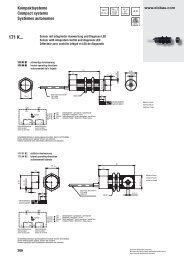
Technische Daten Technical data Caractéristiques techniques Specifiche tecniche <strong>171</strong> <strong>K1</strong> <strong>B1</strong> <strong>171</strong> <strong>K4</strong> <strong>B1</strong> <strong>171</strong> <strong>K1</strong> <strong>B2</strong> <strong>171</strong> <strong>K4</strong> <strong>B2</strong><br />
Betriebsspannung Operating voltage Tension de service Tensione di esercizio 24 V AC/DC ± 10 % 230 V AC ± 10 % 24 V AC/DC ± 10 % 230 V AC ± 10 %<br />
Stromaufnahme Power consumption Consommation de courant Corrente assorbita 50 mA (24 V DC) 50 mA (230 V AC) 50 mA (24 V DC) 50 mA (230 V AC)<br />
Ansteuerung Control Activation Pilotaggio stirnseitig / on the face / face avant / seitlich / on the side / de côté /<br />
frontalmente<br />
lateralmente<br />
Sicherung Betriebsspannung Operating voltage fuse Fusible tension de service Fusibile tensione di esercizio 500 mA<br />
Sicherung Sicherheitsausgang Fuse safety output Fusible sortie de sécurité Fusibile uscita di sicurezza 2,5 A<br />
Sicherung Kontrollausgang Fuse control output Fusible sortie de contrôle Fusibile uscita di controllo 100 mA<br />
max. Schaltspannung Sicherheitsausgang Max. switching voltage safety output Tension de commutation max. sortie de sécurité Max. tensione di collegamento uscita di sicurezza 250 V AC / 30 V DC<br />
max. Schaltstrom Sicherheitsausgang Max. switching current safety output Courant de commutation max. sortie de sécurité Max. corrente di commutazione uscita di sicurezza 2,5 A<br />
max. Schaltleistung Sicherheitsausgang Max. switching capacity safety output Puissance de commutation max. sortie de sécurité Max. potenza di interruzione uscita di sicurezza 625 VA / 75 W<br />
max. Schaltspannung Kontrollausgang Max. switching voltage control output Tension de commutation max. sortie de contrôle Max. tensione di collegamento uscita di controllo 250 V AC / 30 V DC<br />
max. Schaltstrom Kontrollausgang Max. switching current control output Courant de commutation max. sortie de contrôle Max. corrente di commutazione uscita di controllo 100 mA<br />
max. Schaltleistung Kontrollausgang Max. switching capacity control output Puissance de commutation max. sortie de contrôle Max. potenza di interruzione uscita di controllo 25 VA / 3 W<br />
Schutzart International protection Classe de protection Tipo di protezione IP 67<br />
Temperaturbereich Temperature range Plage de température Intervallo di temperatura -25 .... + 70 °C<br />
Mögliche Schaltmagnete<br />
Possible actuation magnets<br />
Aimants de commutation possibles<br />
Possibile magnete di commutazione<br />
304 200 00<br />
(magnetverstärkte Schaltmagnete nur einsetzen, (only use reinforced actuation magnets if a gap of (n'utiliser des aimants de commutation que (inserire un magnete di commutazione rinforzato 304 200 00S<br />
wenn ein größer Luftspalt als 7 mm unabdingbar more than 7 mm is unavoidable)<br />
lorsqu'un entrefer de plus de 7 mm est<br />
solo se un traferro più grande di 7 mm è<br />
ist)<br />
indispensable)<br />
inalienabile)<br />
Einbautoleranz Installation tolerance Tolérance de montage Tolleranza di montaggio ± 2 mm bzw. / or / ou / o ± 5 mm<br />
Gebrauchsdauer Usable life Durée d‘utilisation Durata di utilizzo 20 Jahre / years / ans / anni<br />
Vibrations- und Schockfestigkeit Vibration and shock resistance Résistance aux vibrations et aux chocs Resistenza alle vibrazione e agli urti<br />
Schwingen Vibration Oscillations Oscillazioni 10...55Hz, 1mm<br />
Schocken Shock Chocs Urti 30 g / 11 ms<br />
Dauerschocken Continuous shock Chocs continus Urti continui 10 g / 16 ms<br />
Sicherheitseinstufung Safety classification Classement de sécurité Classificazione in base alla sicurezza<br />
SIL laut IEC/DIN EN 61508 SIL acc. to the IEC/DIN EN 61508 SIL selon IEC/DIN EN 61508 SIL secondo la normativa IEC/DIN EN 61508 2<br />
SILCL laut IEC/DIN EN 62061 SILCL acc. to the IEC/DIN EN 62061 SILCL selon IEC/DIN EN 62061 SILCL secondo la normativa IEC/DIN EN 62061 2<br />
PL laut DIN EN ISO 13849 PL according to DIN EN ISO 13849 PL selon DIN EN ISO 13849 PL secondo la normativa DIN EN ISO 13849 d<br />
Luftspalte (Schaltabstände) für sichere<br />
Gaps (operating distance) for safe switching Entrefers (écarts de commutation) pour une Traferro (distanze di commutazione) per una<br />
Schaltfunktion in mm:<br />
function in mm:<br />
fonction de commutation en mm :<br />
funzione di commutazione in sicurezza in mm:<br />
MIN N<br />
MIN N<br />
MIN N<br />
MIN N<br />
0,5<br />
S<br />
S<br />
S<br />
S<br />
0,5<br />
EIN N<br />
ON N<br />
ACTIVÉ N<br />
ON N<br />
7<br />
S<br />
S<br />
S<br />
S<br />
10<br />
AUS N<br />
OFF N<br />
DÉSACTIVÉ N<br />
OFF N<br />
18<br />
S<br />
S<br />
S<br />
S<br />
21<br />
N = normal MIN. = Mindest-Luftspalt N = normal MIN. = minimum gap N = normal MIN. = entrefer minimum N = normale MIN. = traferro minimo<br />
S = verstärkt<br />
S = reinforced<br />
S = renforcé<br />
S = rinforzato<br />
Einbautoleranz (stirnseitig)<br />
Installation tolerance (on the face)<br />
Tolérance de montage (face avant)<br />
Tolleranza di montaggio (frontalmente)<br />
Einbautoleranz (seitlich)<br />
Installation tolerance (on the side)<br />
Tolérance de montage (de côté)<br />
Tolleranza di montaggio (lateralmente)
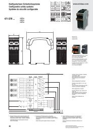
Legende/Legend/Légende/Legenda<br />
1 Schaltbild Circuit diagram Schéma des connexions Schema dell'impianto<br />
2 Technische Zeichnung<br />
<strong>171</strong> <strong>K1</strong> <strong>B1</strong> und <strong>171</strong> <strong>K4</strong> <strong>B1</strong><br />
3 Technische Zeichnung<br />
<strong>171</strong> <strong>K1</strong> <strong>B2</strong> und <strong>171</strong> <strong>K4</strong> <strong>B2</strong><br />
4 Anschlusskabel 6 x 0,34 mm2 , Länge 1000 mm<br />
Betriebsspannung: braun und weiß<br />
Sicherheitsausgang: gelb und grün<br />
Kontrollausgang: rosa und grau<br />
Technical drawing<br />
<strong>171</strong> <strong>K1</strong> <strong>B1</strong> and <strong>171</strong> <strong>K4</strong> <strong>B1</strong><br />
Technical drawing<br />
<strong>171</strong> <strong>K1</strong> <strong>B2</strong> and <strong>171</strong> <strong>K4</strong> <strong>B2</strong><br />
Connecting cable 6 x 0.34 mm 2 , length 1000 mm<br />
Operating voltage: Brown and white<br />
Safety output: Yellow and green<br />
Control output: Pink and grey<br />
Dessin technique<br />
<strong>171</strong> <strong>K1</strong> <strong>B1</strong> et <strong>171</strong> <strong>K4</strong> <strong>B1</strong><br />
Dessin technique<br />
<strong>171</strong> <strong>K1</strong> <strong>B2</strong> et <strong>171</strong> <strong>K4</strong> <strong>B2</strong><br />
Art.-Nr./Art. No./Réf./N° art.: 900585 Version/Version/Version/Versione: 1.3 Datum/Date/Date/Data: 10.02.2011<br />
Câble de raccordement 6 x 0,34 mm 2 , longueur 1000 mm<br />
Tension de service : Marron et blanc<br />
Sortie de sécurité : Jaune et vert<br />
Sortie de contrôle : Rose et gris<br />
Disegno tecnico<br />
<strong>171</strong> <strong>K1</strong> <strong>B1</strong> e <strong>171</strong> <strong>K4</strong> <strong>B1</strong><br />
Disegno tecnico<br />
<strong>171</strong> <strong>K1</strong> <strong>B2</strong> e <strong>171</strong> <strong>K4</strong> <strong>B2</strong><br />
Cavo di collegamento 6 x 0,34 mm 2 , lunghezza 1000 mm<br />
Tensione di esercizio: Marrone e bianco<br />
Uscita di sicurezza: Giallo e verde<br />
Uscita di controllo: Rosa e grigio