Installation Guide - Bosch Security Systems
Installation Guide - Bosch Security Systems
Installation Guide - Bosch Security Systems

Create successful ePaper yourself
Turn your PDF publications into a flip-book with our unique Google optimized e-Paper software.
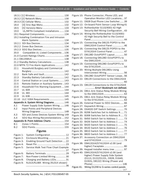
D9412GV4/D7412GV4 v2.03 | <strong>Installation</strong> and System Reference <strong>Guide</strong> | Contents.18.3.1 [1] Wireless .......................................... 13018.3.2 [2] Network Menu ................................ 13018.3.3 [3] Cellular Menu .................................. 13218.4 [4] Srvc Byp Menu ............................... 13218.5 [5] Versions Menu ............................... 13319.0 UL/NFPA Compliant <strong>Installation</strong>s ....... 13419.1 Required Components ............................. 13419.2 Installing Combination Fire and IntrusionAlarm <strong>Systems</strong> ..................................... 13419.2.1 SDI Bus Devices ................................... 13419.2.2 Zonex Bus Devices ............................... 13419.2.3 SDI2 Bus Devices ................................. 13520.0 Compatible UL Listed Components ... 13621.0 Current Ratings Charts ............................ 13821.1 D8125MUX ............................................... 13821.2 Standby Battery Calculations .................. 13822.0 NFPA 72 Fire Alarm Applications ............. 14222.1 Household Burglary and CommercialBurglary ............................................... 14222.2 Bank Safe and Vault ............................. 14222.3 Standby Battery Calculation ................ 14222.4 Central Station or Local <strong>Systems</strong> ........ 14322.5 Remote Station or Auxiliary <strong>Systems</strong> .. 14322.6 Household Fire Warning Equipment .... 14422.7 UL 609 ................................................. 14422.8 UL 365 ................................................. 14422.9 UL 636 ................................................. 14522.10 ULC S304 Requirements ..................... 145Appendix A: System Wiring Diagrams ............... 146A.1 Power Supply Side System Wiring ...... 146A.2 Input Points and Peripheral DevicesWiring Diagrams .................................. 148A.3 SDI and Zonex Devices System Wiring 149A.4 SDI2 Bus Wiring Recommendations .... 152Appendix B: Point Address Charts ................... 154B.1 Zonex 1 Points ..................................... 154B.2 SDI2 Points .......................................... 155FiguresFigure 1: System Configuration ...................... 12Figure 2: Enclosure Mounting ......................... 21Figure 3: Enabling Ground Fault Detection .... 22Figure 4: Reset Pin ......................................... 23Figure 5: Service Walk Test Flow Chart Example......................................................... 27Figure 6: Battery Terminals ............................ 29Figure 7: Non-Power-Limited Wiring ............... 30Figure 8: Charging and Battery LEDs .............. 31Figure 9: RJ31X/RJ38X Wiring (RJ31X shown)......................................................... 36Figure 10: Phone Connector, Phone LED, andOperation Monitor LED Locations ... 37Figure 11: D928 Dual Phone Line Switcher...... 39Figure 12: On-board Point Sensor Loop Wiring 41Figure 13: Rothenbuhler 5110/4001-42 High<strong>Security</strong> Bell Wiring Configuration .. 43Figure 14: Wiring the Rothenbuhler 5110/4001-42 High <strong>Security</strong> Bell to the ControlPanel................................................ 44Figure 15: Connecting the D8125 POPEX to theD9412GV4 Control Panel ................ 46Figure 16: Connecting the D8125 POPEX to theD7412GV4 Control Panel ................ 47Figure 17: D8128D OctoPOPIT Layout ............. 50Figure 18: Connecting D8128D OctoPOPITs tothe D9412GV4 ................................. 53Figure 19: Connecting D8128D OctoPOPITs tothe D7412GV4 ................................. 54Figure 20: Wiring Multiple D8128Ds UsingInterconnect Wiring ......................... 56Figure 21: D8128D OctoPOPIT Sensor Loops .. 56Figure 22: D8129 Connections to the D9412GV4........................................................ 60Figure 23: D8129 Connections to the D7412GV4.............. Error! Bookmark not defined.Figure 24: D811 Arm Status Relay Module Wiringto the D9412GV4 ............................. 63Figure 25: D811 Arm Status Relay Module Wiringto the D7412GV4 ............................. 63Figure 26: External Power to SDI2 Devices ...... 66Figure 27: Keyswitch Wiring ............................. 67Figure 28: DX4020 DIP Switch Settings ........... 70Figure 29: B208 Switches Set to Address 9 ..... 71Figure 30: B308 Switches Set to Address 9 ..... 72Figure 31: B450 Switch Set to Address 1 ........ 73Figure 32: B426 Switch Set to Address 1 ........ 74Figure 33: B420 Switch Set to Address 1 ........ 75Figure 34: B520 Switch Set to Address 2 ........ 76Figure 35: B810 Switch Set to Address 1 ........ 77Figure 36: B820 Switch Set to Address 1 ........ 77Figure 37: Accessory Connection on D9412GV4and D7412GV4 ................................ 79Figure 38: D9412GV4/D7412GV4 v2.00 (andhigher) Faceplate ............................ 80Figure 39: Keypad Installer menu tree ............. 97Figure 40: D9412GV4/D7412GV4 v2.00 (andhigher) Power Supply Side System(D113, D122/D122L, D928, D1640,D192G, D8132) Wiring (Power andPhone) ........................................... 146Figure 41: Wiring D125B to G-series control panels.......................... 147<strong>Bosch</strong> <strong>Security</strong> <strong>Systems</strong>, Inc. | 4/14 | F01U265457-05 6