600346029 DTM04 Dometic tank monitor system manual
600346029 DTM04 Dometic tank monitor system manual
600346029 DTM04 Dometic tank monitor system manual

You also want an ePaper? Increase the reach of your titles
YUMPU automatically turns print PDFs into web optimized ePapers that Google loves.
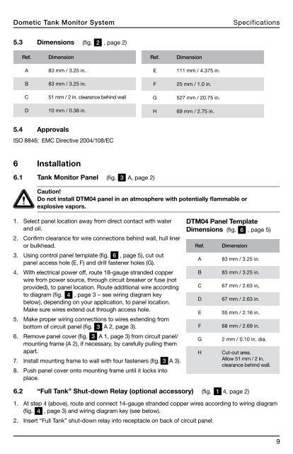
<strong>Dometic</strong> Tank Monitor SystemSpecifications5.3 Dimensions (fig. 2, page 2)Ref.DimensionRef.DimensionA83 mm / 3.25 in.E111 mm / 4.375 in.B83 mm / 3.25 in.F25 mm / 1.0 in.C51 mm / 2 in. clearance behind wallG527 mm / 20.75 in.D10 mm / 0.38 in.H69 mm / 2.75 in.5.4 ApprovalsISO 8846; EMC Directive 2004/108/EC6 Installation6.1 Tank Monitor Panel (fig. 3A, page 2)Caution!Do not install <strong>DTM04</strong> panel in an atmosphere with potentially flammable orexplosive vapors.1. Select panel location away from direct contact with waterand oil.2. Confirm clearance for wire connections behind wall, hull lineror bulkhead.3. Using control panel template (fig. 86, page 5), cut outpanel access hole (E, F) and drill fastener holes (G).4. With electrical power off, route 18-gauge stranded copperwire from power source, through circuit breaker or fuse (notprovided), to panel location. Route additional wire accordingto diagram (fig. 4 , page 3 – see wiring diagram keybelow), depending on your application, to panel location.Make sure wires extend out through access hole.5. Make proper wiring connections to wires extending frombottom of circuit panel (fig. 43 3 A 2, page 3).6. Remove panel cover (fig. 3A 1, page 3) from circuit panel/mounting frame (A 2), if necessary, by carefully pulling themapart.7. Install mounting frame to wall with four fasteners (fig. 3A 3).8. Push panel cover onto mounting frame until it locks intoplace.<strong>DTM04</strong> Panel TemplateDimensions (fig. 6x , page 5)Ref.ABCDEFGHDimension83 mm / 3.25 in.83 mm / 3.25 in.67 mm / 2.63 in,67 mm / 2.63 in.55 mm / 2.16 in.68 mm / 2.69 in.2 mm / 0.10 in. dia.Cut-out area.Allow 51 mm / 2 in.clearance behind wall.6.2 “Full Tank” Shut-down Relay (optional accessory) (fig. 14, page 2)1. At step 4 (above), route and connect 14-gauge stranded copper wires according to wiring diagram(fig. 4, page 3) and wiring diagram key (see below).2. Insert “Full Tank” shut-down relay into receptacle on back of circuit panel.9