Preaction System with Model DV-5 Deluge Valve - Tyco Fire Products
Preaction System with Model DV-5 Deluge Valve - Tyco Fire Products
Preaction System with Model DV-5 Deluge Valve - Tyco Fire Products

You also want an ePaper? Increase the reach of your titles
YUMPU automatically turns print PDFs into web optimized ePapers that Google loves.
Customer Service/Sales:<br />
Technical Services: Tel: http://www.tyco-fireproducts.com<br />
(800) 381-9312 / Fax: (800) 791-5500<br />
Tel: (414) 570-5000 / (800) 558-5236<br />
Fax: (414) 570-5010 / (800) 877-1295<br />
Sistema <strong>Preaction</strong> de <strong>System</strong> Pré-acção <strong>with</strong> de Interbloqueio <strong>Model</strong> <strong>DV</strong>-5 <strong>Deluge</strong> Simples<br />
<strong>Valve</strong><br />
Supervisionado Single Interlock, com Supervised Válvula de — Dilúvio Wet Pilot <strong>Model</strong>o Actuation <strong>DV</strong>-5—<br />
Actuação 1-1/2 thruPiloto 8 Inch Hidráulica (DN40 thru DN40 DN200) até DN200 (1-1/2 até 8”)<br />
Descrição General Geral<br />
Description<br />
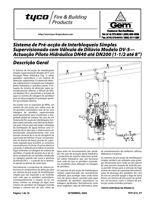
O Sistema de Pré-acção de Interbloqueio<br />
Simples The <strong>Model</strong> Supervisionado <strong>DV</strong>-5 Supervised <strong>Model</strong>o Single <strong>DV</strong>-5 com<br />
Interlock<br />
<strong>Preaction</strong> Piloto Hidráulica <strong>System</strong> (Fig. <strong>with</strong> 1) Wet utiliza<br />
Pi-<br />
Actuação sprinklers lot Actuation automáticos (Fig. 1) utilizes e um automatic<br />
sistema de<br />
detecção sprinklers suplementar. and a supplemental O sistema de detection<br />
detecção<br />
suplementar system. The<br />
é composto supplemental<br />
por tubagens<br />
detection<br />
system<br />
piloto hidráulicas is comprised<br />
e sprinklers of<br />
piloto. wet pilot<br />
A ac-<br />
lines and pilot sprinklers. Actuation of<br />
tuação do sistema de detecção opera au-<br />
the detection system automatically operates<br />
(releases)<br />
tomaticamente (liberta) the <strong>Model</strong><br />
a Válvula <strong>DV</strong>-5<br />
de <strong>Deluge</strong><strong>Model</strong>o<br />
<strong>Valve</strong>, <strong>DV</strong>-5, allowing permitindo water to a entrada flow into da<br />
Dilúvio<br />
água the sprinkler no sistema piping de tubagem systemde and sprinklers<br />
to be<br />
para discharged ser descarregada from any em quaisquer sprinklers sprink-<br />
that<br />
lers may que beestejam open. abertos.<br />
De In acordo accordance com os <strong>with</strong> requisitos the requirements<br />
da NFPA, um<br />
sistema of the National de pré-acção <strong>Fire</strong> que Protection utilize mais Association,<br />
sprinklers a preaction automáticos system employing<br />
de ter uma<br />
de<br />
20 tubagem more thande 20 automatic sprinklers sprinklers supervisionada<br />
to<br />
automaticamente have the sprinkler para piping monitorizar automatically a integridade<br />
supervised global todo monitor sistema. the No overall caso de integrity<br />
de of Pré-acção the system. de Interbloqueio the case of Sim-<br />
a<br />
um<br />
Sistema ples Supervised Supervisionado, Singleuma Interlock Válvula <strong>Preaction</strong> de Retenção<br />
<strong>System</strong>, para Coluna a Riser (que Check não exige <strong>Valve</strong> a utilização<br />
(that<br />
de does<br />
bombagem not require<br />
de água) the use<br />
fornece of priming<br />
uma regulação<br />
water)<br />
do provides<br />
ar para an<br />
que air<br />
o sistema check<br />
possa so that<br />
ser<br />
the system can be automatically pressurized<br />
<strong>with</strong> a nominal supervisory air<br />
pressurizado automaticamente com uma<br />
pressão or nitrogen<br />
nominal pressure<br />
de ar ou of<br />
de 10<br />
nitrogénio psi (0,69<br />
de<br />
supervisão bar). A supervisory<br />
de 0,69 bar low<br />
(10 pressure<br />
psi). Um pressós-<br />
alarm<br />
tato switch de that alarme is set de to baixa transfer pressão its contacts de supervisão<br />
at nominally regulado 5para psi transferir (0,34 bar), os contactos<br />
decreasing<br />
pressure, a 0,34 bar is (5 utilized psi) ao to diminuir<br />
indi-<br />
nominalmente a cate pressão, whether é utilizado therepara areindicar any abnormal se existem<br />
fugas leaksanómalas in the sprinkler na tubagem system do sistema piping. de água antes do funcionamento dos sprinklers.<br />
as a of a damaged sprinkler or<br />
system<br />
de armazenamento de artefactos valiosos,<br />
sprinklers. Loss of air A perda pressure de pressão from the de ar system do sis-<br />
the case of wet pilot actuation, the<br />
also effectively used to protect properties<br />
where<br />
No caso designer<br />
de actuação selects<br />
piloto wet<br />
hidráulica,<br />
pilot<br />
bibliotecas e arquivos.<br />
tema resultante de um sprinkler danificado<br />
a pre-alarm of a possible<br />
o broken piping will not cause the <strong>DV</strong>-5<br />
sprinklers projectista that do sistema will operate selecciona sooner sprinklers<br />
<strong>Valve</strong> to open the air pressure is for<br />
thepiloto automatic hidráulicos sprinklers que vão chosen funcionar<br />
ou tubagem partida não causa a abertura<br />
than<br />
fire condition may allow time for fire<br />
Os sistemas de pré-acção de interbloqueio<br />
da Válvula <strong>DV</strong>-5 — a pressão do ar destina-<br />
for<br />
extinguishment by alternate suppression<br />
means, prior to a sprinkler dis-<br />
mais supervisory only.<br />
use cedo on thedo sprinkler que os sprinklers piping. automáticos<br />
escolhidos para utilização na tubagem<br />
simples também são utilizados para proteger<br />
eficazmente bens onde um pré-alarme<br />
charge. In the event the fire cannot<br />
Typically, the system designer selects<br />
Supervised single interlock preaction<br />
se apenas ao alarme de supervisão.<br />
Normalmente, o projectista do sistema selecciona<br />
os componentes de detecção para<br />
tion sprinkler system will then perform<br />
interlock preaction system that will re-<br />
Os areas sistemas where de there pré-acção is danger de interbloqueio<br />
of serious através de meios de supressão alternativos,<br />
de sprinklers.<br />
de uma possível situação de incêndio pos-<br />
otherwise be extinguished, the preac-<br />
the detection components for a single<br />
systems are generally used to protect sa permitir tempo para a extinção do fogo<br />
um sistema de pré-acção de interbloqueio<br />
as the primary fire protection system.<br />
spond to a fire sooner than the automatic<br />
sprinklers. Consequently, the utilizados damagedpara automatic proteger sprinklers áreas onde orexista<br />
pip-<br />
de The não <strong>Model</strong> ser possível <strong>DV</strong>-5 apagar <strong>Deluge</strong> o fogo <strong>Valve</strong> de outra<br />
(de-<br />
simples water damage supervisionado that might são normalmente<br />
result from antes da descarga dos sprinklers. No caso<br />
simples que vão responder a um incêndio<br />
mais cedo que os sprinklers automáticos.<br />
system will experience a minimal delay risco ing. Typically, de graves such danos areas causados include pela computer<br />
rooms, de sprinklers storage areas automáticos for valu-<br />
ou lers TFP1305) vai funcionar is a diaphragm como o sistema stylede valve pro-<br />
água forma, scribed um sistema in Technical de pré-acção Datade Sheet sprink-<br />
Consequentemente, in water delivery over<br />
o sistema that for<br />
vai ter a wet<br />
um resultantes atraso pipe sprinkler<br />
mínimo na system<br />
entrega because<br />
da água num<br />
the tubagem able artifacts, danificados. libraries, Normalmente, and archives. essas tecção that depends contra incêndios upon water primário.<br />
pressure in<br />
sistema systemde will sprinklers have essentially de tubagem filled húmida<br />
<strong>with</strong> áreas the Diaphragm Chamber to hold the<br />
Single englobam interlock salas preaction de informática, systemsáreas<br />
are<br />
porque water before o sistema a sprinkler tem de estar operates. cheio In de<br />
(TEXTO CONTINUA (TEXT CONTINUED NA PÁGINA ON9)<br />
PAGE 9)<br />
Página 1 de 16 Page of 16<br />
SEPTEMBER,<br />
SETEMBRO, 2004 2004<br />
TFP1410_PT<br />
TFP1410
Página Page 2de of 16 16<br />
TFP1410_PT<br />
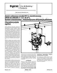
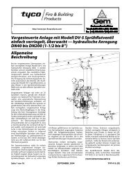
1 - Válvula de Dilúvio <strong>Model</strong>o <strong>DV</strong>-5<br />
2 - Válvula de Controlo Principal (N.A.)<br />
3 - Válvula de Controlo de Fornecimento<br />
da Câmara do Diafragma (N.A.)<br />
4 - Posto de Controlo Manual Local<br />
5 - Sprinklers automáticos<br />
6 - Sprinklers de Tubagem Piloto<br />
Hidráulica (Detecção de Incêndios)<br />
7 - Manómetro do Fornecimento de Água<br />
8 - Manómetro da Câmara do Diafragma<br />
9 - Válvula de Drenagem do Sistema (N.F.)<br />
10 - Válvula de Drenagem Principal (N.F.)<br />
(Mostrada na Traseira da Válvula)<br />
11 - Válvula de Seccionamento Automático<br />
da Câmara do Diafragma<br />
12 - Pressóstato de Alarme de Débito<br />
(Mostrado na Traseira da Válvula)<br />
13 - Alarme de Motor Hidráulico (Opcional)<br />
14 - Válvula de Retenção para Coluna<br />
15- Manómetro de Ar de Supervisão<br />
16 - Fornecimento de Ar/Nitrogénio<br />
de Supervisão Automático<br />
17 - Pressóstato de Alarme de Baixa<br />
Pressão de Supervisão<br />
FIGURA 1 — PARTE 1 DE 2<br />
SISTEMA DE PRÉ-ACÇÃO DE INTERBLOQUEIO SIMPLES SUPERVISIONADO COM ACTUAÇÃO PILOTO HIDRÁULICA<br />
— ESQUEMA DO SISTEMA (Vista Dianteira) —
TFP1410_PT Page Página 3 of de 16 16<br />
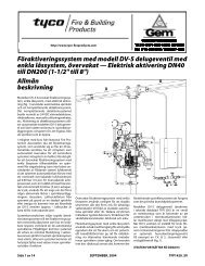
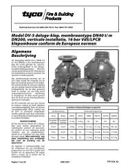
1 - Válvula de Dilúvio <strong>Model</strong>o <strong>DV</strong>-5<br />
2 - Válvula de Controlo Principal (N.A.)<br />
3 - Válvula de Controlo de Fornecimento<br />
da Câmara do Diafragma (N.A.)<br />
4 - Posto de Controlo Manual Local<br />
(Mostrado na Dianteira da Válvula)<br />
5 - Sprinklers automáticos<br />
6 - Sprinklers de Tubagem Piloto<br />
Hidráulica (Detecção de Incêndios)<br />
7 - Manómetro do Fornecimento de Água<br />
(Mostrado na Dianteira da Válvula)<br />
8 - Manómetro da Câmara do Diafragma<br />
(Mostrado na Dianteira da Válvula)<br />
9 - Válvula de Drenagem do Sistema (N.F.)<br />
10 - Válvula de Drenagem Principal (N.F.)<br />
11 - Válvula de Seccionamento Automático<br />
da Câmara do Diafragma<br />
12 - Pressóstato de Alarme de Débito<br />
13 - Alarme de Motor Hidráulico (Opcional)<br />
14 - Válvula de Retenção para Coluna<br />
15 - Manómetro de Ar de Supervisão<br />
(Mostrado na Dianteira da Válvula)<br />
16 - Fornecimento de Ar/Nitrogénio<br />
de Supervisão Automático<br />
17 - Pressóstato de Alarme de Baixa<br />
Pressão de Supervisão<br />
FIGURA 1 — PARTE 2 DE 2<br />
SISTEMA DE PRÉ-ACÇÃO DE INTERBLOQUEIO SIMPLES SUPERVISIONADO COM ACTUAÇÃO PILOTO HIDRÁULICA<br />
— ESQUEMA DO SISTEMA (Vista Traseira) —
Página de 16<br />
TFP1410_PT<br />
Nº DESCRIÇÃO QTD P/N<br />
Page 4 of 16<br />
1 Manómetro de Água 20 bar/<br />
300 psi . . . . . . . . . . . . . . . . . . . . . . . . . 2 92-343-1-005<br />
2 Válvula de Teste do Manómetro<br />
1/4” . . . . . . . . . . . . . . . . . . . . . . . . . . . . 1 46-005-1-002<br />
3 Posto de Controlo Manual <strong>Model</strong>o<br />
MC-1 . . . . . . . . . . . . . . . . . . . . . . . . 1 52-289-2-001<br />
4 Válvula de Drenagem Automática<br />
<strong>Model</strong>o AD-1 . . . . . . . . . . . . . . . . . . . 1 52-793-2-004<br />
5 Válvula de Seccionamento Automático<br />
<strong>Model</strong>o ASV-1. . . . . . . . . . . 1 92-343-1-021<br />
6 Pressóstato de Alarme de Débito<br />
(PS10-2A) . . . . . . . . . . . . . . . . . . . . . . 1 2571<br />
7 Válvula de Esfera 1/2” . . . . . . . . . . . 2 46-050-1-004<br />
8 Válvula de Retenção com Mola<br />
1/2” . . . . . . . . . . . . . . . . . . . . . . . . . . . . 1 92-322-1-002<br />
9 Filtro Y 1/2”. . . . . . . . . . . . . . . . . . . . . 1 52-353-1-005<br />
10 Válvula de Retenção de Batente<br />
3/4” . . . . . . . . . . . . . . . . . . . . . . . . . . . . 1 46-049-1-005<br />
11 Válvula em Ângulo 3/4”. . . . . . . . . 1 46-048-1-005<br />
12 Funil de drenagem . . . . . . . . . . . . . 1 92-211-1-005<br />
13 Suporte do Funil de Drenagem . 1 92-211-1-003<br />
14 Funil de Drenagem . . . . . . . . . . . . . 1 92-343-1-007<br />
15 Elemento de Purga 3/32”. . . . . . . . 1 92-032-1-002<br />
16 Tubagem 1/4” x 18” . . . . . . . . . . . . . 1 CH<br />
17 Colector 1/2” . . . . . . . . . . . . . . . . . . . 1 CH<br />
18 Tubagem 1/2” x 12” . . . . . . . . . . . . . 1 CH<br />
19 Tampão 1/4”. . . . . . . . . . . . . . . . . . . . 1 CH<br />
Nº DESCRIÇÃO QTD P/N<br />
20 Tampão 3/4”. . . . . . . . . . . . . . . . . . . . 1 CH<br />
21 União 1/2”. . . . . . . . . . . . . . . . . . . . . . 5 CH<br />
22 União 3/4”. . . . . . . . . . . . . . . . . . . . . . 1 CH<br />
23 Cotovelo1/4” 90° . . . . . . . . . . . . . . . 1 CH<br />
24 Cotovelo1/2” 90° . . . . . . . . . . . . . . . 7 CH<br />
25 Cotovelo3/4” 90° . . . . . . . . . . . . . . . 1 CH<br />
26 Cotovelo3/4” x 1/2” 90° . . . . . . . . . 1 CH<br />
27 União T 1/2” . . . . . . . . . . . . . . . . . . . . 3 CH<br />
28 União T 1/2” x 1/4” x 1/2” . . . . . . . . 3 CH<br />
29 União T 3/4” . . . . . . . . . . . . . . . . . . . . 1 CH<br />
30 União T 3/2” x 1/4” x 3/4” . . . . . . . . 2 CH<br />
31 Vedante de União Roscada 1/4” . 2 CH<br />
32 Vedante de União Roscada 1/2” . 3 CH<br />
33 União Roscada 1/2” x 1-1/2”. . . . . 11 CH<br />
34 União Roscada 1/2” x 2”. . . . . . . . . 1 CH<br />
35 União Roscada 1/2” x 2-1/2”. . . . . 3 CH<br />
36 União Roscada 1/2” x 5”. . . . . . . . . 2 CH<br />
37 União Roscada 1/2” x 7”. . . . . . . . . 1 CH<br />
38 Seleccionar União Rosc. pela tab. 2 CH<br />
39 Seleccionar União Rosc. pela tab. 2 CH<br />
40 União Roscada 3/4” x 1-1/2”. . . . . 6 CH<br />
41 União Roscada 3/4” x 2”. . . . . . . . . 1 CH<br />
42 União Roscada 3/4” x 4”. . . . . . . . . 1 CH<br />
P1 Manómetro de Ar 17,5 bar/<br />
250 psi . . . . . . . . . . . . . . . . . . . . . . . . . 1 92-343-1-012<br />
Nº DESCRIÇÃO QTD P/N<br />
P2 Válvula de Teste do Manómetro<br />
1/4” . . . . . . . . . . . . . . . . . . . . . . . . . . . . 1 46-005-1-002<br />
P3 Pressóstato de Alarme de Baixa<br />
Pressão (PS10-2A) . . . . . . . . . . . . . . 1 2571<br />
P4 Válvula de alívio de pressão 1/4” 1 92-343-1-019<br />
P5 Válvula de Retenção de Batente<br />
1/2” . . . . . . . . . . . . . . . . . . . . . . . . . . . . 1 46-049-1-004<br />
P6 Válvula de Globo 1/2”. . . . . . . . . . . 1 46-047-1-004<br />
P7 Válvula em Ângulo 3/4”. . . . . . . . . 1 46-048-1-007<br />
P8 Tampão 1/4”. . . . . . . . . . . . . . . . . . . . 3 CH<br />
P9 Redução Macho-Fêmea 1/2” x 1/4”1 CH<br />
P10 União 1/2”. . . . . . . . . . . . . . . . . . . . . . 1 CH<br />
P11 Cotovelo1/2” 90° . . . . . . . . . . . . . . . 1 CH<br />
P12 Cruzeta 1/2” . . . . . . . . . . . . . . . . . . . . 1 CH<br />
P13 União T 1/2” x 1/2” x 1/4” . . . . . . . . 1 CH<br />
P14 União T 1” x 3/4” x 1/2” . . . . . . . . . . 1 CH<br />
P15 União Roscada 1/4” x 3”. . . . . . . . . 1 CH<br />
P16 União Roscada 1/2” x 1-1/2”. . . . . 5 CH<br />
P17 União Roscada 1/2” x 2-1/2”. . . . . 1 CH<br />
P18 União Roscada 3/4” x 1-1/2”. . . . . 1 CH<br />
P19 União Roscada 1” x 2” . . . . . . . . . . . 1 CH<br />
TFP1410<br />
Seleccionar Tamanho União Roscada<br />
Nº União por Tamanho Válvula Dilúvio <strong>DV</strong>-5<br />
Roscada DN40<br />
(1-1/2”)<br />
DN50<br />
(2”)<br />
38 vedante 1/2” 1/2” x 2“<br />
39 1/2” x 5” 1/2” x 5-1/2”<br />
(TOM<br />
VERDE)<br />
LOCALIZAÇÃO<br />
PARA VÁLVULA<br />
DE CONTROLO<br />
DE ALARME N.A.<br />
DE SUPERVISÃO<br />
ELÉCTRICA<br />
OPCIONAL (BVS‐3/4”)<br />
VÁLVULA DE<br />
RETENÇÃO<br />
PARA<br />
COLUNA<br />
(NOTA 2)<br />
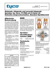
NOTAS:<br />
1. Pré-acção de Interbloqueio<br />
Simples Supervisionado<br />
com Acessórios de<br />
Actuação Piloto Hidráulica<br />
engloba Itens 1-42<br />
mais Itens P1-P19.<br />
2. Utilize apenas a Válvula<br />
de Retenção para Coluna<br />
de 2” <strong>Model</strong>o CV-1FR para<br />
montagens de 1-1/2” ou 2”.<br />
3. Todas as Juntas e Uniões<br />
Roscadas são galvanizadas<br />
(Encomenda Padrão).<br />
4. CH: Ferragens Normais.<br />
MOSTRADA VÁLVULA<br />
DILÚVIO MODELO<br />
<strong>DV</strong>‐5 RANHURA x<br />
RANHURA DN50 (2”)<br />
FIGURA 2A — PARTE 1 DE 3<br />
VÁLVULAS DILÚVIO MODELO <strong>DV</strong>-5 DN40 e DN50 (1-1/2 e 2”)<br />
NOTAS:<br />
5. Consulte Figura 2 de TFP1305<br />
para identificação do Orifício<br />
da Válvula de Dilúvio.<br />
6. Oriente toda a Tubagem para<br />
o Funil de Drenagem, Item 14.<br />
PRÉ-ACÇÃO DE INTERBLOQUEIO SIMPLES SUPERVISIONADO COM ACESSÓRIOS DE ACTUAÇÃO PILOTO HIDRÁULICA<br />
(52-478-X-117)<br />
—VISTA EXPLODIDA—
TFP1410_PT Página de 16 Página TFP1410_PT de 16<br />
Nº DESCRIÇÃO QTD P/N<br />
1 Manómetro de Água 20 bar/<br />
300 psi . . . . . . . . . . . . . . . . . . . . . . . . . . 2 92-343-1-005<br />
2 Válvula de Teste do Manómetro<br />
1/4” . . . . . . . . . . . . . . . . . . . . . . . . . . . . . 1 46-005-1-002<br />
3 Posto de Controlo Manual <strong>Model</strong>o<br />
MC-1. . . . . . . . . . . . . . . . . . . . . . . . . . . . 1 52-289-2-001<br />
4 Válvula de Drenagem Automática<br />
<strong>Model</strong>o AD-1 1 52-793-2-004<br />
5 Válvula de Seccionamento Automático<br />
<strong>Model</strong>o ASV-1. . . . . . . . . . . . 1 92-343-1-021<br />
6 Pressóstato de Alarme de Débito<br />
(PS10-2A) . . . . . . . . . . . . . . . . . . . . . . . 1 2571<br />
7 Válvula de Esfera 1/2” . . . . . . . . . . . . 2 46-050-1-004<br />
8 Válvula de Retenção com Mola 1/2” 1 92-322-1-002<br />
9 Filtro Y 1/2”. . . . . . . . . . . . . . . . . . . . . . 1 52-353-1-005<br />
10 Válvula de Retenção de Batente<br />
3/4” . . . . . . . . . . . . . . . . . . . . . . . . . . . . . 1 46-049-1-005<br />
11 Válvula em Ângulo 1-1/4” . . . . . . . . 1 46-048-1-007<br />
12 Funil de drenagem . . . . . . . . . . . . . . 1 92-211-1-005<br />
13 Suporte do Funil de Drenagem . 1 92-211-1-003<br />
14 Funil de Drenagem . . . . . . . . . . . . . 1 92-343-1-007<br />
15 Elemento de Purga 3/32”. . . . . . . . 1 92-032-1-002<br />
16 Tubagem 1/4” x 18” . . . . . . . . . . . . . 1 CH<br />
17 Colector 1/2” . . . . . . . . . . . . . . . . . . . 1 CH<br />
18 Tubagem 1/2” x 18” 1 CH<br />
19 Tampão 1/4”. . . . . . . . . . . . . . . . . . . . 1 CH<br />
20 Tampão 3/4”. . . . . . . . . . . . . . . . . . . . 1 CH<br />
TFP1410<br />
Nº DESCRIÇÃO QTD P/N<br />
21 União 1/2”. . . . . . . . . . . . . . . . . . . . . . 5 CH<br />
22 União 3/4”. . . . . . . . . . . . . . . . . . . . . . 1 CH<br />
23 Cotovelo1/4” 90° . . . . . . . . . . . . . . . 1 CH<br />
24 Cotovelo1/2” 90° . . . . . . . . . . . . . . . 7 CH<br />
25 Cotovelo3/4” x 1/2” 90° . . . . . . . . . 1 CH<br />
26 Cotovelo1-1/4” 90°. . . . . . . . . . . . . . 1 CH<br />
27 União T 1/2” . . . . . . . . . . . . . . . . . . . . 3 CH<br />
28 União T 1/2” x 1/4” x 1/2” . . . . . . . . 3 CH<br />
29 União T 3/4” . . . . . . . . . . . . . . . . . . . . 1 CH<br />
30 União T 3/4” x 1/2” x 3/4” . . . . . . . . 2 CH<br />
31 Vedante de União Roscada 1/4” . 2 CH<br />
32 Vedante de União Roscada 1/2” . 2 CH<br />
33 União Roscada 1/2” x 1-1/2”. . . . . 13 CH<br />
34 União Roscada 1/2” x 2-1/2”. . . . . 1 CH<br />
35 União Roscada 1/2” x 3-1/2”. . . . . 1 CH<br />
36 União Roscada 1/2” x 4”. . . . . . . . . 1 CH<br />
37 União Roscada 1/2” x 4-1/2”. . . . . 1 CH<br />
38 União Roscada 1/2” x 5”. . . . . . . . . 1 CH<br />
39 União Roscada 1/2” x 5-1/2”. . . . . 1 CH<br />
40 União Roscada 1/2” x 7”. . . . . . . . . 2 CH<br />
41 União Roscada 3/4” x 1-1/2”. . . . . 5 CH<br />
42 União Roscada 3/4” x 2”. . . . . . . . . 1 CH<br />
43 União Roscada 1-1/4” x 2” . . . . . . . 1 CH<br />
44 União Roscada 1-1/4” x 4” . . . . . . . 1 CH<br />
Nº DESCRIÇÃO QTD P/N<br />
P1 Manómetro de Ar 17,5 bar/250 psi<br />
1 92-343-1-012<br />
P2 Válvula de Teste do Manómetro Page 5 of 16<br />
1/4” . . . . . . . . . . . . . . . . . . . . . . . . . . . . 1 46-005-1-002<br />
P3 Pressóstato de Alarme de Baixa<br />
Pressão (PS10-2A) . . . . . . . . . . . . . . 1 2571<br />
P4 Válvula de alívio de pressão 1/4” 1 92-343-1-019<br />
P5 Válvula de Retenção de Batente<br />
1/2” . . . . . . . . . . . . . . . . . . . . . . . . . . . . 1 46-049-1-004<br />
P6 Válvula de Globo 1/2”. . . . . . . . . . . 1 46-047-1-004<br />
P7 Válvula em Ângulo 1-1/4” . . . . . . . 1 46-048-1-007<br />
P8 Tampão 1/4”. . . . . . . . . . . . . . . . . . . . 3 CH<br />
P9 Redução Macho-Fêmea 1/2” x 1/4”<br />
1 CH<br />
P10 União 1/2”. . . . . . . . . . . . . . . . . . . . . . 1 CH<br />
P11 Cotovelo1/2” 90° . . . . . . . . . . . . . . . 1 CH<br />
P12 Cruzeta 1/2” . . . . . . . . . . . . . . . . . . . . 1 CH<br />
P13 União T 1/2” x 1/2” x 1/4” . . . . . . . . 1 CH<br />
P14 União T 1-1/4” x 1-1/4” x 1/2” . . . . 1 CH<br />
P15 União Roscada 1/4” x 3”. . . . . . . . . 1 CH<br />
P16 União Roscada 1/2” x 1-1/2”. . . . . 6 CH<br />
P17 União Roscada 1-1/4” x 2” . . . . . . . 1 CH<br />
P18 União Roscada 1-1/4” x 3” . . . . . . . 1 CH<br />
(TOM<br />
VERDE)<br />
LOCALIZAÇÃO<br />
PARA VÁLVULA<br />
DE CONTROLO<br />
DE ALARME N.A.<br />
DE SUPERVISÃO<br />
ELÉCTRICA<br />
OPCIONAL (BVS-3/4”)<br />
ORIFÍCIOS<br />
TAMPÃO NÃO<br />
UTILIZADOS<br />
VÁLVULA DE<br />
RETENÇÃO<br />
PARA COLUNA<br />
(NOTA 2)<br />
NOTAS:<br />
1. Pré-acção de<br />
Interbloqueio Simples<br />
Supervisionado com<br />
Acessórios de Actuação<br />
Piloto Hidráulica<br />
engloba Itens 1‐44<br />
mais Itens P1-P18.<br />
2. Utilize apenas a Válvula<br />
de Retenção para Coluna<br />
<strong>Model</strong>o CV-1FR.<br />
3. Todas as Juntas e Uniões<br />
Roscadas são galvanizadas<br />
(Encomenda Padrão).<br />
4. CH: Ferragens Normais.<br />
MOSTRADA VÁLVULA<br />
DILÚVIO MODELO<br />
<strong>DV</strong>-5 RANHURA x<br />
RANHURA DN80 (3”)<br />
NOTAS:<br />
5. Consulte Figura 2 de TFP1305<br />
para identificação do Orifício<br />
da Válvula de Dilúvio.<br />
6. Oriente toda a Tubagem<br />
para o Funil de<br />
Drenagem, Item 14.<br />
FIGURA 2A — PARTE 2 DE 3<br />
VÁLVULAS DILÚVIO MODELO <strong>DV</strong>-5 DN80 (3”)<br />
PRÉ-ACÇÃO DE INTERBLOQUEIO SIMPLES SUPERVISIONADO COM ACESSÓRIOS DE ACTUAÇÃO PILOTO HIDRÁULICA<br />
(52-478-X-114)<br />
—VISTA EXPLODIDA—
Página de 16<br />
TFP1410_PT<br />
Nº DESCRIÇÃO QTD P/N<br />
1 Manómetro de Água 20 bar/<br />
300 psi . . . . . . . . . . . . . . . . . . . . . . . . . 2 92-343-1-005<br />
2 Válvula de Teste do Manómetro<br />
1/4” . . . . . . . . . . . . . . . . . . . . . . . . . . . . 1 46-005-1-002<br />
3 Posto de Controlo Manual <strong>Model</strong>o<br />
MC-1 . . . . . . . . . . . . . . . . . . . . . . . . 1 52-289-2-001<br />
4 Válvula de Drenagem Automática<br />
<strong>Model</strong>o AD-1 . . . . . . . . . . . . . . . . . . . 1 52-793-2-004<br />
5 Válvula de Seccionamento Automático<br />
<strong>Model</strong>o ASV-1. . . . . . . . . . . 1 92-343-1-021<br />
6 Pressóstato de Alarme de Débito<br />
(PS10-2A) . . . . . . . . . . . . . . . . . . . . . . 1 2571<br />
7 Válvula de Esfera 1/2” . . . . . . . . . . . 2 46-050-1-004<br />
8 Válvula de Retenção com Mola<br />
1/2” . . . . . . . . . . . . . . . . . . . . . . . . . . . . 1 92-322-1-002<br />
9 Filtro Y 1/2”. . . . . . . . . . . . . . . . . . . . . 1 52-353-1-005<br />
10 Válvula de Retenção de Batente<br />
3/4” . . . . . . . . . . . . . . . . . . . . . . . . . . . . 1 46-049-1-005<br />
11 Não utilizada . . . . . . . . . . . . . . . . . . . 0 N/D<br />
12 Válvula em Ângulo 2” . . . . . . . . . . . 1 46-048-1-009<br />
13 Funil de drenagem . . . . . . . . . . . . . 1 92-211-1-005<br />
14 Suporte do Funil de Drenagem . 1 92-211-1-003<br />
15 Funil de Drenagem . . . . . . . . . . . . . 1 92-343-1-007<br />
16 Elemento de Purga 3/32”. . . . . . . . 1 92-032-1-002<br />
17 Tubagem 1/4” x 24” 1 CH<br />
18 Colector 1/2” . . . . . . . . . . . . . . . . . . . 1 CH<br />
19 Tubagem 1/2” x 24” . . . . . . . . . . . . . 1 CH<br />
20 Tampão 1/4”. . . . . . . . . . . . . . . . . . . . 1 CH<br />
21 Tampão 3/4”. . . . . . . . . . . . . . . . . . . . 1 CH<br />
22 União 1/2”. . . . . . . . . . . . . . . . . . . . . . 5 CH<br />
23 União 1”. . . . . . . . . . . . . . . . . . . . . . . . 1 CH<br />
(TOM<br />
VERDE)<br />
Nº DESCRIÇÃO QTD P/N<br />
24 Cotovelo1/4” 90° . . . . . . . . . . . . . . . 1 CH<br />
25 Cotovelo1/2” 90° . . . . . . . . . . . . . . . 7 CH<br />
26 União T 1/2” . . . . . . . . . . . . . . . . . . . . 3 CH<br />
27 União T 1/2” x 1/2” x 1/4” . . . . . . . . 3 CH<br />
28 União T 3/4” x 1/2” x 3/4” . . . . . . . . 2 CH<br />
29 Cotovelo1” x 1/2” 90°. . . . . . . . . . . . 1 CH<br />
30 União T 1” x 3/4” x 1” . . . . . . . . . . . . 1 CH<br />
31 Cotovelo2” 90°. . . . . . . . . . . . . . . . . . 1 CH<br />
32 Vedante de União Roscada 1/4” . 2 CH<br />
33 Vedante de União Roscada 1/2” . 2 CH<br />
34 União Roscada 1/2” x 1-1/2”. . . . . 10 CH<br />
35 União Roscada 1/2” x 2-1/2”. . . . . 2 CH<br />
36 União Roscada 1/2” x 3”. . . . . . . . . 1 CH<br />
37 União Roscada 1/2” x 5”. . . . . . . . . 2 CH<br />
38 União Roscada 1/2” x 6”. . . . . . . . . 1 CH<br />
39 União Roscada 1/2” x 7”. . . . . . . . . 2 CH<br />
40 Seleccionar União Rosc. pela tab. 2 CH<br />
41 Seleccionar União Rosc. pela tab. 2 CH<br />
42 Seleccionar União Rosc. pela tab. 2 CH<br />
43 União Roscada 3/4” x 1-1/2”. . . . . 1 CH<br />
44 União Roscada 3/4” x 2”. . . . . . . . . 1 CH<br />
45 Seleccionar União Rosc. pela tab. 2 CH<br />
46 União Roscada 1” vedante . . . . . . 2 CH<br />
47 União Roscada 1” x 3” . . . . . . . . . . . 1 CH<br />
48 Não utilizada . . . . . . . . . . . . . . . . . . . 0 N/D<br />
49 União Roscada 2” x 3” . . . . . . . . . . . 2 CH<br />
ORIFÍCIOS<br />
TAMPÃO<br />
NÃO<br />
UTILIZADOS<br />
Nº DESCRIÇÃO QTD P/N<br />
P1 Manómetro de Ar 17,5 bar/<br />
250 psi . . . . . . . . . . . . . . . . . . . . . . . . . 1 92-343-1-012<br />
P2 Válvula de Teste do Manómetro<br />
1/4” . . . . . . . . . . . . . . . . . . . . . . . . . . . . 1 46-005-1-002<br />
P3 Pressóstato de Alarme de Baixa<br />
Pressão (PS10-2A) . . . . . . . . . . . . . . 1 2571<br />
P4 Válvula de alívio de pressão 1/4” 1 92-343-1-019<br />
P5 Válvula de Retenção de Batente<br />
1/2” . . . . . . . . . . . . . . . . . . . . . . . . . . . . 1 46-049-1-004<br />
P6 Válvula de Globo 1/2”. . . . . . . . . . . 1 46-047-1-004<br />
P7 Válvula em Ângulo 2” . . . . . . . . . . . 1 46-048-1-009<br />
P8 Tampão 1/4”. . . . . . . . . . . . . . . . . . . . 3 CH<br />
P9 Redução Macho-Fêmea 1/2” x 1/4”<br />
1 CH<br />
P10 União 1/2”. . . . . . . . . . . . . . . . . . . . . . 1 CH<br />
P11 Cotovelo1/2” 90° . . . . . . . . . . . . . . . 1 CH<br />
P12 Cruzeta 1/2” . . . . . . . . . . . . . . . . . . . . 1 CH<br />
P13 União T 1/2” x 1/2” x 1/4” . . . . . . . . 1 CH<br />
P14 União T 2” x 2” x 1/2” . . . . . . . . . . . . 1 CH<br />
P15 União Roscada 1/4” x 3”. . . . . . . . . 1 CH<br />
P16 União Roscada 1/2” x 1-1/2”. . . . . 6 CH<br />
P17 União Roscada 2” x 3” . . . . . . . . . . . 2 CH<br />
TFP1410<br />
Seleccionar Tamanho União Roscada por<br />
União<br />
Tamanho Válvula Dilúvio <strong>DV</strong>-5<br />
Roscada<br />
DN100 DN150 DN200<br />
Nº<br />
(4”)<br />
(6”)<br />
(8”)<br />
40 1/2” x 2-1/2” 1/2” x 5-1/2” 1/2” x 8-1/2”<br />
41 1/2” x 2“ 1/2” x 3” 1/2” x 3-1/2”<br />
42 1/2” x 6-1/2” 1/2” x 7-1/2” 1/2” x 9”<br />
45 3/4” x 2-1/2” 3/4” x 3-1/2” 3/4” x 4-1/2”<br />
LOCALIZAÇÃO<br />
PARA VÁLVULA<br />
DE CONTROLO<br />
DE ALARME N.A.<br />
DE SUPERVISÃO<br />
ELÉCTRICA<br />
OPCIONAL (BVS-3/4”)<br />
VÁLVULA DE<br />
RETENÇÃO PARA<br />
COLUNA (NOTA 2)<br />
NOTAS:<br />
1. Pré-acção de Interbloqueio<br />
Simples Supervisionado<br />
com Acessórios de<br />
Actuação Piloto Hidráulica<br />
engloba Itens 1‐49<br />
mais Itens P1-P17.<br />
2. Utilize apenas a Válvula<br />
de Retenção para Coluna<br />
<strong>Model</strong>o CV-1FR.<br />
3. Todas as Juntas e Uniões<br />
Roscadas são galvanizadas<br />
(Encomenda Padrão).<br />
4. CH: Ferragens Normais.<br />
MOSTRADA VÁLVULA<br />
DILÚVIO MODELO<br />
<strong>DV</strong>-5 FLANGE x<br />
RANHURA DN100 (4”)<br />
NOTAS:<br />
5. Consulte Figura 2 de TFP1305<br />
para identificação do Orifício<br />
da Válvula de Dilúvio.<br />
6. Oriente toda a Tubagem para o<br />
Funil de Drenagem, Item 15.<br />
FIGURA 2A — PARTE 3 DE 3<br />
VÁLVULAS DILÚVIO MODELO <strong>DV</strong>-5 DN100, DN150 e DN200 (4, 6 e 8”)<br />
PRÉ-ACÇÃO DE INTERBLOQUEIO SIMPLES SUPERVISIONADO COM ACESSÓRIOS DE ACTUAÇÃO PILOTO HIDRÁULICA<br />
(52-478-X-111)<br />
—VISTA EXPLODIDA—
TFP1410_PT Página de 16 Página TFP1410_PT de 16<br />
NOTAS:<br />
1. Utilize apenas a Válvula de Retenção<br />
para Coluna de 2” <strong>Model</strong>o CV-1FR com<br />
Válvulas <strong>DV</strong>-5 de 1-1/2” e 2”. Utilize<br />
Válvulas de Retenção para Coluna <strong>Model</strong>o<br />
CV-1FR de tamanho correspondente<br />
para Válvulas <strong>Model</strong>o <strong>DV</strong>-5 de 3”-8”.<br />
2. Uniões roscadas 1-4 variam em comprimento<br />
relativamente ao tamanho do <strong>Model</strong>o<br />
<strong>DV</strong>‐5 utilizado. Seleccione segundo a<br />
tabela. Todas as outras uniões roscadas<br />
embaladas desmontadas devem ser<br />
instaladas segundo a vista explodida de<br />
acessórios, Figura 2A Parte 1, 2 ou 3.<br />
3. Instale as submontagens<br />
por ordem alfabética.<br />
4. Consulte Figura 2 de TFP1305 para<br />
identificação do Orifício da Válvula de Dilúvio.<br />
5. Oriente toda a Tubagem para<br />
o Funil de Drenagem.<br />
TFP1410<br />
PRESSÓSTATO DE<br />
ALARME DE DÉBITO<br />
LIGAÇÃO 3/4” NPT<br />
PARA ALARME DE<br />
MOTOR HIDRÁULICO<br />
UNIÃO ROSCADA<br />
UNIÃO ROSCADA<br />
VÁLVULA DRENAGEM<br />
PRINCIPAL<br />
(NORMALMENTE<br />
FECHADA)<br />
LIGAÇÃO<br />
DRENO<br />
PRINCIPAL<br />
SISTEMA<br />
(TAMANHO POR<br />
TABELA)<br />
VÁLVULA DE<br />
DRENAGEM<br />
PRINCIPAL DO<br />
SISTEMA<br />
(N. F.)<br />
Nº União<br />
Seleccionar Tamanho União Roscada por Tamanho Válvula Dilúvio <strong>DV</strong>-5<br />
Roscada<br />
DN40 (1-1/2”) DN50 (2”) DN80 (3”) DN100 (4”) DN150 (6”) DN200 (8”)<br />
1 vedante 1/2” 1/2” x 2“ 1/2” x 1-1/2” 1/2” x 2-1/2” 1/2” x 5-1/2” 1/2” x 8-1/2”<br />
2 vedante 1/2” vedante 1/2” 1/2” x 1-1/2” 1/2” x 2“ 1/2” x 3”· 1/2” x 3-1/2”<br />
3 1/2” x 5” 1/2” x 5-1/2” 1/2” x 7” 1/2” x 6-1/2” 1/2” x 7-1/2” 1/2” x 9”<br />
4 3/4” x 1-1/2” 3/4” x 1-1/2” 3/4” x 1-1/2” 3/4” x 2-1/2” 3/4” x 3-1/2” 3/4” x 4-1/2”<br />
Tamanho<br />
Dreno Principal<br />
Sistema<br />
Tamanho<br />
Dreno Principal<br />
ELEMENTO<br />
DE PURGA<br />
(TOM VERDE)<br />
VÁLVULA DE<br />
DRENAGEM<br />
AUTOMÁTICA<br />
Page 7 of 16<br />
3/4” NPT 3/4” NPT 1-1/4” NPT 2” NPT 2” NPT 2” NPT<br />
3/4” NPT 3/4” NPT 1-1/4” NPT 2” NPT 2” NPT 2” NPT<br />
VÁLVULA DE<br />
CONTROLO DE<br />
FORNECIMENTO<br />
DE AR DO SISTEMA<br />
(NORMALMENTE<br />
ABERTA)<br />
FUNIL DE<br />
DRENAGEM<br />
COM LIGAÇÃO<br />
1-1/4” NPT<br />
PARA DRENO<br />
ORIFÍCIOS<br />
NÃO<br />
UTILIZADOS<br />
PRESSÓSTATO<br />
DE ALARME DE<br />
BAIXA PRESSÃO<br />
LIGAÇÃO 1/2” NPT<br />
DO FORNECIMENTO<br />
DE AR DO SISTEMA<br />
MANÓMETRO<br />
DE<br />
FORNECIMENTO<br />
DE AR DO<br />
SISTEMA<br />
VÁLVULA DE<br />
RETENÇÃO PARA<br />
COLUNA (NOTA 1)<br />
VÁLVULA DE<br />
SECCIONAMENTO<br />
AUTOMÁTICO<br />
(NORMALMENTE<br />
ABERTA)<br />
LIGAÇÃO 1/2”<br />
NPT PARA<br />
“DETECÇÃO<br />
PILOTO<br />
HIDRÁULICA”<br />
UNIÃO ROSCADA<br />
UNIÃO ROSCADA<br />
MANÓMETRO<br />
DA CÂMARA DO<br />
DIAFRAGMA<br />
VÁLVULA DE TESTE DE<br />
ALARME<br />
(NORMALMENTE<br />
FECHADA)<br />
POSTO DE<br />
CONTROLO<br />
MANUAL<br />
MANÓMETRO DO<br />
FORNECIMENTO<br />
DE ÁGUA DO<br />
SISTEMA<br />
LIGAÇÃO DRENO<br />
PRINCIPAL (TAMANHO<br />
POR TABELA)<br />
MOSTRADA VÁLVULA<br />
DILÚVIO MODELO<br />
<strong>DV</strong>-5 FLANGE x<br />
RANHURA DN100 (4”)<br />
LIGAÇÃO 1/2” NPT<br />
DO FORNECIMENTO<br />
DE ÁGUA<br />
VÁLVULA DE CONTROLO<br />
DE FORNECIMENTO DA<br />
CÂMARA DO DIAFRAGMA<br />
(NORMALMENTE ABERTA)<br />
FIGURA 2B<br />
VÁLVULAS DILÚVIO MODELO <strong>DV</strong>-5 DN40 até DN200 (1-1/2” até 8”)<br />
PRÉ-ACÇÃO DE INTERBLOQUEIO SIMPLES SUPERVISIONADO COM ACESSÓRIOS DE ACTUAÇÃO PILOTO HIDRÁULICA<br />
—COMPONENTES OPERACIONAIS—
Page 8 of 16<br />
TFP1410<br />
Página de 16<br />
TFP1410_PT<br />
Tamanho<br />
de Válvula<br />
DN40<br />
(1-1/2”)<br />
DN50<br />
(2”)<br />
DN80<br />
(3”)<br />
DN100<br />
(4”)<br />
DN150<br />
(6”)<br />
DN200<br />
(8”)<br />
Dimensões Nominais da Instalação em milímetros (polegadas)<br />
A B C D E F G H J K L M<br />
178<br />
(7)<br />
225<br />
(8.88)<br />
330<br />
(13)<br />
267<br />
(10.50)<br />
521<br />
(20.50)<br />
102<br />
(4)<br />
148<br />
(5.81)<br />
148<br />
(5.81)<br />
76<br />
(3)<br />
178<br />
(7)<br />
102<br />
(4)<br />
376<br />
(14.81)<br />
181<br />
(7.13)<br />
232<br />
(9.13)<br />
330<br />
(13)<br />
267<br />
(10.50)<br />
535<br />
(21.06)<br />
79<br />
(3.13)<br />
152<br />
(6)<br />
152<br />
(6)<br />
76<br />
(3)<br />
178<br />
(7)<br />
79<br />
(3.13)<br />
390,5<br />
(15.38)<br />
198<br />
(7.81)<br />
265<br />
(10.44)<br />
368<br />
(14.50)<br />
267<br />
(10.50)<br />
635<br />
(25)<br />
43<br />
(1.69)<br />
170<br />
(6.69)<br />
170<br />
(6.69)<br />
108<br />
(4.25)<br />
178<br />
(7)<br />
6<br />
(0.25)<br />
537<br />
(21.13)<br />
254<br />
(10)<br />
298,5<br />
(11.75)<br />
454<br />
(18)<br />
267<br />
(10.50)<br />
740<br />
(29.13)<br />
44,5<br />
(1.75)<br />
165<br />
(6.50)<br />
217,5<br />
(8.56)<br />
159<br />
(6.25)<br />
181<br />
(7.13)<br />
9,5<br />
(0.38)<br />
644,5<br />
(25.38)<br />
289<br />
(11.38)<br />
363,5<br />
(14.31)<br />
476<br />
(18.75)<br />
267<br />
(10.50)<br />
811<br />
(31.94)<br />
89<br />
(3.50)<br />
200<br />
(7.88)<br />
252<br />
(9.94)<br />
159<br />
(6.25)<br />
181<br />
(7.13)<br />
40<br />
(1.56)<br />
752,5<br />
(29.63)<br />
305<br />
(12)<br />
406<br />
(16)<br />
540<br />
(21.25)<br />
267<br />
(10.50)<br />
933.5<br />
(36.75)<br />
44,5<br />
(1.75)<br />
273<br />
(10.75)<br />
270<br />
(10.63)<br />
159<br />
(6.25)<br />
181<br />
(7.13)<br />
181<br />
(7.13)<br />
927<br />
(36.5)<br />
DISTÂNCIA MÍNIMA<br />
ACESSÓRIOS DE<br />
LIGAÇÃO DO<br />
FORNECIMENTO<br />
DA CÂMARA DO<br />
DIAFRAGMA 1/2” NPS<br />
(FABRICO NO LOCAL)<br />
VÁLVULA DE<br />
CONTROLO<br />
PRINCIPAL<br />
DRENO<br />
2” NPS<br />
DRENO<br />
1-1/4” NPS<br />
VISTA ESQUERDA<br />
VISTA DIANTEIRA<br />
FIGURA 3<br />
VÁLVULA DILÚVIO MODELO <strong>DV</strong>-5 DN40 até DN200 (1-1/2 até 8”)<br />
PRÉ-ACÇÃO DE INTERBLOQUEIO SIMPLES SUPERVISIONADO COM ACESSÓRIOS DE ACTUAÇÃO PILOTO HIDRÁULICA<br />
—DIMENSÕES NOMINAIS DE INSTALAÇÃO—
TFP1410_PT Página de 16<br />
TFP1410<br />
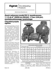
A Válvula de Dilúvio <strong>Model</strong>o <strong>DV</strong>-5 (descrita<br />
na Ficha Técnica TFP1305) é uma válvula<br />
tipo diafragma que depende da pressão da<br />
água<br />
Diaphragm<br />
na Câmara<br />
closed<br />
do Diafragma<br />
against<br />
para<br />
the<br />
manter<br />
water<br />
supply pressure. When the <strong>DV</strong>-5 <strong>Valve</strong><br />
o Diafragma fechado em relação à pressão<br />
is set for service, the Diaphragm<br />
do fornecimento de água. Quando a Válvula<br />
Chamber is pressurized through the<br />
trim<br />
<strong>DV</strong>-5<br />
connections<br />
é regulada<br />
from<br />
para serviço,<br />
the inlet<br />
a<br />
side<br />
Câmara<br />
of<br />
do theDiafragma system’s main é pressurizada control valve, através such das<br />
ligações as an O.S.&Y. de acessórios gateno valve lado or de butterfly aspiração<br />
da valve válvula (Fig. de 1). controlo principal do sistema,<br />
como uma válvula de cunha com fuso ascendente<br />
Openingou ofválvula a pilotde sprinkler, borboleta releases (Fig. 1).<br />
water from the Diaphragm Chamber<br />
A faster abertura than de um it can sprinkler be replenished<br />
piloto causa a<br />
actuação through the de água 1/8 inch da Câmara (3,2 mm) do restrictionmais<br />
provided depressa by do que the o <strong>Model</strong> seu reabaste-<br />
ASV-1<br />
Diafragcimento<br />
Automatic através Shut-Off da restrição <strong>Valve</strong> inde the3,2 diaphragm<br />
fornecida supplypela connection Válvula de (Item Secciona-<br />
5 -<br />
mm<br />
(1/8”)<br />
mento Fig. 2A, Automático also described <strong>Model</strong>o ASV-1 in Technical na ligação<br />
Data de Sheet fornecimento TFP1384). do diafragma This results (Item in a5<br />
- rapid Fig. 2A, pressure também drop descrita in the na Ficha Diaphragm Técnica<br />
TFP1384).<br />
Chamber<br />
Isto<br />
to below<br />
resulta<br />
the<br />
numa<br />
valve<br />
queda<br />
trip<br />
de<br />
point.<br />
pressão<br />
The<br />
rápida<br />
water<br />
na<br />
supply<br />
Câmara<br />
pressure<br />
do Diafragma<br />
then forces<br />
abaixo<br />
the Diaphragm open, permitting water<br />
do ponto de activação da válvula. A pressão<br />
to flow into the system piping, as well<br />
do<br />
as<br />
fornecimento<br />
through the<br />
de<br />
Alarm<br />
água<br />
Port<br />
força<br />
to<br />
a<br />
actuate<br />
abertura<br />
do<br />
the<br />
Diafragma,<br />
system alarms.<br />
permitindo que a água entre<br />
na tubagem do sistema, bem como pela<br />
Passagem As waterpara flows Alarme into para the actuar system, os alarmes<br />
pilot do chamber sistema. of the <strong>Model</strong> ASV-1<br />
the<br />
Automatic Shut-Off <strong>Valve</strong> (Item 5 - Fig.<br />
À 2A) medida becomes que a água pressurized entra no sistema, and thea<br />
câmara ASV-1 piloto automatically da Válvula shuts de Seccionamentphragm<br />
Automático chamber <strong>Model</strong>o supply ASV-1 flow (Item to5 - the Fig.<br />
off the dia-<br />
2A) <strong>DV</strong>-5 fica Diaphragm pressurizada Chamber. e a ASV-1 encerra Shutting automaticamente<br />
off the diaphragm o caudal chamber de fornecimento<br />
supply flow<br />
da prevents câmara the do diafragma <strong>DV</strong>-5 Diaphragm para a Câmara Chamber<br />
from <strong>DV</strong>-5. becoming Encerrar re-pressurized,<br />
o caudal de for-<br />
do<br />
Diafragma<br />
necimento thereby preventing da câmara inadvertent do diafragma closing evita<br />
que of the a Câmara <strong>DV</strong>-5 during do Diafragma a fire (as <strong>DV</strong>-5 may be volte thea<br />
ficar<br />
case<br />
pressurizada,<br />
if an actuation<br />
evitando<br />
device<br />
assim<br />
other<br />
o encerramento<br />
than<br />
a pilot sprinkler<br />
inadvertido<br />
were<br />
da<br />
to<br />
<strong>DV</strong>-5<br />
be closed<br />
durante<br />
after<br />
um<br />
its initial operation, for example a remote<br />
manual control station).<br />
incêndio (que pode acontecer se um dispositivo<br />
de actuação que não um sprinkler<br />
piloto for fechado<br />
WARNING<br />
após o funcionamento<br />
inicial, The <strong>Model</strong> por exemplo, <strong>DV</strong>-5 Supervised um posto de Single controlo Interlockremoto).<br />
<strong>Preaction</strong> <strong>System</strong> <strong>with</strong> Wet Pi-<br />
manual<br />
lot Actuation Trim AVISO described herein<br />
must be installed and maintained in<br />
O<br />
compliance<br />
Sistema de Pré-acção<br />
<strong>with</strong> this<br />
de<br />
document,<br />
Interbloqueio<br />
as<br />
Simples well asSupervisionado <strong>with</strong> the applicable <strong>Model</strong>o standards<br />
<strong>DV</strong>-5 com<br />
Acessórios of the National de Actuação <strong>Fire</strong> Protection Piloto Hidráulica Association,<br />
descrito in addition tem de ser to instalado the standards e manti-<br />
of<br />
aqui<br />
do any em other conformidade authorities com having este documento, jurisdiction.<br />
como Failure com to donormas so mayaplicáveis impair the da<br />
bem<br />
NFPA, performance para além of das the normas related de devices.<br />
quaisquer<br />
outras autoridades competentes. O incumprimento<br />
das normas pode pôr em causa<br />
The owner is responsible for maintaining<br />
their fire protection system and devices<br />
o funcionamento<br />
in proper<br />
dos<br />
operating<br />
dispositivos<br />
condition.<br />
relacionados.<br />
The installing contractor or manufacturer<br />
proprietário should é beresponsável contactedpela <strong>with</strong>manu-<br />
any<br />
O<br />
tenção questions. do seu sistema e dispositivos de<br />
protecção contra incêndios em condições<br />
adequadas de funcionamento. A empresa<br />
de instalação ou o fabricante devem ser contactados<br />
em caso de dúvidas.<br />
Dados Técnicos<br />
Technical<br />
Data<br />
Homologações<br />
Listado por UL e C-UL.<br />
Válvula de Dilúvio<br />
<strong>Model</strong>o Approvals <strong>DV</strong>-5.<br />
UL and C-UL Listed.<br />
Válvula de Retenção para Coluna<br />
<strong>Deluge</strong> <strong>Valve</strong><br />
<strong>Model</strong>o CV-1FR. <strong>DV</strong>-5.<br />
NOTA<br />
Riser Check <strong>Valve</strong><br />
Os<br />
<strong>Model</strong><br />
tubos<br />
CV-1FR.<br />
de extensão DN40 (1-1/2”) utilizam<br />
uma Válvula de Retenção para Coluna DN50<br />
(2”) em conjunto com NOTE a Válvula de Dilúvio<br />
DN40 1-1/2(1-1/2”) inch (DN40) <strong>Model</strong>o risers <strong>DV</strong>-5. utilize a 2 Inch<br />
(DN50) Riser Check <strong>Valve</strong> in combination<br />
<strong>with</strong> the 1-1/2 inch (DN40) <strong>Model</strong><br />
Acessórios <strong>DV</strong>-5 <strong>Deluge</strong> auxiliares <strong>Valve</strong>. da válvula<br />
O Sistema de Pré-acção de Interbloqueio<br />
Simples <strong>Valve</strong> Trim Supervisionado com Acessórios<br />
de The Actuação Supervised Piloto Single Hidráulica Interlock (Fig. 2A/2B) <strong>Preaction</strong>uma<br />
<strong>System</strong> parte With das Wet listagens Pilot Actuation e homolo-<br />
forma<br />
gações Trim (Fig. laboratoriais. 2A/2B) forms Os acessórios a part são of the necessários<br />
laboratory para listings o funcionamento and approvals. correcto The da<br />
válvula trim is<strong>DV</strong>-5.<br />
necessary for proper operation<br />
of the <strong>DV</strong>-5 <strong>Valve</strong>.<br />
Cada conjunto de acessórios inclui os seguintes<br />
Each package itens: of trim includes the following<br />
items:<br />
• Manómetro do Fornecimento de Água<br />
• Water Manómetro Supply da Pressure Câmara do Gauge Diafragma<br />
Diaphragm Chamber<br />
• Ligações da Câmara do Diafragma<br />
Pressure Gauge<br />
•<br />
Diaphragm<br />
Posto de Controlo<br />
Chamber<br />
Manual<br />
Connections<br />
• Manual Válvula de Control Drenagem Station Principal<br />
• Main Válvula Drain de Drenagem <strong>Valve</strong> do Sistema<br />
• <strong>System</strong> Válvula de Drain Teste <strong>Valve</strong> de Alarme<br />
• Alarm Válvula Test de Drenagem <strong>Valve</strong> Automática<br />
• Automatic Manómetro Drain de Ar <strong>Valve</strong> do Sistema<br />
• <strong>System</strong> Ligações Air de Pressure Fornecimento Gauge de Ar<br />
• Air Pressóstato Supply Connections<br />
de Baixa Pressão de Ar de<br />
• Low Supervisão Air Pressure Supervisory<br />
•<br />
Switch<br />
Pressóstato de Alarme de Débito<br />
• Waterflow Pressure Alarm Switch<br />
Para a montagem fácil da combinação dos<br />
acessórios<br />
To ease field<br />
no local,<br />
assembly<br />
os acessórios<br />
of the<br />
são<br />
trim<br />
fornecidorangement,<br />
parcialmente the trim montados, components como mos-<br />
are<br />
artrado<br />
provided na Figura partially 2B. assembled as<br />
A shown combinação Figure dos 2B. acessórios é fornecida<br />
com Theuniões trim arrangement roscadas e juntas is provided galvanizadas <strong>with</strong><br />
ou galvanized pretas. Os acessórios or black galvanizados nipples anddesti-<br />
nam-se tings. The a condições galvanized corrosivas trim isou intended não cor-<br />
fitrosivas,<br />
for non-corrosive e os acessórios orpretos corrosive destinam-se conditions,<br />
whereasà the utilização black trim com issistemas<br />
princi-<br />
principalmente<br />
AFFF. pally intended for use <strong>with</strong> AFFF systems.<br />
NOTA<br />
Quando a pressão do NOTE sistema for superior a<br />
12,1 When bar the (175 system psi), devem pressure ser tomadas is greater providências<br />
than 175para psi (12,1 substituir bar), os provision Manómetros is to<br />
de beÁgua made de toencomenda replace the padrão standard de 20,7 order bar<br />
(300 psi), psi mostrados (20,7 bar) na Water Figura 2A/2B, Pressure por<br />
Manómetros Gauges, shown de Água in de Figure 41,4 bar 2A/2B (600 <strong>with</strong> psi),<br />
encomendados separately ordered em separado. 600 psi (41,4 bar)<br />
Water Pressure Gauges.<br />
Detection <strong>System</strong><br />
In order for a single interlock preaction<br />
Page 9 of 16<br />
Sistema de Detecção<br />
Para que um sistema de pré-acção de interbloqueio<br />
system to<br />
simples<br />
be hydraulically<br />
seja calculado<br />
calculated<br />
hidraulicamente<br />
as a wet pipe como system, um sistema as opposed de tubagem to a<br />
húmida dry pipe (hidráulica), sprinklerpor system, oposição thea detection<br />
system de sprinklers mustde betubagem designed seca to (pneu-<br />
oper-<br />
um sistemmática)ate<br />
sooner o sistema than thedetecção automatic tem sprinklers<br />
on the para sprinkler funcionar piping. mais cedo In the do<br />
de ser<br />
projectado<br />
que caseos of sprinklers wet pilotautomáticos actuation, the na tubagem system<br />
designer sprinklers. selects No caso pilot de sprinklers actuação piloto that<br />
hidráulica, will operate o projectista sooner than do the sistema automatic selecciona<br />
sprinklers sprinklers chosen piloto for que use on vão the funcionar sprinkler<br />
piping. cedo do que os sprinklers automáti-<br />
mais<br />
cos Theescolhidos Supervised para Single utilização Interlock na tubagem <strong>Preaction</strong><br />
sprinklers. <strong>System</strong> With Wet Pilot Actuation<br />
de<br />
O<br />
Trim<br />
Sistema<br />
provides<br />
de Pré-acção<br />
for connection<br />
de Interbloqueio<br />
of a detection<br />
Simples Supervisionado<br />
system consisting<br />
com Acessórios<br />
of wet pilot<br />
de<br />
line sprinklers (heat detectors) and<br />
Actuação Piloto Hidráulica fornece uma ligação<br />
manual control stations interconnected<br />
ao<br />
<strong>with</strong><br />
sistema<br />
minimum<br />
de detecção,<br />
1/2 inch<br />
que<br />
(DN15)<br />
consiste<br />
em<br />
Schedule<br />
sprinklers<br />
40<br />
de<br />
steel<br />
tubagem<br />
pipe.<br />
piloto<br />
The pilot<br />
hidráulica<br />
line<br />
(detectores is connected de calor) to the e “Wet postos Pilot de controlo Detection”<br />
connection interligados shown com, no inmínimo, Figuretuba-<br />
2B.<br />
manual<br />
gem Nominal em aço installation DN15 (1/2”) dimensions especificação for the 40.<br />
A Supervised tubagem piloto Single é ligada Interlock à ligação <strong>Preaction</strong> de “Detecção<br />
<strong>System</strong>Piloto WithHidráulica”, Wet Pilotmostrada Actuation na Trim Figura<br />
are 2B. shown As dimensões in Figure nominais 3. de instalação<br />
do Sistema de Pré-acção de Interbloqueio<br />
Wet pilot sprinklers are to be minimum<br />
Simples Supervisionado com Acessórios de<br />
5.6 K-factor orifice listed or approved<br />
Actuação<br />
automatic<br />
Piloto<br />
sprinklers.<br />
Hidráulica<br />
Manual<br />
são mostradas<br />
Control<br />
na Stations Figura 3. are to be the <strong>Model</strong> MC-1<br />
Os described sprinklers in piloto Technical hidráulicos Data têm Sheet de ser,<br />
no TFP1382. mínimo, listados com orifício factor K<br />
80 Theou maximum sprinklers height automáticos of a wetaprovados.<br />
pilot line<br />
Os above Postos thede <strong>DV</strong>-5 Controlo <strong>Valve</strong>Manual must not têm exceed de ser<br />
do the<strong>Model</strong>o limitations MC-1, shown descrito inna Table Ficha ATécnica<br />
as a<br />
TFP1382. function of the minimum water supply<br />
pressure to the <strong>DV</strong>-5 <strong>Valve</strong> for an<br />
A equivalent altura máxima length da tubagem (pipe plus piloto fittings) hidráulica<br />
the acima pilot line da Válvula up to 500 <strong>DV</strong>-5 feet não todeve the most exce-<br />
of<br />
der remote os limites pilot mostrados sprinkler. na Tabela A como<br />
uma função da pressão de fornecimento<br />
de<br />
Provision<br />
água mínima<br />
must<br />
da<br />
be<br />
Válvula<br />
made for<br />
<strong>DV</strong>-5<br />
installing<br />
para um<br />
comprimento<br />
a 5.6 K-factor<br />
equivalente<br />
orifice, Inspector’s<br />
(tubagem<br />
Test<br />
mais<br />
Connection at the most hydraulically<br />
juntas) da tubagem piloto até 500 ft até ao<br />
demanding location of a wet pilot line<br />
sprinkler<br />
(usually<br />
piloto<br />
adjacent<br />
mais distante.<br />
to the highest and<br />
Devem most remote ser tomadas wet pilot providências line sprinkler para instalar<br />
manual um orifício controlK station). 80, Ligação de Teste de<br />
or<br />
Inspecção na localização mais exigente<br />
hidraulicamente de NOTES uma tubagem piloto<br />
hidráulica<br />
Wet Pilot<br />
(normalmente<br />
Lines must be maintained<br />
adjacente aos<br />
at<br />
sprinklers<br />
a minimum<br />
de<br />
temperature<br />
tubagem piloto<br />
of 40°F/4°C.<br />
hidráulica<br />
mais At a elevado minimum, e distante it recommended ou posto controlo<br />
internally manual). galvanized pipe and cast<br />
that<br />
iron fittings be used for wet pilot lines.<br />
NOTAS<br />
As<br />
<strong>System</strong><br />
Tubagens<br />
Air<br />
Piloto<br />
Pressure<br />
Hidráulicas<br />
Requirements<br />
devem ser<br />
The supervisory air (nitrogen) pressure<br />
is to be 10 plus or minus 2 psi<br />
mantidas à temperatura mínima de 4°C<br />
(40°F).<br />
(0,69 plus or minus 0,07 bar). The use<br />
No of mínimo, a higher recomenda-se supervisoryque pressure a tubagem is<br />
galvanizada subject to approval internamente by the e as Authority<br />
juntas de<br />
ferro Having fundido Jurisdiction, sejam utilizadas and item should tubagens be<br />
piloto understood hidráulicas. that the use of a higher<br />
supervisory pressure may increase<br />
Requisitos water delivery Pressão time. The de Ar use do of Sistema a lower<br />
A supervisory pressão de ar pressure (nitrogénio) may de supervisão prevent<br />
deve<br />
clearing<br />
ser de<br />
the<br />
0,69<br />
alarm<br />
mais<br />
of<br />
ou<br />
the<br />
menos<br />
Supervisory<br />
0,07 bar<br />
Low Pressure Alarm Switch (Item P3 -<br />
Fig. 2A), which is factory set to alarm
Página 10 de 16<br />
Page 10 of 16<br />
TFP1410_PT<br />
TFP1410<br />
Pressão Supply de<br />
Altura Maximum Máxima Pilot do Height, Piloto, (2)<br />
(2)<br />
Fornecimento,<br />
Pressure,<br />
(1)<br />
Feet metros (Meters) (ft)<br />
(1)<br />
PSI<br />
1-1/2" DN40<br />
2" DN50<br />
3" DN80<br />
DN100 4" DN150 6"<br />
DN200 8"<br />
bar (Bar) ( psi) (DN40) (1-1/2”) (DN50) (2”) (DN80) (3”) (DN100) (4”)<br />
(DN150) (6”)<br />
(DN200) (8”)<br />
1,4 20 (20) 71,4 (7) 30,9 (3) 1,4 7 (7) 5,2 17(17) 5,5 18(18) 2,79<br />
(9)<br />
(1,4) (1,4) (0,9) (1,4) (5,2) (5,5)<br />
(2,7)<br />
2,8<br />
40<br />
(40)<br />
24<br />
7,3 (24)<br />
19<br />
5,8 (19) 9,1<br />
30<br />
(30) 11,9<br />
39<br />
(39) 11,6<br />
38<br />
(38) 11,6<br />
38<br />
(38)<br />
(2,8) (7,3) (5,8) (9,1) (11,9) (11,6)<br />
(11,6)<br />
4,1<br />
60<br />
(60)<br />
46<br />
14 (46) 11,6<br />
38<br />
(38) 15,8<br />
52<br />
(52) 16,5<br />
54<br />
(54) 17,1<br />
56<br />
(56) 13,4<br />
44<br />
(44)<br />
(4,1) (14,0) (11,6) (15,8) (16,5) (17,1)<br />
(13,4)<br />
5,5<br />
80<br />
(80)<br />
58<br />
17,8 (58) 16,5<br />
54<br />
(54) 21,3<br />
70<br />
(70) 18,3<br />
60<br />
(60) 21,3<br />
70<br />
(70) 17,8<br />
58<br />
(58)<br />
(5,5) (17,8) (16,5) (21,3) (18,3) (21,3)<br />
(17,8)<br />
6,9<br />
100<br />
(100)<br />
78<br />
23,8 (78) 23,8<br />
78<br />
(78) 28,3<br />
93<br />
(93) 23,8<br />
78<br />
(78) 30,2<br />
99<br />
(99) 19,8<br />
65<br />
(65)<br />
(6,9) (23,8) (23,8) (28,3) (23,8) (30,2)<br />
(19,8)<br />
8,3<br />
120<br />
(120)<br />
87<br />
26,5 (87) 26,5<br />
87<br />
(87) 35,7<br />
117<br />
(117) 35,1<br />
115<br />
(115) 39,6<br />
130<br />
(130) 29,3<br />
96<br />
(96)<br />
(8,3) (26,5) (26,5) (35,7) (35,10 (39,6)<br />
(29,3)<br />
9,7<br />
140<br />
(140)<br />
105<br />
32 (105) 32,6<br />
107<br />
(107) 42,4<br />
139<br />
(139) 43,3<br />
142<br />
(142) 46,9<br />
154<br />
(154) 43<br />
141<br />
(141)<br />
(9,7) (32,0) (32,6) (42,4) (43,3) (46,9)<br />
(43,0)<br />
160<br />
127 123<br />
161<br />
176 161<br />
170<br />
11 (160) 38,7 (127) 37,5 (123) 49,1 (161) 53,6 (176) 49,1 (161) 51,8 (170)<br />
(11,0) (38,7) (37,5) (49,1) (53,6) (49,1)<br />
(51,8)<br />
175<br />
134 138<br />
172<br />
171 194<br />
194<br />
12,1 (175) 40,8 (134) 42,1 (138) 52,4 (172) 52,1 (171) 59,1 (194) 50,1 (194)<br />
(12,1) (40,8) (42,1) (52,4) (52,1) (59,1)<br />
(50,1)<br />
200<br />
160 160<br />
206<br />
223 216<br />
206<br />
13,8 (200) 48,8 (160) 48,8 (160) 62,8 (206) 68 (223) 65,8 (216) 62,8 (206)<br />
(13,8) (48,8) (48,8) (62,8) (68,0) (65,8)<br />
(62,8)<br />
225<br />
185 166<br />
237<br />
233 246<br />
250<br />
15,5 (225) 56,4 (185) 50,6 (166) 72,2 (237) 71 (233) 75 (246) 76,2 (250)<br />
(15,5) (56,4) (50,6) (72,2) (71,0) (75,0)<br />
(76,2)<br />
250<br />
201 199<br />
251<br />
247 275<br />
257<br />
17,2 (250) 61,3 (201) 60,7 (199) 76,5 (251) 75,3 (247) 83,8 (275) 78,3 (257)<br />
(17,2) (61,3) (60,7) (76,5) (75,3) (83,8)<br />
(78,3)<br />
(1)<br />
(1) If supply pressure is variable, assume minimum expected value.<br />
Se a pressão de fornecimento for variável, presuma o valor mínimo esperado.<br />
(2) (2)<br />
Altura Maximum máxima pilot do height piloto for para upaté to 500 150 metros feet (150 (500 meters) ft) de comprimento of equivalent equivalente de tubagem piloto (tubagem mais juntas).<br />
(3)<br />
Interpolação length of pilot entre line pontos (pipe plus de dados fittings). é permitida.<br />
(3)<br />
Interpolation between data points is permitted.<br />
TABELA TABLE A<br />
1-1/2 VÁLVULA thru 8DILÚVIO INCH (DN40 MODELO thru <strong>DV</strong>-5‐DN40 DN200) MODEL até DN200 <strong>DV</strong>-5 DELUGE (1-1/2 até VALVE 8” )<br />
CRITÉRIOS DE PROJECTO DE PILOTO WET HIDRÁULICO PILOT DESIGN PARA ATÉ CRITERIA 500 ft DE FOR COMPRIMENTO UP EQUIVALENTE DE TUBAGEM<br />
500 FEET OF EQUIVALENT PILOTO LENGTH (TUBAGEM OF MAIS PILOTJUNTAS)<br />
LINE (PIPE PLUS FITTINGS)
TFP1410_PT Página 11 de 16<br />
TFP1410<br />
Page 11 of 16<br />
DÉBITO EM LITROS POR MINUTO (l/min)<br />
(1 gpm = 3,785 l/min)<br />
QUEDA DE PRESSÃO NOMINAL EM LIBRAS QUADRADAS” ( psi)<br />
DN40 (1-1/2”)<br />
DN50 (2”)<br />
DN80 (3”)<br />
DN100 (4”)<br />
DN150 (6”)<br />
DN200 (8”)<br />
QUEDA DE PRESSÃO NOMINAL EM bar<br />
1 psi = 0,06895 bar<br />
DÉBITO EM GALÕES POR MINUTO (gpm)<br />
A perda de carga aproximada, com base na fórmula de Hazen e Williams, e expressada em<br />
The approximate comprimento friction de tubagem loss, equivalente based on the de C=120, Hazené and a seguinte: Williams formula and expressed in equivalent length of pipe <strong>with</strong> C=120, is as<br />
follows:<br />
4,6 m (15 ft) de tubagem DN40 (1-1/2”) esp. 40 para a Combinação de Válvula** de 1-1/2” calculada num débito normal de 379 l/min (100 GPM).<br />
15<br />
8,5<br />
feet<br />
m<br />
of<br />
(28<br />
1-1/2<br />
ft) de<br />
Sch.<br />
tubagem<br />
40 pipe<br />
DN50<br />
for<br />
(2”)<br />
the<br />
esp.<br />
1-1/2<br />
40<br />
inch<br />
para a<br />
<strong>Valve</strong><br />
Combinação<br />
Combination**<br />
de Válvula*<br />
calculated<br />
de 2” calculada<br />
on a typical<br />
num débito<br />
flow rate<br />
normal<br />
of 100<br />
de 662<br />
GPM.<br />
l/min (175 GPM).<br />
28 feet of 2 inch Sch. 40 pipe for the 2 inch <strong>Valve</strong> Combination* calculated on a typical flow rate of 175 GPM.<br />
11,3 m (37 ft) de tubagem DN80 (3”) esp. 40 para a Combinação de Válvula* de 3” calculada num débito normal de 1325 l/min (350 GPM).<br />
37 feet of 3 inch Sch. 40 pipe for the 3 inch <strong>Valve</strong> Combination* calculated on a typical flow rate of 350 GPM.<br />
48<br />
14,6<br />
feet<br />
m<br />
of<br />
(48<br />
4 inch<br />
ft) de<br />
Sch.<br />
tubagem<br />
40 pipe<br />
DN100<br />
for the<br />
(4”)<br />
4<br />
esp.<br />
inch<br />
40<br />
<strong>Valve</strong><br />
para a<br />
Combination*<br />
Combinação de<br />
calculated<br />
Válvula* de<br />
on<br />
4”<br />
a<br />
calculada<br />
typical flow<br />
num<br />
rate<br />
débito<br />
of<br />
normal<br />
600 GPM.<br />
de 2271 l/min (600 GPM).<br />
73<br />
22,3<br />
feet<br />
m<br />
of<br />
(73<br />
6 inch<br />
ft) de<br />
Sch.<br />
tubagem<br />
40 pipe<br />
DN150<br />
for the<br />
(6”)<br />
6<br />
esp.<br />
inch<br />
40<br />
<strong>Valve</strong><br />
para a<br />
Combination*<br />
Combinação de<br />
calculated<br />
Válvula* de<br />
on<br />
6”<br />
a<br />
calculada<br />
typical flow<br />
num<br />
rate<br />
débito<br />
of<br />
normal<br />
1500 GPM.<br />
de 5678 l/min (1500 GPM).<br />
10331,4 feet m of (103 8 inch ft) de Sch. tubagem 30 pipe DN200 for the (8”) 8esp. inch 30 <strong>Valve</strong> para a Combination* Combinação de calculated Válvula* de on 8” acalculada typical flow num rate débito of normal 2500 GPM. de 9463 l/min (2500 GPM).<br />
GRÁFICO A<br />
GRAPH A<br />
COMBINAÇÃO DELUGE AND DE CHECK VÁLVULA VALVE DE DILÚVIO COMBINATION*<br />
E RETENÇÃO*<br />
— — NOMINAL PERDA DE PRESSURE PRESSÃO NOMINAL LOSS VERSUS VS DÉBITO FLOW —<br />
* Válvula de * <strong>Model</strong> Dilúvio <strong>DV</strong>-5 <strong>Model</strong>o <strong>Deluge</strong> <strong>DV</strong>-5 <strong>Valve</strong> combinada combined com <strong>with</strong> Válvula <strong>Model</strong>de CV-1FR Retenção Riser para Check Coluna <strong>Valve</strong> <strong>Model</strong>o CV-1FR<br />
**Válvula **1-1/2 de Dilúvio inch <strong>Model</strong>o <strong>DV</strong>-5 <strong>DV</strong>-5 <strong>Deluge</strong> 1-1/2” <strong>Valve</strong> combinada combined com <strong>with</strong> Válvula 2 inchde <strong>Model</strong> Retenção CV-1FR para Riser Coluna Check <strong>Model</strong>o <strong>Valve</strong> CV-1FR 2”
Página 12 de 16<br />
Page 12 of 16<br />
(10 mais ou menos 2 psi). A utilização de<br />
uma pressão de supervisão mais elevada<br />
está<br />
at 5<br />
sujeita<br />
plus or<br />
a<br />
minus<br />
aprovação<br />
1 psi<br />
das<br />
(0,34<br />
Autoridades<br />
plus or<br />
Competentes,<br />
minus 0,07 bar)<br />
tendo<br />
on<br />
em<br />
decreasing<br />
consideração<br />
pressure.<br />
The supervisory air supply pres-<br />
que<br />
a utilização de uma pressão de supervisão<br />
sure of 10 plus or minus 2 psi (0,69<br />
mais<br />
plus<br />
elevada<br />
or minus<br />
pode<br />
0,07<br />
aumentar<br />
bar) can<br />
o tempo<br />
be provided<br />
by de any água. of A the utilização following de methods. uma pres-<br />
de<br />
entrega<br />
são Refer de supervisão to the applicable mais baixa data pode sheet evitar fora<br />
actuação laboratory do approval alarme do information.<br />
Pressóstato de Alarme<br />
de Baixa Pressão de Supervisão (Item P3<br />
-• Fig. <strong>Model</strong> 2A), que G16AC812 está regulado (self de contained)<br />
fábrica para<br />
disparar Automatic a 0,34 Supervisory mais ou menos Air0,07 Supply bar (5<br />
mais described ou menos in1 psi) Gem ao diminuir Technical a pressão. Data<br />
A pressão Sheet TD126. do fornecimento de ar de supervisão<br />
• A maximum de 0,69 mais 200ou psi menos (13,80,07 bar) bar plant (10<br />
mais airou supply menos in2 combination psi) pode ser <strong>with</strong> fornecida the<br />
por <strong>Model</strong> qualquer AMD-1 um dos Air seguintes Maintenance métodos. Device<br />
described a ficha técnica in Technical aplicável para Data ob-<br />
Consulte<br />
ter Sheet informações TFP1221. de homologações laboratoriais.<br />
• A maximum 3000 psi (206,9 bar)<br />
•<br />
nitrogen<br />
Fornecimento<br />
cylinder<br />
de<br />
in<br />
Ar<br />
combination<br />
de Supervisão<br />
<strong>with</strong><br />
Automático<br />
<strong>Model</strong>o G16AC812 (autocon-<br />
the <strong>Model</strong> AMD-3 Nitrogen Maintenance<br />
Device described in Technicatido)<br />
Data<br />
descrito<br />
Sheet<br />
na<br />
TFP1241.<br />
Ficha Técnica TD126 da<br />
Gem.<br />
• Instalação de fornecimento de ar com<br />
máximo de 13,8 NOTE bar (200 psi) em con-<br />
dewcom point o Dispositivo of the air de or Manuten-<br />
nitrogen<br />
Thejunto<br />
supply<br />
ção de<br />
for<br />
Ar<br />
a<br />
<strong>Model</strong>o<br />
system<br />
AMD-1,<br />
exposed<br />
descrito<br />
to freezing<br />
na<br />
Ficha<br />
conditions<br />
Técnica<br />
must<br />
TFP1221.<br />
be maintained below<br />
the lowest ambient temperature to<br />
which • Um cilindro the system de nitrogénio piping com will máximo be exposed.<br />
de 206,9 Introduction bar (3000 of psi) moisture em conjunto into<br />
thecom system o Dispositivo piping cande create Manutenção ice build de<br />
up Nitrogénio that could <strong>Model</strong>o preventAMD-3, proper descrito operation na<br />
of Ficha the system. Técnica TFP1241.<br />
The Supervisory Low Pressure Alarm<br />
NOTA<br />
Switch (Item P3 - Fig. 2A) is factory set<br />
O atponto 5 plusde or condensação minus 1 psi do (0,34 fornecimento plus de minus ar ou 0,07 nitrogénio bar) de onum decreasing sistema exposto pres-sure.<br />
Thede Pressure congelação Relief deve <strong>Valve</strong> ser mantido (Item<br />
condições<br />
abaixo P4- Fig. da 2A) temperatura is factory ambiente set to fully mais open baixa<br />
a at que 25a plus tubagem or minus do sistema 2 psi vai (1,72 estar plus exposta.<br />
minus A introdução 0,14 bar) de and humidade it begins na to tubagem crack<br />
or<br />
do open sistema at apode pressure criar a acumulação of about 18 de gelo psi<br />
que (1,24 pode bar). evitar o funcionamento correcto<br />
do<br />
Friction<br />
sistema.<br />
Loss<br />
O The Pressóstato nominal de pressure Alarme loss de Baixa versus Pressão flow<br />
de data Supervisão for the <strong>Model</strong> (Item <strong>DV</strong>-5 P3 - Fig. <strong>Deluge</strong> 2A) está <strong>Valve</strong> regulado<br />
plus Riser de fábrica Checknos <strong>Valve</strong> 0,34 is mais provided ou menos in<br />
0,07<br />
Graph<br />
bar<br />
A.<br />
(5 mais ou menos 1 psi) ao diminuir<br />
a pressão. A válvula de alívio de pressão<br />
(Item P4 - Fig. 2A) está regulada de fábrica<br />
para abertura total aos 1,72 mais ou<br />
menos 0,14 bar (25 mais ou menos 2 psi) e<br />
começa a abrir-se a uma pressão de cerca<br />
de 1,24 bar (18 psi).<br />
Perda de Carga<br />
A perda de pressão nominal em relação aos<br />
dados de fluxo da Válvula de Dilúvio <strong>Model</strong>o<br />
<strong>DV</strong>-5 mais a Válvula de Retenção para<br />
Coluna é fornecida no Gráfico A.<br />
Instalação<br />
Installation<br />
NOTAS<br />
Os tubos de extensão NOTES DN40 (1-1/2”) utilizam<br />
uma 1-1/2 Válvula inch (DN40) de Retenção risers para utilize Coluna a 2 DN50 Inch<br />
(2”) (DN50) em conjunto Riser Check com a <strong>Valve</strong> Válvula in combination<br />
(1-1/2”) <strong>with</strong> the<strong>Model</strong>o 1-1/2 <strong>DV</strong>-5. inch (DN40) <strong>Model</strong><br />
de Dilúvio<br />
DN40<br />
O<br />
<strong>DV</strong>-5<br />
funcionamento<br />
<strong>Deluge</strong> <strong>Valve</strong>.<br />
correcto da válvula de<br />
Dilúvio Proper<strong>Model</strong>o operation <strong>DV</strong>-5 depende of the <strong>Model</strong> se os respectivos<br />
<strong>Deluge</strong> acessórios <strong>Valve</strong>sestão depends ou não upon instalados their trimde<br />
acordo being com installed as instruções accordance fornecidas <strong>with</strong>nesta<br />
the<br />
<strong>DV</strong>-5<br />
Ficha instructions Técnica. O given incumprimento this Technical<br />
do estipulado<br />
Datano Sheet. diagrama Failure de acessórios to followadequado<br />
the appropriate<br />
causar o trimfuncionamento diagram may incorrecto prevent da<br />
pode<br />
Válvula the <strong>DV</strong>-5 <strong>DV</strong>-5, <strong>Valve</strong> bem from como functioning anular listagens, properly,<br />
as well as e as void garantias listings, do approvals,<br />
fabricante.<br />
homologações<br />
and the manufacturer’s warranties.<br />
A Válvula <strong>DV</strong>-5 tem de ser instalada num local<br />
The <strong>DV</strong>-5 <strong>Valve</strong> must be installed in a<br />
readily<br />
visível<br />
visible<br />
e de fácil<br />
and<br />
acesso.<br />
accessible location.<br />
A The Válvula <strong>DV</strong>-5 <strong>DV</strong>-5, <strong>Valve</strong>, respectivos associated acessórios trim, e and tubagens<br />
wet pilot piloto lines hidráulicas must be devem maintained ser mantidos<br />
minimum à temperatura temperature mínima of de 40°F/4°C.<br />
4°C<br />
at a<br />
(40°F).<br />
Não Heat é permitido tracing ofo aquecimento the <strong>DV</strong>-5 <strong>Valve</strong> da Válvula or its<br />
<strong>DV</strong>-5 associated ou respectivos trim is acessórios. not permitted. O aquecimento<br />
tracing pode cancausar result a formação in the formation de depósitos of<br />
Heat<br />
minerais hardened endurecidos mineral deposits que podem that are causar capable<br />
of preventing incorrecto. proper operation.<br />
funcionamento<br />
A The Válvula <strong>Model</strong> Dilúvio <strong>DV</strong>-5 <strong>Deluge</strong> <strong>Model</strong>o <strong>Valve</strong> <strong>DV</strong>-5 is deve to be ser<br />
instalada<br />
installed<br />
de<br />
in<br />
acordo<br />
accordance<br />
com os<br />
<strong>with</strong><br />
seguintes<br />
the following<br />
criteria:<br />
critérios:<br />
Step 1. All nipples, fittings, and devices<br />
Passo 1.<br />
must<br />
Todas<br />
be<br />
as<br />
clean<br />
uniões<br />
and<br />
roscadas,<br />
free of<br />
juntas<br />
scale<br />
e<br />
dispositivos and burrs before devem installation. estar limpos Use e isentos pipe<br />
de thread oxidação sealant e rebarba sparingly antes on da male instalação. pipe<br />
Utilize threads vedante only. de rosca de tubagem com<br />
moderação e apenas em roscas de tubagem<br />
Stepmacho.<br />
2. The <strong>DV</strong>-5 <strong>Valve</strong> must be<br />
trimmed in accordance <strong>with</strong> Figure<br />
Passo 2A/2B. 2. A Válvula <strong>DV</strong>-5 tem de ser montada<br />
Step<br />
de acordo<br />
3. Care<br />
com<br />
must<br />
a Figura<br />
be taken<br />
2A/2B.<br />
to ensure<br />
Passo that check 3. Deve valves, ser tomado strainers, cuidado globe para<br />
garantir valves, que etc. as are válvulas installed de retenção, <strong>with</strong> thefiltros,<br />
flow<br />
válvulas arrows de in the globo, proper etc., direction. são instaladas com<br />
as Step setas 4. de Drain fluxo tubing na direcção to thecorrecta.<br />
drip funnel<br />
must be installed <strong>with</strong> smooth bends<br />
Passo 4. A tubagem de drenagem para o<br />
that will not restrict flow.<br />
funil de drenagem deve ser instalada com<br />
curvas Step 5. suaves The main para não drain restringir and drip o fluxo. funnel<br />
drain may be interconnected provided<br />
Passo a check 5. O valve dreno isprincipal located e at o least dreno 12 do<br />
funil inches de drenagem (300 mm) below podem the ser drip interligados funnel.<br />
desde que seja colocada uma válvula de retenção<br />
Step<br />
pelo<br />
6. Suitable<br />
menos 300<br />
provision<br />
mm (12”)<br />
must<br />
abaixo<br />
be<br />
do<br />
funil<br />
made<br />
de drenagem.<br />
for disposal of drain water.<br />
Drainage water must be directed such<br />
Passo that it6. will Devem not cause ser tomadas accidental providências damage<br />
a toeliminação property oradequada danger toda persons. água de<br />
para<br />
drenagem. Step 7. A Connect água de drenagem the Diaphragm deve ser<br />
conduzida Chamber de Supply forma Control a não <strong>Valve</strong> causar todanos<br />
the<br />
acidentais inlet sidea of bens theou system’s pessoas. main control<br />
valve in order to facilitate setting of the<br />
Passo 7. Ligue a Válvula de Controlo de<br />
<strong>DV</strong>-5 <strong>Valve</strong> (Fig. 3).<br />
Fornecimento da Câmara do Diafragma ao<br />
lado Stepde 8. aspiração An Inspector’s da válvula Test de Connection,<br />
asdo described sistema para in facilitar the Technical a regula-<br />
controlo<br />
principal<br />
ção Data da section, Válvula <strong>DV</strong>-5 must (Fig. be 3). provided for Wet<br />
Pilot Actuation systems.<br />
TFP1410_PT<br />
TFP1410<br />
Passo 8. Uma Ligação de Teste de Inspecção,<br />
como descrita na secção Dados Técnicos,<br />
Step<br />
deve<br />
9. Unused<br />
ser fornecida<br />
pressure<br />
para<br />
alarm<br />
sistemas<br />
switch<br />
de<br />
Actuação<br />
connections<br />
Piloto<br />
must<br />
Hidráulica.<br />
be plugged.<br />
Step 10. A suitable automatic supervisory<br />
air<br />
Passo 9. Ligações<br />
(nitrogen)<br />
de<br />
supply,<br />
pressóstato<br />
as described<br />
de alarme<br />
não in the utilizadas Technical devem Data ser Section, ligadas. is to be<br />
Passo installed 10. Um in accordance fornecimento <strong>with</strong> de ar the (nitrogéniocable<br />
de Technical supervisão Data automático Sheet and adequado, set for<br />
appli-<br />
como<br />
10 plus<br />
descrito<br />
or minus<br />
na secção<br />
2 psi<br />
Dados<br />
(0,69<br />
Técnicos,<br />
plus or<br />
minus 0,14 bar).<br />
deve ser instalado de acordo com a Ficha<br />
Step Técnica 11. Aaplicável desiccant e regulado dryer, when para 0,69 required<br />
ou menos for the 0,14 supervisory bar (10 mais air supply, ou menos is<br />
mais<br />
2 topsi).<br />
be installed between a drip leg and<br />
the <strong>Model</strong> AMD-1 Air Maintenance Device<br />
or 11. between Um desumidificador the <strong>Model</strong> G16AC812<br />
por absor-<br />
Passo<br />
ção, Automatic quando Supervisory necessário para Air o Supply fornecimento<br />
the de <strong>Preaction</strong> ar de supervisão, Trim. deve ser instalado<br />
and<br />
entre um tubo de purga e o Dispositivo de<br />
Step 12. The Supervisory Low Pressure<br />
Alarm Switch is to be wired to the<br />
Manutenção de Ar <strong>Model</strong>o AMD-1, ou entre<br />
o<br />
supervisory<br />
Fornecimento<br />
alarm<br />
de Ar<br />
initiating<br />
de Supervisão<br />
circuit<br />
Automático<br />
of<br />
an alarm<br />
<strong>Model</strong>o<br />
panel.<br />
G16AC812 e os Acessórios<br />
de Pré-acção.<br />
Step 13. Conduit and electrical connections<br />
12. O are Pressóstato to be made Alarme in accordance de Baixa<br />
Passo<br />
Pressão <strong>with</strong> thede requirements Supervisão deve of ser authority ligado ao<br />
circuito havingde jurisdiction actuação do and/or alarme thede National supervisão<br />
Electric de um Code. painel de alarme.<br />
Passo Step 13. 14. As Before ligações a system de condutas hydrostatic e electricidade<br />
test is performed devem ser efectuadas in accordance de acordo <strong>with</strong><br />
com NFPA os requisitos 13 systemdas acceptance autoridades test competentequirements,<br />
e/ou leis nacionais. the <strong>DV</strong>-5 Diaphragm<br />
re-<br />
Chamber is to be depressurized; the<br />
Passo Automatic 14. Antes Drain de <strong>Valve</strong> ser efectuado (Item 4, um Fig. teste 2A)<br />
hidrostático is to be temporarily do sistema, replaced de acordo <strong>with</strong>com a 1/2 os<br />
requisitos inch NPTde plug, teste the de conformidade 3/32 inch Vent de Fitting<br />
NFPA (16 - 13, Fig. a 2A) Câmara is todo beDiafragma temporarily <strong>DV</strong>sistema<br />
5 replaced tem de ser <strong>with</strong> despressurizada, a 1/4 inch NPTa plug, Válvula and de<br />
Drenagem the Diaphragm Automática Cover (Item Bolts 4, Fig. must 2A) tem be<br />
de uniformly ser temporariamente and securely substituída tightened por<br />
um using tampão a cross-draw 1/2” NPT, o Elemento sequence. de Purga After<br />
3/32” tightening, (16 - Fig. double-check 2A) tem de ser to temporariamente<br />
make certain<br />
that<br />
substituído<br />
all of the<br />
por um<br />
Diaphragm<br />
tampão 1/4”<br />
Cover<br />
NPT<br />
e<br />
Bolts<br />
os Parafusos<br />
are securely<br />
da Tampa<br />
tightened.<br />
do Diafragma têm<br />
de ser bem apertados uniformemente<br />
em sequência cruzada. Depois de apertar,<br />
verifique novamente para garantir que<br />
todos os Parafusos da Tampa do Diafragma<br />
estão bem apertados.
TFP1410_PT Página 13 de 16<br />
TFP1410<br />
Page 13 of 16<br />
Procedimento<br />
de <strong>Valve</strong> Regulação Setting da<br />
Válvula Procedure<br />
Steps 1 through 12 are to be performed<br />
Os passos<br />
when<br />
de 1<br />
initially<br />
a 2 devem<br />
setting<br />
ser<br />
the<br />
efectuados<br />
<strong>Model</strong><br />
quando <strong>DV</strong>-5 <strong>Deluge</strong> regular <strong>Valve</strong>; inicialmente after a an Válvula operational<br />
test <strong>Model</strong>o of the<strong>DV</strong>-5, fire protection após um teste system; ope-<br />
de<br />
Dilúvio<br />
racional or, afterao system sistema operation de protecção due to acontra<br />
fire.<br />
incêndios ou após a operação do sistema<br />
devido Step 1. a um Close incêndio. the Main Control <strong>Valve</strong>.<br />
Step 2. Close the Diaphragm Chamber<br />
Supply Control <strong>Valve</strong> and the Su-<br />
Passo 1. Feche a Válvula de Controlo Principalpervisory<br />
Air Supply Control <strong>Valve</strong>.<br />
Passo Step 2. 3. Feche Open a the Válvula Mainde Drain Controlo <strong>Valve</strong>, de<br />
Fornecimento <strong>System</strong> Drainda <strong>Valve</strong>, Câmara and do Diafragma all auxiliary e a<br />
Válvula drainsde inControlo the system. de Fornecimento After water de Ar<br />
de ceases Supervisão. to discharge, close the <strong>System</strong><br />
Drain <strong>Valve</strong> and auxiliary drain valves.<br />
Passo 3. Abra a Válvula de Drenagem Principal,<br />
a Válvula de Drenagem do Sistema<br />
Leave the Main Drain <strong>Valve</strong> open.<br />
e Step todos 4. os Depress drenos auxiliares the plunger do sistema. of the<br />
Quando Automatic terminar Draina descarga <strong>Valve</strong> to de verify água, that feche it<br />
a isVálvula opende and Drenagem that the do <strong>DV</strong>-5 Sistema <strong>Valve</strong> e as válvulas<br />
completely de drenagem drained. auxiliares. Deixe a Vál-<br />
is<br />
vula Stepde 5. Drenagem Clean thePrincipal Strainer aberta. in the Diaphragm<br />
Passo 4. Pressione<br />
Chamber<br />
o êmbolo<br />
Supply<br />
da<br />
connection<br />
Válvula de<br />
by removing the clean-out plug and<br />
Drenagem<br />
strainer basket.<br />
Automática<br />
The<br />
para<br />
Strainer<br />
confirmar<br />
may<br />
que<br />
be<br />
está<br />
flushed<br />
aberta<br />
out<br />
e que<br />
by<br />
a<br />
momentarily<br />
Válvula <strong>DV</strong>-5 está<br />
opening<br />
completamente<br />
the Diaphragm drenada. Chamber Supply Control<br />
<strong>Valve</strong>. 5. Limpe o Filtro da ligação do For-<br />
Passo<br />
necimento Step 6. Reset da Câmara the actuation do Diafragma, system. removendo<br />
o tampão de limpeza e o cesto do<br />
filtro.<br />
Manual<br />
O Filtro<br />
Actuation<br />
pode ser<br />
—<br />
exposto<br />
Push the<br />
momentaneamente,<br />
abrindo a Válvula de Controlo<br />
operating<br />
lever up; however, do not close the<br />
hinged cover at this time.<br />
de Fornecimento da Câmara do Diafragma.<br />
Wet Pilot Actuation — Replace operated<br />
pilot 6. Regule sprinklers novamente and/or o sistema reset the de<br />
Passo<br />
actuação. manual control stations.<br />
Actuação Manual — Empurre a alavanca de<br />
operação para cima,<br />
NOTE<br />
mas não feche a tampa<br />
In order to prevent the possibility of a<br />
articulada nesta altura.<br />
subsequent operation of an overheated<br />
solder Piloto type Hidráulica pilot sprinkler, — Substitua any<br />
Actuação<br />
sprinklers solder type piloto pilot utilizados sprinklers e/ou that regule were novamente<br />
possiblyos exposed postos de controlo to a temperature<br />
manual.<br />
greater than their maximum rated ambient<br />
must be replaced. NOTA<br />
Para<br />
Step<br />
evitar<br />
7. Open<br />
a possibilidade<br />
the Diaphragm<br />
de uma<br />
Chamber<br />
operação<br />
subsequente Supply Control de um <strong>Valve</strong> sprinkler and allow piloto time tipo for solda<br />
fullsobreaquecido, pressure to build quaisquer up in sprinklers the Diaphragm<br />
tipo solda Chamber. que tenham sido expostos a<br />
piloto<br />
uma temperatura superior ao seu ambiente<br />
máximo Step 8. recomendado Operate (open) devem the ser substituídos.<br />
Manual<br />
Control Station to vent trapped air from<br />
the Diaphragm Chamber. If necessary,<br />
Passo first open 7. Abra the a hinged Válvula cover, de Controlo and then de<br />
Fornecimento fully pull down da on Câmara the operating do Diafragma lever. e<br />
aguarde SLOWLY algum closetempo the operating para que lever, a pressão by<br />
total pushing se acumule it up, na after Câmara aerated do Diafragma. water<br />
ceases to discharge from the Manual<br />
Passo Control 8. Station Opere (abra) drain o tubing. Posto de Close Controlo the<br />
Manual hingedpara cover purgar and ar insert preso ana new Câmara break do<br />
Diafragma. rod in the small Se necessário, hole through abra the primeiro top ofa<br />
tampa the enclosing articulada box. e depois puxe completamente<br />
Crack<br />
para<br />
open<br />
baixo<br />
the Inspector’s<br />
a alavanca de<br />
Test<br />
operação.<br />
Connection<br />
LENTAMENTE and any other a alavanca vent valves de opera-<br />
Feche on<br />
ção, empurrando-a para cima após o término<br />
da descarga da água arejada da tubagem<br />
the wet<br />
de<br />
pilot<br />
drenagem<br />
line to<br />
do<br />
relieve<br />
Posto<br />
trapped<br />
de Controlo<br />
air.<br />
Manual.<br />
After the<br />
Feche<br />
discharge<br />
a tampa<br />
of<br />
articulada<br />
air has stopped,<br />
e insira<br />
close the vent valves and the Inspector’s<br />
Test Connection.<br />
uma nova vareta para quebra de vidro no<br />
pequeno orifício através do topo da caixa<br />
da Step estrutura. 9. Inspect the drain connection<br />
from the Manual Control Station. Any<br />
Abra leaksa must Ligação bede corrected Teste de before Inspecção pro-ceeding<br />
to outras the next válvulas step. de ventilação da<br />
quaisquer<br />
tubagem piloto hidráulica para libertar ar<br />
preso.<br />
Step 10. Verify the ability for the <strong>DV</strong>-5<br />
Diaphragm to hold pressure as follows:<br />
o término da descarga de ar, feche as<br />
Após<br />
válvulas With thede diaphragm ventilação e chamber a Ligação pressurized<br />
Inspecção. per Step 8, temporarily close the<br />
de Teste<br />
de<br />
Passo Diaphragm 9. Inspeccione Chamber a ligação Supplyde Control drenagem<br />
<strong>Valve</strong>,<br />
do Posto<br />
and monitor<br />
de Controlo<br />
the<br />
Manual.<br />
Diaphragm<br />
Quaisquer<br />
Chamber<br />
fugas<br />
Pressure<br />
devem ser<br />
Gauge<br />
corrigidas<br />
for a<br />
antes<br />
drop in<br />
de<br />
pressure.<br />
prosseguir para o próximo passo.<br />
If a drop in pressure is noted, the <strong>DV</strong>-5<br />
Passo Diaphragm 10. Verifique is to be a capacidade replaced and/or de manutenção<br />
any leaks da must pressão bedo corrected Diafragma before <strong>DV</strong>-5,<br />
como proceeding se segue: to the next step.<br />
Com If thea câmara Diaphragm do diafragma Chamber pressurizada Pressure<br />
segundo Gauge o does Passo not 8, feche indicate temporariamente a drop in<br />
a pressure, Válvula de Controlo re-opende the Fornecimento Diaphragmda<br />
Câmara Chamber do Diafragma Supply Control e monitorize <strong>Valve</strong>o and Manómetro<br />
proceedda toCâmara the next do step. Diafragma em relação<br />
Step a quedas 11. Replace de pressão. operated automatic<br />
Se sprinklers for observada on the uma system queda de piping pressão, ando<br />
Diafragma then open<strong>DV</strong>-5 the deve Supervisory ser substituído Air Supply e/ou<br />
quaisquer<br />
Control <strong>Valve</strong><br />
fugas<br />
and<br />
corrigidas<br />
allow<br />
antes<br />
the system<br />
de prosseguir<br />
to<br />
automatically<br />
para o próximo<br />
re-establish<br />
passo.<br />
its nominal<br />
air pressure of 10 psi (0,69 bar). Observe<br />
o Manómetro the Automatic da Câmara Drain do <strong>Valve</strong> Diafragma for<br />
Se<br />
não leaks. indicar If uma there queda are de pressão, leaks, abra determine/correct<br />
a Válvula the de cause Controlo of thede leakage Forneci-<br />
novamentmento<br />
problem da Câmara <strong>with</strong>in the do Riser Diafragma Check e prossiga <strong>Valve</strong>.<br />
para o passo seguinte.<br />
NOTE<br />
Passo In order 11. Substitua to prevent sprinklers the possibility automáticos of a<br />
utilizados subsequent na tubagem operation do sistema of ane depois overheated<br />
a Válvula solder Controlo type automatic de Fornecimento sprin-<br />
abra<br />
de kler, Ar de anySupervisão solder type e permita automatic que o sprinklers<br />
restabeleça that were a sua possibly pressão exposed nominal de to ar a<br />
sistema<br />
de temperature 0,69 bar (10 psi). greater Verifique thanse their a Válvula maximum<br />
ratedAutomática ambient must apresenta be replaced. fugas. Se<br />
de<br />
Drenagem<br />
existirem Step 12. fugas, Slowlydetermine/corrija open the Main Control a causa<br />
do <strong>Valve</strong>. problema Closedas thefugas Mainna Drain Válvula <strong>Valve</strong> de Retenção<br />
soon para as water Coluna. discharges from the<br />
as<br />
drain connection. Observe the Automatic<br />
Drain <strong>Valve</strong><br />
NOTA<br />
for leaks. If there are<br />
Para leaks, evitar determine/correct a possibilidade de the uma cause operação of<br />
subsequente the leakagede problem. um sprinkler If there automático are no<br />
tipo leaks, solda the sobreaquecido, <strong>DV</strong>-5 <strong>Valve</strong> quaisquer ready sprinklers<br />
placed automáticos in service tipo and solda theque Main tenham Control sido<br />
to be<br />
expostos <strong>Valve</strong> must a uma then temperatura be fully opened. superior ao seu<br />
ambiente máximo recomendado devem ser<br />
substituídos. NOTES<br />
When the Main Control <strong>Valve</strong> is<br />
Passo opened, 12. Abra the pressure lentamente ona Válvula the Diaphragm<br />
Principal. Chamber Feche maya increase. Válvula de This Dre-<br />
de<br />
Controlo<br />
nagem increase Principal pressure logo após is normal, a descarga and da if<br />
água the da pressure ligação de is greater drenagem. than Verifique 250 psi se<br />
a (17,2 Válvula bar), de Drenagem the pressure Automática is beapre-<br />
lievedfugas. by Se partially existirem andfugas, temporarily determisentne/corrija<br />
opening a the causa Manual do problema Controldas Station; fugas.<br />
Se however, não existirem do not fugas, allowa Válvula the pressure <strong>DV</strong>-5 está as<br />
indicated on the Diaphragm Chamber<br />
pronta a ser posta em serviço e a Válvula de<br />
Controlo Principal tem então de ser totalmente<br />
Pressure<br />
aberta.<br />
Gauge to drop below the<br />
supply pressure shown on the Water<br />
Supply PressureNOTAS<br />
Gauge, since this action<br />
may a Válvula result inde tripping Controlo of Principal the <strong>DV</strong>-5é<br />
aberta, <strong>Valve</strong>. a pressão na Câmara do Diafragma<br />
Quando<br />
pode Afteraumentar. setting aEste fireaumento protection de pressão system, é<br />
normal, notify e the se a proper pressão authorities for superior a and 17,2 advisepsi),<br />
those a pressão responsible deve ser libertada for monitoring abrin-<br />
bar<br />
(250<br />
do proprietary parcial e temporariamente and/or central o Posto station de<br />
Controlo alarms. Manual; no entanto, não permita<br />
que a pressão indicada no Manómetro da<br />
Câmara do Diafragma desça abaixo da pressão<br />
de fornecimento mostrada no Manómetro<br />
do Fornecimento de Água, dado que isso<br />
pode causar a activação da Válvula <strong>DV</strong>-5.<br />
Depois de instalar um sistema de protecção<br />
contra incêndios, notifique as autoridades<br />
competentes e informe todos os responsáveis<br />
pela monitorização de alarmes privados<br />
e/ou de estações centrais.<br />
Cuidados<br />
Care and<br />
e<br />
Manutenção<br />
Maintenance<br />
Os<br />
The<br />
seguintes<br />
following<br />
procedimentos,<br />
procedures, inspections,<br />
inspecções e<br />
manutenção and maintenance devem must ser efectuados be performed como<br />
indicado, as indicated, para além in addition de quaisquer to anyrequisitos<br />
specific<br />
específicos requirements da NFPA, of the e quaisquer NFPA, and deficiências<br />
impairment devem ser must imediatamente be immediately corrigidas. cor-<br />
any<br />
O<br />
rected.<br />
proprietário é responsável pela inspecção,<br />
Theverificação owner is e responsible manutenção for do the respectivspection,<br />
sistema testing, e dispositivos and maintenance de protecção of<br />
in-<br />
contra their fire incêndios protection em conformidade system and com devices<br />
documento, in compliance bem como <strong>with</strong> com this as normas docu-<br />
este<br />
aplicáveis ment, asda well NFPA as (ex., <strong>with</strong> NFPA the25), applicable para além<br />
das standards normas de of the quaisquer National outras <strong>Fire</strong>autorida-<br />
des tioncompetentes. Association A (e.g., empresa NFPA de instalação 25), ou addition o fabricante to do theproduto standards devem of ser any con-<br />
Protectactados<br />
authority<br />
em<br />
having<br />
caso de<br />
jurisdiction.<br />
dúvidas.<br />
The installing<br />
contractor or product manufacturer<br />
should que be contacted os sistemas relative de sprink-<br />
to<br />
Recomenda-se<br />
lers any automáticos questions. sejam inspeccionados,<br />
testados It is recommended e mantidos por that um automatic<br />
Serviço de<br />
Inspecção sprinklerqualificado, systemsde beacordo inspected, com os<br />
requisitos tested, and locais maintained e/ou leis nacionais. by a qualified<br />
Inspection Service<br />
NOTAS<br />
in accordance <strong>with</strong><br />
local requirements and/or national<br />
Alguns code. dos procedimentos realçados nesta<br />
secção causam o funcionamento dos alarmes<br />
associados. Consequentemente, NOTES<br />
deve<br />
ser Some dada of notificação the procedures ao proprietário outlined e aos in<br />
bombeiros, this section estação will result central inou operation outra estação<br />
thede associated sinalização alarms. a que estejam Consequently,<br />
ligados os<br />
of<br />
alarmes. notification must first be given to the<br />
owner and the fire department, central<br />
Antes<br />
station,<br />
de fechar<br />
or other<br />
a válvula<br />
signal<br />
de<br />
station<br />
controlo<br />
to which<br />
principal<br />
the alarms de um sistema are connected. de protecção contra<br />
incêndios para efectuar manutenção nesse<br />
sistema, Before deve closing ser primeiro a fire protection obtida autorização<br />
main para control encerrar valve os sistemas for maintenance<br />
de protecção<br />
system<br />
contra work incêndios on the fireafectados protection junto system das autoridades<br />
that<br />
it controls,<br />
competentes,<br />
permission<br />
e todo<br />
to<br />
o<br />
shut<br />
pessoal<br />
down<br />
afectado<br />
the<br />
affected<br />
por esta<br />
fire<br />
acção<br />
protection<br />
deve ser notificado.<br />
systems must<br />
first be obtained from the proper<br />
authorities and all personnel who may
Página 14 de 16<br />
Page 14 of 16<br />
Procedimento de Teste de Funcionamento<br />
Anual<br />
be affected by this action must be notified.<br />
O funcionamento adequado da Válvula<br />
<strong>DV</strong>-5 (por ex., a abertura da Válvula <strong>DV</strong>-5<br />
durante Annualuma Operation situação Test de incêndio) Procedure deve<br />
ser Proper verificado operation pelo menos of the uma <strong>DV</strong>-5 vez por <strong>Valve</strong> ano,<br />
como (i.e., opening se segue: of the <strong>DV</strong>-5 <strong>Valve</strong> as during<br />
a fire condition) must be verified at<br />
Passo 1. Se for necessário impedir o fluxo<br />
least once a year as follows:<br />
de água para além do tubo de extensão,<br />
efectue os passos seguintes.<br />
Step 1. If water must be prevented<br />
from • Feche flowing a Válvula beyond de the Controlo riser, perform Principal.<br />
theAbra following a Válvula steps. de Drenagem Principal.<br />
•<br />
Close<br />
Abra a<br />
the<br />
Válvula<br />
Main<br />
de<br />
Control<br />
Controlo<br />
<strong>Valve</strong>.<br />
Principal,<br />
Open<br />
rodando<br />
uma volta para além da posição<br />
the Main Drain <strong>Valve</strong>.<br />
• Open na qual the a água Maincomeça Control a sair <strong>Valve</strong> da Válvula one<br />
turn de Drenagem beyond the Principal. position at which<br />
water just begins to flow from the<br />
• Main Feche Drain a Válvula <strong>Valve</strong>. de Drenagem Principal.<br />
Passo<br />
• Close<br />
2. Abra<br />
the Main<br />
a Ligação<br />
Drain<br />
de<br />
<strong>Valve</strong>.<br />
Teste de Inspecção<br />
da Tubagem Piloto Hidráulica.<br />
Step 2. Open the Wet Pilot Line Inspector’s<br />
Test Connection.<br />
NOTA<br />
Esteja preparado para efectuar rapidamente<br />
os Passos 3, 4 e 5 se NOTE for necessário impedir o<br />
fluxo<br />
Be prepared<br />
de água para<br />
to quickly<br />
além do<br />
perform<br />
tubo de<br />
Steps<br />
extensão.<br />
3, 4, and 5, if water must be prevented<br />
from flowing beyond the riser.<br />
Passo Step 3. 3. Verifique Verify that se a the Válvula <strong>DV</strong>-5 <strong>DV</strong>-5 <strong>Valve</strong> foi has activada,<br />
tripped, como asindicado indicated pelo by fluxo thede flow água of no<br />
sistema. water into the system.<br />
Passo Step 4. Feche Closea the Válvula system’s de Controlo Main Principatroldo<br />
<strong>Valve</strong>. sistema.<br />
Con-<br />
Passo Step 5. Feche Close a the Válvula Diaphragm de Controlo Chamber<br />
Supply Control da Câmara <strong>Valve</strong> do Diafragma and the Su-<br />
e a<br />
de<br />
Fornecimento<br />
Válvula pervisory de Controlo Air Supply de Fornecimento Control <strong>Valve</strong>. de Ar<br />
de Step Supervisão. 6. Reset the <strong>DV</strong>-5 <strong>Deluge</strong> <strong>Valve</strong><br />
Passo<br />
in accordance<br />
6. Regule novamente<br />
<strong>with</strong> the <strong>Valve</strong><br />
a Válvula<br />
Setting<br />
de Dilúvio<br />
Procedure.<br />
<strong>DV</strong>-5, de acordo com o Procedimento<br />
de<br />
Quarterly<br />
Regulação<br />
Waterflow<br />
da Válvula.<br />
Alarm Test<br />
Procedimento<br />
Procedure<br />
Trimestral de Teste do<br />
Alarme<br />
Testing<br />
de<br />
of<br />
Débito<br />
the system waterflow alarms<br />
must be performed quarterly. To test<br />
A the verificação waterflow dos alarm, alarmes open de débito the Alarm do sistema<br />
Test deve <strong>Valve</strong>, ser which efectuada will allow trimestralmente. a flow of<br />
Para water verificar to the Waterflow o alarme de Pressure débito, Alarm abra a<br />
Válvula Switchde and/or Teste de Water Alarme, Motor que vai Alarm. permitir<br />
um Upon fluxo satisfactory de água no Pressóstato completion de of Alarme the<br />
de test, Débito close e/ou theno Alarme Test de <strong>Valve</strong>. Motor Hidráulico.<br />
Após a conclusão satisfatória do teste,<br />
Quarterly Supervisory Low Pressure<br />
Alarm Test Procedure<br />
feche a Válvula de Teste de Alarme.<br />
Procedimento Proper operation Trimestral of thede Supervisory<br />
Teste do<br />
Alarme Low Pressure de Baixa Alarm Pressão Switch de Supervisão must be<br />
performed quarterly as follows:<br />
O funcionamento adequado do Pressóstato<br />
de Step Alarme 1. Crack de Baixa open Pressão the <strong>System</strong> de Supervisão Main<br />
deve Drainser <strong>Valve</strong> verificado for thetrimestralmente, Riser Check <strong>Valve</strong> como<br />
se (Item segue: P7, Figure 2A) to slowly relieve<br />
supervisory air pressure from the system.<br />
Verify 1. Abra that a Válvula the de Supervisory Drenagem Princi-<br />
Low<br />
Passo<br />
pal Pressure do Sistema Alarm para Switch que a Válvula is operational de Retenção<br />
andpara that Coluna the low (Item pressure P7, Figure set2A) point liberte is<br />
lentamente approximately a pressão 5 psi (0,34 de ar de bar). supervisão<br />
do<br />
Step<br />
sistema.<br />
2. Close<br />
Verifique<br />
the <strong>System</strong><br />
se o Pressóstato<br />
Main Drain<br />
de<br />
Alarme <strong>Valve</strong> (Item de Baixa P7, Pressão Figure de 2A) Supervisão and allow está<br />
operacional the systeme supervisory se o ponto regulado pressure de of baixa 10<br />
plus or minus 2 psi (0,69 plus or minus<br />
pressão está aproximadamente a 0,34 bar<br />
(5 psi).<br />
0,14 bar) to be automatically re-established.<br />
2. The Feche Supervisory a Válvula Low de Drenagem Pressure<br />
Passo<br />
Principal Alarm Switch do Sistema should(Item return P7, toFigura its “normal”<br />
permita condition. que a pressão de supervisão do<br />
2A)<br />
e<br />
sistema Pressure de 0,69 Relief mais <strong>Valve</strong> ou menos Maintenance 0,14 bar (10<br />
mais Overou pressurization menos 2 psi) seja of the automaticamentingrestabelecida.<br />
<strong>with</strong> air will result O Pressóstato in the opening de Alarme of<br />
system pip-<br />
de theBaixa Pressure Pressão Relief de Supervisão <strong>Valve</strong> (Item deve voltar P4,<br />
ao Fig. seu 2A). estado If the “normal”. Relief <strong>Valve</strong> continues<br />
to bleed air after the system pressure<br />
Manutenção has been reduced da válvula to de its alívio normal de supervisory<br />
pressure range of 10 plus or<br />
pressão<br />
A minus sobrepressurização 2 psi (0,69 plus da tubagem or minusdo 0,14 sistema<br />
bar), com mostar likely causa debris a abertura became da lodged válvula<br />
de in alívio the seating de pressão area. (Item To P4, helpFig. clean 2A). Se thea<br />
válvula seatingde area, alívio slowly de pressão pull continuar up thea ring sangrar<br />
at the ar após top of a redução the Relief da <strong>Valve</strong> pressão to do allow sistema<br />
fullpara flowo of intervalo air through de pressão the Relief de supervi-<br />
<strong>Valve</strong>,<br />
a<br />
são andnormal then release de 0,69 mais the ou ringmenos to allow 0,14 the bar<br />
(10 Relief mais <strong>Valve</strong> ou menos to snap 2 psi), closed. é provável Repeat que the se<br />
acumulem cleaning procedure detritos na as área necessary. da sede. Para<br />
ajudar a limpar a área da sede, empurre<br />
lentamente<br />
Limited<br />
para cima o vedante localizado<br />
no topo da válvula de alívio de pressão para<br />
permitir Warranty<br />
o fluxo total de ar através da válvula<br />
de alívio de pressão, e depois liberte o vedante<br />
<strong>Products</strong> para permitir manufactured que a válvula by <strong>Tyco</strong> de alívio <strong>Fire</strong><br />
de <strong>Products</strong> pressão se are feche. warranted Repita o solely procedimento<br />
the<br />
de original limpeza Buyer conforme for necessário. ten (10) years<br />
against defects in material and workmanship<br />
when paid for and properly<br />
installed and maintained under normal<br />
Garantia<br />
use and service. This warranty will expire<br />
ten (10) years from date of shipment<br />
by <strong>Tyco</strong> <strong>Fire</strong> <strong>Products</strong>. No war-<br />
Limitada<br />
ranty is given for products or<br />
Os components produtos fabricados manufactured pela <strong>Tyco</strong> by companies<br />
são notgarantidos affiliated apenas by ownership ao Comprador <strong>with</strong><br />
<strong>Fire</strong> <strong>Products</strong><br />
original <strong>Tyco</strong> <strong>Fire</strong> durante <strong>Products</strong> dez (10) or for anos products contra defeitos<br />
components de fabrico e which de material have quando been subject pagos,<br />
and<br />
correctamente to misuse, improper instalados installation, e mantidos corrosion,<br />
or which normais have de not utilização been installed, e serviço.<br />
em<br />
condições<br />
Esta maintained, garantia modified expira dez or(10) repaired anos após in ac-cordance<br />
de envio <strong>with</strong> pela applicable <strong>Tyco</strong> <strong>Fire</strong> Standards <strong>Products</strong>. Não of<br />
data<br />
é the dada National nenhuma <strong>Fire</strong> garantia Protection para produtos Association,<br />
and/or the fabricados standards por empresas of any other não<br />
ou<br />
componentes<br />
afiliadas Authorities por propriedade Having Jurisdiction. com a <strong>Tyco</strong> Materials<br />
found<br />
<strong>Fire</strong><br />
<strong>Products</strong> ou<br />
by<br />
para<br />
<strong>Tyco</strong><br />
produtos<br />
<strong>Fire</strong> <strong>Products</strong><br />
e componentes<br />
to be<br />
defective<br />
que tenham<br />
shall<br />
sido<br />
be either<br />
sujeitos<br />
repaired<br />
a utilização<br />
or<br />
replaced, at <strong>Tyco</strong> <strong>Fire</strong> <strong>Products</strong>’ sole<br />
incorrecta, instalação incorrecta, corrosão<br />
option. <strong>Tyco</strong> <strong>Fire</strong> <strong>Products</strong> neither assumes,<br />
ou que não<br />
nor<br />
tenham<br />
authorizes<br />
sido instalados,<br />
any person<br />
mantidos,<br />
to<br />
assume<br />
modificados<br />
for it, any<br />
ou<br />
other<br />
reparados<br />
obligation<br />
de acordo<br />
in<br />
com connection as normas <strong>with</strong> aplicáveis the saleda ofNFPA, products e/ou or as<br />
normas parts of de products. outras Autoridades <strong>Tyco</strong> <strong>Fire</strong>Competen-<br />
tes. shall Os not materiais be responsible considerados fordefeituosos<br />
sprinkler<br />
<strong>Products</strong><br />
pela system <strong>Tyco</strong> design <strong>Fire</strong> <strong>Products</strong> errorsserão inaccurate reparados or ou<br />
substituídos, incompleteà information descrição exclusiva supplied da <strong>Tyco</strong> by<br />
<strong>Fire</strong> Buyer <strong>Products</strong>. or Buyer’s A <strong>Tyco</strong> representatives.<br />
<strong>Fire</strong> <strong>Products</strong> não assume,<br />
nem autoriza ninguém a assumir por<br />
IN NO EVENT SHALL TYCO FIRE<br />
si,<br />
PRODUCTS<br />
qualquer obrigação<br />
BE LIABLE,<br />
relativa à<br />
IN<br />
venda<br />
CONde<br />
produtos<br />
TRACT,<br />
ou<br />
TORT,<br />
peças<br />
STRICT<br />
de produtos.<br />
LIABILITY<br />
A <strong>Tyco</strong><br />
OR<br />
<strong>Fire</strong><br />
<strong>Products</strong> UNDERnão ANY será OTHER responsável LEGAL por erros THE- de<br />
projecção ORY, FOR do INCIDENTAL, sistema de sprinklers INDIRECT, ou de<br />
informações SPECIAL imprecisas OR CONSEQUENTIAL<br />
ou incorrectas fornecidas<br />
DAMAGES, pelo Comprador INCLUDING ou representantes<br />
BUT NOT<br />
do LIMITED mesmo. TO LABOR CHARGES, RE-<br />
GARDLESS OF WHETHER TYCO<br />
FIRE PRODUCTS WAS INFORMED<br />
TFP1410_PT<br />
TFP1410<br />
EM CASO ALGUM SERÁ A TYCO FIRE PRO-<br />
DUCTS RESPONSÁVEL, POR CONTRATO, DA-<br />
NOS,<br />
ABOUT<br />
RESPONSABILIDADE<br />
THE POSSIBILITY<br />
CIVIL<br />
OF<br />
OU<br />
SUCH<br />
QUAL-<br />
QUER<br />
DAMAGES,<br />
OUTRA TEORIA<br />
AND<br />
LEGAL,<br />
IN NO<br />
POR<br />
EVENT<br />
DANOS<br />
SHALL TYCO FIRE PRODUCTS’ LI-<br />
ACIDENTAIS, INDIRECTOS, ESPECIAIS OU<br />
ABILITY EXCEED AN AMOUNT<br />
CONSEQUENCIAIS,<br />
EQUAL TO THE SALES<br />
INCLUINDO<br />
PRICE.<br />
MAS NÃO<br />
LIMITADO A TAXAS DE MÃO-DE-OBRA, IN-<br />
DEPENDENTEMENTE THE FOREGOINGSE A WARRANTY TYCO FIRE PRO- IS<br />
DUCTS MADEESTAVA IN LIEU OU NÃO OF ANY INFORMADA AND ALL DA<br />
POSSIBILIDADE OTHER WARRANTIES DE TAIS DANOS, EXPRESS E EM CASO OR<br />
ALGUM IMPLIED, A RESPONSABILIDADE INCLUDING WARRANTIES DA TYCO<br />
FIRE<br />
OF<br />
PRODUCTS<br />
MERCHANTABILITY<br />
EXCEDERÁ UM MONTANTE<br />
AND FIT-<br />
IGUAL<br />
NESS<br />
AO<br />
FOR<br />
PREÇO<br />
A<br />
DE<br />
PARTICULAR<br />
VENDA.<br />
PUR-<br />
POSE.<br />
A GARANTIA PRECEDENTE SUBSTITUI TO-<br />
DAS AS OUTRAS GARANTIAS, EXPRESSAS<br />
OU IMPLÍCITAS, INCLUINDO QUAISQUER<br />
GARANTIAS DE COMERCIALIZAÇÃO E<br />
ADEQUAÇÃO A UM DETERMINADO FIM.<br />
Ordering<br />
Procedimento<br />
Procedure<br />
de<br />
Encomenda<br />
With reference to Table A on Page 15,<br />
the following items must be ordered<br />
separately:<br />
Com referência à Tabela A na Página 15, os<br />
seguintes<br />
• <strong>Deluge</strong><br />
itens<br />
<strong>Valve</strong><br />
devem ser encomendados<br />
separadamente:<br />
• Riser Check <strong>Valve</strong><br />
• Válvula Coupling de Dilúvio (<strong>Deluge</strong> <strong>Valve</strong> to Riser<br />
• Válvula Checkde <strong>Valve</strong>) Retenção para Coluna<br />
• Junção Single (Válvula Interlockde <strong>Preaction</strong> Dilúvio para TrimVálvula<br />
• Supervisory de Retenção para Air Supply Coluna)<br />
• Acessórios Accessories de Pré-acção de Interbloqueio<br />
Simples<br />
NOTE<br />
•<br />
1-1/2<br />
Fornecimento<br />
inch (DN40)<br />
de Ar<br />
risers<br />
de Supervisão<br />
utilize a 2 Inch<br />
• (DN50) Acessórios Riser Check <strong>Valve</strong> in combination<br />
<strong>with</strong> the 1-1/2 NOTA inch (DN40) <strong>Model</strong><br />
Os<br />
<strong>DV</strong>-5<br />
tubos<br />
<strong>Deluge</strong><br />
de extensão<br />
<strong>Valve</strong>.<br />
DN40 (1-1/2”) utilizam<br />
uma PartVálvula Numbers de Retenção for factory para pre-trimmed<br />
Coluna DN50<br />
(2”) <strong>Model</strong> em conjunto <strong>DV</strong>-5 <strong>Valve</strong>s com a areVálvula provided Dilúvio in the<br />
DN40 Price(1-1/2”) Book. <strong>Model</strong>o <strong>DV</strong>-5.<br />
Os Números de Peças para Válvulas <strong>Model</strong>o<br />
<strong>DV</strong>-5 Replacement pré-montadas Trimde Parts: fábrica são fornecidos<br />
Specify: no Livro (description) Preços. for use <strong>with</strong><br />
<strong>Model</strong> <strong>DV</strong>-5 <strong>Deluge</strong> <strong>Valve</strong>, P/N (see<br />
Peças Figure de 2A). substituição dos acessórios:<br />
Especifique: [descrição] para utilizar com<br />
Válvula de Dilúvio <strong>Model</strong>o <strong>DV</strong>-5, P/N (consulte<br />
Figura 2A).
TFP1410_PT Página 15 de 16<br />
TFP1410<br />
Page 15 of 16<br />
VÁLVULA DE DILÚVIO (SELECCIONE UMA)<br />
DELUGE VALVE (SELECT ONE)<br />
P/N são para Ligações Ranhura x Ranhura Padrão Americanas e Orifícios de Rosca. Para outras configurações,<br />
P/N’s are for American Standard Groove x Groove Connections, and Threaded Ports, For<br />
other configurations<br />
consulte a Ficha<br />
refer<br />
Técnica<br />
to Technical<br />
TFP1305.<br />
Data<br />
Especifique:<br />
Sheet<br />
[tamanho]<br />
TFP1305.<br />
Válvula<br />
Specify:<br />
de<br />
(size)<br />
Dilúvio<br />
<strong>Model</strong><br />
<strong>Model</strong>o<br />
<strong>DV</strong>-5<br />
<strong>DV</strong>-5<br />
ranhura<br />
groove<br />
x ranhura,<br />
groove <strong>Deluge</strong><br />
P/N [especifique].<br />
<strong>Valve</strong>, P/N (specify).<br />
1-1/2 “. . . . . . . . . . . . . . . . . . . . . . . . . . . . . . . . . . . . . . . . . . . . . . . . . . . . . . . . . . . . . . . . . . . . . . . . . . . . . P/N 52-477-1-919<br />
21-1/2 “. . . . Inch . . . . . . . . . . . . . ... . . . . . . . . . ... . . . . . . . . . ... . . . . . . . . . ... . . . . ... . . . ... . . . . ... . . . ... . . . . ... . P/N P/N 52-477-1-919<br />
52-477-1-910<br />
32 “. Inch . . . . . ... . . . . ... . . . ... . . . . ... . . . ... . . . . ... . . . ... . . . . ... . . . ... . . . . ... . . . ... . . . . ... . . . ... . . . . ... . P/N P/N 52-477-1-910<br />
52-477-1-912<br />
3 Inch . . . . . . . . . . . . . . . . . . P/N 52-477-1-912<br />
4 “. . . . . . . . . . . . . . . . . . . . . . . . . . . . . . . . . . . . . . . . . . . . . . . . . . . . . . . . . . . . . . . . . . . . . . . . . . . . . . . . . P/N 52-477-1-913<br />
Inch . . . . . . . . . . . . . . . . . . . . . . . P/N 52-477-1-913<br />
6 “. Inch . . . . . ... . . . . ... . . . ... . . . . ... . . . ... . . . . ... . . . ... . . . . ... . . . ... . . . . ... . . . ... . . . . ... . . . ... . . . . ... . P/N P/N 52-477-1-915<br />
52-477-1-915<br />
8 “. Inch . . . . . ... . . . . . . . . . ... . . . . . . . . . ... . . . . ... . . . ... . . . . ... . . . ... . . . . ... . . . ... . . . . ... . . . ... . . . . ... . P/N P/N 52-477-1-916<br />
VÁLVULA DE RETENÇÃO PARA COLUNA (SELECCIONE UMA)<br />
RISER CHECK VALVE (SELECT ONE)<br />
P/N são para Ligações Ranhuradas Padrão Americanas. Para outras configurações, consulte a Ficha<br />
P/N’s are for American Standard Grooved Connections. For other configurations refer to<br />
Técnica TFP950 para a Válvula de Retenção para Coluna <strong>Model</strong>o CV-1FR ranhura x ranhura. Especifique:<br />
[tamanho], Válvula de Retenção para Coluna <strong>Model</strong>o CV-1FR ranhura x ranhura, P/N [especifi-<br />
Technical Data Sheet TFP950 for the groove x groove <strong>Model</strong> CV-1FR Riser Check <strong>Valve</strong>.<br />
Specify: (size), <strong>Model</strong> CV-1FR groove x groove Riser Check <strong>Valve</strong>, P/N (specify). For 1-1/2<br />
que]. Para tubos de extensão de 1-1/2“, utilize a Válvula de Retenção para Coluna de 2“.<br />
inch risers, use the 2 Inch Riser Check <strong>Valve</strong>.<br />
2 “ . . . . . . . . . . . . . . . . . . . . . . . . . . . . . . . . . . . . . . . . . . . . . . . . . . . . . . . . . . . . . . . . . . . . . . . . . . . . . . . . P/N 59-590-1-020<br />
32 “ Inch . . . . . ... . . . . . . . . . ... . . . . . . . . . ... . . . . . . . . . ... . . . . . . . . . ... . . . . . . . . . ... . . . . . . . . . ... . . . . ... . P/N P/N 59-590-1-020<br />
59-590-1-030<br />
43 “. Inch . . . . . ... . . . . . . . . . ... . . . . . . . . . ... . . . . ... . . . ... . . . . ... . . . ... . . . . ... . . . ... . . . . ... . . . ... . . . . ... . P/N P/N 59-590-1-030<br />
59-590-1-040<br />
6<br />
4<br />
“.<br />
Inch<br />
. . . . . .<br />
.<br />
. . . . . .<br />
.<br />
. . . . .<br />
.<br />
. . . . . .<br />
.<br />
. . . . .<br />
.<br />
. . . . . .<br />
.<br />
. . . . .<br />
.<br />
. . . . . .<br />
.<br />
. . . . .<br />
.<br />
. . . . . .<br />
.<br />
. . . . .<br />
.<br />
. . . . . .<br />
.<br />
. . . . .<br />
.<br />
. . . . . .<br />
.<br />
. . P/N<br />
P/N 59-590-1-040<br />
59-590-1-060<br />
Inch . . . . . . . . . . . . . . . . . . . . . . . P/N 59-590-1-060<br />
8 “<br />
Inch<br />
. . . . . .<br />
.<br />
. . . . .<br />
.<br />
.<br />
.<br />
. . . . .<br />
.<br />
. . . . .<br />
.<br />
.<br />
.<br />
. . . . .<br />
.<br />
. . . . .<br />
.<br />
.<br />
.<br />
. . . . .<br />
.<br />
. . . . .<br />
.<br />
.<br />
.<br />
. . . . .<br />
.<br />
. . . . .<br />
.<br />
.<br />
.<br />
. . . . .<br />
.<br />
. . . . . .<br />
.<br />
. . . . .<br />
.<br />
. . . . . .<br />
.<br />
. . P/N<br />
P/N 59-590-1-080<br />
59-590-1-080<br />
JUNÇÃO (SELECCIONE UMA)<br />
P/N COUPLING são para Ligações (SELECT Ranhuradas ONE) Padrão Americanas. Para outras configurações e acabamentos,<br />
consulte P/N’s are a Ficha for American Técnica TFP1830 Standard ou TFP1880. Grooved Deve Connections. ser encomendada For other separadamente configurations uma junção and<br />
para finishes fixar refer a Válvula to Technical de Retenção Data para Sheet Coluna TFP1830 à saída mor da Válvula TP1880. de ADilúvio. coupling Especifique: to attach[Tamanho],<br />
the Riser<br />
[Figura Check #], <strong>Valve</strong> pintura, to the [descrição], outlet of P/N the <strong>Deluge</strong> [especifique]. <strong>Valve</strong>Para must tubos be separately de extensão ordered. 1-1/2”, Specify: encomende (Size), uma<br />
Junção (Figure Redutora #), painted, para a (description), saída da Válvula P/N de (specify). Retenção para For Coluna 1-1/2 inch de 2”. risers, order an additional<br />
Reducing Coupling for the outlet of the 2 inch Riser Check <strong>Valve</strong>.<br />
2 x 1-1/2” Figura 716 Junção Redutora Pintada. . . . . . . . . . . . . . . . . . . . . . . . . . . . . . . . . . . . . . . . . P/N 7162015ES<br />
2” 2 Figura x 1-1/2772 InchJunção FigureRígida 716 Painted Pintada Reducing . . . . . . . . . . Coupling. . . . . . . . . . . . . . . . . . . ... . . . . . . . . . ... . . . . . . . . . . P/N 7162015ES 77220ASC<br />
3” 2 Figura Inch Figure 772 Junção 772 Painted Rígida Rigid Pintada Coupling . . . . . . . . . . . . . . . . . ... . . . . . . . . . ... . . . . . . . . . ... . . . . . . . . . . P/N 77220ASC 77230ASC<br />
4” 3 Figura Inch Figure 772 Junção 772 Painted Rígida Rigid Pintada Coupling . . . . . . . . . . . . . . . . . ... . . . . . . . . . ... . . . . . . . . . ... . . . . . . . . . . P/N P/N 77230ASC 77240ASC<br />
6” 4 Figura Inch Figure 772 Junção 772 Painted Rígida Rigid Pintada Coupling . . . . . . . . . . . . ... . . . ... . . . . ... . . . ... . . . . ... . . . ... . . . . ... . . . . P/N P/N 77240ASC 77260ASC<br />
6 Inch Figure 772 Painted Rigid Coupling . . . . . . . . . . . P/N 77260ASC<br />
8” Figura 772 Junção Rígida Pintada . . . . . . . . . . . . . . . . . . . . . . . . . . . . . . . . . . . . . . . . . . . . . . . . . . . P/N 77280ASC<br />
8 Inch Figure 772 Painted Rigid Coupling . . . . . . . . . . . P/N 77280ASC<br />
ACESSÓRIOS DE PRÉ-ACÇÃO (SELECCIONE UM)<br />
Especifique: PREACTION Sistema TRIM de (SELECT Pré-acção ONE) de Interbloqueio Simples Supervisionado Pré-montado com<br />
Acessórios Specify: (specify de Actuação size and Piloto finish Hidráulica — galvanized para Válvulas is standard) de Dilúvio Semi-Preassembled <strong>Model</strong>o <strong>DV</strong>-5, [especifique Supervised tamanho<br />
Single e acabamento Interlock <strong>Preaction</strong> - galvanizado <strong>System</strong> é padrão], With P/N Wet [especifique]. Pilot Actuation Trim for <strong>Model</strong> <strong>DV</strong>-5 <strong>Deluge</strong><br />
<strong>Valve</strong>s, P/N (specify).<br />
1-1/2 & 2” Galvanizado . . . . . . . . . . . . . . . . . . . . . . . . . . . . . . . . . . . . . . . . . . . . . . . . . . . . . . . . . . . . . . . P/N 52-478-2-117<br />
1-1/2 & 2” 2 Preto Inch Galvanized . . . . . . . . . . . . . . . ... . . . . ... . . . ... . . . . ... . . . ... . . . . ... . . . ... . . . . ... . . . ... . . . . ... . . . P/N . P/N 52-478-2-117<br />
52-478-1-117<br />
3” 1-1/2 Galvanizado & 2 Inch Black . . . . . . . . . . . . . . . ... . . . . . . . . . ... . . . . . . . . . ... . . . . . . . . . ... . . . . . . . . . ... . . . . ... . . . P/N . P/N 52-478-1-117<br />
52-478-2-114<br />
3” 3 Preto Inch Galvanized. . . . . . . . . . . . ... . . . . . . . . . ... . . . . . . . . . ... . . . . . . . . . ... . . . . . . . . . ... . . . . . . . . . ... . . . . . . . . . P/N . P/N 52-478-2-114<br />
52-478-1-114<br />
4, 3 6 Inch & 8” Black Galvanizado. . . . . . . . . . . . . . . . ... . . . . . . . . . ... . . . . ... . . . ... . . . . ... . . . ... . . . . ... . . . ... . . . . ... . . . P/N . P/N 52-478-1-114<br />
52-478-2-111<br />
4,<br />
4,<br />
6 & 8”<br />
8<br />
Preto.<br />
Inch Galvanized<br />
. . . . . . . . . . . .<br />
.<br />
. . . . .<br />
.<br />
. . . . . .<br />
.<br />
. . . . .<br />
.<br />
. . . . . .<br />
.<br />
. . . . .<br />
.<br />
. . . . . .<br />
.<br />
. . . . .<br />
.<br />
. . . . . .<br />
.<br />
. . . . .<br />
.<br />
. . . . . .<br />
.<br />
. . . .<br />
P/N<br />
. P/N<br />
52-478-2-111<br />
52-478-1-111<br />
4, 6 & 8 Inch Black . . . . . . . . . . . . . . . . . . . . . . . . . . . . . P/N 52-478-1-111<br />
FORNECIMENTO DE AR DE SUPERVISÃO (SELECCIONE UM)<br />
Um SUPERVISORY dispositivo capaz AIRde SUPPLY manter uma (SELECT pressão ONE) nominal de ar ou nitrogénio de sistema de 0,69 bar<br />
(10 A device psi) nominal capable deve of ser maintaining encomendado a nominal em separado. system Especifique: air or nitrogen [Especifique pressuremodelo of nominal e descrição],<br />
psi (0,69 P/N [especifique]. bar) must be separately ordered. Specify: (Specify model and description), P/N<br />
10<br />
Dispositivo<br />
(specify).<br />
de Manutenção de Ar <strong>Model</strong>o AMD-1 (TFP1221) . . . . . . . . . . . . . . . . . . . . . . . . . . . P/N 52-324-2-002<br />
Dispositivo de Manutenção de Nitrogénio <strong>Model</strong>o AMD-3 (TFP1241). . . . . . . . . . . . . . . . . . . P/N 52-328-2-001<br />
Fornecimento <strong>Model</strong> AMD-1de AirAr Maintenance de Supervisão Device Automático (TFP1221) <strong>Model</strong>o . . . G16AC812 . . . . . . . . .(TD126) . . . . . . .... . . . . ... . . . P/N . P/N 52-324-2-002<br />
52-150-1-001<br />
<strong>Model</strong> AMD-3 Nitrogen Maintenance Device (TFP1241) . . . . . . . . . . . . . . . . . . P/N 52-328-2-001<br />
ACESSÓRIOS <strong>Model</strong> G16AC812 (CONSOANTE Automatic Supervisory NECESSÁRIO) Air Supply (TD126) . . . . . . . . . . . . . . . . P/N 52-150-1-001<br />
Especifique: [descrição], NP [especifique].<br />
ACCESSORIES (AS NEEDED)<br />
Manómetro Specify: (description), Água 600 psi PN . . .(specify).<br />
. . . . . . . . . . . . . . . . . . . . . . . . . . . . . . . . . . . . . . . . . . . . . . . . . . . . . . .P/N 92-343-1-004<br />
Alarme de Motor Hidráulico <strong>Model</strong>o WMA-1 (TFP921) . . . . . . . . . . . . . . . . . . . . . . . . . . . . . . . . . P/N 52-630-1-001<br />
Postos 600 PSI de Water Controlo Pressure Manual Gauge <strong>Model</strong>o . . MC-1 . . . . . com . . . ligações . . . . . . . galvanizadas . . . . . . . . . . . para . . . . actuação . . . . . . . . piloto P/Nhidráulica 92-343-1-004 remota<br />
<strong>Model</strong> (TFP1382). WMA-1. . Water . . . . . . . Motor . . . . . . . Alarm . . . . . .(TFP921) . . . . . . . . . . . . . . . . . ... . . . . . . . . . ... . . . . . . . . . ... . . . . . . . . . . P/N 52-630-1-001<br />
52-289-2-001<br />
<strong>Model</strong> MC-1 Manual Control Stations <strong>with</strong><br />
galvanized connections for remote wet pilot actuation (TFP1382) . . . . . . . . . . P/N 52-289-2-001<br />
TABELA A — LISTA DE ENCOMENDA<br />
TABLE A — ORDERING LIST
Página 16 de 16<br />
Page 16 of 16<br />
TFP1410_PT<br />
TFP1410<br />
Nota: Este documento é uma tradução. A tradução de materiais em idiomas que não o Inglês destina-se unicamente a facilitar a leitura do público não Inglês. A precisão da tradução<br />
não está garantida nem implícita. Se tiver dúvidas relativas à precisão das informações contidas na tradução, consulte a versão em Inglês do documento TFP1410, que é a<br />
versão oficial do documento. Quaisquer discrepâncias ou diferenças criadas na tradução não são vinculativas e não têm quaisquer efeitos legais relativamente a conformidade,<br />
cumprimento ou quaisquer outros fins. www.quicksilvertranslate.com.<br />
TYCO TYCO FIRE FIRE PRODUCTS, 451 451 North North Cannon Avenue, Lansdale, Pennsylvania 19446