DIRIS A40/A41 - SHM Communications Ltd
DIRIS A40/A41 - SHM Communications Ltd
DIRIS A40/A41 - SHM Communications Ltd

Create successful ePaper yourself
Turn your PDF publications into a flip-book with our unique Google optimized e-Paper software.
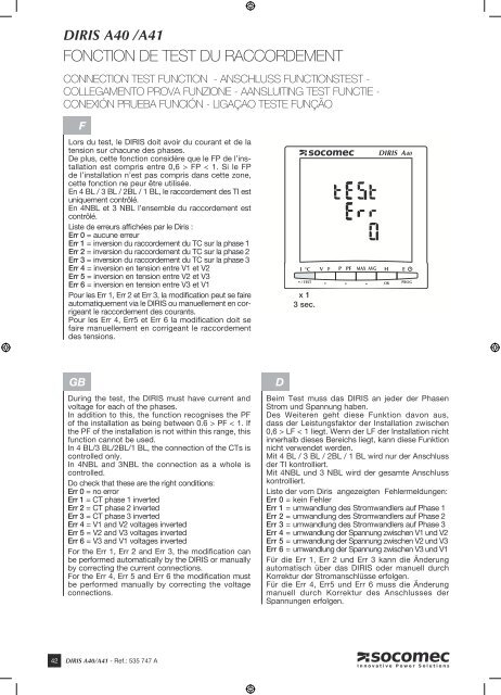
<strong>DIRIS</strong> <strong>A40</strong> /<strong>A41</strong>FONCTION DE TEST DU RACCORDEMENTCONNECTION TEST FUNCTION - ANSCHLUSS FUNCTIONSTEST -COLLEGAMENTO PROVA FUNZIONE - AANSLUITING TEST FUNCTIE -CONEXIÓN PRUEBA FUNCIÓN - LIGAÇAO TESTE FUNÇÃOFLors du test, le <strong>DIRIS</strong> doit avoir du courant et de latension sur chacune des phases.De plus, cette fonction considère que le FP de l’installationest compris entre 0,6 > FP < 1. Si le FPde l’installation n’est pas compris dans cette zone,cette fonction ne peur être utilisée.En 4 BL / 3 BL / 2BL / 1 BL, le raccordement des TI estuniquement contrôlé.En 4NBL et 3 NBL l’ensemble du raccordement estcontrôlé.Liste de erreurs affichées par le Diris :Err 0 = aucune erreurErr 1 = inversion du raccordement du TC sur la phase 1Err 2 = inversion du raccordement du TC sur la phase 2Err 3 = inversion du raccordement du TC sur la phase 3Err 4 = inversion en tension entre V1 et V2Err 5 = inversion en tension entre V2 et V3Err 6 = inversion en tension entre V3 et V1Pour les Err 1, Err 2 et Err 3, la modification peut se faireautomatiquement via le <strong>DIRIS</strong> ou manuellement en corrigeantle raccordement des courants.Pour les Err 4, Err5 et Err 6 la modification doit sefaire manuellement en corrigeant le raccordementdes tensions.x 13 sec.GBDuring the test, the <strong>DIRIS</strong> must have current andvoltage for each of the phases.In addition to this, the function recognises the PFof the installation as being between 0.6 > PF < 1. Ifthe PF of the installation is not within this range, thisfunction cannot be used.In 4 BL/3 BL/2BL/1 BL, the connection of the CTs iscontrolled only.In 4NBL and 3NBL the connection as a whole iscontrolled.Do check that these are the right conditions:Err 0 = no errorErr 1 = CT phase 1 invertedErr 2 = CT phase 2 invertedErr 3 = CT phase 3 invertedErr 4 = V1 and V2 voltages invertedErr 5 = V2 and V3 voltages invertedErr 6 = V3 and V1 voltages invertedFor the Err 1, Err 2 and Err 3, the modification canbe performed automatically by the <strong>DIRIS</strong> or manuallyby correcting the current connections.For the Err 4, Err 5 and Err 6 the modification mustbe performed manually by correcting the voltageconnections.DBeim Test muss das <strong>DIRIS</strong> an jeder der PhasenStrom und Spannung haben.Des Weiteren geht diese Funktion davon aus,dass der Leistungsfaktor der Installation zwischen0,6 > LF < 1 liegt. Wenn der LF der Installation nichtinnerhalb dieses Bereichs liegt, kann diese Funktionnicht verwendet werden.Mit 4 BL / 3 BL / 2BL / 1 BL wird nur der Anschlussder TI kontrolliert.Mit 4NBL und 3 NBL wird der gesamte Anschlusskontrolliert.Liste der vom Diris angezeigten Fehlermeldungen:Err 0 = kein FehlerErr 1 = umwandlung des Stromwandlers auf Phase 1Err 2 = umwandlung des Stromwandlers auf Phase 2Err 3 = umwandlung des Stromwandlers auf Phase 3Err 4 = umwandlung der Spannung zwischen V1 und V2Err 5 = umwandlung der Spannung zwischen V2 und V3Err 6 = umwandlung der Spannung zwischen V3 und V1Für die Err 1, Err 2 und Err 3 kann die Änderungautomatisch über das <strong>DIRIS</strong> oder manuell durchKorrektur der Stromanschlüsse erfolgen.Für die Err 4, Err5 und Err 6 muss die Änderungmanuell durch Korrektur des Anschlusses derSpannungen erfolgen.42 <strong>DIRIS</strong> <strong>A40</strong>/<strong>A41</strong> - Ref.: 535 747 A