pdf - Univerzitet u Nišu
pdf - Univerzitet u Nišu
pdf - Univerzitet u Nišu

You also want an ePaper? Increase the reach of your titles
YUMPU automatically turns print PDFs into web optimized ePapers that Google loves.
General<br />
SEMINARSKI RAD IZ MIKROPROCESORSKIH SISTEMA<br />
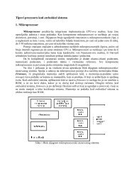
The Intel 8255A is a general purpose programmable I/O device which is designed for<br />
use with all Intel and most other microprocessors. It provides 24 I/O pins which may<br />
be individually programmed in 2 groups of 12 and used in 3 major modes of<br />
operation.<br />
In MODE 0, each group of 12 I/O pins may be programmed in sets of 4 and 8 to be<br />
inputs or outputs. In MODE 1, each group may be programmed to have 8 lines of<br />
input or output. 3 of the remaining 4 pins are used for handshaking and interrupt<br />
control signals. MODE 2 is a strobed bi-directional bus configuration.<br />
The 8255 is a 40 pin integrated circuit (IC), designed to perform a variety of interface<br />
functions in a computer environment. The 8255 wasn't originally designed to be<br />
connected to the Z80. It was manufactured by Intel for the 8080 microprocessor.<br />
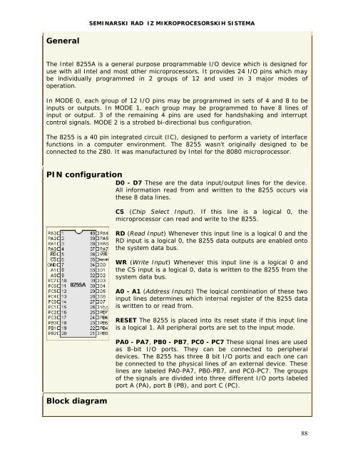
PIN configuration<br />
D0 - D7 These are the data input/output lines for the device.<br />
All information read from and written to the 8255 occurs via<br />
these 8 data lines.<br />
Block diagram<br />
CS (Chip Select Input). If this line is a logical 0, the<br />
microprocessor can read and write to the 8255.<br />
RD (Read Input) Whenever this input line is a logical 0 and the<br />
RD input is a logical 0, the 8255 data outputs are enabled onto<br />
the system data bus.<br />
WR (Write Input) Whenever this input line is a logical 0 and<br />
the CS input is a logical 0, data is written to the 8255 from the<br />
system data bus.<br />
A0 - A1 (Address Inputs) The logical combination of these two<br />
input lines determines which internal register of the 8255 data<br />
is written to or read from.<br />
RESET The 8255 is placed into its reset state if this input line<br />
is a logical 1. All peripheral ports are set to the input mode.<br />
PA0 - PA7, PB0 - PB7, PC0 - PC7 These signal lines are used<br />
as 8-bit I/O ports. They can be connected to peripheral<br />
devices. The 8255 has three 8 bit I/O ports and each one can<br />
be connected to the physical lines of an external device. These<br />
lines are labeled PA0-PA7, PB0-PB7, and PC0-PC7. The groups<br />
of the signals are divided into three different I/O ports labeled<br />
port A (PA), port B (PB), and port C (PC).<br />
88