HP rp5700 Illustrated Parts and Service Map - Business Support ...
HP rp5700 Illustrated Parts and Service Map - Business Support ...
HP rp5700 Illustrated Parts and Service Map - Business Support ...

You also want an ePaper? Increase the reach of your titles
YUMPU automatically turns print PDFs into web optimized ePapers that Google loves.
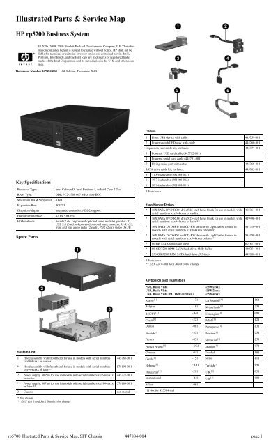
<strong>Illustrated</strong> <strong>Parts</strong> & <strong>Service</strong> <strong>Map</strong><br />
<strong>HP</strong> <strong>rp5700</strong> <strong>Business</strong> System<br />
© 2006, 2009, 2010 Hewlett-Packard Development Company, L.P. The information<br />
contained herein is subject to change without notice. <strong>HP</strong> shall not be<br />
liable for technical or editorial errors or omissions contained herein. Intel,<br />
Pentium, Intel Inside, <strong>and</strong> the Intel logo are trademarks or registered trademarks<br />
of the Intel Corporation <strong>and</strong> its subsidiaries in the U. S. <strong>and</strong> other countries.<br />
Document Number 447884-004. 4th Edition, December 2010<br />
Key Specifications<br />
Processor Type: Intel Celeron D, Intel Pentium 4, or Intel Core 2 Duo<br />
RAM Type: DDR PC2-5300 667 MHz, non-ECC<br />
Maximum RAM <strong>Support</strong>ed: 4 GB<br />
Expansion Bus: PCI 2.3<br />
Graphics Adapter Integrated controller. ADD2 support.<br />
Hard drive interface: SATA 3.0 Gb/s<br />
I/O Interfaces: Serial (2 std. or powered optional some models), parallel (1),<br />
USB 2.0 (6 std. + 4 powered optional some models), RJ-45 (1),<br />
front <strong>and</strong> rear audio jacks (2 each), PS/2 (2 ea), video DSUB<br />
Spare <strong>Parts</strong><br />
System Unit<br />
1 Hood assembly with front bezel for use in models with serial numbers<br />
xxx944xxxx or earlier<br />
445765-001<br />
* Hood assembly with front bezel for use in models with serial numbers<br />
xxx944xxxx or later **<br />
578190-001<br />
2 Power supply, 80Plus for use in models with serial numbers xxx944xxxx<br />
or earlier<br />
445771-001<br />
* Power supply, 80Plus for use in models with serial numbers xxx944xxxx<br />
or later **<br />
578189-001<br />
3 Chassis not spared<br />
* Not shown<br />
** EUP Lot 6 <strong>and</strong> Jack Black color change<br />
Cables<br />
1 Front USB device with cable 445759-001<br />
2 Power switch/LED assy with cable 445760-001<br />
Expansion card cable kit, includes: 445777-001<br />
3 Powered USB card cable (445792-001)<br />
4 Powered serial card cable (445791-001)<br />
5 Flying serial port with cable 445768-001<br />
SATA drive cable kit, includes: 445763-001<br />
6 11.8-inch cable (381868-013)<br />
6 19.7-inch cable (381868-012)<br />
6 20.9-inch cable (381868-011)<br />
* Not shown<br />
Mass Storage Devices<br />
* 16X SATA DVD-ROM drive5.25-inch bezel blank for use in models with<br />
serial numbers xxx944xxxx or earlier<br />
405761-001<br />
* 16X SATA DVD-ROM drive5.25-inch bezel blank for use in models with<br />
serial numbers xxx944xxxx or later **<br />
419496-001<br />
* 16X SATA DVD±RW <strong>and</strong> CD-RW drive with LightScribe for use in<br />
models with serial numbers xxx944xxxx or earlier<br />
447310-001<br />
* 16X SATA DVD±RW <strong>and</strong> CD-RW drive with LightScribe for use in<br />
models with serial numbers xxx944xxxx or later **<br />
581059-001<br />
* 80-GB SATA solid-state drive 607817-001<br />
* 80-GB\7200 RPM SATA hard drive, 8MB buffer 440754-001<br />
* 250-GB\7200 RPM SATA hard drive, 3.5-inch 449980-001<br />
* Not shown<br />
** EUP Lot 6 <strong>and</strong> Jack Black color change<br />
Keyboards (not illustrated)<br />
PS/2, Basic Vista<br />
USB, Basic Vista<br />
USB, Basic Vista (BG 1650 certified)<br />
435302-xxx<br />
435382-xxx<br />
435384-xxx<br />
Arabic [1] -171 [1]<br />
LA Spanish -161<br />
Belgian -181 [1]<br />
Netherl<strong>and</strong>s -331<br />
BHCSY [1] -B41 [1]<br />
Norwegian -091<br />
Czech [1] -221 Polish [1] -121<br />
Danish -081 Portuguese [1] -131<br />
Finnish [1] -351 [1]<br />
Russian -251<br />
French -051 [1]<br />
Slovakian -231<br />
French Arabic [1] -DE1 [1]<br />
Spanish -071<br />
German -041 Swedish -101<br />
[1]<br />
Greek -151 Swiss -111<br />
Hebrew [1] -BB1 [1]<br />
Turkish -141<br />
Hungarian [1] -211 [1]<br />
U.K. -031<br />
International -B31 U.S. [1] -001<br />
Italian -061<br />
[1] Not for 435384-xx1<br />
<strong>rp5700</strong> <strong>Illustrated</strong> <strong>Parts</strong> & <strong>Service</strong> <strong>Map</strong>, SFF Chassis 447884-004 page 1
St<strong>and</strong>ard <strong>and</strong> Optional Boards<br />
System Boards with thermal grease, alcohol pad, CPU socket cover, <strong>and</strong> mounting screws<br />
1 System board for use in models with serial numbers xxx944xxxx<br />
or earlier<br />
445757-001<br />
* System board for use in models with serial numbers xxx944xxxx<br />
or later **<br />
578188-001<br />
* System board for use in models with serial numbers xxx944xxxx<br />
or earlier (for Russia only)<br />
445764-001<br />
* System board for use in models with serial numbers xxx944xxxx<br />
or later (for Russia only) **<br />
592231-001<br />
Intel Celeron Processors with alcohol pad <strong>and</strong> thermal grease<br />
* #440, 512K cache, 2.0 GHz, 533 MHz FSB 449166-001<br />
Intel Pentium 4 Processors with alcohol pad <strong>and</strong> thermal grease<br />
* #E2160, 1 MB cache, 1.8 GHz, 800 MHz FXSB 449168-001<br />
Intel Core 2 Duo Processors with alcohol pad <strong>and</strong> thermal grease<br />
* #E7400, 3 MB cache, 2.80 GHz, 1066 FSB 581070-001<br />
* #E6400e, 2 MB cache, 2.13 GHz, 1066 FSB 450470-001<br />
Memory modules<br />
2 512 MB, PC2-5300 396520-001<br />
* 1 GB, PC2-6400 638637-001<br />
* 1 GB, PC2-5300 398038-001<br />
* 2 GB, PC2-6400 638638-001<br />
3 Riser card with mounting bracket <strong>and</strong> screws 445758-001<br />
Other boards<br />
* Powered serial port expansion card with cable 445775-001<br />
* Powered USB expansion card with cable 445776-001<br />
* DVI-D ADD2 graphics, LP 398333-001<br />
* LSI 56K modem, PCIe 490689-001<br />
* Wireless LAN adapter, 802.11 ABG, WorldWide 391866-001<br />
* Wireless LAN adapter, 802.11 ABG, North America 391866-002<br />
* <strong>HP</strong> Firewire IEEE 1394 PCIe x1 card 637591-001<br />
* NVIDIA NVS300, PCIe X1 graphics card 632827-001<br />
* Broadcom NetXtreme GbE Plus Card 377773-001<br />
* Not shown<br />
** EUP Lot 6 <strong>and</strong> Jack Black color change<br />
LP = Low profile<br />
FH = Full height<br />
Miscellaneous <strong>Parts</strong><br />
1 Chassis fan 445761-001<br />
2 Heatsink with alcohol pad <strong>and</strong> factory-applied thermal grease 445774-001<br />
* Mouse, PS2, scroll type 390937-001<br />
* Mouse, PS2, optical 417966-001<br />
* Battery, real-time clock 153099-001<br />
3 Front bezel without mounting screws for use in models with serial numbers<br />
xxx944xxxx or earlier<br />
445766-001<br />
* Front bezel without mounting screws for use in models with serial numbers<br />
xxx944xxxx or later **<br />
578191-001<br />
4 Internal speaker 445762-001<br />
5 Fan duct 445767-001<br />
6 Tower st<strong>and</strong> for use in models with serial numbers xxx944xxxx or earlier 445770-001<br />
* Tower st<strong>and</strong> for use in models with serial numbers xxx944xxxx<br />
or later **<br />
578193-001<br />
* 5.25-inch bezel blank for use in models with serial numbers xxx944xxxx<br />
or earlier<br />
335937-001<br />
* 5.25-inch bezel blank for use in models with serial numbers xxx944xxxx<br />
or later **<br />
570838-001<br />
* Not shown<br />
** EUP Lot 6 <strong>and</strong> Jack Black color change<br />
Power Supply Cable Connections<br />
CABLE<br />
DESIGNATOR<br />
DEVICE<br />
P1 System board., 24-pin<br />
P2 CPU power, 6-pin<br />
P3 Powered USB port expansion card<br />
P4 Powered serial port expansion card<br />
P5 2nd SATA hard drive<br />
P6 1st SATA hard drive<br />
P7 Optical drive<br />
<strong>rp5700</strong> <strong>Illustrated</strong> <strong>Parts</strong> & <strong>Service</strong> <strong>Map</strong>, SFF Chassis 447884-004 page 2
System Board<br />
System Board Connectors <strong>and</strong> Jumpers (position of some untitled components<br />
may vary in location)<br />
E16 ROM recovery P21 Powered COM port card<br />
E49 Password P126 COM2 connector<br />
E50 CMOS PCI1 PC riser<br />
J31 PCI express x1 slot P60 SATA0<br />
J41 ADD 2 card socket P61 SATA1<br />
P1 Main power P62 SATA2<br />
P3 CPU power P70 Chassis fan<br />
P5 Power button/LED XBT1 Real-time-clock battery<br />
P6 Internal speaker XU1 Processor<br />
P10 Front USB XU19/<br />
U19<br />
SPI ROM <strong>and</strong> socket<br />
P11 USB0 Powered USB card XMM1 DIMM 1<br />
P12 USB1 Powered USB card XMM2 DIMM 2<br />
P16 &<br />
P127<br />
COMx power configuration<br />
jumpers<br />
P17 COMx power configuration<br />
jumpers<br />
System Setup <strong>and</strong> Boot<br />
XMM3 DIMM 3<br />
XMM4 DIMM 4<br />
Basic system information regarding system information, setup, power management, hardware,<br />
<strong>and</strong> passwords is maintained in the Setup Utility held in the system ROM. The Setup Utility is<br />
accessed by pressing the F10 key when prompted (on screen) to do so during the boot sequence.<br />
If the screen prompt opportunity is missed, a restart will be necessary.<br />
Computer Setup Menu<br />
Heading Option/Description<br />
File System Information - Lists the following main system specifications:<br />
• Product name<br />
Memory size/speed/ no. channels<br />
SKU number (some<br />
Integrated MAC Address<br />
models)<br />
System BIOS<br />
Processor type/speed/step- Chassis serial number<br />
ping<br />
Cache Size (L1/L2)<br />
Asset tracking number<br />
Storage<br />
About - Displays copyright notice.<br />
Set Time <strong>and</strong> Date - Allows you to set system time <strong>and</strong> date.<br />
Flash System ROM (some models) - Allows you to select a drive containing<br />
a new BIOS.<br />
Replicated Setup - Save to Removable Media <strong>and</strong> Restore from Removable<br />
Media<br />
Default Setup<br />
Save Current Settings as Default<br />
Restore Factory Settings as Default<br />
Apply Defaults <strong>and</strong> Exit - Applies the selected default settings <strong>and</strong><br />
clears any established passwords.<br />
Ignore Changes <strong>and</strong> Exit - Exits Computer setup without applying or<br />
saving any changes.<br />
Save Changes <strong>and</strong> Exit - Saves changes to system configuration or<br />
default settings <strong>and</strong> exits Computer Setup.<br />
Device Configuration - Lists all installed BIOS-controlled storage<br />
devices. The following options are available:<br />
Hard disk<br />
Multisector Transfers (ATA disks only)<br />
Translation Mode (ATA disks only)<br />
Translation Parameters (ATA disks only)<br />
Default Values IDE/SATA<br />
Storage Options -<br />
Removable Media Boot<br />
BIOS DMA Data Transfers<br />
SATA Emulation-IDE RAID - SATA 0 <strong>and</strong> 2, SATA 1<br />
DPS Self-Test - Allows you to execute self-tests on ATA hard drives.<br />
Boot Order -<br />
Allows you to specify boot order.<br />
Shortcut to Temporary Override Boot Order<br />
Computer Setup Menu (Continued)<br />
Heading Option / Description<br />
Security Setup Password - Allows you to set <strong>and</strong> enable the setup (Administrator)<br />
password.<br />
Power-On Password - Allows you to set <strong>and</strong> enable power-on password.<br />
Password Options - When any password exists allows you to lock legacy<br />
resources, enable/disable network server mode, specify password<br />
requirement for warm boot, <strong>and</strong> allows you to enable/disable Setup<br />
Browse Mode.<br />
Embedded Security (some models) - Allows you to enable/disable<br />
Embedded Security <strong>and</strong> power-on authentication support, reset device to<br />
factory settings, enable/disable power-on authentication, <strong>and</strong> reset<br />
authentication credentials.<br />
Device Security (some models) - Enables/disables all I/O ports, audio,<br />
network controllers, <strong>and</strong> embedded security devices.<br />
Network <strong>Service</strong> Boot - Enables/disables boot from OS on a server.<br />
System IDs - Allows you to set Asset tag, ownership tag, chassis serial<br />
number, UUID, <strong>and</strong> keyboard locale setting.<br />
DriveLock Security - Allows you to assign/modify a hard drive password<br />
for added security.<br />
OS Security - Allows you to enable/disable Data Execution Prevention,<br />
OS management of Enabled Security Devices, reset Embedded Security<br />
Devices, <strong>and</strong> Intel Virtualization Technology.<br />
Setup Security Level - allows changing some options outside of F10<br />
setup<br />
Power OS Power Management - Allows you to enable/disable Runtime Power<br />
Management, ACPI S3 Hard Disk Reset, <strong>and</strong> ACPI S3 PS2 Mouse<br />
Wakeup. Also allows you to improve Idle Power Savings <strong>and</strong> to permit<br />
system to awaken when USB device is inserted.<br />
Hardware Power Management - Allows you to enable/disable SATA bus<br />
power management.<br />
Thermal - Allows you to control minimum permitted fan idle speed.<br />
Advanced Fea- Power-On Options - Allows you to set:<br />
tures<br />
POST mode - QuickBoot, FullBoot, or FullBoot every 1-30 days.<br />
POST messages - Enable/disable<br />
MEBx Setup prompt - Enable/disable or hidden/displayed<br />
F9 prompt - Enable/disable<br />
F10 prompt - Enable/disable<br />
F11 prompt - hidden/displayed<br />
F12 prompt - Enable/disable<br />
Factory Recovery Boot <strong>Support</strong> - Enable/disable<br />
Option ROM prompt - Enable/disable<br />
Remote wakeup boot source - Remote server/local hard drive<br />
After Power Loss - Off/on/previous state<br />
POST delay - None, 5, 10, 15, or 20 seconds<br />
I/O APIC mode - Enable/disable<br />
Hyperthreading - Enable/disable<br />
Limit CPUID<br />
Execute Memory Test (some models) -Restarts computer <strong>and</strong> executes<br />
POST memory test.<br />
BIOS Power-On - Allows you to set the computer to turn on at a preset<br />
time.<br />
Onboard Devices - Allows you to set resources or disable onboard system<br />
devices.<br />
PCI Devices - Lists installed PCI devices with their IRQ settings <strong>and</strong><br />
allows you to reconfigure IRQ or disable devices.<br />
PCI VGA Configuration - Allows you to specify which VGA controller<br />
will be used when multiple video adapters are available.<br />
Bus Options (some models) - Allows you to enable/disable PCI SERR#<br />
Generation <strong>and</strong> PCI VGA palette snooping.<br />
Device Options - Allows you to set:<br />
Printer Mode - Bi-Directional, EPP & ECP, Output Only<br />
Num Lock state at power-on - off/on<br />
S5 Wake on LAN - enable/disable<br />
Processor cache - enable/disable<br />
Unique Sleep State Blink Patterns<br />
Integrated video - enable/disable<br />
Internal speakers (some models)<br />
Monitor racking - enable/disable<br />
NIC PXE Option ROM Download - enable/disable<br />
System Hardware Interrupts<br />
IRQ System Function IRQ System Function<br />
0 Timer Interrupt 8 Real-Time Clock<br />
1 Keyboard 9 Unused<br />
2 Interrupt Controller Cascade 10 Unused, available for PCI<br />
3 Serial Port (COM B) 11 Unused, available for PCI<br />
4 Serial Port (COM A) 12 Mouse<br />
5 Unused, available for PCI 13 Coprocessor<br />
6 Diskette Drive 14 Primary ATA (IDE) Controller<br />
7 Parallel Port (LPT 1) 15 Secondary ATA (IDE) Controller<br />
<strong>rp5700</strong> <strong>Illustrated</strong> <strong>Parts</strong> & <strong>Service</strong> <strong>Map</strong>, SFF Chassis 447884-004 page 3
Failsafe Boot Block ROM<br />
The computer comes with a reprogrammable flash system ROM (read only memory). To<br />
upgrade the ROM, download the latest ROM BIOS image from the <strong>HP</strong> Web site (www.hp.com)<br />
<strong>and</strong> follow the online GUI/instructions.<br />
Your system ROM includes a Failsafe Boot Block that is protected during the flash process <strong>and</strong><br />
allows the computer to be restarted in the unlikely event of an unsuccessful ROM flash.<br />
If the system detects an invalid system ROM during the boot sequence, the Failsafe Boot Block<br />
attempts to locate a valid BIOS image on removable media. To recover from the Boot Block<br />
recovery mode complete the following steps:<br />
Boot Block Recovery<br />
1. Remove any bootable media from the computer <strong>and</strong> turn off power.<br />
2. Insert a flash drive or CD containing the ROM BIOS.<br />
3. Turn on power to the system.<br />
4. The system will automatically flash the ROM. After a successful flash, the system will either<br />
automatically restart or prompt the user to unplug the unit, wait 5 seconds, reattach the power<br />
cord, <strong>and</strong> then press the power button.<br />
Password Security<br />
Establishing a Setup password:<br />
1. Turn on or restart the computer. If you are in Windows, click Start > Shut Down ><br />
Restart.<br />
2. As soon as the computer is turned on, press F10 when the monitor light turns green to enter<br />
Computer Setup. Press Enter to bypass the title screen, if necessary. If you do not press F10<br />
when prompted, a restart will be necessary.<br />
3. Select Security > Setup Password <strong>and</strong> follow the instructions on the screen.<br />
4. Before exiting, click File > Save Changes <strong>and</strong> Exit.<br />
Establishing a Setup password:<br />
1. Turn on or restart the computer. If you are in Windows, click Start > Shut Down ><br />
Restart.<br />
2. As soon as the computer is turned on, press F10 when the monitor light turns green to enter<br />
Computer Setup. Press Enter to bypass the title screen, if necessary. If you do not press F10<br />
when prompted, a restart will be necessary.<br />
3. Select Security > Power-On Password <strong>and</strong> follow the instructions on the screen.<br />
Before exiting, click File > Save Changes <strong>and</strong> Exit.<br />
Changing a password:<br />
1. Turn on or restart the computer. If you are in Windows, click Start> Shut Down > Restart.<br />
To change the Setup password, go to step 2.<br />
To change the Power-on password, go to step 3.<br />
2. To change the Setup password, as soon as the computer is turned on, press F10 when the<br />
monitor light turns green to enter Computer Setup. Press Enter to bypass the title screen, if<br />
necessary.<br />
3. When the key icon appears, type your current password, a slash (/) or alternate de-limiter<br />
character, your new password, another slash (/) or alternate delimiter character, <strong>and</strong> your new<br />
password again as shown:<br />
current password/new password/new password.<br />
NOTE: Type the new password carefully since the actual characters do not appear on the<br />
screen.<br />
4. Press ENTER.<br />
The new password will take effect the next time the computer is restarted.<br />
Deleting a password<br />
1. Turn on or restart the computer. If you are in Windows, click Start > Shut Down > Restart.<br />
To delete the Setup password, go to step 2.<br />
To delete the Power-On password, go to step 3.<br />
2. To change the Setup password, as soon as the computer is turned on, press F10 when the<br />
monitor light turns green to enter Computer Setup. Press Enter to bypass the title screen, if<br />
necessary.<br />
3. When the key icon appears, type your current password followed by a slash (/) or alternate<br />
delimiter character as shown. Example: currentpassword/<br />
4. Press Enter.<br />
Security Features<br />
NOTE:<br />
For more information about Setup Utilities refer to the Computer Setup Menu on the previous<br />
page or in the <strong>Service</strong> Reference Guide.<br />
Diagnostic Functions<br />
Diagnostic functions are provided by the Setup Utility (in system ROM) <strong>and</strong> by Insight Diagnostics.<br />
Insight Diagnostics provides detailed system information including:<br />
Processor type <strong>and</strong> speed<br />
Memory amount, mapping, <strong>and</strong> integrity<br />
Hardware peripheral availability/settings<br />
Hard drive type, space used/available<br />
System identification, asset tracking<br />
Insight Diagnostics may be found on the Documentation <strong>and</strong> Diagnostics CD that shipped with<br />
the computer. The tool may also be downloaded from the hp Web site using the following procedure:<br />
1. Go to http://www.hp.com<br />
2. Click the Software <strong>and</strong> Download driver link.<br />
3. Enter the product number (for example, dc7700) in the text box <strong>and</strong> press the Enter key.<br />
4. Select the specific product.<br />
5. Select the OS.<br />
6. Click the Diagnostics link.<br />
7. Select <strong>HP</strong> Insight Diagnostics Offline Edition.<br />
8. Select the proper language <strong>and</strong> click Download.<br />
NOTE: The download includes instructions on how to create a bootable CD. The SoftPaq<br />
number is SP33665 or later.<br />
Error Conditions <strong>and</strong> Messages<br />
Feature Purpose<br />
Device Boot Disabling Prevents booting from <strong>and</strong> or all of these<br />
devices: Internal or external USB, Internal<br />
ODD, or Internal FDD<br />
Security Option Prevents use of computer until password is<br />
entered. Can apply to both initial startup <strong>and</strong><br />
restart.<br />
BIOS Write Protect Restricts ability to change ROM BIOS without<br />
approval.<br />
USB Controller Allows you to disable or enable all USB<br />
devices.<br />
How It Is<br />
Established<br />
Setup Utilities<br />
Setup Utilities<br />
Setup Utilities.<br />
Setup Utilities<br />
Diagnostic LEDs<br />
LED Color LED Activity State/Message<br />
Power Green On Computer on<br />
Power Green 1 blink every 2 seconds Normal Suspend Mode<br />
Power Red 1 blink every second followed<br />
by a 2 second pause<br />
CPU thermal shutdown<br />
Power Red 3 blinks, 1 blink every second<br />
followed by a 2 second pause<br />
Processor not installed<br />
Power Red 4 blinks, 1 blink every second<br />
followed by a 2 second pause<br />
Power failure (power supply overload)<br />
Power Red 5 blinks, 1 blink every second<br />
followed by a 2 second pause<br />
Pre-video memory error<br />
Power Red 6 blinks, 1 blink every second<br />
followed by a 2 second pause<br />
Pre-video graphics error<br />
Power Red 7 blinks, 1 blink every second<br />
followed by a 2 second pause<br />
System board failure (ROM<br />
Power Red 8 blinks, 1 blink every second<br />
followed by a 2 second pause<br />
Invalid ROM based on Checksum<br />
Power Red 9 blinks, 1 blink every second<br />
followed by a 2 second pause<br />
System powers on but is unable to boot<br />
Power Red 10 blinks, 1 blink every second<br />
followed by a 2 second pause<br />
Bad option card<br />
none none System does not power on <strong>and</strong><br />
LEDs are not flashing<br />
System unable to power on<br />
Common POST Error Messages<br />
Screen<br />
Message Beeps Probable Cause Recommended Action<br />
101-Option<br />
ROM Error<br />
103-System<br />
Board<br />
Failure<br />
164-<br />
Memory Size<br />
Error<br />
<strong>and</strong><br />
201<br />
Memory Error<br />
214-DIMM<br />
Configuration<br />
Warning<br />
301-, 304-Keyboard<br />
error<br />
501-Display<br />
Adapter Failure<br />
1720-SMART<br />
Hard Drive<br />
Detects Imminent<br />
Failure<br />
1796-SATA<br />
Cabling Error<br />
1801-Microcode<br />
Patch<br />
Error<br />
NOTES: L = long, S = short<br />
1L, 1S 1. System ROM checksum<br />
error.<br />
2. Expansion card.<br />
3. CMOS corruption.<br />
4. System board.<br />
1. Verify ROM, reflash if required<br />
2. Remove suspected card, reboot<br />
3. Clean CMOS memory, reboot<br />
4. Replace system board<br />
none DMA, timers 1. Clear CMOS memory.<br />
2. Remove expansion board.<br />
3. Replace system board.<br />
2S Incorrect memory configuration<br />
none Populated DIMM configuration<br />
is not optimized<br />
1. Run Setup (F10).<br />
2. Check DIMMs for proper<br />
seating, type, <strong>and</strong> <strong>HP</strong><br />
compatibility.<br />
3. Remove DIMMs singularly <strong>and</strong><br />
reboot to isolate faulty DIMM.<br />
Rearrange the DIMMs so that<br />
each channel has the same amount<br />
of memory.<br />
none Keyboard failure. Check keyboard connection or<br />
keys. Replace keyboard. If 304,<br />
possible system board problem.<br />
1L, 2S Graphics controller. 1. Reseat graphics card.<br />
2. Check monitor connection.<br />
3. Replace graphics card.<br />
none Hard drive is about to fail. Run drive protection system test if<br />
available. Check for firmware<br />
patch for erroneous error message.<br />
none One or more SATA devices<br />
are improperly attached.<br />
none Processor not supported by<br />
ROM BIOS.<br />
Ensure SATA0 <strong>and</strong> SATA1 are<br />
used before any other SATA connectors.<br />
1. Upgrade BIOS to proper<br />
version.<br />
2. Change the processor.<br />
Clearing CMOS<br />
1. Shut down the system <strong>and</strong> disconnect the power cord from the power outlet.<br />
2. Remove the computer cover.<br />
3. Locate the E50 (CMOS) jumper <strong>and</strong> move the jumper from pins 1-2 to pins 2-3.<br />
4. Leave the jumper on pins 2-3 for 5 seconds then, return the jumper to pins 1-2.<br />
5. Replace the computer cover <strong>and</strong> reconnect the power cord.<br />
6. Turn on the computer <strong>and</strong> allow it to start.<br />
<strong>rp5700</strong> <strong>Illustrated</strong> <strong>Parts</strong> & <strong>Service</strong> <strong>Map</strong>, SFF Chassis 447884-004 page 4