HP CX4 & XFP Interface Cards User Guide - HP Business Support ...
HP CX4 & XFP Interface Cards User Guide - HP Business Support ...
HP CX4 & XFP Interface Cards User Guide - HP Business Support ...

You also want an ePaper? Increase the reach of your titles
YUMPU automatically turns print PDFs into web optimized ePapers that Google loves.
<strong>HP</strong> <strong>CX4</strong> & <strong>XFP</strong> <strong>Interface</strong> <strong>Cards</strong><br />
<strong>User</strong> <strong>Guide</strong><br />
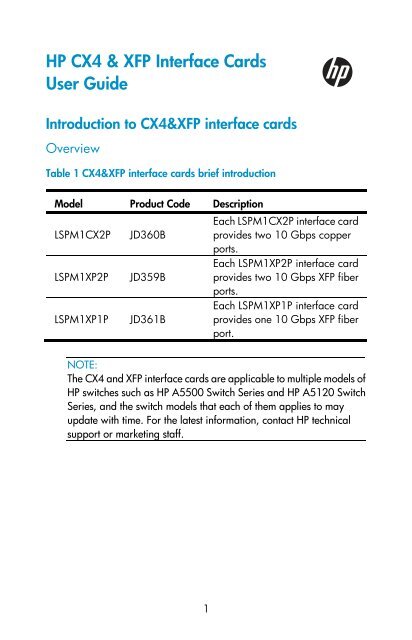
Introduction to <strong>CX4</strong>&<strong>XFP</strong> interface cards<br />
Overview<br />
Table 1 <strong>CX4</strong>&<strong>XFP</strong> interface cards brief introduction<br />
Model Product Code Description<br />
Each LSPM1CX2P interface card<br />
LSPM1CX2P JD360B provides two 10 Gbps copper<br />
ports.<br />
Each LSPM1XP2P interface card<br />
LSPM1XP2P JD359B provides two 10 Gbps <strong>XFP</strong> fiber<br />
ports.<br />
Each LSPM1XP1P interface card<br />
LSPM1XP1P JD361B provides one 10 Gbps <strong>XFP</strong> fiber<br />
port.<br />
NOTE:<br />
The <strong>CX4</strong> and <strong>XFP</strong> interface cards are applicable to multiple models of<br />
<strong>HP</strong> switches such as <strong>HP</strong> A5500 Switch Series and <strong>HP</strong> A5120 Switch<br />
Series, and the switch models that each of them applies to may<br />
update with time. For the latest information, contact <strong>HP</strong> technical<br />
support or marketing staff.<br />
1
LSPM1CX2P<br />
Appearance of the interface card<br />
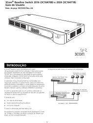
Figure 1 Front panel of the LSPM1CX2P interface card<br />
Description of LSPM1CX2P<br />
Each LSPM1CX2P interface card provides two 10 Gbps copper ports<br />
and supports <strong>CX4</strong> standards. You can connect a <strong>CX4</strong> port to another<br />
<strong>CX4</strong> port through a <strong>CX4</strong> cable provided by <strong>HP</strong>. For more information<br />
about the supported <strong>CX4</strong> cables, see Table 2. The supported max<br />
transmission distance is 3 m (9.84 ft), which is only suitable for short-haul<br />
transmission.<br />
Table 2 <strong>CX4</strong> cables supported by LSPM1CX2P<br />
Cable<br />
<strong>HP</strong> X230 Local<br />
Connect 50cm<br />
<strong>CX4</strong> Cable<br />
<strong>HP</strong> X230 Local<br />
Connect 100cm<br />
<strong>CX4</strong> Cable<br />
<strong>HP</strong> X230 Local<br />
Connect <strong>CX4</strong><br />
300cm Cable<br />
Product<br />
code<br />
JD363B<br />
2<br />
Connector Cable length<br />
0.5m (19.69<br />
in)<br />
4X<br />
JD364B 1m (39.37 in)<br />
Infiniband<br />
JD365A<br />
3m (118.11<br />
in)
NOTE:<br />
• <strong>HP</strong> recommends that you use <strong>CX4</strong> cables of <strong>HP</strong> on the LSPM1CX2P.<br />
• The types of <strong>CX4</strong> cables may update with time. For information<br />
about them, contact <strong>HP</strong> technical support or marketing staff.<br />
Description of LEDs<br />
There is an LED for each port on the panel of the interface card.<br />
Table 3 Description of LEDs on the LSPM1CX2P<br />
LED Status Description<br />
Port LED of the<br />
LSPM1CX2P<br />
interface card<br />
The port is normally connected. The<br />
On LED blinks quickly when the port is<br />
sending or receiving data.<br />
Off The port is not up.<br />
NOTE:<br />
Port LED of the LSPM1CX2P interface card is not affected by the port<br />
mode switching button on your switch. For more information about<br />
the port mode switching button, see the installation guide of the<br />
switch.<br />
LSPM1XP2P<br />
Appearance of the interface card<br />
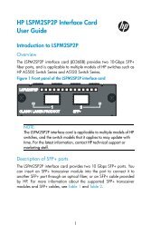
Figure 2 Front panel of the LSPM1XP2P interface card<br />
3
Description of LSPM1XP2P<br />
Each LSPM1XP2P interface card provides two 10-Gigabit <strong>XFP</strong> fiber ports.<br />
You can insert an <strong>XFP</strong> transceiver module into the port to connect it to<br />
another <strong>XFP</strong> port through an optical fiber. For more information about the<br />
supported <strong>XFP</strong> transceiver modules and fibers, see Table 4.<br />
Table 4 <strong>XFP</strong> transceiver modules and fibers supported by LSPM1XP2P<br />
<strong>XFP</strong> transceiver module Product code<br />
<strong>HP</strong> X130 10G <strong>XFP</strong> LC SR Transceiver JD117B<br />
<strong>HP</strong> X130 10G <strong>XFP</strong> LC LR Transceiver JD108B<br />
<strong>HP</strong> X135 10G <strong>XFP</strong> LC ER Transceiver JD121A<br />
<strong>HP</strong> X130 10G <strong>XFP</strong> LC ZR Transceiver JD107A<br />
NOTE:<br />
• <strong>HP</strong> recommends that you use <strong>XFP</strong> transceiver modules of <strong>HP</strong> on the<br />
LSPM1XP2P.<br />
• The types of <strong>XFP</strong> transceiver modules may update with time. For<br />
information about them, contact <strong>HP</strong> technical support or marketing<br />
staff.<br />
• For the models and specifications of each kind of <strong>XFP</strong> transceiver<br />
modules, see the <strong>HP</strong> A-Series Switches Transceiver Modules <strong>User</strong><br />
<strong>Guide</strong> on the <strong>HP</strong> website.<br />
Description of LEDs<br />
For information about the description of LEDs, see Table 3.<br />
4
LSPM1XP1P<br />
Appearance of the interface card<br />
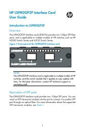
Figure 3 Front panel of the LSPM1XP1P interface card<br />
Description of LSPM1XP1P<br />
Each LSPM1XP1P interface card provides one 10-Gigabit <strong>XFP</strong> fiber port.<br />
You can insert an <strong>XFP</strong> transceiver module into the port to connect it to<br />
another <strong>XFP</strong> port through an optical fiber. For more information about the<br />
supported <strong>XFP</strong> transceiver modules and fibers, see Table 4.<br />
Description of LEDs<br />
For information about the description of LEDs, see Table 3.<br />
Installing an interface card<br />
The following tools are needed for the installation and removal of an<br />
interface card:<br />
• Phillips screwdriver<br />
• ESD-preventive wrist strap<br />
NOTE:<br />
The installation tools are not shipped together with <strong>HP</strong>’s devices.<br />
Prepare them yourself.<br />
5
Installing the interface card<br />
Installing the interface card to the switch<br />
NOTE:<br />
The procedure of installing the interface card to different models of<br />
<strong>HP</strong> switches is similar. This user guide takes the A5500-24G EI<br />
Switch with 2 <strong>Interface</strong> Slots (JD377A) as an example.<br />
Follow these steps to install the interface card to the switch:<br />
Step1 Wear an ESD-preventive wrist strap, and make sure that the<br />
ESD-preventive wrist strap makes good skin contact and is properly<br />
grounded.<br />
Step2 Loosen the mounting screws of the filler panel on the interface<br />
card slot of the switch with a Phillips screwdriver and remove the<br />
filler panel, as shown in Figure 4.<br />
Figure 4 Install an interface card (I)<br />
Step3 Holding the fastening screws on the front panel of the interface<br />
card, gently push the interface card in along the slot guide rail until<br />
the interface card is in close contact with the switch, as shown in<br />
Figure 5.<br />
Step4 Tighten the captive screws with a Phillips screwdriver to fix the<br />
interface card.<br />
6
Figure 5 Install an interface card (II)<br />
NOTE:<br />
• Keep the removed filler panel properly for future use.<br />
• When tightening the fastening screws at both sides of the interface<br />
card with a screwdriver or an electric screwdriver, make sure that<br />
the torque is not bigger than 0.4 N-m.<br />
Removing the interface card<br />
Follow these steps to remove the interface card:<br />
Step1 Wear an ESD-preventive wrist strap, and make sure that the<br />
ESD-preventive wrist strap makes good skin contact and is properly<br />
grounded.<br />
Step2 Use a Phillips screwdriver to loosen the captive screws at both<br />
sides of the interface card until all spring pressure is released.<br />
Step3 Pull the interface card towards you along the guide rails, until it<br />
completely comes out of the switch chassis.<br />
7
CAUTION:<br />
When installing or removing an interface card, note the following<br />
guidelines:<br />
• Do not touch the surface-mounted components directly with your<br />
hands.<br />
• Do not use too much force in the operation.<br />
• After removing an interface card, if no new interface card is to be<br />
installed, install the filler panel as soon as possible to prevent dust<br />
and ensure normal ventilation in the switch.<br />
Installing an <strong>XFP</strong> transceiver module<br />
To avoid component damage caused by improper installation, carefully<br />
read the SFP/SFP+/<strong>XFP</strong> Transceiver Modules Installation <strong>Guide</strong> from the<br />
<strong>HP</strong>'s website before installing the <strong>XFP</strong> transceiver modules.<br />
Installing and removing the dedicated <strong>CX4</strong> cable<br />
Installing the dedicated <strong>CX4</strong> cable<br />
Figure 6 <strong>CX4</strong> cable<br />
CAUTION:<br />
Make sure that you have installed the LSPM1CX2P interface card<br />
before installing dedicated <strong>CX4</strong> cables.<br />
Follow these steps to install the dedicated <strong>CX4</strong> cable:<br />
Step1 Wear an ESD-preventive wrist strap and make sure it is properly<br />
grounded. Then unpack the dedicated <strong>CX4</strong> cable.<br />
Step2 Horizontally insert the plug of the dedicated <strong>CX4</strong> cable into the<br />
<strong>CX4</strong> port of the switch and pay attention to the direction of the plug<br />
when plugging it.<br />
8
Removing the dedicated <strong>CX4</strong> cable<br />
Follow these steps to remove the dedicated <strong>CX4</strong> cable:<br />
Step1 Wear an ESD-preventive wrist strap and make sure the<br />
ESD-preventive wrist strap properly grounded.<br />
Step2 Holding the plug of the <strong>CX4</strong> cable, pull the handle at the end of<br />
the plug to horizontally unplug the plug of the <strong>CX4</strong> cable from the<br />
<strong>CX4</strong> port of the switch.<br />
CAUTION:<br />
• Dedicated <strong>CX4</strong> cable is hot swappable.<br />
• Make sure that the cable bending radius is no less than eight times<br />
of the cable diameter when dedicated <strong>CX4</strong> cable is connected.<br />
Verifying the installation<br />
When the switch runs properly, check whether the interface card is<br />
operating properly according to the status of the Port LED on the interface<br />
card.<br />
9
Documentation<br />
To find related documents, browse to the Manuals page of the <strong>HP</strong><br />
<strong>Business</strong> <strong>Support</strong> Center website:<br />
http://www.hp.com/support/manuals<br />
© Copyright 2011 Hewlett-Packard Development Company, L.P.<br />
The information in this document is subject to change without notice.<br />
BOM: 3101A0DB<br />
Part number: 5998-1726<br />
Version: 6PW101-20110629<br />
59981726<br />
10