S U R G I C A L T E C H N I Q U E - Small Bone Innovations
S U R G I C A L T E C H N I Q U E - Small Bone Innovations
S U R G I C A L T E C H N I Q U E - Small Bone Innovations
Create successful ePaper yourself
Turn your PDF publications into a flip-book with our unique Google optimized e-Paper software.
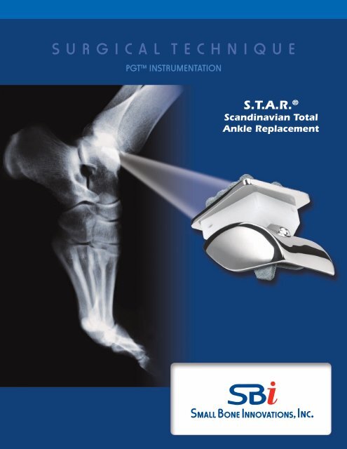
S U R G I C A L T E C H N I Q U E<br />
PGT Instrumentation<br />
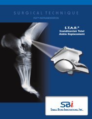
S.T.A.R. ®<br />
Scandinavian Total<br />
Ankle Replacement
S.T.A.R.® Scandinavian Total Ankle Replacement<br />
SURGICAL TECHNIQUE<br />
CONTENTS<br />
Description<br />
Overview 1<br />
Components 2<br />
Indications / Contraindications<br />
Contraindications, Warnings/Precautions & Post-Operative Management 3<br />
Surgical Technique<br />
Placement of The Tibial Alignment Guide 6<br />
Preparation of the Talus 8<br />
Anterior/Posterior Cut Guide 11<br />
Medial/Lateral Cut Guide 12<br />
Final Tibial Preparation 16<br />
Talar Component Implantation 17<br />
Tibial Component Implant 17<br />
Closure 18<br />
Implant Dimensions 19<br />
Postoperative Treatment 21<br />
Obtaining X-ray 21<br />
Additional Information 21<br />
Caution: United States federal law restricts these devices to sale by or on the order of a physician.
Description<br />
Overview<br />
The S.T.A.R.® Ankle system includes three functional components, and a set of customized accessory instruments that<br />
are used in the surgical procedure. The three principal components of the prosthesis are:<br />
• A metal tibial component with titanium plasma spray coating;<br />
• An ultra high molecular weight polyethylene mobile bearing; and<br />
• A metal talar component with titanium plasma spray coating.<br />
The mobile bearing articulates on the tibial and talar metal implant surfaces, as shown in the photograph of the three<br />
components of the S.T.A.R.® Ankle system below:<br />
Tibial Plate<br />
Mobile Bearing<br />
Talar Component<br />
The S.T.A.R.® Ankle is designed to replace a portion of the tibial and talar components of the normal ankle joint, while<br />
preserving range of motion as much as possible.<br />
There are two bearing surfaces in the S.T.A.R.® Ankle: (1) the interface between the upper side of the mobile bearing<br />
and the facing surface of the tibial plate, and (2) the interface between the lower surface of the mobile bearing and the<br />
facing surface of the talar component. The tibial plate has one flat surface and one surface with two raised cylindrical<br />
barrels oriented in the anterior/posterior direction. The upper flat surface of the mobile bearing slides against the flat<br />
surface of the tibial plate. The projecting cylinders of the tibial plate serve to fix the device to bone at the distal tibia. The<br />
lower surface of the mobile bearing is concave, fitting against the convex upper surface of the talar component.<br />
1
The mobile bearing design of the device is intended to reduce the shear and torque forces on the bearing, which can<br />
lead to loosening of either metal component, and to decrease stress at the metal/bone interface. The sloped sides are<br />
designed to improve the weight bearing characteristics of the talar component.<br />
Components<br />
Tibial Plate<br />
When viewed from the top, the tibial plate has a trapezoidal shape with rounded corners. This component is manufactured<br />
from cobalt chromium molydenum (CoCrMo) per ASTM F-75. This wedge is shaped to conform to the existing<br />
anatomy and, thereby, reduces the need to remove excess bone from inside the joint. On the proximal surface of the<br />
tibial plate, two parallel cylindrical barrels are positioned equidistant from the center of the plate running anterior to<br />
posterior for bone fixation. These cylinders must be inserted into hard subchondral bone.<br />
When viewed from the side, the plate is 2.5mm thick. The distal surface of the plate on which the mobile bearing articulates<br />
is flat and polished. The flat surface is designed to match the distal tibial cut.<br />
Tibial plates are available in five sizes with varying widths and lengths: extra-small (30mm x 30mm), small (32mm x<br />
30mm), medium (32.5mm x 35mm), large (33mm x 40mm), and extra large (33.5mm x 45mm).<br />
The tibial plate is coated on the bone-opposing surfaces with a titanium plasma spray coating. The tibial plate is intended<br />
to be press-fit without the use of cement, and should rest on anterior and posterior cortical bone.<br />
Mobile Bearing<br />
The polyethylene mobile bearing is manufactured from Ultra High Molecular Weight Polyethylene (“UHMWPE”), which<br />
is machined from medical grade extruded plate stock and conforms to ASTM F-648. The proximal surface of the mobile<br />
bearing is flat. The distal or talar surface is concave and has a central radial groove running from anterior to posterior.<br />
The walls are straight, and a 0.5mm stainless steel x-ray marker wire is placed 2mm from the proximal surface. The wall<br />
height varies to provide spacer thicknesses of 6mm, 7mm, 8mm, 9mm, and 10mm. Revision mobile bearings are available<br />
in sizes of 11mm, 12mm, 13mm, and 14mm.<br />
Talar Component<br />
The talar component is designed as an anatomical prosthesis to cover the talar dome, anterior, posterior, and medial and<br />
lateral facets. Like the tibial plate, this component is manufactured from CoCrMo. The talar component is designed to<br />
minimize the amount of bone that must be removed. From the apex of the dome, the walls slope outwards to conform<br />
to the normal bone anatomy. The component is offered in five sizes: extra-extra-small (28mm x 29mm), extra-small<br />
(30mm x 31mm), small (34mm x 35mm), medium (36mm x 35mm), and large (38mm x 35mm), and in both left and<br />
right-sided configurations.<br />
Viewed from the side, the proximal surface of the talar component is dome-shaped to conform to the talar dome of<br />
the normal ankle. A small, raised half-cylindrical ridge runs from anterior to posterior in the medial-lateral center of the<br />
dome. The purpose of this ridge is to constrain the medial/lateral motion of the mobile bearing.<br />
As with the tibial plate, the talar component is also provided with a titanium plasma spray coating.<br />
2<br />
S.T.A.R. ® Scandinavian Total Ankle Replacement Surgical Technique
Indications / Contraindications<br />
The SBi Scandinavian Total Ankle Replacement (S.T.A.R.® Ankle) is indicated for use as a non-cemented implant to<br />
replace a painful arthritic ankle joint due to osteoarthritis, post-traumatic arthritis or rheumatoid arthritis.<br />
Contraindications, Warnings/Precautions & Post-Operative Managment<br />
Contraindications<br />
• Active or prior deep infection in the ankle joint or adjacent bones<br />
• Skeletal immaturity<br />
• <strong>Bone</strong> stock inadequate to support the device including:<br />
o Severe osteoporotic or osteopenic condition or other conditions resulting in poor bone quality<br />
o Avascular necrosis of the talus<br />
o Prior surgery and/or injury that has adversely affected ankle bone quality<br />
• Malalignment or severe deformity of involved or adjacent anatomic structures including:<br />
o Hindfoot or forefoot malalignment precluding plantigrade foot<br />
o Significant malalignment of the knee joint<br />
• Insufficient ligament support that cannot be repaired with soft tissue stabilization<br />
• Neuromuscular disease resulting in lack of normal muscle function about the affected ankle<br />
• Lower extremity vascular insufficiency demonstrated by Doppler arterial pressure<br />
• Charcot joint or peripheral neuropathy that may lead to Charcot joint of the affected ankle<br />
• Prior arthrodesis at the ankle joint<br />
• Poor skin and soft tissue quality about the surgical site<br />
Warnings/Precautions<br />
• Only implant the S.T.A.R.® Ankle after adequate training and familiarity with the surgical technique manual, to avoid<br />
increased risk of device failure due to improper surgical technique.<br />
• Do not use S.T.A.R.® Ankle components in combination with prosthesis components made by other manufacturers,<br />
because design, material, or tolerance differences may lead to premature device and/or functional failure. Components<br />
of the system have been specifically designed to work together.<br />
• To ensure proper implantation of the S.T.A.R.® Ankle, use the instrumentation that is supplied with the system in<br />
accordance with the surgical technique manual.<br />
• The trial prostheses should not be implanted.<br />
• Examine instruments for wear or damage before use. While rare, intra-operative instrument breakage may occur.<br />
Instruments that have experienced excessive use or force may be susceptible to breakage.<br />
• The safety and efficacy of the S.T.A.R.® Ankle have not been studied in patients weighing > 250 lbs.<br />
• Always determine that the patient does not have a possible allergy to the implant/prosthesis material before selecting<br />
the S.T.A.R.® implant to minimize the risk of an allergic response.<br />
• Discard all damaged or mishandled implants. Do not reuse implants and components. Although the implant may<br />
appear undamaged, it may have small defects and internal stress patterns which may lead to early failure of the<br />
device.<br />
• Do not resterilize. Do not use implants or components if the package is damaged or has been opened prior to planned<br />
use.<br />
3
• Always exercise care in selecting the proper type and size of implant. Size and shape of the human bone place<br />
restrictions on the size and shape of the implant, potentially limiting device function.<br />
• Do not contour or bend an implant because it may reduce its fatigue strength and cause failure under load. Correct<br />
handling of the implant is extremely important.<br />
• Immediately post-operative through two weeks, a patient should not bear any weight on the implanted S.T.A.R.®<br />
Ankle. Certain vigorous physical activities (e.g., basketball, football) and trauma to the joint replacement may cause<br />
early failure of the S.T.A.R.® Ankle. Please refer to the section titled ‘‘Post-operative Management’’ for additional restrictions.<br />
• Appropriate selection, placement and fixation of the S.T.A.R.® Ankle components are critical factors which affect<br />
implant service life. Improper selection, placement and fixation of the implant components may result in early implant<br />
failure. As in the case of all prosthetic implants, the durability of these components is affected by numerous biologic,<br />
biomechanic and other extrinsic factors which limit their service life. Accordingly, strict adherence to the indications,<br />
contraindications, precautions and warnings for this product is essential to potentially maximize service life.<br />
Post-Operative Management<br />
For a minimum of two weeks after surgery, the patient should not bear weight on the operated ankle. The patient should<br />
keep the ankle elevated as much as possible while limiting all physical activities. Partial weight-bearing may begin at 2<br />
to 3-weeks post-operative and gradually increase until the patient is fully weight-bearing at 4 to 6-weeks post-operative.<br />
The ankle cast should typically be removed six weeks post-operative.<br />
4<br />
S.T.A.R. ® Scandinavian Total Ankle Replacement Surgical Technique
S.T.A.R. ® Surgical Technique<br />
Su r g i c a l Pr o c e d u r e<br />
A small bump is placed beneath the ipsilateral hip to rotate the<br />
ankle so that the line of the medial malleolus is perpendicular to<br />
the operating table. After the foot and ankle have been correctly<br />
positioned, the leg is elevated for about 2 minutes, and a high thigh<br />
tourniquet is inflated with an appropriate amount of pressure for<br />
the size of the patient’s leg and foot. A longitudinal 20 cm incision<br />
is centered over the ankle immediately lateral to the anterior tibial<br />
tendon (FIGURE 1). The incision is deepened to the ankle joint while<br />
retracting the extensor hallucis longus and the neurovascular bundle<br />
laterally (FIGURE 2).<br />
The superficial branch of the peroneal nerve in the foot is visible<br />
and must be retracted carefully to the lateral aspect of the ankle. It is<br />
frequently necessary to sacrifice one small branch of this nerve that<br />
innervates the great toe. The tendon sheath of the extensor hallucis<br />
longus is now incised in line with the skin incision. Every effort<br />
is made to avoid opening the tendon sheath of the anterior tibial<br />
tendon, since this may cause difficulty in closure. After the tendon<br />
sheath of the extensor hallucis longus is opened, the deep peroneal<br />
nerve and artery are identified and are gently retracted. The ankle<br />
capsular tissues are incised in line with the skin incision and then<br />
are elevated and mobilized exposing the medial malleolus, and lateral<br />
malleoli. If the capsule is of sufficient quality save it to close over<br />
the prosthesis. It is important to avoid the release of the anterior<br />
talofibular ligament as this may lead to lateral instability. The ankle<br />
joint is distracted slightly, and hypertrophic synovium, intraarticular<br />
loose bodies or periarticular spurs are resected. Osteophytes on the<br />
anterior distal tibia are removed to visualize the tibial plafond.<br />
Self-retaining retractors should be avoided when possible, to<br />
eliminate excess pressure on the skin edges. Hand retractors<br />
should be frequently repositioned to minimize the risk of tissue<br />
trauma.<br />
Figure 1<br />
Figure 2<br />
5
Placement of the Tibial Alignment Guide<br />
A 3.2 mm self drilling pin is inserted into the anterior tibial<br />
tubercle and perpendicular to the long axis of the tibia. The proximal<br />
portion of the tibial alignment guide is positioned over this fixation<br />
pin and the superior screw on the guide is tightened, locking the<br />
tibial alignment guide superiorly. The tibial cutting guide is positioned<br />
on an adjustable bar. (FIGURE 3) The guide is extended half of<br />
the length of the bar to allow for proximal and distal adjustments<br />
depending upon how much of the plafond requires resection. The<br />
distal aspect of the tibial alignment guide is positioned on the bar<br />
approximately 5 mm proximal to the tibial plafond. (This will allow a<br />
cut just proximal to the proximal extent of the articular surface.)<br />
A T Guide can be inserted into the cutting block to aid in assessing<br />
the rotational and varus/valgus orientation of the tibial cutting<br />
guide (FIGURE 3). An osteotome can also be placed along the medial<br />
gutter of the ankle joint to aid in visualization when setting proper<br />
rotational orientation of the guide. Attach the parallel alignment rod<br />
to the midportion of the tibial alignment guide to confirm that the<br />
tibial alignment guide is parallel to the tibial diaphysis in both A/P<br />
and lateral planes with use of the C-arm (FIGURE 3). The distal portion<br />
of the alignment guide is secured with the use of 2.4 mm drill<br />
pins. The level of the tibial resection is checked with the use of the<br />
angel wing (FIGURES 4, 5, 6).<br />
T Guide<br />
Parallel alignment rod<br />
Figure 3<br />
Figure 4<br />
Figure 5<br />
The angel wing is placed in the cutting slot of the tibial resection<br />
guide to set the cutting guide for a mimimum of 5mm distal tibial<br />
resection. There are 7 pegs each extending 5 mm from the central<br />
blade of the angel wing that are used to guage the amount of tibial<br />
resection. For reference, the pegs are spaced every 10 mm’s.<br />
The inferior tip of the closest peg is adjusted (using C-arm lateral<br />
view) to align with the most superior aspect of the distal tibial<br />
plafond (FIGURE 5). This adjustment is made by using the gear key<br />
on the tibial cutting guide, dialing it distal or proximal. The set screw<br />
is then tightened to lock the guide prior to cutting. (In very loose<br />
ankle joints, there may be increased ability to distract the talus<br />
inferiorly. In this case, the surgeon may choose to remove only<br />
4mm of bone from the distal tibia. With a very tight ankle joint,<br />
where there is little ability to distract the talus distalward, one<br />
may need to resect 6 or 8 mm of distal tibial bone.)<br />
10 mm increments<br />
Angel Wing<br />
Figure 6<br />
6<br />
S.T.A.R. ® Scandinavian Total Ankle Replacement Surgical Technique
Medial and lateral adjustment of the cutting guide is done using<br />
the gear key to minimize the risk of notching either of the malleoli.<br />
(FIGURES 7 & 8). If additional stability is needed to secure the cutting<br />
guide 2.4 mm pins are placed in the most proximal pin holes. There<br />
are additional pin holes situated in two milimeter increments proximally.<br />
If additional tibial resection is necessary, the cutting guide can<br />
be moved proximally and secured on these pins. The saw capture is<br />
next placed on the distal tibial cutting guide. And the medial pin is<br />
placed in the slot defining the end of the tibial cut and protecting<br />
the medial malleolus from notching. The lateral pin is then placed<br />
angled toward the center of the tibia to protect the fibula from notching.<br />
(FIGURES 9 & 10)<br />
Figure 7<br />
At this point, it is recommended to insert two K-wires into the<br />
medial malleoli to help prevent accidental fracture.<br />
The transverse distal tibial cut is then made. The saw should be<br />
directed at a 90 degree angle to the long axis of the tibia (FIGURE<br />
10). Angling of the saw either medially or laterally may lead to notching<br />
of the malleoli if protecting pins are not used. Following this, a<br />
reciprocating saw is used to cut upward in a proximal direction along<br />
the inner edge of the medial malleolus to connect the transverse<br />
tibial osteotomy. Care should be taken not to penetrate too deeply<br />
with the saw blade during the transverse or vertical saw cuts.<br />
All resected tibial bone is removed. This may be done as a single<br />
piece, or more commonly in several smaller pieces. The resection is<br />
checked using both AP and lateral fluoroscopic views to insure resection<br />
of the distal tibia is complete and at the appropriate angles.<br />
Gear Key<br />
Figure 8<br />
Holes for pins to protect malleoli<br />
Figure 9<br />
Figure 9 Figure 10<br />
7
Preparation of the Talus<br />
Pin holes for securing position of block<br />
relative to talus<br />
The appropriate talar cutting guide is next inserted onto the tibial<br />
alignment guide. (FIGURES 11a+b & 12). The goal of the talar resection<br />
is to remove approximately 4 mm of bone from the talar dome.<br />
During the initial talar cut, the foot is held in a plantigrade position<br />
as the talus is pushed cephalad against the prepared surface of the<br />
tibia (or the tibial spacer block). There is a “0” cutting guide for normal<br />
or tight ankle joints, and cutting guides with 2, 4, and 6 mm<br />
spacers for relaxed joints.<br />
Care should be taken to hold the foot perpendicular to the long<br />
axis of the tibia. Holding the foot and ankle in excessive dorsiflexion<br />
will shift the final position of the talar implant anteriorly.<br />
Holding the foot and ankle in excess plantarflexion will result in<br />
positioning the talar component posteriorly.<br />
During talar dome resection, it is important to protect the malleoli.<br />
Pins can be placed in the ends of the cutting slot and malleable<br />
retractors or other angled retractors can be placed in the medial and<br />
lateral gutters.<br />
The angel wing can also be used here to verify the correct position<br />
of the talus prior to placement of fixation pins. Fixation pin holes<br />
are available on the medial and lateral aspects of the talar cutting<br />
guide to aid in maintaining the position of the talus during the talar<br />
osteotomy. After the osteotomy of the talus is completed, the bone<br />
fragment of the talar dome is removed and the joint is evaluated to<br />
assess the space following removal of both tibial and talar articular<br />
surfaces. A joint space evaluator instrument is placed into the prepared<br />
joint space. (FIGURE 13) One end of the instrument measures 12<br />
mm while the other end measures 9 mm. The 12 mm end of the joint<br />
space evaluator is positioned between the cut surfaces. A minimum<br />
of 12 mm is required as this is the space required for a 6 mm bearing<br />
with tibial and talar implants. If the 12 mm joint space evaluator does<br />
not fit, further tibial resection is required. The tibial cutting guide has<br />
pin holes marked for 2 mm and 4 mm recuts. (FIGURE 14) The cutting<br />
guide can be repositioned, and additional bone resected.<br />
Figure 11a<br />
Spacer for joints that are lax 2, 4 and 6 mm available<br />
Figure 11b<br />
9 mm<br />
Pin holes for recuts<br />
Figure 12<br />
12 mm<br />
Space evaluator<br />
Figure 13<br />
Figure 14<br />
8<br />
S.T.A.R. ® Scandinavian Total Ankle Replacement Surgical Technique
After insuring there is enough space for at least a 6 mm polyethylene<br />
bearing, the foot is plantar flexed to achieve better exposure of<br />
the talus. The talar sizer (FIGURE 15) is centered on cut surface of the<br />
dorsal talus to confirm that there is a minimum 12 mm A/P depth on<br />
this cut. (FIGURE 16a & b, Table 1) (All of the talar implants have a 12<br />
mm inside Anterior/Posterior dimension. The medial/lateral width<br />
varies depending upon the size of the talar component)<br />
Talar Component Outside Largest Dimension<br />
XXS XS S M LG<br />
ML Dimension 28 30 34 36 38<br />
AP Dimension 29 31 35 35 35<br />
Figure 15<br />
Table 1<br />
An appropriate sized talar component for a patient will leave<br />
3 mm of exposed talar surface on both the medial and lateral<br />
sides of the guide. Using a skin marker, outline the anterior corners<br />
of the talar sizer to aid in placement of the appropriate size<br />
datum.<br />
The above chart shows the outside dimensions of the talar components.<br />
A measurement of the distance between malleoli may be<br />
taken to ensure the appropriate size is selected. When the measurement<br />
is in-between sizes, select the smaller size.<br />
Figure 16a<br />
Figure 16b<br />
9
Next select the appropriate size datum (FIGURE 17) and mount it on<br />
the datum holder/distractor. (FIGURE 18)<br />
The holder/distractor with the datum attached is inserted into the<br />
ankle joint. (FIGURE 18) The datum is positioned within the outline<br />
marked on the talar from the sizer. Confirm the handle of the<br />
distractor is in line with the second metatarsal. This appropriately<br />
aligns the talar rotational position. Next using the C-arm, a lateral<br />
fluoroscopic view is obtained to confirm that the posterior top<br />
corner of the datum is beneath the center of the tibial prepared surface.<br />
The posterior top corner of the datum represents the center of<br />
the talus. Compress the handle on the distractor to firmly hold the<br />
datum in place. (FIGURE 18) Using shoulder pins, (FIGURE 19) the<br />
datum is secured to the talus. Start with the shortest pin (10 mm).<br />
If the datum needs to be repositioned or if the bone quality is poor,<br />
move to the longer pins. Pins should be advanced slowly into the<br />
bone using the pin driver (FIGURE 20) and the last few turns should<br />
be done by hand to avoid stripping the threads in the bone. It is<br />
critical at this at this point to insure that the datum is securely<br />
fixed, as your next four cuts are all based off of the position of<br />
the datum. (FIGURE 21)<br />
Holes for threaded fixation pins with shoulders<br />
Figure 17<br />
Figure 18<br />
Figure 19<br />
Figure 20<br />
Figure 21<br />
10<br />
S.T.A.R. ® Scandinavian Total Ankle Replacement Surgical Technique
Anterior/Posterior Cut Guide<br />
The posterior talar cut can be completed with or without the A/P<br />
talar cut guide. (FIGURE 22) When using the A/P talar cutting guide<br />
it is attached to the datum using the locking bolt. (FIGURE 23) After<br />
this cut is completed, attention is directed to the anterior aspect of<br />
the talus.<br />
The anterior talar mill (FIGURE 24) is used to prepare the anterior<br />
aspect of the talus. The mill is inserted until the collar abuts the A/P<br />
cutting guide. (FIGURE 25) A sweeping motion is made through<br />
both of the superior/inferior windows in the talar cutting guide to<br />
remove the anterior bone. (FIGURE 26) Take care to protect the soft<br />
tissues surrounding the medial and lateral aspects of the talus while<br />
using the mill. The A/P cutting guide, and all bone fragments are<br />
now removed.<br />
A/P Talar Cut Guide<br />
Figure 22<br />
Anterior talar mill use with wire driver, drill or TPS<br />
Figure 24<br />
Figure 23<br />
Figure 25 Figure 26<br />
11
Medial/Lateral Cut Guide<br />
Additional pin fixation holes if necessary<br />
Next, the M/L talar cut guide (FIGURE 27) is secured to the datum<br />
using the locking bolt. Using the reciprocating saw with the depth<br />
marking (FIGURE 28), the medial and lateral edges of the talus are<br />
cut.<br />
The saw blade is advanced only to the depth indicated by the<br />
marking on the saw blade to minimize risk of soft tissue damage.<br />
(FIGURE 29) Ideally 2 to 3 mm of bone is removed from the medial<br />
and lateral sides of the talus. The cuts should penetrate distally<br />
about 10 mm on the medial side, and about 17 mm on the lateral<br />
side. The blade is rotated until the top edge of the saw blade lines<br />
up with the line on the M/L talar cut guide. (FIGURES 30a+b) The<br />
blade is advanced anteriorly to complete the cut.<br />
Be cautious not to “lever” the blade too firmly against the<br />
guide and risk loosening of the fixation pins. Additional pin<br />
fixation holes may be used for extra stability if necessary.<br />
M/L Cut Guide<br />
Figure 27<br />
Saw Blade with Depth Marking<br />
Figure 28<br />
Move anterior<br />
to complete cut<br />
Figure 29<br />
Figure 30a<br />
Figure 30b<br />
12<br />
S.T.A.R. ® Scandinavian Total Ankle Replacement Surgical Technique
Use of the Extra <strong>Small</strong> (XS) and Extra Extra <strong>Small</strong> (XXS) talar<br />
instruments<br />
Because of the small size, the datum is incorporated into the guides<br />
for the XS and XXS talar resection guides. (FIGURES 31a & b)<br />
The talar sizer is used to mark the orientation of the talar<br />
component. (FIGURE 31c) Next the A/P cutting guide with datum<br />
(one piece) is loaded on the forceps. (FIGURE 32a) It is positioned in<br />
line with the second metatarsal and centered medial-laterally. Next<br />
a lateral view on the C-arm is taken to ensure placement of the A/P<br />
cutting guide directly over the center of the talus. The A/P guide is<br />
now secured with threaded shoulder pins, and the posterior cut is<br />
made with the oscillating saw. Next the anterior surface is milled.<br />
The A/P guide is removed using the pin driver. The M/L guide is<br />
loaded on the forceps and placed on the talus. (FIGURE 32b) The<br />
guide will sit flush against the milled anterior surface. (FIGURE<br />
32c) Make sure the M/L guide is centered in the Medial and Lateral<br />
plane. (FIGURE 32b) Pin it in place using the shoulder pins. (FIGURE<br />
32d) Make the medial and lateral cuts as previously described.<br />
Figure 31a<br />
Figure 31b<br />
Figure 31c<br />
Figure 32a<br />
Figure 32b<br />
Figure 32c<br />
Figure 32d<br />
13
The talar window trial is used to check that all talar cuts are complete<br />
and accurate. (FIGURES 34a+b) If the window trial does not fit, the<br />
bone rasp is used to remove excess unresected bone. (FIGURE 37)<br />
Preparation of the Keel<br />
Place two 2.4 mm pins in the anterior holes on talar window trial<br />
for additional stability during keel preparation. (FIGURE 35) The<br />
straight keel mill (FIGURE 36) is placed in the center slot of the<br />
window trial. The mill can be utilized with a drill or wire driver. The<br />
straight mill is pushed into the talar surface until it is flush with the<br />
stop on the mill and moved anteriorly on the slot. (FIGURES 37a+b)<br />
Slot for mill and broach<br />
Rasp<br />
Figure 33<br />
Pin holes<br />
Window Trial<br />
Figure 34a<br />
Figure 34b<br />
Keel Mill<br />
Figure 36<br />
Figure 35<br />
Figure 37a<br />
Figure 37b<br />
14<br />
S.T.A.R. ® Scandinavian Total Ankle Replacement Surgical Technique
The talar window trial is removed, and the keel broach is used to<br />
finish preparation of the keel slot. (FIGURE 38) When the keel broach<br />
is properly inserted to depth its angled top surface will align in the<br />
same plane as the posterior cut and the vertical face lines up with<br />
the edge formed by the intersection of the anterior and superior cut<br />
surfaces. (FIGURE 39)<br />
Replace the talar window trial to protect the talar cut surface during<br />
the final tibial preparation.<br />
Figure 38<br />
Figure 39<br />
Figure 40<br />
15
Final Tibial Preparation<br />
Height Adjustment Pin<br />
Use the ruler to measure the anterior-posterior dimension of the<br />
cut surface of the tibia. Determine the appropriate size of the tibial<br />
component such that the component will rest on cortical bone on<br />
both the anterior and posterior aspects of the tibia. (TABLE 2)<br />
Tibial Components<br />
X-<strong>Small</strong> <strong>Small</strong> Medium Large X-Large<br />
Width 30 32 32.5 33 33.5<br />
Depth 30 30 35 40 45<br />
Table 2<br />
Width<br />
Anterior<br />
Figure 41<br />
Depth<br />
Posterior<br />
The tibial size chosen is independent of the talar component size.<br />
The corresponding barrel guide is placed against the prepared tibial<br />
surface in the position that gives best anterior and posterior cortical<br />
coverage. The barrels need to be lined up in the M/L plane to be<br />
centered over the talar component. (FIGURE 41) A joint spacer, poly<br />
trial, or joint distractor may be used to apply pressure to the tibial<br />
barrel guide to keep it flush against the prepared tibial surface. (The<br />
bearing trial allows easier access for drilling the barrel holes.) The<br />
height adjustment pin is used to help stabilize the barrel guide while<br />
it is pinned with 2.4 mm pins. The barrel holes are drilled down to<br />
the stop using the 6.5 mm drill bit. After drilling the first barrel hole,<br />
place the barrel hole plug in the hole to insure precise spacing as the<br />
second hole is prepared. After drilling the barrel holes, the key hole<br />
broach is inserted into the barrel hole guide to remove the excess<br />
bone between the barrel hole and the distal tibial surface. (FIGURE<br />
42)<br />
All of the talar and tibial preparation is completed at this point. One<br />
can now assess the balance of the joint, and ligament tightness by<br />
doing trial reductions using the trial bearings.<br />
Figure 42<br />
16<br />
S.T.A.R. ® Scandinavian Total Ankle Replacement Surgical Technique
Talar Component Implantation<br />
The talar component keel is inserted over the anterior chamfer into<br />
the prepared keel slot. The implant is moved posteriorly so that<br />
the posterior edge of the keel aligns with the posterior edge of the<br />
prepared slot. The notched end of the joint space evaluator is placed<br />
on the anterior edge of the talar component for support during<br />
impaction. (FIGURE 44) The talar impactor is then used to evenly<br />
seat the implant. (FIGURE 45)<br />
Tibial Component Implantation<br />
Next the tibial component is mounted onto the tibial inserter<br />
locking it securely with the thumb screw. (FIGURE 46) The tibial component<br />
is inserted into the barrel holes, making sure the barrels are<br />
correctly aligned with the prepared holes. A mallet is used to gently<br />
drive the tibial component down to its ideal position. As the tibial<br />
component is being impacted, be sure it does not separate from the<br />
tibial cut. This can be accomplished by placing a poly trial against<br />
the tibial component after it has been driven down about half<br />
way. The anterior edge of the component should be flush with the<br />
anterior tibial cortex. A sponge is placed over the talar component<br />
to protect it while inserting the tibial component. Once the tibial<br />
implant is fully seated the thumb screw of the inserter is loosened<br />
and the tibial impactor is removed. Mobile bearing trials are then<br />
used to assess the appropriate height (6 – 10mm) for a trial reduction<br />
and to evaluate joint tension. After a satisfactory reduction is<br />
accomplished, the trial bearing is replaced by the appropriate final<br />
mobile bearing implant.<br />
Joint Space Evaluator with Notched End<br />
Figure 44<br />
Figure 45<br />
Figure 46<br />
17
Closure<br />
The entire wound is irrigated with antibiotic solution and, if needed,<br />
a closed suction drainage system is placed. The deep tissue<br />
and extensor retinaculum are closed in an interrupted fashion. The<br />
subcutaneous tissue is closed. Skin edges are approximated with an<br />
interrupted skin closure. A sterile compression dressing and posterior<br />
splint is applied with the ankle in a neutral position.<br />
18<br />
S.T.A.R. ® Scandinavian Total Ankle Replacement Surgical Technique
Implant Dimensions<br />
Tibial Components<br />
Material: CoCrMo Alloy and CP Titanium<br />
Item No.<br />
Cementless<br />
Size<br />
A<br />
mm<br />
B<br />
mm<br />
400-260 X-<strong>Small</strong> 30 30<br />
400-261 <strong>Small</strong> 32 30<br />
400-262 Medium 32.5 35<br />
400-263 Large 33 40<br />
400-264 X-Large 33.5 45<br />
Mobile Bearings<br />
Material: UHMWPE and Stainless Steel<br />
Item No.<br />
Height<br />
Primary<br />
400-140 6 mm<br />
400-141 7 mm<br />
400-142 8 mm<br />
400-143 9 mm<br />
400-144 10 mm<br />
Item No.<br />
Height<br />
Revision<br />
99-0028/11 11 mm<br />
99-0028/12 12 mm<br />
99-0028/13 13 mm<br />
99-0028/14 14 mm<br />
19
Implant Dimensions<br />
Talar Components<br />
Material: CoCrMo Alloy and CP Titanium<br />
Item No.<br />
Cementless<br />
Size<br />
Side<br />
A<br />
mm<br />
B<br />
mm<br />
400-250 XX-<strong>Small</strong> Right 28 29<br />
400-252 X-<strong>Small</strong> Right 30 31<br />
400-254 <strong>Small</strong> Right 34 35<br />
400-256 Medium Right 36 35<br />
400-258 Large Right 38 35<br />
Item No.<br />
Cementless<br />
Size<br />
Side<br />
A<br />
mm<br />
B<br />
mm<br />
400-251 XX-<strong>Small</strong> Left 28 29<br />
400-253 X-<strong>Small</strong> Left 30 31<br />
400-255 <strong>Small</strong> Left 34 35<br />
400-257 Medium Left 36 35<br />
400-259 Large Left 38 35<br />
20<br />
S.T.A.R. ® Scandinavian Total Ankle Replacement Surgical Technique
Postoperative Treatment<br />
For a minimum of two weeks after surgery, the patient should not bear weight on the operated ankle. The patient should keep the<br />
ankle elevated as much as possible while limiting all physical activities. Partial weight-bearing may begin at 2 to 3-weeks post-operative<br />
and gradually increase until the patient is fully weight-bearing at 4 to 6-weeks post-operative. The ankle cast should typically<br />
be removed six weeks post-operative unless a ligamentous reconstruction was carried out, in which case the cast is left on for a total<br />
of 8 weeks.<br />
Obtaining X-ray<br />
Suggestions for obtaining X-rays for patient follow-up:<br />
All X-rays should be taken using image intensification to provide straight frontal and lateral views. In the frontal views, the<br />
cylindrical anchoring segments of the Tibial Glide Plate must show as circular dots. The X-ray marking wire in the Sliding Core must<br />
form a straight horizontal line parallel to the Tibial Component.<br />
The Talar Component with its lateral wings appears as a rectangle where both the medial and the lateral part of the joint can be seen<br />
into. In the lateral projection, the Tibial Component should render the distal plateau as a straight line. The Talar Component shows<br />
only a straight line. The Talar Component shows only a straight view of one side wing of the Talar Cap.<br />
Additional Information<br />
More detailed information about our implants can be supplied upon request.<br />
Materials used for our orthopaedic implants:<br />
• CoCrMo alloy, ISO 5832-4/ASTM F75<br />
• Commercially Pure Titanium, ASTM F1580<br />
• Stainless Steel, ISO 5832-1/ASTM F138 / ASTM F139<br />
• UHMWPE, ISO 5834-2/ASTM F648<br />
Proper surgical procedures and techniques are necessarily the responsibility of the medical professional. Each surgeon must evaluate the appropriateness of the<br />
surgical technique used based on personal medical training and experience.<br />
The contents of this document are protected from unauthorized reproduction or duplication under U.S. federal law. Permission to reproduce this document<br />
(for educational/instructional use only) may be obtained by contacting <strong>Small</strong> <strong>Bone</strong> <strong>Innovations</strong>, Inc.<br />
Caution: United States federal law restricts the sale of this device to or on the order of a physician.<br />
21
Distributed in the USA by:<br />
<strong>Small</strong> <strong>Bone</strong> <strong>Innovations</strong>, Inc.<br />
SBi Customer Service: (800) 778-8837<br />
1380 South Pennsylvania Ave.<br />
Morrisville, PA 19067<br />
Fax (866) SBi-0002<br />
Technical Support: (866) SBi-TIPS<br />
www.totalsmallbone.com<br />
Distributed outside the USA by:<br />
<strong>Small</strong> <strong>Bone</strong> <strong>Innovations</strong> International<br />
ZA Les Bruyères - BP 28<br />
01960 Péronnas, France<br />
Tel: +33 (0) 474 21 58 19<br />
Fax: +33 (0) 474 21 43 12<br />
info-intl@totalsmallbone.com<br />
Copyright © <strong>Small</strong> <strong>Bone</strong> <strong>Innovations</strong>, Inc., 2009. All rights reserved.<br />
MKT 16012 Rev B. 08/09


