AH-10 Instruction Manual with parts list and wiring diagrams - Amaco
AH-10 Instruction Manual with parts list and wiring diagrams - Amaco
AH-10 Instruction Manual with parts list and wiring diagrams - Amaco

Create successful ePaper yourself
Turn your PDF publications into a flip-book with our unique Google optimized e-Paper software.
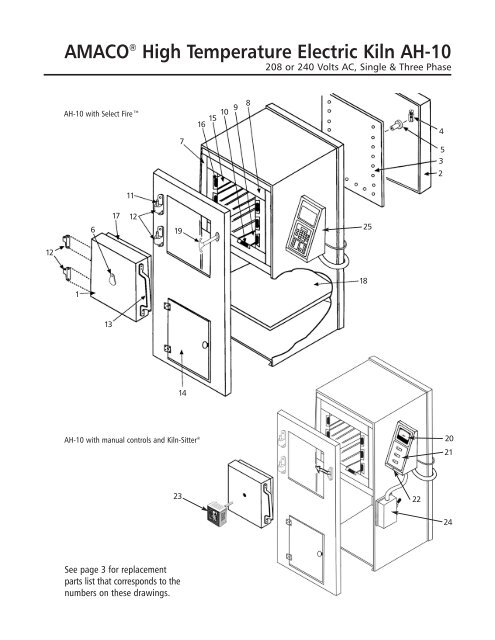
AMACO ® High Temperature Electric Kiln <strong>AH</strong>-<strong>10</strong><br />
208 or 240 Volts AC, Single & Three Phase<br />
<strong>AH</strong>-<strong>10</strong> <strong>with</strong> Select Fire<br />
7<br />
15<br />
16<br />
<strong>10</strong><br />
9<br />
8<br />
4<br />
5<br />
3<br />
2<br />
11<br />
6<br />
17<br />
12<br />
19<br />
25<br />
12<br />
1<br />
18<br />
13<br />
14<br />
<strong>AH</strong>-<strong>10</strong> <strong>with</strong> manual controls <strong>and</strong> Kiln-Sitter ®<br />
20<br />
21<br />
23<br />
22<br />
24<br />
See page 3 for replacement<br />
<strong>parts</strong> <strong>list</strong> that corresponds to the<br />
numbers on these drawings.
General Information<br />
The AMACO ® <strong>AH</strong>-<strong>10</strong> High Fire Kiln has a maximum attainable temperature of Cone <strong>10</strong> (2381ºF, 1305ºC). The <strong>AH</strong>-<strong>10</strong> is available <strong>with</strong><br />
manual control switches or the Select Fire Computer Control for precise control, convenience, <strong>and</strong> consistent results firing after<br />
firing. During every firing, pyrometric cones should be placed in the kiln so that they can be viewed through the peephole(s).<br />
This booklet contains a <strong>wiring</strong> diagram for the <strong>AH</strong>-<strong>10</strong> kiln, Select Fire Controller (single <strong>and</strong> three phase) <strong>and</strong> a <strong>parts</strong> <strong>list</strong> <strong>with</strong> accompanying<br />
drawing for the <strong>AH</strong>-<strong>10</strong> <strong>and</strong> Select Fire. Before installing the kiln, consult these <strong>diagrams</strong> for recommendations on electric<br />
service, fuses, etc.<br />
Also included <strong>with</strong> this booklet is an AMACO ® Electric Kilns Installation/Operation/Maintenance manual, which includes important<br />
information about selecting a location for your kiln, firing guidelines, <strong>and</strong> do-it-yourself instructions for replacing elements, plus<br />
complete programming <strong>and</strong> operating instructions for the Select Fire Controller.<br />
Operating Information for <strong>Manual</strong> Models <strong>with</strong> Kiln-Sitter ®<br />
The <strong>Amaco</strong> ® <strong>AH</strong>-<strong>10</strong> high temperature kiln is equipped <strong>with</strong> a fused safety switch box <strong>and</strong> three toggle switches. A pilot light indicates<br />
when the kiln is operating.<br />
Close kiln door <strong>and</strong> latch securely before firing. Turn safety switch to “ON”, place the appropriate cone in the Kiln-Sitter ® , <strong>and</strong> push<br />
the plunger button. NOTE: If the kiln is equipped <strong>with</strong> a KilnVent, it must be turned on prior to firing.<br />
The toggle switches operate as follows:<br />
LOW: Turn on any switch<br />
MEDIUM: Turn on any two switches<br />
HIGH: Turn on all three switches<br />
The time required for firing will depend on the temperature to be attained, the number of objects being fired, <strong>and</strong> electric current<br />
fluctuations. Approximate cycle times are as follows:<br />
LOW: approximately one hour<br />
MEDIUM: approximately one hour<br />
HIGH: until desired temperature is reached<br />
When firing time has been completed, turn off all switches <strong>and</strong> allow the kiln to cool overnight. If glazed pieces are removed from the<br />
kiln when the pieces are too hot, crazing may result due to sudden cooling. NOTE: Kilns equipped <strong>with</strong> a KilnVent will cool faster.<br />
Installation of Kiln<br />
Place kiln at least 18 inches from any existing wall at the sides <strong>and</strong> back. Connect kiln to an electric circuit which corresponds to that<br />
stamped on the kiln name plate. No. 6 gauge wire or larger should run from the power supply to the fused safety switch box on the<br />
kiln. 45 ampere fuses are required.<br />
Kiln Specifications <strong>AH</strong>-<strong>10</strong><br />
(Single phase <strong>and</strong> three phase)<br />
Voltage ................................................................................................................................................208 or 220-240 Volts AC only<br />
Amp Rating ..........................................................................................................................Single Phase: 35.1 at 208, 30.4 at 240V<br />
Three Phase: 22.1 at 208, 17.6 at 240V<br />
Kilowatt Rating ..............................................................................................................................................................................7.3<br />
Power Cord ............................................................50 amp <strong>with</strong> NEMA 6-50 plug (single phase) or NEMA 15-50 plug (three phase)<br />
Firing Speed Control ....................................................................................Three Toggle Switches or Select Fire Computer Control<br />
Maximum Temperature................................................................................................................................................2381°F, 1305°C<br />
Firing Chamber Dimensions (W x D x H) ........................................................................................................................15" x 21" x 18"<br />
Firing chamber Area ....................................................................................................................................................3.28 cubic feet<br />
Exterior Dimensions (W x D x H) ..............................................................................................................................37 1 ⁄2" x 37 3 ⁄4"* x 60"<br />
Elements ......................................................................................................Element Plates (holder <strong>with</strong> wires): 8 side <strong>and</strong> 4 bottom<br />
Shipping Weight ....................................................................................................................................................................790 lbs.<br />
*Width includes Select Fire or switches/pyrometer box. Depth is 60" <strong>with</strong> door open.<br />
2
REPLACEMENT PARTS LIST<br />
AMACO ® HIGH TEMPERATURE ELECTRIC KILN<br />
<strong>AH</strong>-<strong>10</strong><br />
Detail No. Part No. Description No. Parts/Kiln<br />
1 28250H Door Complete – No Hardware 1<br />
2 * Terminal Guard, back 1<br />
3 28256P CEM-FIL (back panel) 1<br />
4 28071F Terminal Lug #<strong>10</strong>NPW 24<br />
5 28034M Insulator P-3580 24<br />
6 29025C Peephole Cover (Select Fire models only) 1<br />
7 * Top Insulation 1<br />
7 * Bottom Insulation 1<br />
7 * Side Insulation 2<br />
7 * Back Insulation 1<br />
8 28266B Top Brick Set 1<br />
8 28267C Bottom Brick Set 1<br />
8 28266B Back Brick Set 1<br />
8 28269E Side Brick 2<br />
9 28273J Bottom Element Holder 4<br />
<strong>10</strong> 28275L Bottom Element Coil 208V 4<br />
<strong>10</strong> 28277N Bottom Element Coil 240V 4<br />
11 28072G Hinge Pin 2<br />
12 28073H Door Hinge 4<br />
13 28129H Door H<strong>and</strong>le 1<br />
14 * Cabinet Door 1<br />
15 28279B Side Element Holder 8<br />
16 28281T Side Element Coil 208V 8<br />
16 28283H Side Element Coil 240V 8<br />
17 28270F Door Brick, Set 1<br />
18 * Cabinet Shelf 1<br />
19 28151F Latch, Door 1<br />
20 28820P Pyrometer w/Thermocouple Set—Kiln-Sitter ® models only 1<br />
21 28063T Toggle Switch, 20 Amp—Kiln-Sitter ® models only 3<br />
22 28074J Pilot Light Assembly—Kiln-Sitter ® models only 1<br />
23 28741B Kiln-Sitter ® LT-3 Model w/Limit Timer, 208/240V Single Phase—Kiln-Sitter ® models only 1<br />
23 28739Y Kiln-Sitter ® LT-3 Model w/Limit Timer, 208/240V Three Phase—Kiln-Sitter ® models only 1<br />
24 28<strong>10</strong>8W Safety Switch 60 Amp Three Phase—Kiln-Sitter ® models only 1<br />
** Relay for Kiln-Sitter ® , Three Phase only 1<br />
** Fuse, Dual Element, 45 Amp for single phase 1<br />
** Fuse, Dual Element, 45 Amp for three phase 1<br />
25 Select Fire Control Box (see pages 4-5 for detail) 1<br />
OPTIONAL EQUIPMENT<br />
29968J Master KilnVent, 115V, 1.1 Amp 1<br />
24122S Select Fire (wall mount) Single Phase 1<br />
24123T Select Fire (wall mount) Three Phase 1<br />
11389A <strong>AH</strong>-<strong>10</strong> Furniture Kit 1<br />
* Special Order Item. Allow extra time for shipment.<br />
** Available at hardware/home improvement stores.<br />
3
Three Relay, Single Phase<br />
SELECT FIRE Kiln Controller for <strong>AH</strong>-<strong>10</strong><br />
Warning:<br />
Disconnect power<br />
before servicing kiln.<br />
A<br />
Detail No. Part No. Description<br />
A ............28847X ........Thermocouple<br />
B ............24250P..........Control, Select Fire<br />
C, D, E ....24276H ........Relays<br />
F ............24278K..........Transformer, Select Fire<br />
G ..........27749M ......Terminal Block, 60A, 3 Pole<br />
H ............22134W ........Fuse Holder<br />
I..............27759A ........Power Cord, Single Phase<br />
J ............24332C..........Current Sensor<br />
J<br />
F<br />
B<br />
G<br />
YELLOW<br />
C<br />
YELLOW<br />
BLACK<br />
D<br />
See page 5 for<br />
element <strong>wiring</strong> diagram<br />
BLACK<br />
I<br />
H<br />
WHITE<br />
E<br />
WHITE<br />
4
Single Phase Element Wiring Diagram<br />
for <strong>AH</strong>-<strong>10</strong> <strong>with</strong> Select Fire<br />
5
Three Relay, Three Phase<br />
SELECT FIRE Kiln Controller for <strong>AH</strong>-<strong>10</strong><br />
Warning:<br />
Disconnect power<br />
before servicing kiln.<br />
A<br />
Detail No. Part No. Description<br />
A ............28847X ........Thermocouple<br />
B ............24250P..........Control, Select Fire<br />
C, D, E ....24276H ........Relays<br />
F ............24278K..........Transformer, Select Fire<br />
G ..........27749M ......Terminal Block, 60A, 3 Pole<br />
H ............22134W ........Fuse Holder<br />
I..............28674D ........Power Cord, Three Phase<br />
J ............24332C..........Current Sensor<br />
J<br />
F<br />
B<br />
YELLOW<br />
G<br />
C<br />
YELLOW<br />
BLACK<br />
D<br />
See page 7 for<br />
element <strong>wiring</strong> diagram<br />
BLACK<br />
I<br />
H<br />
WHITE<br />
E<br />
WHITE<br />
6
Three Phase Element Wiring Diagram<br />
for <strong>AH</strong>-<strong>10</strong> <strong>with</strong> Select Fire<br />
7
<strong>AH</strong>-<strong>10</strong> Single Phase 208-240V Kiln-Sitter ®<br />
<strong>and</strong> Switch Box Wiring Diagram<br />
Fuse<br />
(see page 3)<br />
24<br />
23<br />
8
<strong>AH</strong>-<strong>10</strong> Single Phase 208-240V Toggle Switches<br />
<strong>and</strong> Elements Wiring Diagram<br />
22<br />
21<br />
9
<strong>AH</strong>-<strong>10</strong> Three Phase 208-240V Kiln-Sitter ® <strong>with</strong><br />
Relay <strong>and</strong> Switch Box Wiring Diagram<br />
Relay<br />
(see page 3)<br />
Fuse<br />
(see page 3)<br />
24<br />
23<br />
<strong>10</strong>
<strong>AH</strong>-<strong>10</strong> Three Phase 208-240V Toggle Switches<br />
<strong>and</strong> Elements Wiring Diagram<br />
22<br />
21<br />
11
American Art Clay Co., Inc. • 6060 Guion Rd., Indianapolis, IN 46254<br />
(800) 374-1600 • www.amaco.com • Email: technicalsupport@amaco.com<br />
Revised 4/12