Service Manual - Wacker Neuson
Service Manual - Wacker Neuson
Service Manual - Wacker Neuson

Create successful ePaper yourself
Turn your PDF publications into a flip-book with our unique Google optimized e-Paper software.
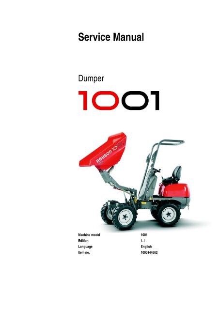
<strong>Service</strong> <strong>Manual</strong><br />
Dumper<br />
Machine model 1001<br />
Edition 1.1<br />
Language English<br />
Item no. 1000144662
Documentation<br />
Description Order no.<br />
Operation manual 1000103795<br />
<strong>Service</strong> manual<br />
1000144662<br />
Spare parts list 1000164057<br />
Legend<br />
Edition Issued<br />
1.0 04/2005<br />
1.1 01/2007<br />
Copyright – 2004 <strong>Neuson</strong> Baumaschinen GmbH, Linz-Leonding<br />
Printed in Austria<br />
All rights reserved<br />
No part of this publication may be reproduced, translated or used in any form or by any means – graphic, electronic<br />
or mechanical including photocopying, recording, taping or information storage or retrieval systems – without prior<br />
permission in writing from <strong>Neuson</strong> Baumaschinen GmbH.<br />
The cover features the machine with possible optional equipment.<br />
<strong>Neuson</strong> Baumaschinen GmbH<br />
Haidfeldstrasse 37<br />
A-4060 Linz-Leonding<br />
Document: SERV-HB 1001 EN<br />
Order no.: 1000144662<br />
Edition: 1.1
Product evolution:<br />
The 1001 dumper was introduced in 2000 under the name LS850. Series production started in 2001. It was renamed 1001 in 2003.<br />
The predecessor to this machine is the LS750 (1002).<br />
Measures taken Model Serial number Modifications<br />
Series introduction LS850 BA000101F Series introduction<br />
Name changed 1001 BB000680 No modification<br />
1001 BB000865 Steering unit modified<br />
1001 BB001108 Articulated joint improved<br />
1001 BB001274 Articulated joint improved<br />
1001 BB001326 Standard colour changed from yellow to red<br />
1001 BB001361 Parking brake fitted with solenoid valve<br />
1001 AB100001H Engine and hydraulic pump modified
Table of contents<br />
Table of contents<br />
Table of contents<br />
Operation<br />
Important information on this service manual .......................................................... 1-1<br />
Identification of warnings and dangers .................................................................... 1-2<br />
Designated use and exemption from liability ........................................................... 1-3<br />
Type labels and component numbers ...................................................................... 1-4<br />
Machine: overview ................................................................................................... 1-6<br />
Operating equipment: overview ............................................................................... 1-7<br />
Operating equipment: legend .................................................................................. 1-8<br />
Maintenance prop .................................................................................................... 1-8<br />
Centre pivot prop ..................................................................................................... 1-9<br />
Specifications<br />
Chassis .................................................................................................................... 2-1<br />
Engine ...................................................................................................................... 2-1<br />
Fuel injection pump ........................................................................................... 2-2<br />
Engine capacities .............................................................................................. 2-2<br />
Engine tightening torques .................................................................................. 2-2<br />
Travelling drive ........................................................................................................ 2-3<br />
Brakes ...................................................................................................................... 2-3<br />
Steering system.........................................................................................................2-3<br />
Work hydraulics ....................................................................................................... 2-3<br />
Loader unit.................................................................................................................2-3<br />
Drive specifications....................................................................................................2-4<br />
Vibration .................................................................................................................. 2-4<br />
Electric system (up to BB001360) ........................................................................... 2-5<br />
Fuse box ............................................................................................................ 2-5<br />
Relays ................................................................................................................ 2-5<br />
Electric system (from AB100001H) .......................................................................... 2-6<br />
Fuse box ............................................................................................................ 2-6<br />
Relays ................................................................................................................ 2-6<br />
Parking brake relay ............................................................................................ 2-7<br />
Tyres ........................................................................................................................ 2-7<br />
Noise levels ............................................................................................................ 2-7<br />
Coolant compound table .......................................................................................... 2-7<br />
General tightening torques ...................................................................................... 2-8<br />
Tightening torques for hydraulic screw connections (dry assembly) ................. 2-8<br />
Tightening torques for high-resistance screw connections .............................. 2-10<br />
Tightening moments for Nordlock lock washers .............................................. 2-11<br />
Dimensions model 1001 ........................................................................................ 2-12<br />
Maintenance<br />
Fluids and lubricants ................................................................................................ 3-1<br />
Maintenance plan (overview) ................................................................................... 3-3<br />
<strong>Service</strong> package ...................................................................................................... 3-6<br />
Introduction .............................................................................................................. 3-6<br />
Fuel system ............................................................................................................. 3-7<br />
Specific safety instructions ................................................................................ 3-7<br />
Refuelling ........................................................................................................... 3-7<br />
Stationary fuel pumps ........................................................................................ 3-8<br />
Diesel fuel specification ..................................................................................... 3-8<br />
Bleeding the fuel system ................................................................................... 3-9<br />
Fuel prefilter with water separator ................................................................... 3-10<br />
Replacing the fuel filter .................................................................................... 3-11<br />
Engine lubrication system ...................................................................................... 3-12<br />
Checking the oil level ....................................................................................... 3-12<br />
Filling up engine oil .......................................................................................... 3-13<br />
SERV-HB 1001 EN - Edition 1.1 * 1001s11IVZ.fm I-1
Table of contents<br />
Changing engine oil ......................................................................................... 3-13<br />
Replacing the engine oil filter cartridge ............................................................ 3-15<br />
Cooling system ...................................................................................................... 3-16<br />
Specific safety instructions .............................................................................. 3-16<br />
Checking/filling up coolant ............................................................................... 3-17<br />
Draining coolant ............................................................................................... 3-18<br />
Air filter ................................................................................................................... 3-19<br />
Weekly check of air filter contamination .......................................................... 3-19<br />
Filter replacement ............................................................................................ 3-20<br />
V-belt ...................................................................................................................... 3-21<br />
Checking V-belt tension ................................................................................... 3-21<br />
Retightening the V-belt .................................................................................... 3-22<br />
Hydraulic system .................................................................................................... 3-23<br />
Specific safety instructions .............................................................................. 3-23<br />
Checking the hydraulic oil level ....................................................................... 3-24<br />
Filling up hydraulic oil ...................................................................................... 3-24<br />
Changing hydraulic oil ..................................................................................... 3-25<br />
Monitoring the hydraulic oil reflux filter ............................................................ 3-25<br />
Replacing the hydraulic oil reflux filter ............................................................. 3-25<br />
Checking hydraulic pressure lines ................................................................... 3-26<br />
Lubrication points ................................................................................................... 3-27<br />
Tyre maintenance .................................................................................................. 3-28<br />
Checks once a day .......................................................................................... 3-28<br />
Checks once a week ........................................................................................ 3-28<br />
Changing wheels .................................................................................................. 3-29<br />
Removing the wheels ...................................................................................... 3-29<br />
Fitting the wheels ............................................................................................. 3-29<br />
Electric system ....................................................................................................... 3-30<br />
Specific safety instructions .............................................................................. 3-30<br />
<strong>Service</strong> and maintenance work at regular intervals ......................................... 3-30<br />
Instructions concerning specific components .................................................. 3-31<br />
Alternator ......................................................................................................... 3-31<br />
Battery ............................................................................................................. 3-32<br />
Battery master switch ............................................................................................. 3-33<br />
General maintenance work .................................................................................... 3-34<br />
Cleaning ........................................................................................................... 3-34<br />
General instructions for all areas of the machine ............................................ 3-34<br />
Screw connections and attachments ............................................................... 3-34<br />
Pivots and hinges ............................................................................................ 3-34<br />
I-2 SERV-HB 1001 EN - Edition 1.1 * 1001s11IVZ.fm
Table of contents<br />
Engine<br />
Engine overview 3TNE74 (up to BB001360) ........................................................... 4-1<br />
Fuel system (up to BB001360) ................................................................................ 4-3<br />
Engine overview 3TNV76-XNSV (from AB100001H) .............................................. 4-4<br />
Fuel system (from AB100001H) .............................................................................. 4-6<br />
Checking and adjusting valve tip clearance ............................................................. 4-7<br />
Tightening order for cylinder head bolts .................................................................. 4-8<br />
Checking the injection nozzles ................................................................................ 4-9<br />
Pressure check .................................................................................................. 4-9<br />
Checking the nozzle jet ............................................................................................ 4-9<br />
Fuel injection time (up to BB001360) ..................................................................... 4-10<br />
Fuel injection time (from AB100001H) ................................................................... 4-11<br />
Adjusting engine revs ............................................................................................ 4-12<br />
Compression .......................................................................................................... 4-12<br />
Checking the coolant thermostat ........................................................................... 4-13<br />
Checking the thermal switch .................................................................................. 4-13<br />
Oil pressure switch ................................................................................................ 4-14<br />
Checking the coolant circuit ................................................................................... 4-14<br />
Engine trouble ....................................................................................................... 4-15<br />
Travelling drive<br />
Variable displacement pump A10VG45DA (up to BB001360) ................................. 5-1<br />
Variable displacement pump: diagram .............................................................. 5-3<br />
Variable displacement pump A10VG28DA (from AB100001H) ............................... 5-4<br />
Variable displacement pump: diagram .............................................................. 5-6<br />
Variable displacement pump: design ................................................................. 5-7<br />
Travelling drive: overview .................................................................................. 5-8<br />
Connecting plate with valves ............................................................................. 5-9<br />
Rear hydraulic motor ............................................................................................. 5-10<br />
Front hydraulic motor ............................................................................................. 5-11<br />
Hydraulic motor: overview ............................................................................... 5-12<br />
Travelling drive: overview ...................................................................................... 5-14<br />
Towing and transporting the machine .................................................................... 5-15<br />
Safety instructions ........................................................................................... 5-15<br />
Towing ............................................................................................................. 5-15<br />
Opening the high-pressure circuit .................................................................... 5-15<br />
Releasing the hydraulic parking brake ............................................................ 5-16<br />
Test instruction ...................................................................................................... 5-17<br />
Pilot pressure check ........................................................................................ 5-17<br />
High pressure check ........................................................................................ 5-18<br />
Brakes<br />
Brake circuit up to serial no. BB001360 ................................................................... 6-1<br />
Brake diagram ................................................................................................... 6-2<br />
Brake circuit from serial no. BB001361 ................................................................... 6-3<br />
Brake diagram ................................................................................................... 6-4<br />
Steering system<br />
Steering circuit ......................................................................................................... 7-1<br />
Steering unit: diagram .............................................................................................. 7-2<br />
Function ............................................................................................................. 7-2<br />
Steering unit connections ........................................................................................ 7-3<br />
Steering unit: overview ............................................................................................ 7-4<br />
Priority valve: overview ...................................................................................... 7-4<br />
Priority valve: legend ......................................................................................... 7-4<br />
Steering unit ...................................................................................................... 7-5<br />
Steering unit: legend .......................................................................................... 7-6<br />
SERV-HB 1001 EN - Edition 1.1 * 1001s11IVZ.fm I-3
Table of contents<br />
Hydraulic system<br />
Control valve connections: overview ........................................................................ 8-1<br />
Test instructions ....................................................................................................... 8-2<br />
Check: work pump pressure .............................................................................. 8-2<br />
Diagram up to serial no. BB001360 ......................................................................... 8-3<br />
Diagram up to serial no. BB001360: legend ............................................................ 8-4<br />
Diagram from serial no. AB100001H ....................................................................... 8-5<br />
Diagram from serial no. AB100001H: legend .......................................................... 8-6<br />
Hydraulics diagram A3 up to serial no. BB001360 .................................................. 8-7<br />
Hydraulics diagram A3 from serial no. AB10001H ................................................... 8-8<br />
Electric system<br />
Ohm's Law (current, voltage, resistance); power ..................................................... 9-1<br />
Measuring equipment, measuring methods ............................................................. 9-1<br />
Relays ...................................................................................................................... 9-2<br />
Use, mode of function ........................................................................................ 9-2<br />
Electric components ................................................................................................. 9-3<br />
Fuse box in instrument panel (up to BB001360) ...................................................... 9-3<br />
Relays ................................................................................................................ 9-3<br />
Instrument panel up to BB001360: overview ........................................................... 9-4<br />
Fuse box in instrument panel (from AB100001H) .................................................... 9-5<br />
Relays ................................................................................................................ 9-5<br />
Instrument panel (from AB100001H): overview ....................................................... 9-6<br />
Wiring diagram up to serial no. BB001360: legend .................................................. 9-8<br />
Wiring diagram version 1 A4 up to serial no. BB001360 ......................................... 9-9<br />
Wiring diagram from serial no. AB100001H: legend .............................................. 9-10<br />
Wiring diagram version 1 A4 from serial no. AB100001H ...................................... 9-11<br />
Main wiring harness from AB100001H: legend ...................................................... 9-12<br />
............................................................................................................................... 9-12<br />
Main wiring harness from AB100001H .................................................................. 9-13<br />
Engine wiring harness from AB100001H: legend .................................................. 9-14<br />
Engine wiring harness from AB100001H ............................................................... 9-15<br />
Wiring diagram A3 up to serial no. BB001360: legend .......................................... 9-18<br />
Wiring diagram A3 up to serial no. BB001360 ....................................................... 9-19<br />
Wiring diagram A3 from serial no. AB100001H: legend ........................................ 9-20<br />
Wiring diagram A3 from serial no. AB100001H ..................................................... 9-21<br />
Main wiring harness from AB100001H: legend ...................................................... 9-22<br />
Main wiring harness from AB100001H .................................................................. 9-23<br />
Engine wiring harness from AB100001H: legend .................................................. 9-24<br />
Engine wiring harness from AB100001H ............................................................... 9-25<br />
I-4 SERV-HB 1001 EN - Edition 1.1 * 1001s11IVZ.fm
Operation
1 Operation<br />
Operation<br />
1.1 Important information on this service manual<br />
Operation<br />
This service manual contains important information on how to service your machine safely,<br />
correctly and economically. Therefore, it aims not only at new operators, but it also serves<br />
as a reference for experienced ones. It helps to avoid dangerous situations and reduce<br />
repair costs and downtimes. Furthermore, the reliability and the service life of the machine<br />
will be increased by following the instructions in the service manual.<br />
Careful and prudent working is the best way to avoid accidents!<br />
Operational safety and readiness of the machine do not only depend on your skill, but also<br />
on maintenance and service of the machine.<br />
Insist on using original spare parts when carrying out maintenance and repair work. This<br />
ensures operational safety and readiness of your machine, and maintains its value.<br />
Your <strong>Neuson</strong> dealer will be pleased to answer any further questions regarding the<br />
machine or the service manual.<br />
Abbreviations/symbols<br />
• This symbol stands for a list<br />
Subdivision within lists or an activity. Follow the steps in the recommended sequence<br />
☞This symbol requires you to carry out the activity described<br />
➥Description of the effects or results of an activity<br />
n. s. = not shown<br />
“Option” = optional equipment<br />
Stated whenever controls or other components of the machine are installed as an option.<br />
A combination of digits, or a combination of digits and letters, e.g. 40/18 or 40/A used for<br />
identifying the control elements, means:<br />
Figure no. 40/control element no. 18 or position A in figure no. 40<br />
Figures carry no numbers if they are placed to the left of the text.<br />
SERV-HB 1001 EN – Edition 1.1 * 1001s110.fm 1-1
Operation<br />
1.2 Identification of warnings and dangers<br />
Important indications regarding the safety of the staff and the machine are indicated in this<br />
operation manual with the following terms and symbols:<br />
Danger!<br />
Failure to observe the instructions identified by this symbol may result in<br />
personal injury or death for the operator or other persons.<br />
☞Measures for avoiding danger<br />
Caution!<br />
Failure to observe the instructions identified by this symbol may result in<br />
damage to the machine.<br />
☞Measures for avoiding danger for the machine<br />
Important!<br />
This symbol identifies instructions for a more efficient and economical use of the<br />
machine.<br />
Environment!<br />
Failure to observe the instructions identified by this symbol may result in damage to the<br />
environment. The environment is in danger if environmentally hazardous material (e.g.<br />
waste oil) is not subject to proper use or disposal.<br />
1-2 SERV-HB 1001 EN – Edition 1.1 * 1001s110.fm
1.3 Designated use and exemption from liability<br />
The machine is intended for:<br />
transporting the usual bulk material and concrete on construction sites<br />
Operation<br />
Every other application is regarded as not designated for the use of the machine.<br />
<strong>Neuson</strong> Baumashinen GmbH will not be liable for damage resulting from use other<br />
than mentioned above. The user alone will bear the risk.<br />
Designated use also includes observing the instructions set forth in the operation<br />
manual and observing the maintenance and service conditions.<br />
The safety of the machine can be negatively affected by carrying out machine modifications<br />
without proper authority and by using spare parts, equipment, attachments and<br />
optional equipment which have not been checked and released by <strong>Neuson</strong><br />
Baumaschinen GmbH. <strong>Neuson</strong> Baumaschinen GmbH will not be liable for damage<br />
resulting from this<br />
<strong>Neuson</strong> Baumaschinen GmbH shall not be liable for personal injury and/or damage to<br />
property caused by failure to observe the safety instructions and the operation manual,<br />
and by the negligence of the duty to exercise due care when:<br />
handling<br />
operating<br />
servicing and carrying out maintenance work and<br />
repairing the machine. This is also applicable in those cases in which special<br />
attention has not been drawn to the duty to exercise due care, in the safety instructions<br />
as well as in the operation and maintenance manuals (machine/engine).<br />
Read and understand the operation manual before starting up, servicing or repairing<br />
the machine. Observe the safety instructions!<br />
SERV-HB 1001 EN – Edition 1.1 * 1001s110.fm 1-3
Operation<br />
1.4 Type labels and component numbers<br />
Fig. 1: Type label<br />
Fig. 2: Diesel engine number<br />
Fig. 3: Hydraulic pump type label<br />
Serial number<br />
The serial number is stamped on the machine chassis next to the right-hand side front<br />
tyre. It is also located on the type label.<br />
The type label is also located at the front right, on the chassis next to the tyre.<br />
Type label information<br />
Machine model: 1001<br />
EEC no.: ----------------<br />
Serial no.: BB 000000<br />
Gross weight: ----------<br />
Front gross axle weight rating: 1165 KG<br />
Rear gross axle weight rating: 1000 KG<br />
Year of construction: 2004<br />
Output: 12.1 kW<br />
Dead weight: ----------------<br />
Other information – see chapter 2 Specifications on page 2-1<br />
Engine number<br />
The type label (arrow) is located on the cylinder-head cover (engine).<br />
Example: Yanmar 46557<br />
Hydraulic pump number<br />
The type label (arrow) is located on the hydraulic pump housing.<br />
1-4 SERV-HB 1001 EN – Edition 1.1 * 1001s110.fm
Fig. 4: Hydraulic pump type label<br />
Fig. 5: Rollbar type label<br />
Fig. 6: Travelling drive type label<br />
Spool number<br />
The type label (arrow) is located on the spool housing<br />
Rollbar number<br />
The type label (arrow) is located on the rollbar.<br />
Hydraulic motor numbers<br />
The type label (arrow) is located on the lower side of the hydraulic motor.<br />
Operation<br />
SERV-HB 1001 EN – Edition 1.1 * 1001s110.fm 1-5
Operation<br />
1.5 Machine: overview<br />
5<br />
8<br />
1<br />
Fig. 7: Machine outside views<br />
6<br />
13<br />
4<br />
9<br />
1 Rear chassis<br />
2 Front chassis<br />
3 Lift frame<br />
4 Articulated joint<br />
5 Seat<br />
6 Control stand<br />
7 Tilt console<br />
8 Engine cover<br />
9 Parallel lift<br />
10 Skip<br />
11 Lift ram<br />
12 Tilt ram<br />
13 Steering ram<br />
1-6 SERV-HB 1001 EN – Edition 1.1 * 1001s110.fm<br />
12<br />
10<br />
7<br />
3<br />
11<br />
2
1.6 Operating equipment: overview<br />
14<br />
14<br />
7<br />
19<br />
17 18<br />
8<br />
6<br />
14<br />
15<br />
Operation<br />
SERV-HB 1001 EN – Edition 1.1 * 1001s110.fm 1-7<br />
20<br />
2<br />
9<br />
1<br />
16<br />
3<br />
10<br />
4<br />
11<br />
12<br />
13<br />
14<br />
2<br />
5
Operation<br />
1.7 Operating equipment: legend<br />
1.8 Maintenance prop<br />
A<br />
Pos. Description<br />
1 Accelerator pedal<br />
2 <strong>Service</strong> brake<br />
3 Ignition lock<br />
4 Forwards-reverse control<br />
5 Horn<br />
6 Instrument panel<br />
7 Preheating telltale<br />
8 Hydraulic oil filter telltale<br />
9 Alternator charge function telltale<br />
10 Parking brake telltale<br />
11 Engine oil pressure telltale<br />
12 Engine temperature telltale<br />
13 Turn indicators<br />
14 Not assigned<br />
15 Hour meter<br />
16 Parking brake<br />
17 Lever for tilting/lowering the skip<br />
18 Lever for raising/lowering the skip<br />
19 Bar for horizontal seat adjustment<br />
20 Fuel level indicator<br />
Fig. 8: Maintenance prop<br />
C<br />
B<br />
Danger!<br />
Fold down the red maintenance prop before you carry out maintenance work<br />
with the lift frame raised.<br />
The maintenance prop shows downwards vertically and is automatically positioned in a<br />
socket in case the lift frame should be lowered.<br />
Proceed as follows:<br />
☞Remove the spring plug from pin B<br />
☞Remove the pin from guide C<br />
☞Fold down maintenance prop A<br />
Important!<br />
Fold back the maintenance prop in the reverse order once maintenance work is<br />
over.<br />
1-8 SERV-HB 1001 EN – Edition 1.1 * 1001s110.fm
1.9 Centre pivot prop<br />
B<br />
Fig. 9: Centre pivot prop<br />
A<br />
Fig. 10: Centre pivot prop<br />
C<br />
A<br />
Danger!<br />
Operation<br />
Secure the steering ram with the red centre pivot prop when crane handling<br />
the machine.<br />
The centre pivot prop secures the steering ram to prevent steering movements (via the<br />
articulated joint) when crane handling the dumper.<br />
Proceed as follows:<br />
☞Remove the spring plug from pin B<br />
☞Rotate centre pivot prop A towards pin C<br />
☞Secure centre pivot prop A with the spring plug on pin C<br />
Important!<br />
Mount the centre pivot prop back onto pin B as soon as the machine is taken into<br />
service again.<br />
SERV-HB 1001 EN – Edition 1.1 * 1001s110.fm 1-9
Operation<br />
1-10 SERV-HB 1001 EN – Edition 1.1 * 1001s110.fm
Specifications
2 Specifications<br />
2.1 Chassis<br />
2.2 Engine<br />
Specifications<br />
Sturdy steel sheet chassis, rubber-mounted engine<br />
Specifications<br />
Engine Up to BB001360 From AB100001H<br />
Product Yanmar diesel engine Yanmar diesel engine<br />
Model 3TNE74-NSR3 3TNV76-XNSV<br />
Design Water-cooled 4 stroke diesel engine Water-cooled 4-stroke diesel engine, EPA2<br />
No. of cylinders 3 3<br />
Fuel injection system Direct injection Indirect injection<br />
Aspiration Natural aspiration Natural aspiration<br />
Cooling system Water-cooled Water-cooled/aspirating fan<br />
Lubrication system Force-feed lubrication with trochoidal pump Force-feed lubrication with trochoidal pump<br />
Displacement 1006 cm³ 1116 cm³<br />
Nominal bore and stroke 74 x 78 mm 76 x 82 mm<br />
Output 12.1 kW at 2200 rpm 17 kW<br />
Max. torque 63 Nm 65.8 Nm at 1600 rpm<br />
Max. engine speed without load 2000 rpm 3000 rpm<br />
Idling speed ~860 rpm 1100 +/- 25 rpm<br />
Valve tip clearance (intake =<br />
outlet)<br />
0.15 – 0.25 mm (cold) 0.15 – 0.25 mm (cold)<br />
Compression 23.5 : 1<br />
Compression: specified value 35 +/- 1 bar at 250 rpm 35 bar at 250 rpm<br />
Compression: threshold value 28 bar at 250 rpm<br />
Engine oil pressure under full<br />
load<br />
3 – 4 bar 0.3 – 0.45 bar<br />
Pressure switch for engine oil<br />
pump<br />
0.5 +/- 0.1 bar 0.5 +/- 0.1 bar<br />
Thermostat opens at 69.5 – 72.5 °C 69.5 – 72.5 °C<br />
Thermal switch 107 – 113 °C 107 – 113 °C<br />
Firing order 1 – 3 – 2 1 – 3 – 2<br />
Direction of rotation<br />
Counterclockwise<br />
(as seen from the flywheel)<br />
Counterclockwise<br />
(as seen from the flywheel)<br />
Starting aid<br />
Glow plug (preheating time 10 – 15 seconds)<br />
Glow plugs (preheating time 4 seconds)<br />
Max. inclined position (engine<br />
no longer supplied with oil):<br />
25°/45% in all directions<br />
25°/46 % in all directions<br />
30°/58 % for 3 minutes Observe the<br />
machine's climbing ability (30°/58 %)!<br />
Specific fuel consumption 272 g/kWh<br />
Exhaust values according to 97/68/EC EPA Tier II<br />
SERV-HB 1001 EN – Edition 1.1 * 1001s210.fm 2-1
Specifications<br />
Fuel injection pump<br />
Engine capacities<br />
Engine tightening torques<br />
Model<br />
Design In-line fuel injection pump<br />
Injection pressure 120 +10 bar<br />
Revs control Mechanical<br />
Injection time 16°<br />
Lubrication system Forced feed lubrication<br />
Capacities Up to BB001360 From AB100001H<br />
Fuel tank 15 l 15 l<br />
Engine oil (max./effect.) 2.25 l/1.0 l 2.25 l/1.0 l<br />
Coolant (without radiator) 0.9 l 0.9 l<br />
Radiator 3.1 l 1.2 l<br />
Expansion tank 0.84 l 0.5 l<br />
Overview of capacities: – see Fluids and lubricants on page 3-1<br />
Tightening torques Up to BB001360 From AB100001H<br />
Cylinder-head bolt 60.0 – 65.0 (M9x1.25) 53.9 – 57.9 Nm (M9x1.25)<br />
Connecting rod bearing<br />
screw<br />
23.0 – 28.0 (M7x1) 22.6 – 27.5 Nm (M7x1)<br />
Main bearing screw 80.0 – 85.0 (M10x1.25) 75.5 – 81.5 Nm (M10x1.25)<br />
Flywheel screw 80.0 – 90.0 (M10x1.25) 80.4 – 86.4 Nm (M10x1.25)<br />
2-2 SERV-HB 1001 EN – Edition 1.1 * 1001s210.fm
2.3 Travelling drive<br />
2.4 Brakes<br />
2.5 Steering system<br />
2.6 Work hydraulics<br />
2.7 Loader unit<br />
Variable displacement<br />
pump<br />
Design Axial piston pump<br />
Up to BB001360 From AB100001H<br />
Specifications<br />
Axial piston variable displacement<br />
pump<br />
Displacement 0 – 45 cm³/rev 0 – 28 cm³/rev<br />
Flow rate 99 l/min 54.6 kW<br />
Max. service pressure 360 bar 350 bar<br />
Boost pump (integrated in variable displacement pump)<br />
Design Gear pump Gear pump<br />
Displacement 11.6 cm³/rev 6.1 cm³/rev<br />
Flow rate<br />
25 l/min<br />
Charging/boost pressure 20 bar 25 bar<br />
<strong>Service</strong> brake/<br />
parking brake<br />
Up to<br />
BB001360<br />
From AB100001H<br />
Design Hydrostatic Pedal-operated hydrostatic drive brake<br />
Location<br />
Rear hydraulic motors<br />
Effect<br />
Hydraulic parking brake for auxiliary brake and parking brake with<br />
hand brake valve control<br />
Steering system Model 1001<br />
Design<br />
Hydrostatic chassis articulation steering with<br />
emergency steering features.<br />
Steering mode<br />
Chassis articulation steering<br />
Work hydraulics<br />
A10VG45 DA1D2<br />
up to BB001360<br />
A10VG28 DA1D2<br />
from AB100001H<br />
Hydraulic pump displacement 8.3 cm³/rev 28 cm³/rev<br />
Hydraulic pump flow rate 18 l/min 109 l/min<br />
Control valve 2 sections 2 sections<br />
Max. service pressure 170 bar 350 bar<br />
Secondary pressure limiting for steering<br />
ram<br />
150 bar 150 bar<br />
Hydraulic oil cooler Standard Standard<br />
Hydraulic tank capacity 20 l 20 l<br />
Loader unit Model 1001<br />
415 l struck<br />
Skip capacity<br />
525 l heaped<br />
275 l liquid capacity<br />
Payload 1000 kg<br />
SERV-HB 1001 EN – Edition 1.1 * 1001s210.fm 2-3
Specifications<br />
2.8 Drive specifications<br />
2.9 Vibration<br />
Steering system<br />
Drive speed<br />
Articulation<br />
Oscillation<br />
Outside turning radius<br />
Hill climbing ability<br />
Safe authorised inclination<br />
Max. authorised lateral inclination<br />
with narrow tyres<br />
Vibration<br />
Effective acceleration value for the<br />
upper extremities of the body *<br />
Effective acceleration value for the<br />
body *<br />
Model 1001<br />
0 – 14 kph<br />
+/- 33°<br />
+/- 15°<br />
3200 mm<br />
* Measured according to 2002/44/EC. Machine and attachment operation and maintenance as per operation manual.<br />
2-4 SERV-HB 1001 EN – Edition 1.1 * 1001s210.fm<br />
45 %<br />
20 % in all directions<br />
10 %<br />
< Trigger value<br />
< Trigger value
2.10 Electric system (up to BB001360)<br />
Fuse box<br />
Fig. 1: Fuse box<br />
Relays<br />
K6<br />
K8<br />
K7<br />
Fig. 2: Relays<br />
Electric system<br />
Alternator 12 V 20 A<br />
Starter 12 V 1.2 kW<br />
Battery 12 V 74 Ah<br />
Specifications<br />
Driving direction Fuse no. Rated current (A) Protected circuit<br />
1<br />
30 A<br />
– Cutoff solenoid, cutoff solenoid time lag<br />
relay<br />
2 7.5 A – Horn<br />
3 7.5 A – Alternator governor<br />
4 7.5 A – Solenoid valve pump<br />
5 7.5 A – Light switch<br />
6 – Not assigned<br />
7 – Not assigned<br />
8 7.5 A – Telltales<br />
9 – Not assigned<br />
10 – Not assigned<br />
11 – Not assigned<br />
The relays are located in the relay box under the control stand, next to the swivelling console<br />
K9<br />
A3 Switching relay no. Protected circuit<br />
K30<br />
F12<br />
K7.1<br />
K 6 – Preheating time lag relay<br />
K 8 – Cutoff solenoid time lag relay<br />
K 7 – High current relay – start<br />
K 9 – Cutoff solenoid switching relay<br />
K 30 – Relay for parking brake warning buzzer<br />
K 7.1 – Start interlock relay<br />
A3 – Regulator<br />
F12 – Main fuse<br />
SERV-HB 1001 EN – Edition 1.1 * 1001s210.fm 2-5
Specifications<br />
2.11 Electric system (from AB100001H)<br />
Fuse box The fuse box is located on the right-hand side of the machine under the engine cover.<br />
F10 F9 F8 F7<br />
Fig. 3: Fuse box<br />
Relays<br />
K6<br />
F1<br />
F2<br />
Fig. 4: Relays<br />
F6<br />
K9 K10 K30<br />
F5<br />
K34 K33 K32<br />
F4<br />
V2<br />
F3<br />
K8<br />
Electric system<br />
Alternator 12 V 20 A<br />
Starter 12 V 1.2 kW<br />
Battery 12 V 45 Ah<br />
Fuse no. Rated current (A) Protected circuit<br />
F 3 10 A<br />
– Cutoff solenoid, cutoff solenoid time lag<br />
relay<br />
F 4 15 A – Drive solenoid valves<br />
F 5 10 A – Horn, parking brake, brake lights<br />
F 6 15 A – Turn indicators<br />
F 7 15 A – High beam<br />
F 8 10 A – Low beam<br />
F 9 10 A – Position light<br />
F10 10 A – Hazard warning system<br />
The relays are located in the relay box under the control stand, next to the swivelling console<br />
Switching relay no. Protected circuit<br />
K 6 – Preheating time lag relay<br />
K 8 – Cutoff solenoid time lag relay<br />
K 9 – Cutoff solenoid switching relay<br />
K 10 – Turn indicator relay<br />
K 30 – Parking brake relay<br />
K 32 – Start interlock relay<br />
K 33 – Low beam relay<br />
K 34 – High beam relay<br />
V2 – Diodes<br />
F 1, 2 – Main fuses<br />
2-6 SERV-HB 1001 EN – Edition 1.1 * 1001s210.fm
Parking brake relay<br />
2.12 Tyres<br />
2.13 Noise levels<br />
2.14 Coolant compound table<br />
Fig. 5: Parking brake relay<br />
Important!<br />
Specifications<br />
Tyre pressure<br />
Tyre size<br />
Front Rear Wheel offset<br />
10.00/7.5x15 3 bar 3 bar 20<br />
6.0 x 16 (optional narrow tyres) 3 bar 3 bar 25<br />
Sound power level Up to BB001360 From AB 100001H<br />
Sound power level (LWA) 102 dB (A) 101 dB (A)<br />
Measurement of sound power level according to EC Directive 2000/14 EC. Noise<br />
level at the driver's ear measured according to EC Directives 84/532/EEC, 89/514/<br />
EEC and 95/27/EEC. Measurements carried out on asphalted surface.<br />
Outside tempera-<br />
Coolant<br />
ture Water Anticorrosion agent Antifreeze agent<br />
Up to °C<br />
% by<br />
volume<br />
cm³/l % by volume % by volume<br />
4 99<br />
–<br />
-10 79 20<br />
-20 65 10 1<br />
34<br />
-25 59 40<br />
-30 55 44<br />
SERV-HB 1001 EN – Edition 1.1 * 1001s210.fm 2-7
Specifications<br />
2.15 General tightening torques<br />
Tightening torques for hydraulic screw connections (dry assembly)<br />
Metric hose fittings for hydraulic applications (light execution, DKOL)<br />
Nominal ø Outer ø Thread<br />
Width across<br />
flats<br />
Tightening<br />
torque<br />
05 6L M12X1.5 W/F 14 15 Nm<br />
06 8L M14X1.5 W/F 17 20 Nm<br />
08 10L M16X1.5 W/F 19 40 Nm<br />
10 12L M18X1.5 W/F 22 50 Nm<br />
12 15L M22X1.5 W/F 27 75 Nm<br />
16 18L M26X1.5 W/F 32 85 Nm<br />
20 22L M30X2 W/F 36 100 Nm<br />
25 28L M36X2 W/F 41 180 Nm<br />
32 35L M45X2 W/F 55 220 Nm<br />
Galvanised and dry surface (O-ring slightly oiled). Torque tolerance: -10 %<br />
Values determined empirically and to be applied as approximate figures.<br />
Metric hose fittings for hydraulic applications (heavy execution, DKOL)<br />
Nominal ø Outer ø Thread<br />
Width across<br />
flats<br />
Tightening<br />
torque<br />
05 8S M16X1.5 W/F 19 40 Nm<br />
06 10S M18X1.5 W/F 22 50 Nm<br />
08 12S M20X1.5 W/F 24 60 Nm<br />
10 14S M22X1.5 W/F 27 75 Nm<br />
12 16S M24X1.5 W/F 30 90 Nm<br />
16 20S M30X2 W/F 36 100 Nm<br />
20 25S M36X2 W/F 41 180 Nm<br />
25 30S M42X2 W/F 50 270 Nm<br />
32 38S M52X2 W/F 60 400 Nm<br />
Galvanised and dry surface (O-ring slightly oiled). Torque tolerance: -10 %<br />
Values determined empirically and to be applied as approximate figures.<br />
Screw connections with various seals for hydraulic applications (light execution)<br />
Straight pipe fitting with thread and Non-return<br />
Thread<br />
Sealing<br />
washer<br />
screwed plug<br />
Elastic<br />
seal<br />
O-ring<br />
valve with<br />
elastic<br />
seal<br />
Identification<br />
aid outside Ø<br />
M10X1.0 9 Nm 18 Nm 15 Nm 18 Nm 10 mm<br />
M12X1.5 20 Nm 25 Nm 25 Nm 25 Nm 12 mm<br />
M14X1.5 35 Nm 45 Nm 35 Nm 35 Nm 14 mm<br />
M16X1.5 45 Nm 55 Nm 40 Nm 50 Nm 16 mm<br />
M18X1.5 55 Nm 70 Nm 45 Nm 70 Nm 18 mm<br />
M22X1.5 65 Nm 125 Nm 60 Nm 125 Nm 22 mm<br />
M27X2.0 90 Nm 180 Nm 100 Nm 145 Nm 27 mm<br />
M33X2.0 150 Nm 310 Nm 160 Nm 210 Nm 33 mm<br />
2-8 SERV-HB 1001 EN – Edition 1.1 * 1001s210.fm
Torque tolerance: – 10 %; countermaterial: steel/aluminium<br />
Torque tolerance: – 10 %; countermaterial: steel/aluminium<br />
Specifications<br />
Screw connections with various seals for hydraulic applications (light execution)<br />
M42X2.0 240 Nm 450 Nm 210 Nm 360 Nm 42 mm<br />
M48X2.0 290 Nm 540 Nm 260 Nm 540 Nm 48 mm<br />
G1/8A 9 Nm 18 Nm 15 Nm 18 Nm 9.73 mm<br />
G1/4A 35 Nm 35 Nm 30 Nm 35 Nm 13.16 mm<br />
G3/8A 45 Nm 70 Nm 45 Nm 50 Nm 16.66 mm<br />
G1/2A 65 Nm 90 Nm 55 Nm 65 Nm 20.96 mm<br />
G3/4A 90 Nm 180 Nm 100 Nm 140 Nm 26.44 mm<br />
G1A 150 Nm 310 Nm 160 Nm 190 Nm 33.25 mm<br />
G1 1/4A 240 Nm 450 Nm 210 Nm 360 Nm 41.91 mm<br />
G1 1/2A 290 Nm 540 Nm 260 Nm 540 Nm 47.80 mm<br />
Screw connections with various seals for hydraulic applications (heavy execution)<br />
Straight pipe fitting with thread and Non-return<br />
Thread<br />
Sealing<br />
washer<br />
screwed plug<br />
Elastic<br />
seal<br />
O-ring<br />
valve with<br />
elastic<br />
seal<br />
Identification<br />
aid outside Ø<br />
M12X1.5 20 Nm 35 Nm 35 Nm 35 Nm 12 mm<br />
M14X1.5 35 Nm 55 Nm 45 Nm 45 Nm 14 mm<br />
M16X1.5 45 Nm 70 Nm 55 Nm 55 Nm 16 mm<br />
M18X1.5 55 Nm 90 Nm 70 Nm 70 Nm 18 mm<br />
M20X1.5 55 Nm 125 Nm 80 Nm 100 Nm 20 mm<br />
M22X1.5 65 Nm 135 Nm 100 Nm 125 Nm 22 mm<br />
M27X2.0 90 Nm 180 Nm 170 Nm 135 Nm 27 mm<br />
M33X2.0 150 Nm 310 Nm 310 Nm 210 Nm 33 mm<br />
M42X2.0 240 Nm 450 Nm 330 Nm 360 Nm 42 mm<br />
M48X2.0 290 Nm 540 Nm 420 Nm 540 Nm 48 mm<br />
G1/8A 35 Nm 55 Nm 45 Nm 45 Nm 13.16 mm<br />
G1/4A 45 Nm 80 Nm 60 Nm 60 Nm 16.66 mm<br />
G3/8A 65 Nm 115 Nm 75 Nm 100 Nm 20.96 mm<br />
G1/2A 90 Nm 180 Nm 170 Nm 145 Nm 26.44 mm<br />
G3/4A 150 Nm 310 Nm 310 Nm 260 Nm 33.25 mm<br />
G1A 240 Nm 450 Nm 330 Nm 360 Nm 41.91 mm<br />
G1 1/4A 290 Nm 540 Nm 420 Nm 540 Nm 47.80 mm<br />
SERV-HB 1001 EN – Edition 1.1 * 1001s210.fm 2-9
Specifications<br />
Tightening torques for high-resistance screw connections<br />
With coarse-pitch thread<br />
Screws according to DIN 912, DIN Screws according to<br />
Thread<br />
931, DIN 933 etc.<br />
DIN 7984<br />
8.8 10.9 12.9 8.8 10.9<br />
M5 5.5 Nm 8 Nm 10 Nm 5 Nm 7 Nm<br />
M6 10 Nm 14 Nm 17 Nm 8.5 Nm 12 Nm<br />
M8 25 Nm 35 Nm 42 Nm 20 Nm 30 Nm<br />
M10 45 Nm 65 Nm 80 Nm 40 Nm 59 Nm<br />
M12 87 Nm 110 Nm 147 Nm 69 Nm 100 Nm<br />
M14 135 Nm 180 Nm 230 Nm 110 Nm 160 Nm<br />
M16 210 Nm 275 Nm 350 Nm 170 Nm 250 Nm<br />
M18 280 Nm 410 Nm 480 Nm 245 Nm 345 Nm<br />
M20 410 Nm 570 Nm 690 Nm 340 Nm 490 Nm<br />
M22 550 Nm 780 Nm 930 Nm 460 Nm 660 Nm<br />
M24 710 Nm 1000 Nm 1190 Nm 590 Nm 840 Nm<br />
M27 1040 Nm 1480 Nm 1770 Nm 870 Nm 1250 Nm<br />
M30 1420 Nm 2010 Nm 2400 Nm 1200 Nm 1700 Nm<br />
DIN 912 – hexagon socket head cap screw; DIN 931/DIN 933 – hexagon head screw with/without shaft;<br />
DIN 7984 – hexagon socket head cap screw with short head<br />
All values subject to a friction coefficient of µ = 0.12 and are to be used as approximate figures.<br />
With fine-pitch thread<br />
Screws according to DIN 912, DIN Screws according to<br />
Thread<br />
931, DIN 933 etc.<br />
DIN 7984<br />
8.8 10.9 12.9 8.8 10.9<br />
M8X1.0 25 Nm 37 Nm 43 Nm 22 Nm 32 Nm<br />
M10X1.0 50 Nm 75 Nm 88 Nm 43 Nm 65 Nm<br />
M10X1.25 49 Nm 71 Nm 83 Nm 42 Nm 62 Nm<br />
M12X1.25 87 Nm 130 Nm 150 Nm 75 Nm 110 Nm<br />
M12X1.5 83 Nm 125 Nm 145 Nm 72 Nm 105 Nm<br />
M14X1.5 135 Nm 200 Nm 235 Nm 120 Nm 175 Nm<br />
M16X1.5 210 Nm 310 Nm 360 Nm 180 Nm 265 Nm<br />
M18X1.5 315 Nm 450 Nm 530 Nm 270 Nm 385 Nm<br />
M20X1.5 440 Nm 630 Nm 730 Nm 375 Nm 530 Nm<br />
M22X1.5 590 Nm 840 Nm 980 Nm 500 Nm 710 Nm<br />
M24X2.0 740 Nm 1070 Nm 1250 Nm 630 Nm 900 Nm<br />
M27X2.0 1100 Nm 1550 Nm 1800 Nm 920 Nm 1300 Nm<br />
M30X2.0 1500 Nm 2150 Nm 2500 Nm 1300 Nm 1850 Nm<br />
DIN 912 – hexagon socket head cap screw; DIN 931/DIN 933 – hexagon head screw with/without shaft;<br />
DIN 7984 – hexagon socket head cap screw with short head<br />
All values subject to a friction coefficient of µ = 0.12 and are to be used as approximate figures.<br />
2-10 SERV-HB 1001 EN – Edition 1.1 * 1001s210.fm
Tightening moments for Nordlock lock washers<br />
Fig. 6: Nordlock dimensions<br />
Fig. 7: Nordlock<br />
Specifications<br />
Standard dimensions<br />
Thread d (mm) D (mm) T (mm) Mv (Nm)<br />
M3 3.2 7.0 1.8 1.5<br />
M4 4.3 9.0 1.8 3.5<br />
M5 5.2 9.0 1.8 7.2<br />
M6 6.5 10.8 1.8 12<br />
M8 8.2 13.5 2.6 30<br />
M10 10.3 16.6 2.6 59<br />
M12 13.0 19.5 2.6 103<br />
M14 14.5 23.0 3.7 160<br />
M16 17.0 25.4 3.7 250<br />
M18 19.5 29.0 3.7 350<br />
M20 21.0 30.7 3.7 490<br />
M22 22.9 34.5 3.7 660<br />
M24 26.0 39.0 3.7 850<br />
M27 28.5 42.0 4.6 1220<br />
M30 30.5 47.0 4.6 1600<br />
M33 33.5 48.5 4.6 2200<br />
M36 36.6 56.0 4.6 2900<br />
M39 39.5 58.5 4.6 3800<br />
Dimensions with larger outside diameters (oblong bores)<br />
Thread d (mm) D (mm) T (mm) Mv (Nm)<br />
M6 6.5 13.5 2.6 13<br />
M8 8.6 16.6 2.6 32<br />
M10 10.3 21.0 2.6 64<br />
M12 13.0 25.4 3.7 110<br />
M16 17.0 30.7 4.0 260<br />
SERV-HB 1001 EN – Edition 1.1 * 1001s210.fm 2-11
Specifications<br />
2.16 Dimensions model 1001<br />
Fig. 8: Machine dimensions (model 1001)<br />
Main data<br />
Dead weight<br />
Overall height<br />
Overall height with rollbar folded down<br />
Overall height without rollbar<br />
Overall width<br />
Overall width (narrow version)<br />
Ground clearance<br />
Wheelbase<br />
Outside turning radius<br />
Model 1001<br />
1165 kg<br />
2580 mm<br />
2080 mm<br />
1850 mm<br />
1180 mm<br />
990 mm<br />
270 mm<br />
1500 mm<br />
3200 mm<br />
2-12 SERV-HB 1001 EN – Edition 1.1 * 1001s210.fm
Maintenance
3 Maintenance<br />
3.1 Fluids and lubricants<br />
Component/<br />
application<br />
Diesel engine Engine oil<br />
Hydraulic oil tank<br />
Maintenance<br />
Engine/machine<br />
fluid<br />
Hydraulic oil HVLP46 3<br />
Biodegradable oil 4<br />
Specification<br />
API CD, CF, CF-4, CI-4<br />
ACEA: E3, E4, E5 (SAE 10W40) 2<br />
PANOLIN HLP Synth 46<br />
FINA BIOHYDRAN SE 46<br />
BP BIOHYD SE-46<br />
Season/<br />
temperature<br />
- 20 °C<br />
+40 °C<br />
Maintenance<br />
Capacities 1<br />
SERV-HB 1001 EN – Edition 1.1 * 1001s310.fm 3-1<br />
5.8 l<br />
Year-round 25 l<br />
Grease nipples Multipurpose grease 5 FINA Energrease L21 M Year-round As required<br />
Battery terminals Acid-proof grease 6 FINA Marson L2 Year-round As required<br />
Fuel tank Diesel fuel<br />
Radiator Coolant<br />
2-D ASTM D975 – 94 (USA)<br />
1-D ASTM D975 – 94 (USA)<br />
EN 590 : 96 (EU)<br />
ISO 8217 DMX (International)<br />
BS 2869 – A1 (GB) Summer or winter<br />
diesel depending<br />
BS 2869 – A2 (GB)<br />
on outside temperatures<br />
Soft water + antifreeze ASTM D4985<br />
Distilled water + antifreeze ASTM<br />
D4985<br />
1. The capacities indicated are approximative values; the oil level check alone is relevant for the correct oil level<br />
Capacities indicated are no system fills<br />
2. According to DIN 51511<br />
3. According to DIN 51524 section 3<br />
4. Hydraulic ester oils (HEES)<br />
5. KF2K-25 according to DIN 51502 multipurpose lithium grease with MoS² additive<br />
6. Standard acid-proof grease<br />
15 l<br />
Year-round 4 l
Maintenance<br />
Oil grades for the diesel engine, depending on temperature<br />
Engine oil grade Ambient temperature (C°)<br />
°C -20 -15 -10 -5 0 5 10 15 20 25 30 35 40<br />
API CD, CF, CF-4,<br />
CI-4<br />
ACEA: E3, E4, E5<br />
SAE 10W<br />
SAE 20W<br />
SAE 10W-30<br />
SAE 10W-40<br />
SAE 15W-40<br />
SAE 20<br />
SAE 30<br />
SAE 40<br />
°F -4 5 14 23 32 41 50 59 68 77 86 95 104<br />
3-2 SERV-HB 1001 EN – Edition 1.1 * 1001s310.fm
Maintenance<br />
Maintenance plan/service hours (s/h)<br />
3.2 Maintenance plan (overview)<br />
Authorised<br />
workshop<br />
Every 1000 s/h<br />
once a year<br />
Every 500 s/h<br />
Every 50 s/h<br />
Maintenance work<br />
( once a day)<br />
Work description<br />
Customer<br />
For service and maintenance work on the attachment, please refer to the operation and maintenance manual of the attachment<br />
manufacturer as well.<br />
Fluid and filter changes ( ):<br />
Carry out the following oil and filter changes (check oil levels after test run):<br />
• Engine oil1 ● ● ●<br />
• Engine oil filter 2<br />
● ● ●<br />
• Fuel filter3 ● ● ●<br />
• Air filter element if fouling indicator is at “<strong>Service</strong>” ●<br />
• Coolant ● ●<br />
• Hydraulic oil filter insert 4<br />
● ● ●<br />
• Hydraulic oil 5<br />
● ● ●<br />
Inspection work ( ):<br />
Check the following material. Refill if necessary:<br />
• Engine oil ● ●<br />
• Engine coolant ● ●<br />
• Hydraulic oil ● ●<br />
Clean water ducts 6 ● ●<br />
Check engine cooler and hydraulic oil for contamination. Clean if necessary ● ●<br />
Maintenance<br />
SERV-HB 1001 EN – Edition 1.1 * 1001s311.fm 3-3<br />
Check cooling systems, heating and hoses for leakages and pressure (visual check) ● ●<br />
Check the pilot control filter on the main valve block for dirt, clean it if necessary 7 ●<br />
Air filter (damage) ● ●<br />
Prefilter with water separator: drain water ● ●<br />
• Clean ● ●<br />
Check V-belt condition and tension ● ●<br />
Check exhaust system for damage and condition ● ●<br />
Check valve tip clearance. Adjust if necessary ● ●
Maintenance<br />
Maintenance plan/service hours (s/h)<br />
3.2 Maintenance plan (overview)<br />
Authorised<br />
workshop<br />
Work description<br />
Customer<br />
Every 1000 s/h<br />
once a year<br />
Every 500 s/h<br />
Every 50 s/h<br />
Maintenance work<br />
( once a day)<br />
For service and maintenance work on the attachment, please refer to the operation and maintenance manual of the attachment<br />
manufacturer as well.<br />
Clean and adjust the fuel injection pump 8 ● ●<br />
Check and adjust the injection pressure of the injection nozzles, clean the injection needles/nozzles ● ●<br />
Check and adjust injection time 9 ● ●<br />
Empty diesel fuel tank 10 ● ●<br />
Check battery electrolyte. Fill up with distilled water if necessary ● ● ●<br />
Check alternator, starter and electric connections, bearing play and function ● ●<br />
Check preheating system and electric connections ● ●<br />
Pressure check of primary pressure limiting valves 11 ● ● ●<br />
Check chains for cracks and cuts ● ●<br />
Check chain tension. Retighten if necessary ● ●<br />
Check bearing play of tread rollers, track carrier rollers, front idlers ● ●<br />
3-4 SERV-HB 1001 EN – Edition 1.1 * 1001s311.fm<br />
Check piston rods for damage ● ●<br />
Check screws for tightness 8 ● ● ●<br />
Check pin lock ● ●<br />
Check line fixtures ● ●<br />
Check telltales for correct function ● ● ●<br />
Couplings, dirt pile-up on hydraulic system dust caps if necessary ● ●<br />
Check insulating mats in the engine compartment for damage/condition ● ●<br />
Check labels and operation manual for completeness and condition ● ●<br />
Lubrication service ( ):<br />
Lubricate the following assemblies/components (all grease nipples):<br />
• Stabiliser blade ● ●<br />
• Swivelling console ● ●
Maintenance plan/service hours (s/h)<br />
3.2 Maintenance plan (overview)<br />
Authorised<br />
workshop<br />
Work description<br />
Customer<br />
Every 1000 s/h<br />
once a year<br />
Every 500 s/h<br />
Every 50 s/h<br />
Maintenance work<br />
( once a day)<br />
For service and maintenance work on the attachment, please refer to the operation and maintenance manual of the attachment<br />
manufacturer as well.<br />
• Lift frame ● ●<br />
•Stick ● ●<br />
• Attachments ● ●<br />
• Grease strip on chassis ● ●<br />
● ● ●<br />
Functional check ( ):<br />
Check the function of the following assemblies/components. Rectify if necessary:<br />
• Lights, signalling system, acoustic warning system 12<br />
Leakage check ( ):<br />
Check for tightness, leaks and chafing: pipes, flexible lines and screw connections of the following assemblies and components. Rectify if necessary:<br />
• Visual check ● ●<br />
☞Engine, hydraulic system and hydraulic components ● ●<br />
☞Cooling circuit ● ●<br />
☞Travelling drive ● ●<br />
1. Drain engine oil the first time after 50 s/h, then every 250 s/h<br />
2. Replace the engine oil filter the first time after 50 s/h, then every 250 s/h<br />
3. Replace the fuel filter the first time after 50 s/h, then every 500 s/h<br />
4. Replace the hydraulic oil filter insert the first time after 50 s/h, then every 500 s/h<br />
5. Replace the hydraulic oil the first time after 500 s/h, then every 1000 s/h<br />
6. Clean the water ducts every other 1000 s/h servicing<br />
7. Coarse dirt causes malfunctions and can even destroy the filter screen!<br />
8. Clean and adjust the fuel injection pump every other 1000 s/h servicing<br />
9. Check and adjust the fuel injection time every other 1000 s/h servicing<br />
10. Empty the fuel tank every 250 s/h<br />
11. First check after 50 s/h, then every 500 s/h<br />
12. Check the first time at 50 s/h, then every 500 s/h<br />
Maintenance<br />
SERV-HB 1001 EN – Edition 1.1 * 1001s311.fm 3-5
Maintenance<br />
Maintenance<br />
3.3 <strong>Service</strong> package<br />
3.4 Introduction<br />
1000163375 1 <strong>Service</strong> package 1001<br />
1000003052 1 ➥Engine oil filter<br />
1000147873 1 ➥Fuel filter insert<br />
1000005134 1 ➥Water separator element<br />
1000019708 2 ➥O-ring<br />
1000050807 1 ➥Filter element<br />
1000141558 1 ➥Air filter element<br />
1000141559 1 ➥Air filter element<br />
1000071058 2 ➥Sealing ring<br />
1000148554 1 ➥Cylinder-head cover gasket<br />
Operational readiness and the service life of machines are heavily dependent on maintenance.<br />
Before carrying out service and maintenance work, always read, understand and follow<br />
the instructions given in:<br />
Chapter 2 “SAFETY INSTRUCTIONS” in the operation manual<br />
The operation manuals of the attachments.<br />
Secure open (engine) covers appropriately. Do not open (engine) covers on slopes or in<br />
strong wind. Do not open (engine) covers on slopes or in strong wind.<br />
Dirt may be blown away and cause severe injuries when using compressed air. Always<br />
wear protective goggles, masks and clothing.<br />
Daily service and maintenance work, and maintenance according to maintenance plan<br />
“A” must be carried out by a specifically trained driver. All other maintenance work must<br />
be carried out by trained and qualified staff only.<br />
The maintenance plans indicate when the maintenance work mentioned below must be<br />
carried out (– see Maintenance plan (overview) on page 3-3).<br />
3-6 SERV-HB 1001 EN – Edition 1.1 * 1001s312.fm
3.5 Fuel system<br />
Specific safety instructions Extreme caution is essential when handling fuel – high risk of fire!<br />
Refuelling<br />
Fig. 1: Fuel filler inlet<br />
A<br />
Maintenance<br />
Never carry out work on the fuel system in the vicinity of naked flames or sparks!<br />
Do not smoke when working on the fuel system or when refuelling!<br />
Before refuelling, switch off the engine and remove the ignition key!<br />
Do not refuel in closed rooms!<br />
Wipe away fuel spills immediately!<br />
Keep the machine clean to reduce the risk of fire!<br />
Filler inlet A for the fuel tank is located under the engine cover, on the right in driving direction.<br />
Danger!<br />
All work involving fuel carries an increased<br />
Danger of fire and poisoning!<br />
☞Do not refuel in closed rooms<br />
☞Never carry out work on the fuel system in the vicinity of naked flames or<br />
sparks<br />
Environment!<br />
Use a suitable container to collect the fuel as it drains and dispose of it in an environmentally<br />
friendly manner!<br />
Important!<br />
Do not run the fuel tank completely dry. Otherwise, air is drawn into the fuel system.<br />
This requires bleeding the fuel system – see Bleeding the fuel system on<br />
page 3-9.<br />
Important!<br />
Fill up the tank with the correct fuel type at the end of each working day. This prevents<br />
condensation water from forming in the fuel tank over night. Do not fill the<br />
tank completely but leave some space for the fuel to expand.<br />
SERV-HB 1001 EN – Edition 1.1 * 1001s312.fm 3-7
Maintenance<br />
Stationary fuel pumps General<br />
Only refuel from stationary fuel pumps. Fuel from barrels or cans is usually contaminated.<br />
Even the smallest particles of dirt can cause:<br />
Increased engine wear<br />
Malfunctions in the fuel system and<br />
Reduced effectiveness of the fuel filters<br />
right<br />
wrong<br />
Fig. 2: Refuelling from a barrel<br />
Diesel fuel specification Use only high-grade fuels<br />
Refuelling from barrels<br />
If refuelling from barrels cannot be avoided, note the following points (see fig. 2):<br />
Barrels must neither be rolled nor tilted before refuelling<br />
Protect the suction pipe opening of the barrel pump with a fine-mesh strainer<br />
Immerse it down to a max. 15 cm above the floor of the barrel<br />
Only fill the tank using refuelling aids (funnels or filler pipes) with integral microfilter<br />
Keep all refuelling containers clean at all times<br />
Grade<br />
No. 2-D according to DIN<br />
51601<br />
No. 1-D according to DIN<br />
51601<br />
Cetane<br />
number<br />
Min. 45<br />
3-8 SERV-HB 1001 EN – Edition 1.1 * 1001s312.fm<br />
Use<br />
For normal outside temperatures<br />
For outside temperatures below 4 °C or for<br />
operation above 1500 m altitude
Bleeding the fuel system<br />
Danger!<br />
Maintenance<br />
If the fuel, as it drains, comes into contact with hot engine parts or the exhaust<br />
system, there is an increased<br />
Danger of burns!<br />
☞Never bleed the fuel system if the engine is hot!<br />
Bleed the fuel system in the following cases:<br />
After removing and fitting the fuel filter, prefilter or the fuel lines back on again<br />
After running the fuel tank empty<br />
After running the engine again, after it has been out of service for a longer period of<br />
time<br />
Bleed the fuel system as follows:<br />
☞Fill the fuel tank<br />
☞Fill in fuel in the main fuel filter and prefilter, and mount both filters<br />
☞Check whether the stop cocks are open<br />
☞Slacken the injection lines on the injection nozzles<br />
☞Pump the breather pump until the fuel escapes from the slackened injection lines without<br />
air<br />
☞Tighten the injection lines<br />
If the engine runs smoothly for a while, and then stops; or if it does not run smoothly:<br />
Switch off the engine<br />
Bleed the fuel system again as described above<br />
Have this checked by authorised staff if necessary<br />
SERV-HB 1001 EN – Edition 1.1 * 1001s312.fm 3-9
Maintenance<br />
Fuel prefilter with water separator<br />
On<br />
Fig. 3: Fuel prefilter<br />
Off<br />
A<br />
B<br />
C<br />
D<br />
E<br />
Check the fuel prefilter as follows:<br />
If the red indicator ring D in sight glass E rises<br />
☞Remove the housing (sight glass) and clean it<br />
☞Remove and clean filter insert B<br />
☞Mount filter insert<br />
☞Mount the housing (sight glass) with the maintenance display (red ring) and spring D<br />
☞Open stop cock A<br />
Interrupt fuel supply as follows:<br />
☞Turn ball-type cock A to the OFF mark<br />
➥Fuel supply is interrupted<br />
☞Turn ball-type cock A to the ON mark<br />
➥Fuel supply is open again<br />
Environment!<br />
Thread A is fitted with a hose. Collect the water as it drains with a suitable container and<br />
dispose of it in an environmentally friendly manner.<br />
3-10 SERV-HB 1001 EN – Edition 1.1 * 1001s312.fm
Replacing the fuel filter<br />
Fig. 4: Fuel filter<br />
On<br />
Off<br />
A<br />
B<br />
C<br />
Danger!<br />
Maintenance<br />
If the fuel, as it drains, comes into contact with hot engine parts or the exhaust<br />
system, there is an increased<br />
Danger of burns!<br />
☞Never change the fuel filter if the engine is hot!<br />
Environment!<br />
Use a suitable container to collect the fuel as it drains and dispose of it in an environmentally<br />
friendly manner!<br />
Removing the fuel filter<br />
☞Close fuel cock B<br />
☞Slacken union nut A<br />
Caution: the filter housing contains fuel<br />
☞Remove filter housing C<br />
Mounting the fuel filter<br />
☞Mount all elements in the reverse order with a new filter element<br />
☞Open the stop cock on the water separator again<br />
☞Bleed the fuel system – see Bleeding the fuel system on page 3-9<br />
☞Make a test run – and check for tightness!<br />
☞Dispose of the old fuel filter cartridge by an ecologically safe method<br />
SERV-HB 1001 EN – Edition 1.1 * 1001s312.fm 3-11
Maintenance<br />
3.6 Engine lubrication system<br />
Checking the oil level<br />
Fig. 5: Checking the oil level<br />
max<br />
min<br />
A<br />
Caution!<br />
If the engine oil level is too low or if an oil change is overdue, this may cause<br />
Engine damage or loss of output!<br />
☞Have the oil changed by an authorised workshop<br />
– see chapter 3.2 Maintenance plan (overview) on page 3-3<br />
Important!<br />
Check the oil level once a day.<br />
We recommend checking it before starting the engine. After switching off a warm<br />
engine, wait at least 5 minutes before checking.<br />
Checking the oil level<br />
☞Proceed as follows:<br />
Park the machine on level ground<br />
Switch off the engine!<br />
Let the engine cool down<br />
Open the engine cover<br />
Clean the area around the oil dipstick with a lint-free cloth<br />
Pull out oil dipstick A<br />
Wipe it with a lint-free cloth<br />
Push it back in as far as possible<br />
Withdraw it and read off the oil level<br />
☞However if necessary, fill up oil at the latest when the oil reaches the MIN mark on the<br />
oil dipstick A<br />
3-12 SERV-HB 1001 EN – Edition 1.1 * 1001s312.fm
Filling up engine oil<br />
Fig. 6: Oil dipstick and oil filler cap<br />
Changing engine oil<br />
+ 80 °C<br />
OIL<br />
A<br />
B<br />
OIL<br />
Fig. 7: Optimum engine oil temperature<br />
Caution!<br />
Maintenance<br />
Too much or incorrect engine oil may result in engine damage! For this reason:<br />
☞Do not add engine oil above the MAX mark of oil dipstick 6/A<br />
☞Use only the specified engine oil<br />
Environment!<br />
Use a suitable container to collect the engine oil as it drains and dispose of it in an environmentally<br />
friendly manner!<br />
☞Proceed as follows:<br />
Clean the area around oil filler cap B with a lint-free cloth<br />
Open filler cap B<br />
Raise oil dipstick A slightly to allow any trapped air to escape<br />
Fill in engine oil<br />
Wait about 3 minutes until all the oil has run into the oil sump<br />
Check the oil level – see Checking the oil level on page 3-12<br />
Fill up if necessary and check the oil level again<br />
Close filler cap B<br />
Push oil dipstick A back in as far as possible<br />
Completely remove all oil spills from the engine<br />
Danger!<br />
Caution when draining hot engine oil –<br />
☞Wear protective gloves<br />
☞Use suitable tools<br />
Environment!<br />
Danger of burns!<br />
Use a suitable container to collect the engine oil as it drains and dispose of it in an environmentally<br />
friendly manner!<br />
SERV-HB 1001 EN – Edition 1.1 * 1001s312.fm 3-13
Maintenance<br />
☞Change the engine oil as follows:<br />
Park the machine on level ground<br />
Let the engine run until reaching service temperature (oil temperature about 80 °C)<br />
Switch off the engine<br />
Place a container under the opening to collect the oil as it drains<br />
Unscrew the oil drain plug<br />
Completely drain the oil<br />
Screw the oil drain plug back in again<br />
Fill in engine oil – see chapter Filling up engine oil on page 3-13<br />
Start the engine and run it at low speed for a short time<br />
Switch off the engine<br />
Wait a moment until all the oil has run into the oil sump<br />
Check the oil level again<br />
Fill up if necessary and check again<br />
Completely remove all oil spills from the engine<br />
3-14 SERV-HB 1001 EN – Edition 1.1 * 1001s312.fm
Replacing the engine oil filter cartridge<br />
A<br />
Fig. 8: Unscrewing the engine oil filter<br />
Fig. 9: Cleaning the filter head and oiling the gasket<br />
A<br />
Fig. 10: Tightening the filter cartridge<br />
B<br />
The oil filter is located on the engine next to the oil dipstick.<br />
Danger!<br />
Caution when draining hot engine oil –<br />
☞Wear protective gloves<br />
Environment!<br />
Danger of burns!<br />
Collect the drained engine oil in a suitable container.<br />
Dispose of used oil and filters in an environmentally friendly manner!!<br />
☞Change the filter as follows:<br />
Switch off the engine<br />
Place a suitable container under the oil filter to collect the oil<br />
Slowly slacken oil filter cartridge A using a commercially available tool<br />
Let the oil drain into the container<br />
Remove the filter cartridge once the oil is completely drained<br />
Make sure the thread adapter is correctly placed in the filter head<br />
Clean the inside of the filter head<br />
Maintenance<br />
Apply a thin coat of fresh engine oil to rubber seal B of the new oil filter cartridge<br />
Tighten the new filter cartridge by hand until the gasket makes contact<br />
Tighten oil filter cartridge A by hand by about a further half revolution<br />
Make sure the oil level is correct!<br />
Run the engine for a short time<br />
Switch off the engine<br />
Check the seal of oil filter cartridge A and retighten by hand<br />
Check the oil level and add engine oil if necessary<br />
Completely remove all oil spills from the engine<br />
Dispose of the used oil filter in an environmentally friendly manner<br />
SERV-HB 1001 EN – Edition 1.1 * 1001s312.fm 3-15
Maintenance<br />
3.7 Cooling system<br />
The oil and water radiator is located in the engine compartment, behind the engine.<br />
The expansion tank for the coolant is also located in the engine compartment, beside the<br />
oil cooler.<br />
Specific safety instructions Dirt on the radiator fins reduces the cooler's heat dissipation capacity! To avoid this:<br />
☞Clean the outside of the radiator at regular intervals. Use oil-free compressed air (2<br />
bar max.) to clean. Maintain a certain distance to the radiator to avoid damage to the<br />
radiator fins. Refer to the maintenance plans in the appendix for the cleaning intervals.<br />
☞In dusty or dirty work conditions, clean more frequently than indicated in the maintenance<br />
plans<br />
An insufficient coolant level reduces the heat dissipation capacity as well and can lead<br />
to engine damage! Therefore:<br />
☞Check the coolant level at regular intervals. Refer to the maintenance plans in the<br />
appendix for the intervals.<br />
☞If coolant must be added frequently, check the cooling system for leakages and/or<br />
contact your dealer!<br />
☞Never fill in cold water/coolant if the engine is warm!<br />
☞After filling the expansion tank, make a test run with the engine and check the coolant<br />
level again after switching off the engine<br />
The use of the wrong coolant can destroy the engine and the cooler. Therefore:<br />
☞Add enough antifreeze compound to the coolant – but never more than 50 %. If possible<br />
use brand-name antifreeze compounds with anticorrosion additives.<br />
☞Observe the coolant compound table – see chapter 2.14 Coolant compound table on<br />
page 2-7<br />
☞Do not use cooler cleaning compounds if an antifreeze compound has been added to<br />
the coolant – otherwise this causes sludge to form, which can damage the engine.<br />
Once you have filled the expansion tank:<br />
☞Test run the engine<br />
☞Switch off the engine<br />
☞Let the engine cool down<br />
☞Check the coolant level again<br />
Environment!<br />
Use a suitable container to collect the coolant as it drains and dispose of it in an environmentally<br />
friendly manner!<br />
3-16 SERV-HB 1001 EN – Edition 1.1 * 1001s312.fm
Checking/filling up coolant<br />
FULL<br />
LOW<br />
Fig. 11: Expansion tank for coolant<br />
A<br />
Danger!<br />
Maintenance<br />
Never open the coolant tank and never drain coolant if the engine is warm<br />
since the cooling system is under high pressure –<br />
Danger of burns!<br />
☞Wait at least 15 minutes after switching off the engine!<br />
☞Wear protective gloves and clothing<br />
☞Open filler cap B to the first notch and release the pressure<br />
☞Make sure the coolant temperature is sufficiently low so you can touch the<br />
radiator plug with your hands<br />
Danger!<br />
Antifreeze is flammable and poisonous –<br />
Danger of accidents!<br />
☞Keep away from flames<br />
☞Avoid eye contact with antifreeze<br />
• If antifreeze comes into contact with the eyes<br />
➥Immediately rinse with clean water and seek medical assistance<br />
Checking the coolant level<br />
☞Proceed as follows:<br />
Park the machine on level ground<br />
Switch off the engine!<br />
Remove the key and carry it with you<br />
Let the engine and the coolant cool down<br />
Open the engine cover<br />
Check the coolant level on the transparent coolant tank A and on the radiator B<br />
☞If the coolant level is below the LOW seam or if there is no coolant at the radiator's<br />
filler inlet:<br />
Fill up coolant<br />
Important!<br />
Check the coolant level once a day.<br />
We recommend checking it before starting the engine.<br />
SERV-HB 1001 EN – Edition 1.1 * 1001s312.fm 3-17
Maintenance<br />
Fig. 12: Radiator filler cap<br />
Draining coolant<br />
B<br />
Filling up coolant<br />
After the engine has cooled down:<br />
☞Release overpressure in the radiator<br />
☞Carefully open the cap to the first notch and fully release the pressure<br />
☞Open filler cap B<br />
☞Fill in coolant up to the lower edge of the filler inlet (radiator)<br />
☞Close filler cap B<br />
☞Start the engine and let it warm up for about 5 – 10 minutes<br />
☞Switch off the engine<br />
☞Remove the key and carry it with you<br />
☞Let the engine cool down<br />
☞Check the coolant level again<br />
➥The coolant level must be between the LOW and FULL tank seams<br />
☞If necessary, fill up coolant and repeat the procedure until the coolant level remains<br />
constant<br />
Important!<br />
Check the antifreeze every year before the cold season sets in.<br />
Danger!<br />
Never open the coolant tank and never drain coolant if the engine is warm<br />
since the cooling system is under high pressure –<br />
Danger of burns!<br />
☞Wait at least 10 minutes after switching off the engine!<br />
☞Wear protective gloves and clothing<br />
☞Open filler cap 12/B to the first notch and release the pressure<br />
After the engine has cooled down:<br />
☞Release overpressure in the radiator<br />
☞Open the cap to the first notch and fully release the pressure<br />
☞Open filler cap 12/B<br />
☞Slacken the lower radiator hose and drain the coolant in a container<br />
☞Retighten the radiator hose<br />
☞Fill up the radiator with suitable coolant – see chapter 3.1 Fluids and lubricants on<br />
page 3-1<br />
☞Check the coolant level<br />
– see chapter Checking the coolant level on page 3-17<br />
3-18 SERV-HB 1001 EN – Edition 1.1 * 1001s312.fm
3.8 Air filter<br />
Weekly check of air filter contamination<br />
A B<br />
Fig. 13: Air filter fouling indicator<br />
Caution!<br />
The filter cartridge will be damaged if it is washed or brushed out!<br />
Bear in mind the following to avoid premature engine wear:<br />
☞Do not clean the filter cartridge<br />
☞Replace the filter cartridge when the telltale comes on<br />
☞Never reuse a damaged filter cartridge<br />
☞Ensure cleanliness when replacing the filter cartridge!<br />
General instructions for air filter maintenance:<br />
Store filters in their original packaging and in a dry place<br />
Do not knock the filter against other objects as you install it<br />
Maintenance<br />
Check air filter attachments, air intake hoses and air filters for damage, and immediately<br />
repair or replace if necessary<br />
Check the screws at the induction manifold and the clamps for tightness<br />
Check the function of the dust valve, replace if necessary<br />
Maintenance display A on the filter housing monitors the filter cartridge.<br />
☞Replace the filter cartridge:<br />
If the red mark B in the window of maintenance display A can be seen (check with the<br />
engine running only)<br />
According to the maintenance interval<br />
SERV-HB 1001 EN – Edition 1.1 * 1001s312.fm 3-19
Maintenance<br />
Filter replacement<br />
D<br />
Fig. 14: Removing the lower housing section<br />
Fig. 15: Removing the filter element<br />
E<br />
B<br />
Replace the filter as follows:<br />
☞Switch off the engine<br />
☞Remove the key and carry it with you<br />
☞Let the engine cool down<br />
☞Open the engine cover<br />
☞Remove dirt and dust from the air filter and the area around the air filter<br />
☞Fold both bow clips D on lower housing section E to the outside<br />
☞Remove lower housing section E<br />
☞Carefully remove filter B with slightly turning movements<br />
☞Make sure all contamination (dust) inside the upper and lower housing sections has<br />
been removed<br />
☞Clean the parts with a clean lint-free cloth, do not use compressed air<br />
☞Check the air filter cartridges for damage, only install intact filters<br />
☞Carefully insert new filter B in the upper housing section<br />
☞Position lower housing section E (make sure it is properly seated)<br />
☞Close both bow clips D<br />
3-20 SERV-HB 1001 EN – Edition 1.1 * 1001s312.fm
3.9 V-belt<br />
Checking V-belt tension<br />
1<br />
Fig. 16: Checking V-belt tension<br />
Danger!<br />
Maintenance<br />
Only check or retighten/replace the V-belt when the engine is switched off –<br />
Danger of personal injury!<br />
☞Switch off the engine before carrying out inspection work in the engine<br />
compartment!<br />
☞Disconnect the battery or the battery master switch<br />
☞Let the engine cool down<br />
Caution!<br />
Cracked and stretched V-belts cause engine damage<br />
☞Have the V-belt replaced by an authorised workshop<br />
Check the V-belt once a day or every 10 service hours, and retighten if necessary!<br />
Retighten new V-belts after about 15 minutes of running time.<br />
Check as follows:<br />
☞Switch off the engine<br />
☞Remove the key and carry it with you<br />
☞Disconnect the battery or the battery master switch<br />
☞Let the engine cool down<br />
☞Open the engine cover<br />
☞Carefully check V-belt 1 for damage, cracks or cuts<br />
☞Replace the V-belt if it touches the base of the V-belt groove or the discs of the pulley<br />
If the V-belt is damaged:<br />
☞Have the V-belt replaced by authorised staff<br />
☞Press with your thumb to check the deflection of the V-belt between the crankshaft<br />
disc and the fan wheel position C. A new V-belt should have a deflection of 6 to 8<br />
mm, a used V-belt (after about 5 minutes running time) should have a deflection of 7<br />
to 9 mm.<br />
☞Retighten the V-belt if necessary<br />
SERV-HB 1001 EN – Edition 1.1 * 1001s312.fm 3-21
Maintenance<br />
Retightening the V-belt<br />
A<br />
Fig. 17: Retightening the V-belt<br />
2<br />
3<br />
Caution!<br />
Overtightening the V-belt can damage the V-belt, the V-belt guide and the<br />
water pump bearing.<br />
Avoid contact of oil, grease or similar substances with the V-belt.<br />
☞Check V-belt tension – see Checking V-belt tension on page 3-21<br />
Retighten as follows:<br />
☞Switch off the engine<br />
☞Remove the key and carry it with you<br />
☞Remove the battery master switch<br />
☞Let the engine cool down<br />
☞Open the engine cover<br />
☞Slacken fastening screws 2 of alternator 3<br />
☞Use a suitable tool to push the alternator in the direction of arrow A until reaching the<br />
correct V-belt tension (fig. 17)<br />
☞Keep the alternator in this position, and at the same time retighten fastening screws 2<br />
☞Check V-belt tension again and adjust it if necessary<br />
☞Connect the battery or the battery master switch<br />
☞Close the engine cover<br />
3-22 SERV-HB 1001 EN – Edition 1.1 * 1001s312.fm
3.10 Hydraulic system<br />
Specific safety instructions<br />
Maintenance<br />
Maintenance<br />
Release the pressure in all lines carrying hydraulic oil prior to any maintenance and<br />
repair work. To do this:<br />
Lower all hydraulically controlled attachments to the ground<br />
Move all control levers of the hydraulic control valves several times<br />
Hydraulic oil escaping under high pressure can penetrate the skin and cause serious<br />
injuries. Always consult a doctor immediately even if the wound seems insignificant –<br />
otherwise serious infections could set in!<br />
If the hydraulic oil in the sight glass is cloudy, this indicates that water or air has<br />
penetrated the hydraulic system. This may cause damage to the hydraulic pump!<br />
Oil or fuel flowing out of high pressure lines may cause fire or malfunctions, and severe<br />
injuries or damage to property. Interrupt work immediately if slack nuts or damaged<br />
hoses and lines are detected.<br />
☞Contact your <strong>Neuson</strong> dealer immediately<br />
Replace the hose or line if one of the problems mentioned below is detected:<br />
☞Damaged or leaky hydraulic seals<br />
☞Worn or torn shells or uncovered reinforcement branches<br />
☞Expanded shells in several positions<br />
☞Entangled or crushed movable parts<br />
☞Foreign bodies jammed or stuck in protective layers<br />
Caution!<br />
Contaminated hydraulic oil, lack of oil or wrong hydraulic oil –<br />
Danger of severe damage to the hydraulic system!<br />
☞Take care to avoid contamination when working!<br />
☞Always fill in hydraulic oil by means of a strainer or the reflux filter!<br />
☞Only use authorised oils of the same type<br />
– see Fluids and lubricants on page 3-1<br />
☞Always fill up hydraulic oil before the level gets too low<br />
– see Filling up hydraulic oil on page 3-24<br />
☞If the hydraulic system is filled with biodegradable oil, then only use biodegradable<br />
oil of the same type for filling up – observe the sticker on the<br />
hydraulic oil tank!<br />
☞Contact customer service if the hydraulic system filter is contaminated with<br />
metal chippings. Otherwise, follow-on damage may result!<br />
Environment!<br />
Collect drained hydraulic oil and biodegradable oil in a suitable container!<br />
Dispose of drained oil and used filters by an ecologically safe method.<br />
Always contact the relevant authorities or commercial establishments in charge of oil disposal<br />
before disposing of biodegradable oil.<br />
SERV-HB 1001 EN – Edition 1.1 * 1001s313.fm 3-23
Maintenance<br />
Checking the hydraulic oil level<br />
Fig. 18: Oil level indicator on the hydraulic oil tank<br />
☞Proceed as follows:<br />
Park the machine on level ground<br />
Lower the skip, dumper must be in straight-ahead position<br />
Switch off the engine<br />
Apply the parking brake<br />
Open the engine cover<br />
Sight glass B is located on hydraulic oil tank<br />
Check the oil level on sight glass B<br />
The sight glass must be half full with oil<br />
If the oil level is lower<br />
1<br />
Fill up hydraulic oil<br />
Important!<br />
Measure the oil level of the hydraulic system only after the machine reaches its<br />
operating temperature.<br />
Filling up hydraulic oil Do not fill up the hydraulic oil unless the engine is switched off. Otherwise, hydraulic oil will<br />
run out of the filler opening on the hydraulic tank.<br />
☞Fill up as follows:<br />
Fig. 19: Hydraulic oil filler opening<br />
B<br />
Park the machine on level ground<br />
Lower the skip, dumper must be in straight-ahead position<br />
Switch off the engine<br />
Clean the area around filler opening with a cloth<br />
Open the filler opening<br />
Fill in clean hydraulic oil through the strainer<br />
Check the hydraulic oil level on sight glass 18/B<br />
Fill up if necessary and check again<br />
Close the filler opening<br />
3-24 SERV-HB 1001 EN – Edition 1.1 * 1001s313.fm
Changing hydraulic oil<br />
Monitoring the hydraulic oil reflux filter<br />
8<br />
Fig. 20: Telltale for hydraulic oil reflux line<br />
Replacing the hydraulic oil reflux filter<br />
Fig. 21: Telltale for hydraulic oil reflux line<br />
Important!<br />
Maintenance<br />
Only change the hydraulic oil if it is warm (about 50 °C).<br />
Lower the skip and put the dumper to the straight-ahead position before changing<br />
the oil.<br />
☞Open the breather filter to release pressure<br />
☞Open the drain plug to let the oil drain into a container<br />
☞Check the hydraulic oil tank for contamination and clean if necessary<br />
☞Replace the filter according to the maintenance specifications<br />
☞Screw the drain plug back in correctly<br />
☞Fill in clean hydraulic oil through the strainer<br />
– see Filling up hydraulic oil on page 3-24<br />
☞Close the hydraulic oil tank correctly<br />
☞Let the machine run at idling speed without load for some minutes<br />
A red telltale on the instrument panel monitors the filter – see Hydraulic oil filter telltale on<br />
page 1-8.<br />
Replace the filter:<br />
If the telltale comes on when the hydraulic oil is at operating temperature<br />
According to the maintenance interval<br />
In cold weather the telltale may come on immediately when the engine is started. This is<br />
caused by increased oil viscosity. In this case:<br />
☞Let the engine run for about 2 minutes at idling speed<br />
Proceed as follows:<br />
☞Switch off the engine<br />
☞Remove the breather filter (pressure release)<br />
☞Open cover 1 by about 2 turns and wait until the oil level in the filter housing drops to<br />
the oil level in the hydraulic oil tank<br />
☞Open the cover completely and remove it<br />
☞Pull filler pipe 2 upwards with a slightly turning movement, together with filter element 3<br />
☞Remove the filter element from the filler pipe and dispose of it<br />
☞Slide the filler pipe onto the new filter element and insert it in the filter<br />
☞Tighten the cover by hand<br />
☞Screw on the breather filter<br />
SERV-HB 1001 EN – Edition 1.1 * 1001s313.fm 3-25
Maintenance<br />
Checking hydraulic pressure lines<br />
Fig. 22: Flexible line<br />
1Q/06<br />
Specific safety instructions<br />
Danger!<br />
Caution when checking hydraulic lines, especially when searching for leaks.<br />
Hydraulic oil escaping under high pressure can penetrate the skin and cause<br />
serious injuries.<br />
Danger of personal injury!<br />
☞Always consult a doctor immediately, even if the wound seems insignificant<br />
– otherwise serious infections could set in!<br />
☞Always observe the following instructions:<br />
• Retighten leaking screwed fittings and hose connections only when the<br />
system is not under pressure; i.e. release the pressure before working<br />
on pressurised lines!<br />
• Never weld or solder damaged or leaking pressure lines and screw connections.<br />
Replace damaged parts with new ones!<br />
• Never search for leakages with your bare hands, but wear protective<br />
gloves!<br />
• Use paper or wood to check for minor leaks. Never use an unprotected<br />
light or naked flame!<br />
• Have damaged flexible lines replaced by authorised workshops only!<br />
Leaks and damaged pressure lines must be immediately repaired or replaced by an<br />
authorised workshop or after-sales staff.<br />
This not only increases the operating safety of your machine but also helps to protect<br />
the environment.<br />
Replace hydraulic hoses every 6 years from the date of manufacture, even if they do<br />
not seem to be damaged<br />
In this respect, we recommend that you observe all the relevant safety regulations for<br />
hydraulic lines, as well as the safety regulations regarding accident prevention and occupational<br />
health and safety in your country. Also observe DIN 20066, part 5.<br />
The article number is marked on the clamping section, and the date of manufacture is indicated<br />
on the hose of each hose connection.<br />
Example:<br />
The indication “1 Q/06” means manufactured in the 1st quarter of 2006.<br />
3-26 SERV-HB 1001 EN – Edition 1.1 * 1001s313.fm
3.11 Lubrication points<br />
Maintenance<br />
Fold down the red maintenance prop before you carry out maintenance work with the lift<br />
frame raised. – see Maintenance prop on page 1-8<br />
Apply multipurpose lithium grease with an MoS² additive to all lubrication points indicated.<br />
SERV-HB 1001 EN – Edition 1.1 * 1001s313.fm 3-27
Maintenance<br />
3.12 Tyre maintenance<br />
Checks once a day<br />
Checks once a week<br />
Danger!<br />
Improper tyre repairs –<br />
Danger of accidents!<br />
☞All repair work on tyres and rims may only be carried out by authorised<br />
workshops<br />
Important!<br />
Refer to the table in chapter “Specifications” for the authorised tyre types and the<br />
correct tyre pressures. A label affixed ex works to the machine also contains the<br />
prescribed tyre pressures. Regular inspection of the tyres.<br />
• Improves operating safety<br />
• Increases the service life of the tyres<br />
• Reduces machine downtimes<br />
☞Carry out the following maintenance work once a day:<br />
Check tyre pressure<br />
Check tyres and rims for damage (cracks, ageing etc.) – also on the inside<br />
Remove foreign bodies from the tyre tread<br />
Remove traces of oil and grease from the tyres<br />
☞Carry out the following maintenance work once a week:<br />
Check tyres for wear and measure tread depth<br />
3-28 SERV-HB 1001 EN – Edition 1.1 * 1001s313.fm
3.13 Changing wheels<br />
Danger!<br />
Use of wrong tyres or wheels –<br />
Danger of accidents!<br />
Maintenance<br />
☞Use only wheels and tyres authorised for your machine – see chapter 2.12<br />
Tyres on page 2-7<br />
☞Check the wheel nuts for tightness after every wheel or tyre change<br />
Caution!<br />
Removing the wheels ☞Proceed as follows:<br />
Fitting the wheels<br />
The wheels are heavy and can damage the threads on the wheel studs if they<br />
are handled incorrectly!<br />
☞Use suitable assembly tools, such as covering sleeves for the studs, a jack<br />
etc.<br />
Park the machine on level and firm ground and prevent it from rolling away<br />
Slightly loosen the wheel nuts of the tyre you want to remove<br />
Place a jack under the chassis, making sure it is standing firmly<br />
Raise the side from which you want to remove the tyre<br />
Check the machine is standing firmly<br />
Completely remove the wheel nuts<br />
Remove the wheel<br />
☞Proceed as follows:<br />
Place the wheel onto the wheel studs<br />
Tighten all wheel nuts part-way<br />
Lower the raised side<br />
Tighten the wheel nuts to the prescribed tightening torque<br />
– see chapter 2.15 General tightening torques on page 2-8<br />
SERV-HB 1001 EN – Edition 1.1 * 1001s313.fm 3-29
Maintenance<br />
3.14 Electric system<br />
Specific safety instructions<br />
The battery contains sulphuric acid! This acid must not be allowed to come into contact<br />
with the skin, the eyes, clothing or the machine.<br />
Therefore when recharging or working near the battery:<br />
☞Always wear goggles and protective clothing with long sleeves<br />
If acid is spilt:<br />
☞Thoroughly rinse all affected surfaces immediately with plenty of water<br />
☞Thoroughly wash any part of the body touched by the acid immediately with plenty of<br />
water and seek medical attention at once!<br />
During charging in particular, but also during normal battery operation, an oxyhydrogen<br />
mixture is formed in the battery cells – danger of explosion!<br />
Do not attempt to jump-start the machine if the battery is frozen or if the acid level is<br />
low. The battery may rupture or explode!<br />
☞Replace the battery immediately<br />
Avoid naked flames and sparks and do not smoke in the vicinity of open battery cells –<br />
otherwise the gas produced during normal battery operation may ignite!<br />
Use only 12 V power sources. Higher voltages will damage the electric components<br />
When connecting the battery leads, make sure the poles +/– are not inverted, otherwise<br />
sensitive electric components will be damaged<br />
Do not interrupt voltage-carrying circuits at the battery terminals because of the danger<br />
of sparking!<br />
Never place tools or other conductive articles on the battery – danger of short circuit!<br />
Disconnect the negative (–) battery terminal from the battery before starting repair work<br />
on the electric system<br />
Dispose of used batteries properly<br />
<strong>Service</strong> and maintenance work at regular intervals<br />
Before driving the machine<br />
☞Check every time before driving the machine:<br />
Is the light system OK?<br />
Is the signalling and warning system OK?<br />
Every week<br />
☞Check once a week:<br />
Electric fuses<br />
– see Fuse box on page 2-6<br />
Cable and earth connections<br />
Batter charge condition – see Battery on page 3-32<br />
Condition of battery terminals<br />
3-30 SERV-HB 1001 EN – Edition 1.1 * 1001s313.fm
Maintenance<br />
Instructions concerning specific components<br />
Cables, bulbs and fuses<br />
Always observe the following instructions:<br />
Defective components of the electric system must always be replaced by an authorised<br />
expert. Bulbs and fuses may be changed by unqualified persons<br />
When carrying out maintenance work on the electric system, pay particular attention to<br />
ensuring good contact in leads and fuses<br />
Blown fuses indicate overloading or short circuits. The electric system must therefore<br />
be checked before installing the new fuse.<br />
Only use fuses with the specified load capacity (amperage)<br />
– see Fuse box on page 2-6<br />
Alternator<br />
Always observe the following instructions:<br />
Only test run the engine with the battery connected<br />
When connecting the battery, make sure the poles (+/–) are not inverted<br />
Always disconnect the battery before carrying out welding work or connecting a quick<br />
battery charger<br />
Replace defective charge telltales immediately<br />
– see Preheating telltale on page 1-8<br />
SERV-HB 1001 EN – Edition 1.1 * 1001s313.fm 3-31
Maintenance<br />
Battery<br />
Fig. 23: Battery<br />
A<br />
Danger!<br />
Battery acid is highly caustic!<br />
Danger of caustic injury!<br />
Therefore when recharging and/or working near the battery:<br />
☞Always wear goggles and protective clothing with long sleeves<br />
If acid is spilt:<br />
☞Thoroughly rinse all affected surfaces immediately with plenty of water<br />
☞Thoroughly wash any part of the body touched by the acid immediately with<br />
plenty of water and seek medical attention at once!<br />
During charging in particular, but also during normal battery operation, an<br />
oxyhydrogen mixture is formed in the battery cells –<br />
Danger of explosion!<br />
☞Avoid naked lights and sparks in the vicinity of the battery and do not<br />
smoke!<br />
☞Do not attempt to jump-start the machine if the battery is frozen or if the<br />
acid level is low. The battery may rupture or explode!<br />
• Replace the battery immediately<br />
☞Always disconnect the negative terminal (–) from the battery before starting<br />
repair work on the electric system!<br />
The battery is located underneath the control stand, behind cover A on the left in driving<br />
direction. The battery is “maintenance-free”. However have the battery checked at regular<br />
intervals to make sure the electrolyte level is between the MIN and MAX marks.<br />
Checking the battery requires it to be removed and must be carried out by an authorised<br />
workshop.<br />
Always follow the specific battery safety instructions!<br />
Important!<br />
Do not disconnect the battery while the engine is running.<br />
3-32 SERV-HB 1001 EN – Edition 1.1 * 1001s313.fm
3.15 Battery master switch<br />
A<br />
C<br />
Fig. 24: Battery master switch<br />
B<br />
Important!<br />
Power supply is interrupted directly after the battery, by means of a key.<br />
Before working on the electric system<br />
As an antitheft precaution<br />
Maintenance<br />
The battery master switch is located in front of the rear left wheel next to the foothold<br />
(arrow).<br />
Interrupting power supply<br />
☞Turn key A of the battery master switch to position B and remove it<br />
Switching on power supply<br />
☞Insert key A in the battery master switch<br />
☞Turn the key down to the notched position C<br />
SERV-HB 1001 EN – Edition 1.1 * 1001s313.fm 3-33
Maintenance<br />
3.16 General maintenance work<br />
Cleaning Cleaning the machine is divided into 2 separate areas:<br />
General instructions for all areas of the machine<br />
Screw connections and attachments<br />
Pivots and hinges<br />
Exterior of the machine<br />
Engine compartment<br />
The wrong choice of cleaning equipment and agents may impair the operating safety of<br />
the machine on the one hand, and on the other undermine the health of the persons in<br />
charge of cleaning the machine. It is therefore essential to observe the following instructions.<br />
When using washing solvents<br />
Ensure adequate room ventilation<br />
Wear suitable protective clothing<br />
Do not use flammable liquids, such as petrol or diesel<br />
When using compressed air<br />
Work carefully<br />
Wear goggles and protective clothing<br />
Do not aim the compressed air at the skin or at other people<br />
Do not use compressed air for cleaning your clothing<br />
When using a high-pressure cleaner or steam jet<br />
Electric components and damping material must be covered and not directly exposed<br />
to the jet<br />
Cover the vent filter on the hydraulic oil tank and the filler caps for fuel, hydraulic oil etc.<br />
Protect the following components from moisture:<br />
Engine<br />
Electric components such as the alternator etc.<br />
Control devices and seals<br />
Air intake filters etc.<br />
When using volatile and easily flammable anticorrosion agents and sprays:<br />
Ensure adequate room ventilation<br />
Do not use unprotected lights or naked flames<br />
Do not smoke!<br />
All screw connections must be checked regularly for tightness, even if they are not listed in<br />
the maintenance schedules.<br />
Retighten loose connections immediately. Contact an authorised workshop if necessary.<br />
All mechanical pivot points on the machine (e.g. door hinges, joints) and fittings (e.g. door<br />
arresters) must be lubricated regularly, even if they are not listed in the lubrication plan.<br />
3-34 SERV-HB 1001 EN – Edition 1.1 * 1001s313.fm
Engine
4 Engine<br />
Engine<br />
4.1 Engine overview 3TNE74 (up to BB001360)<br />
Engine<br />
SERV-HB 1001 EN – Edition 1.1 * 1001s410.fm 4-1<br />
Fuel injection pump<br />
Oil filler neck<br />
Oil dipstick<br />
Engine oil filter<br />
Oil pressure switch
Engine<br />
Water pump<br />
Exhaust manifold<br />
4-2 SERV-HB 1001 EN – Edition 1.1 * 1001s410.fm<br />
Tightening<br />
bracket<br />
Starter<br />
Alternator<br />
Fan blade<br />
V-belt
4.2 Fuel system (up to BB001360)<br />
Injection nozzles<br />
Injection line<br />
Fuel injection pump<br />
Reflux to tank<br />
Engine<br />
SERV-HB 1001 EN – Edition 1.1 * 1001s410.fm 4-3<br />
Feed<br />
Fuel filter<br />
with stop cock<br />
Water separator<br />
with stop cock<br />
Fuel pump
Engine<br />
4.3 Engine overview 3TNV76-XNSV (from AB100001H)<br />
Water pump<br />
Fan wheel<br />
Cylinder head cover<br />
Alternator<br />
Starter<br />
4-4 SERV-HB 1001 EN – Edition 1.1 * 1001s410.fm<br />
V-belt<br />
Exhaust manifold<br />
Tightening bracket
Fuel filter<br />
Oil filler neck<br />
Alternator<br />
Tightening bracket<br />
Fuel injection pump<br />
Oil dipstick<br />
Oil filler neck<br />
Cutoff solenoid<br />
Engine oil filter<br />
Oil pressure switch<br />
Oil drain plug<br />
Engine<br />
SERV-HB 1001 EN – Edition 1.1 * 1001s410.fm 4-5
Engine<br />
4.4 Fuel system (from AB100001H)<br />
Water separator<br />
with stop cock<br />
Reflux to tank<br />
Feed<br />
Tank<br />
4-6 SERV-HB 1001 EN – Edition 1.1 * 1001s410.fm<br />
Fuel filter<br />
with stop cock<br />
Fuel pump
4.5 Checking and adjusting valve tip clearance<br />
normal<br />
Fig. 1: Valve cap wear<br />
A<br />
Fig. 2: Valve tip clearance<br />
Fig. 3: Setting valve tip clearance<br />
abnormal<br />
Fig. 4: Placing the cylinder-head cover gasket<br />
B<br />
C<br />
☞Standard setting of valve tip clearance is possible:<br />
➥On a cold engine<br />
Engine<br />
Procedure<br />
☞Remove the cylinder-head cover<br />
☞Turn the engine until the cylinder reaches the top dead centre of the compression<br />
cycle.<br />
➥Valve overlapping (both rocker arms move freely)<br />
☞Check the valve cap for abnormal wear<br />
☞Check valve tip clearance A with a feeler gauge<br />
➥Valve tip clearance:0.15 – 0.25 mm<br />
☞Set the valve tip clearance on the cylinder by turning set screw B<br />
➥Valve tip clearance:0.15 – 0.25 mm<br />
☞Tighten locknut C<br />
➥Check the setting again with the feeler gauge<br />
☞Repeat the procedure for each cylinder<br />
☞Place the cylinder-head cover gasket<br />
☞Mount the cylinder-head cover<br />
SERV-HB 1001 EN – Edition 1.1 * 1001s410.fm 4-7
Engine<br />
4.6 Tightening order for cylinder head bolts<br />
☞Mount the cylinder-head bolts<br />
➥Tightening moments:<br />
60 – 65 Nm<br />
Flywheel<br />
Caution!<br />
Bear in the mind the order for tightening the cylinder-head bolts!<br />
☞See figure<br />
Oil the threads and the contact surfaces of the cylinder-head bolts before mounting them!<br />
☞Order for removing the cylinder-head bolts<br />
Flywheel<br />
Important!<br />
Always carry out work on the cylinder head on a cold engine!<br />
4-8 SERV-HB 1001 EN – Edition 1.1 * 1001s410.fm<br />
Fan<br />
Fan
4.7 Checking the injection nozzles<br />
Pressure check<br />
Fig. 5: Nozzle tester<br />
Leak oil line<br />
4.8 Checking the nozzle jet<br />
Fig. 6: Nozzle jet<br />
Normal atomisation<br />
Bad atomisation<br />
Upper nozzle<br />
screw fitting Spacers<br />
Compression<br />
spring seat<br />
☞Remove the injection line and the injection nozzle<br />
☞Connect the injection nozzle with the high pressure line of the nozzle tester<br />
Engine<br />
☞Slowly increase pressure until the nozzle ejects fuel and read the pressure off the pressure<br />
gauge<br />
☞If the injection pressure is too low, replace the spacer in the nozzle by a thicker one. If<br />
the pressure is too high, replace the spacer by a thinner one.<br />
➥Injection pressure: 220 – 230 bar<br />
Spacer thickness of 0.1 mm corresponds to modification by 19 bar<br />
Check the injection nozzle for drips after it has ejected fuel<br />
☞Create a pressure of about 20 bar below injection pressure and check whether fuel<br />
escapes from the nozzle<br />
Pressure spring centring<br />
Compression<br />
spring seat<br />
Nozzle needle<br />
Nozzle body<br />
☞Remove the injection lines and the injection nozzles<br />
☞Connect the injection nozzle with the high pressure line of the nozzle tester<br />
☞Quickly create pressure until the nozzle ejects fuel (ejection 3 – 4 times)<br />
Lower nozzle<br />
screw fitting<br />
☞Hold a white sheet of paper about 30 cm away from the nozzle and let the nozzle eject<br />
fuel<br />
☞The nozzle jet must create a circle on the paper<br />
☞Check the nozzle for drips after it has ejected fuel<br />
☞Create a pressure of about 20 bar below injection pressure and check whether fuel<br />
escapes from the nozzle<br />
SERV-HB 1001 EN – Edition 1.1 * 1001s410.fm 4-9
Engine<br />
4.9 Fuel injection time (up to BB001360)<br />
☞Remove the injection line for the 1st cylinder<br />
Cylinder numbering always starts from the flywheel side<br />
☞Turn the engine clockwise (as seen from the radiator) via the crankshaft until fuel<br />
escapes from the injection pump's base valve.<br />
☞Remove the rubber cover from the flywheel housing and read injection time off the<br />
marks on the flywheel and flywheel housing<br />
☞If the marks do not coincide, correct injection time by turning the fuel injection pump<br />
➥Injection too late: turn the pump away from the engine<br />
➥Injection too early: turn the pump towards the engine<br />
Mark on pump housing<br />
Longitudinal slots for turning the pump<br />
Direction of rotation<br />
4-10 SERV-HB 1001 EN – Edition 1.1 * 1001s410.fm
4.10 Fuel injection time (from AB100001H)<br />
5<br />
3<br />
1<br />
2<br />
4<br />
Checking and adjusting<br />
☞Preparatory work: remove the injection lines, set the engine to full-load position<br />
Engine<br />
☞Turn crankshaft pulley 1 of the engine counterclockwise.<br />
As you turn the engine, the fuel level in the bore of the 1st cylinder of the fuel injection<br />
pump rises.<br />
Turn the engine until the fuel starts overflowing at the fuel injection pump.<br />
Determine the fuel injection time on cylinder 1 (2) by means of the mark on the flywheel<br />
(sight hole 3) and compare it with the engine data.<br />
➥-9° – 17° depending on engine type<br />
Modify the injection time by turning the fuel injection pump on the engine if the values<br />
do not coincide with the specified values. Slacken lock screws (5) on the fuel injection<br />
pump to do so.<br />
➥If injection time is too late, turn the fuel injection pump away from the engine.<br />
➥If injection time is too early, turn the fuel injection pump towards the engine.<br />
☞Retighten the lock screws and install the injection lines.<br />
SERV-HB 1001 EN – Edition 1.1 * 1001s410.fm 4-11
Engine<br />
4.11 Adjusting engine revs<br />
A B<br />
Fig. 7: Adjusting engine revs<br />
4.12 Compression<br />
Fig. 8: Compression<br />
Important!<br />
The maximum engine revs are set and sealed by the manufacturer without the<br />
hydraulic pump and may not be modified!<br />
Adjust engine revs without load!<br />
☞Run the diesel engine until it reaches operating temperature<br />
☞Check idling speed A, all machine functions in neutral position<br />
➥Idling speed is indicated in the “Specifications” for each engine type.<br />
☞Adjust as shown if values differ.<br />
Caution: Only idling speed is allowed to be set!<br />
☞Remove the injection lines and the injection nozzles<br />
☞Set the fuel injection pump to zero delivery (remove the plug for the cutoff solenoid)<br />
☞Turn the engine<br />
☞Mount the compression gauge on the cylinder you want to measure<br />
☞Turn the engine with the starter and read the pressure off the pressure gauge<br />
➥Specified value: 35 +/- 1 bar at 250 rpm<br />
➥Limit value: 28 +/- 1 bar at 250 rpm<br />
4-12 SERV-HB 1001 EN – Edition 1.1 * 1001s410.fm
4.13 Checking the coolant thermostat<br />
Housing cover<br />
Thermostat<br />
Seal<br />
Housing<br />
Thermal switch<br />
Fig. 9: Coolant thermostat<br />
Thermometer<br />
Thermal switch<br />
4.14 Checking the thermal switch<br />
Thermometer<br />
Fig. 10: Checking the thermal switch<br />
Test prods<br />
Engine<br />
☞Remove the thermostat<br />
➥The thermostat is located on the water pump – see Engine overview 3TNV76-XNSV<br />
(from AB100001H) on page 4-4<br />
☞Warm up the thermostat in a container with water<br />
☞Check whether the thermostat opens at the specified temperature (check with a temperature<br />
gauge)<br />
➥Thermostat opening temperature: 69.5 – 72.5 °C<br />
☞Remove the thermal switch<br />
☞Warm up the thermal switch in a container with coolant<br />
☞Measure the resistance of the thermal switch as shown by means of an ohmmeter<br />
➥The switch must allow the coolant to pass at a temperature of 107 – 113 °C.<br />
SERV-HB 1001 EN – Edition 1.1 * 1001s410.fm 4-13
Engine<br />
4.15 Oil pressure switch<br />
Measurement prod<br />
Fig. 11: Oil pressure switch<br />
4.16 Checking the coolant circuit<br />
Fig. 12: Checking the radiator for leakage<br />
Radiator cap<br />
Fig. 13: Checking the radiator cap<br />
☞Remove the cable connection from the oil pressure switch (in the area of the cutoff<br />
solenoid)<br />
☞Start the engine, check for correct idling speed<br />
☞Measure the resistance of the oil pressure switch as shown by means of an ohmmeter<br />
➥Oil pressure switch OK: infinite resistance<br />
➥The oil pressure switch is defective if the oil can pass<br />
Leakage check<br />
☞Fill up the radiator completely<br />
☞Mount an adapter on the radiator as shown<br />
☞Increase the pressure in the cooling system by means of a hand pump to about 1 bar<br />
➥Check the lines and the connections for leaks if the pressure drops at the pressure<br />
gauge<br />
Checking the radiator cap<br />
☞Remove the radiator cap and mount it onto the adapter as shown<br />
☞Increase the pressure to about 0.9 bar (stamped onto the radiator cap) with the hand<br />
pump<br />
➥The radiator cap must open<br />
4-14 SERV-HB 1001 EN – Edition 1.1 * 1001s410.fm
4.17 Engine trouble<br />
Engine does not start or is not easy to start<br />
Problem Possible causes<br />
Engine starts, but does not run smoothly or faultless<br />
Engine overheats. Temperature warning system<br />
responds<br />
Wrong SAE grade of engine lubrication oil<br />
Fuel grade does not comply with specifications<br />
Defective or flat battery<br />
Loose or oxidised cable connections in starter circuit<br />
Defective starter, or pinion does not engage<br />
Wrong valve tip clearance<br />
Defective fuel injector<br />
Defective starting relay<br />
Defective glow plug/defective intake-air preheating<br />
Defective solenoid switch<br />
Cutoff solenoid does not attract<br />
Cutoff solenoid without current<br />
Clogged filter<br />
Defective fuel pump<br />
Air in fuel system<br />
Defective cutoff solenoid, timer or relay<br />
High pressure created immediately in the hydraulic system<br />
Fuel grade does not comply with specifications<br />
Wrong valve tip clearance<br />
Air in fuel system<br />
Injection line leaks<br />
Defective fuel injector<br />
Oil level too low<br />
Oil level too high<br />
Dirty air filter<br />
Dirty oil cooler fins<br />
Defective fan, torn or loose V-belt<br />
Resistance in cooling system too high, flow capacity too low<br />
Damaged seal on radiator<br />
Coolant level too low<br />
Defective fuel injector<br />
Engine<br />
SERV-HB 1001 EN – Edition 1.1 * 1001s410.fm 4-15
Engine<br />
Insufficient engine output<br />
Engine does not run on all cylinders<br />
Insufficient or no engine oil pressure<br />
Engine oil consumption too high<br />
Engine smoke<br />
Problem Possible causes<br />
Blue<br />
White<br />
Black<br />
Oil level too high<br />
Fuel grade does not comply with specifications<br />
Dirty air filter<br />
Defective air filter maintenance switch or gauge<br />
Wrong valve tip clearance<br />
Injection line leaks<br />
Defective fuel injector<br />
Injection line leaks<br />
Defective fuel injector<br />
Oil level too low<br />
Machine inclination too high (max. 15°)<br />
Dirty oil intake filter<br />
Wrong SAE grade of engine lubrication oil<br />
Oil level too high<br />
Machine inclination too high (max. 15°)<br />
Oil level too high<br />
Machine inclination too high (max. 20°)<br />
Engine oil combustion (defective cylinder-head gasket)<br />
Engine starting temperature too low<br />
Fuel grade does not comply with specifications<br />
Wrong valve tip clearance<br />
Defective fuel injector<br />
Coolant combustion (defective cylinder-head gasket)<br />
Dirty air filter<br />
Defective air filter maintenance switch or gauge<br />
Wrong valve tip clearance<br />
Defective fuel injector (drips)<br />
Wrong fuel injection pump setting<br />
4-16 SERV-HB 1001 EN – Edition 1.1 * 1001s410.fm
Travelling drive
5 Travelling drive<br />
Travelling drive<br />
5.1 Variable displacement pump A10VG45DA (up to BB001360)<br />
12<br />
11<br />
10<br />
1<br />
9<br />
8<br />
Pos. Description<br />
1 Forwards solenoid<br />
2 Forwards high pressure limiting valve<br />
3 Forwards high pressure measuring point<br />
4 Control cartridge with orifice<br />
5 Gear pump<br />
6 Boost pressure measuring point<br />
7 Reverse high pressure limiting valve<br />
8 Reverse high pressure measuring point<br />
9 Boost pressure valve<br />
10 Transposition screw<br />
11 Pilot pressure<br />
12 Mechanical zero position<br />
Travelling drive<br />
SERV-HB 1001 EN – Edition 1.1 * 1001s510.fm 5-1<br />
2<br />
7<br />
3<br />
6<br />
4<br />
5
Travelling drive<br />
9<br />
1<br />
2<br />
8<br />
7<br />
3<br />
Pos. Description<br />
1 Gear pump<br />
2 Forwards high pressure limiting valve<br />
3 Pressure cutoff<br />
4 Reverse solenoid<br />
5 Tank line<br />
6 Flush valve tank line<br />
7 Reverse high pressure limiting valve<br />
8 Port A<br />
9 Port B<br />
5-2 SERV-HB 1001 EN – Edition 1.1 * 1001s510.fm<br />
4<br />
5<br />
6
Variable displacement pump: diagram<br />
� �<br />
�� �<br />
1<br />
Description:<br />
A10 VG<br />
➥Axial-piston machine, swash plate design, adjustable, closed circuit<br />
45<br />
➥Displacement volume Vg max in cm³<br />
DA<br />
� �<br />
�<br />
� � �<br />
➥Hydraulic adjustment, speed-sensitive<br />
Travelling drive<br />
The A10VG is a variable displacement pump in axial-piston swash plate design. The volume<br />
flow is proportional to the drive revs and can be infinitely adjusted to the displacement<br />
volume. The volume flow increases from 0 to maximum value the higher the deflection.<br />
The feed flow changes as soon as the swash plate goes out of line through the zero position,<br />
i.e. the flow direction changes.<br />
The pump is fitted with two pressure limiting valves, pressure cutoff, control cartridge,<br />
boost pressure valve and a forwards/reverse solenoid valve.<br />
6 7 8 9<br />
Pos. Description<br />
1 Solenoid (a reverse; b forwards)<br />
2 Control cartridge<br />
3 Boost pump<br />
4 Scouring slide valve<br />
5 Flush valve<br />
6 Servo cylinder<br />
7 HP valve<br />
8 Boost pressure valve<br />
9 Pressure cutoff<br />
SERV-HB 1001 EN – Edition 1.1 * 1001s510.fm 5-3<br />
�<br />
2 3 4 5<br />
� �<br />
� �<br />
� � �<br />
�<br />
�
Travelling drive<br />
5.2 Variable displacement pump A10VG28DA (from AB100001H)<br />
10<br />
9<br />
8<br />
5 4<br />
5-4 SERV-HB 1001 EN – Edition 1.1 * 1001s510.fm<br />
7<br />
Pos. Description<br />
1 Forwards high pressure limiting valve<br />
2 Forwards high pressure measuring point<br />
3 Control cartridge with orifice<br />
4 Reverse high pressure measuring point<br />
5 Reverse high pressure limiting valve<br />
6 Boost pressure valve<br />
7 Transposition screw<br />
8 Pilot pressure<br />
9 Mechanical zero position<br />
10 Pedal-operated hydrostatic drive brake<br />
6<br />
1<br />
3<br />
2
7<br />
6<br />
1 2<br />
Pos. Description<br />
1 Forwards high pressure limiting valve<br />
2 Pressure cutoff<br />
3 Pedal-operated hydrostatic drive brake<br />
4 Tank line<br />
5 Tank line flush valve<br />
6 Port A<br />
7 Port B<br />
Travelling drive<br />
SERV-HB 1001 EN – Edition 1.1 * 1001s510.fm 5-5<br />
3<br />
4<br />
5
Travelling drive<br />
Variable displacement pump: diagram<br />
� �<br />
�� �<br />
1<br />
Description:<br />
� �<br />
A10 VG<br />
➥Axial piston variable displacement pump, swash plate design for hydrostatic<br />
gearboxes in closed circuits<br />
28<br />
➥Displacement volume Vg max in cm³<br />
DA<br />
➥Hydraulic adjustment, speed-sensitive<br />
The A10VG is a variable displacement pump in axial-piston swash plate design. The volume<br />
flow is proportional to the drive revs and the displacement volume, and can be infinitely<br />
adjusted. The volume flow increases from 0 to maximum value the higher the<br />
deflection of the swash plate. The flow direction changes without any jerks as soon as the<br />
swash plate goes out of line through the zero position.<br />
The pump is fitted with two pressure limiting valves for each high-pressure side to protect<br />
the hydrostatic gearbox (pump and motor) from overload. The high pressure limiting<br />
valves also have the function of feed valves.<br />
The integrated boost pump has the function of a feed pump and pilot oil pump. The max.<br />
boost pressure is limited by the built-in boost pressure limiting valve.<br />
�<br />
� � �<br />
6 7 8 9<br />
Pos. Description<br />
1 Solenoid (a reverse; b forwards)<br />
2 Control cartridge<br />
3 Boost pump<br />
4 Scouring slide valve<br />
5 Flush valve<br />
6 Servo cylinder<br />
7 HP valve<br />
8 Boost pressure valve<br />
9 Pressure cutoff<br />
5-6 SERV-HB 1001 EN – Edition 1.1 * 1001s510.fm<br />
�<br />
2 3 4 5<br />
� �<br />
� �<br />
� � �<br />
�<br />
�
Variable displacement pump: design<br />
1 2 3<br />
18<br />
17<br />
4 5 6 7 8 9 10<br />
Pos. Description<br />
1 Control cartridge<br />
2 Nozzle<br />
3 Double tear-off plug<br />
4 Housing<br />
5 Straight pin<br />
6 Screw plug<br />
7 Hydraulic adjustment<br />
8 Nozzle<br />
9 4/3 directional valve<br />
10 Screw plug<br />
11 Internal-geared pump set<br />
12 Connecting plate with valves<br />
13 O-ring<br />
14 Travelling drive<br />
15 Screw plug<br />
16 Articulated pin<br />
17 Flush and boost pressure valve<br />
18 Screw plug<br />
Travelling drive<br />
16 15 14 13 12 11<br />
SERV-HB 1001 EN – Edition 1.1 * 1001s510.fm 5-7
Travelling drive<br />
Travelling drive: overview<br />
14<br />
13<br />
1<br />
2 3 4 5 6<br />
12 11 10 9 8 7<br />
Pos. Description<br />
1 V-ring<br />
2 Circlip<br />
3 Wire<br />
4 Sliding block<br />
5 Articulated pin<br />
6 Power train, hydraulic part<br />
7 Cradle<br />
8 Cage pair<br />
9 Roller<br />
10 Wire<br />
11 Pair of bearing pins<br />
12 Cylindrical roller bearing<br />
13 Driving shaft<br />
14 Rotary shaft lip seal<br />
5-8 SERV-HB 1001 EN – Edition 1.1 * 1001s510.fm
Connecting plate with valves<br />
2<br />
1<br />
6<br />
5<br />
3<br />
4<br />
15 16<br />
19 18 17<br />
Travelling drive<br />
SERV-HB 1001 EN – Edition 1.1 * 1001s510.fm 5-9<br />
7<br />
8<br />
9<br />
10<br />
11<br />
12<br />
13<br />
Pos. Description<br />
1 Double tear-off plug<br />
2 Screw plug<br />
3 Screw plug<br />
4 Double tear-off plug<br />
5 Screw plug screwed in at 35 Nm<br />
6 Cutoff valve<br />
7 O-ring<br />
8 Nozzle<br />
9 Double tear-off plug<br />
10 Pressure limiting valve<br />
11 Valve screwed in at 70 Nm<br />
12 Pressure limiting valve<br />
13 Valve screwed in at 160 +/- 10 Nm<br />
14 Screw plug<br />
15 Cheese-head screw<br />
16 Bearing bushing<br />
17 Parallel pin<br />
18 Cylindrical roller bearing<br />
19 Connecting plate<br />
14
Travelling drive<br />
5.3 Rear hydraulic motor<br />
2 3 4 5 6<br />
5-10 SERV-HB 1001 EN – Edition 1.1 * 1001s510.fm<br />
1<br />
Pos. Description<br />
1 Leak oil port<br />
2 Wheel screws<br />
3 Forwards high pressure supply<br />
(right-hand side hydraulic motor A2/left-hand side hydraulic motor R)<br />
4 A1 front hydraulic motor serial line<br />
5 Reverse high pressure supply<br />
(right-hand side hydraulic motor R/left-hand side hydraulic motor A2)<br />
6 X parking brake connection<br />
7 Parking brake release M12<br />
7
5.4 Front hydraulic motor<br />
4<br />
Pos. Description<br />
1 Leak oil port<br />
2 L rear hydraulic motor series line<br />
3 R forwards high pressure supply<br />
4 Wheel screws<br />
Travelling drive<br />
SERV-HB 1001 EN – Edition 1.1 * 1001s510.fm 5-11<br />
1<br />
2<br />
3
Travelling drive<br />
Hydraulic motor: overview<br />
1<br />
2<br />
3<br />
4<br />
5<br />
6<br />
7<br />
8<br />
9<br />
16<br />
17<br />
18<br />
19<br />
20<br />
10<br />
21<br />
11<br />
12<br />
13<br />
14<br />
25<br />
15<br />
26<br />
28<br />
30<br />
5-12 SERV-HB 1001 EN – Edition 1.1 * 1001s510.fm<br />
22<br />
Brake unit<br />
(only for rear hydraulic motors)<br />
23<br />
24<br />
31<br />
32<br />
33<br />
34<br />
35<br />
36<br />
37<br />
38<br />
27<br />
29<br />
40<br />
39
Pos. Description<br />
1 Sealing kit<br />
2 Sealing kit (O-ring)<br />
3 Circlip<br />
4 Brake piston<br />
5 Sealing kit (O-ring)<br />
6 Brake housing<br />
7 Set of brake discs<br />
8 Shaft<br />
9 Sealing kit<br />
10 Sealing kit<br />
11 Belleville spring washer<br />
12 Screw<br />
13 Sealing kit<br />
14 Screw<br />
15 Set of brake discs<br />
16 Sealing kit (O-ring)<br />
17 Screw<br />
18 O-ring<br />
19 Pin<br />
20 Sealing kit<br />
21 Mirror<br />
22 Screw<br />
23 Cover<br />
24 Spring<br />
25 Repair kit<br />
26 Piston<br />
27 Cylinder block<br />
28 Sealing kit (O-ring)<br />
29 Cam disc<br />
30 Sealing kit (O-ring)<br />
31 Circlip<br />
32 Ring<br />
33 Set of claws<br />
34 Bearing<br />
35 Sealing kit<br />
36 Bearing housing<br />
37 Bearing<br />
38 Sealing kit<br />
39 Stud bolt<br />
40 Shaft<br />
Travelling drive<br />
SERV-HB 1001 EN – Edition 1.1 * 1001s510.fm 5-13
Travelling drive<br />
5.5 Travelling drive: overview<br />
�<br />
�<br />
�<br />
�<br />
�<br />
�<br />
�<br />
�<br />
Forwards driving function:<br />
Flow-through direction of variable displacement pump from B to A<br />
Reverse driving function:<br />
Flow-through direction of variable displacement pump from A to B<br />
5-14 SERV-HB 1001 EN – Edition 1.1 * 1001s510.fm<br />
�<br />
��<br />
��<br />
�<br />
��<br />
��<br />
�<br />
�<br />
�<br />
�
5.6 Towing and transporting the machine<br />
Safety instructions<br />
Towing<br />
Opening the high-pressure circuit<br />
1<br />
Fig. 1: High-pressure circuit screw<br />
2<br />
Travelling drive<br />
The machine may only be towed using suitable towing equipment (towing bar or cable)<br />
in connection with suitable towing facilities, such as a towing coupling, hooks and eyes!<br />
Move off slowly!<br />
Make sure no-one is dangerously close to the towing bar<br />
The machine may only be towed with a cable if the service brakes and steering are fully<br />
operational!<br />
Caution!<br />
The hydrostatic drive can be damaged when towing the machine!<br />
☞Switch off the engine!<br />
☞Open the high-pressure circuit on the pump<br />
☞Release the hydraulic parking brakes on both wheel motors<br />
☞Do not tow the machine for more than 1 km and no faster than 2 kph!<br />
Both high-pressure limiting valves are located on the left side of the pump, underneath the<br />
floor panel.<br />
Proceed as follows:<br />
☞Slacken locknut w/f 14 1 and unscrew it to the end of the screw<br />
☞Screw the screw with allen key w/f 4 2 until you can feel a firmer resistance<br />
☞Then screw in a further half revolution<br />
Caution!<br />
Screwing in any further damages the valve.<br />
☞Retighten the locknut<br />
☞Slowly tow the machine (max. 2 kph) over a short distance (max. 1 km)<br />
☞Then reset the valves. Proceed in the reverse order to do this.<br />
SERV-HB 1001 EN – Edition 1.1 * 1001s510.fm 5-15
Travelling drive<br />
Releasing the hydraulic parking brake<br />
1 2 3 4<br />
Fig. 2: Removing the extraction unit<br />
1 2 3<br />
Fig. 3: Removing the extraction unit<br />
☞Remove both extraction units 3 mounted on the rear axle body to release the hydraulic<br />
parking brake 1.<br />
☞Remove hexagon head screw 4 M12x35 w/f 19 to this effect<br />
☞Remove plastic plugs 2 in the middle on the face of the wheel motors.<br />
☞Place extraction unit 2 on the face of the axle on hydraulic parking brake 1 and fasten it<br />
with screw 3 M12x35 w/f 19<br />
☞Tighten screw with 42 Nm until the wheel can be turned freely<br />
5-16 SERV-HB 1001 EN – Edition 1.1 * 1001s510.fm
5.7 Test instruction<br />
Pilot pressure check<br />
Pilot pressure measuring point<br />
Travelling drive<br />
Ensure utmost cleanliness of all measuring points and ports, micro measuring lines<br />
and pressure gauges that are connected for checking pressure => even the slightest<br />
traces of dirt, e.g. a grain of sand, can impair tightness and cause leaks!<br />
Tools required:<br />
1 x pressure gauge 60 bar<br />
Check the pilot pressure as follows:<br />
☞Move the drive lever to neutral<br />
☞Apply the parking brake<br />
☞Connect the 60 bar pressure gauge to the test port<br />
☞Start the diesel engine<br />
Measuring point for brake pressure<br />
➥Rated pilot pressure at full revs about 20 bar<br />
➥Rated pilot pressure at idling speed about 5 – 7 bar<br />
Check brake pressure as follows:<br />
☞Move the drive lever to neutral<br />
☞Apply the parking brake<br />
☞Connect the 60 bar pressure gauge to the test port<br />
☞Start the diesel engine<br />
➥Rated brake pressure at full revs about 25 – 30 bar<br />
➥Rated brake pressure at idling speed about 5 – 7 bar<br />
SERV-HB 1001 EN – Edition 1.1 * 1001s510.fm 5-17
Travelling drive<br />
High pressure check<br />
Tools required:<br />
Pressure gauge (600 bar)<br />
Check high pressure as follows:<br />
☞Switch off the ignition<br />
☞Connect the pressure gauge<br />
☞Start the diesel engine and move the drive lever to forwards speed range<br />
☞Drive the machine against hydraulic resistance<br />
➥Do not allow the wheels to spin<br />
☞Read the pressure gauge<br />
➥High pressure must be about 360 bar<br />
Important!<br />
HP gauge<br />
HP FW test port<br />
It is not possible to adjust the high pressure valves.<br />
5-18 SERV-HB 1001 EN – Edition 1.1 * 1001s510.fm
Brakes
6 Brakes<br />
6.1 Brake circuit up to serial no. BB001360<br />
Parking brake lever<br />
Pilot control line<br />
Hydraulic pump<br />
P<br />
T<br />
X<br />
Brakes<br />
Hydrostatic drive, hydraulic parking brake on rear wheel motors for auxiliary brake and<br />
parking brake controlled via hand brake valve.<br />
Leak oil strip<br />
SERV-HB 1001 EN – Edition 1.1 * 1001s710.fm 6-1<br />
Rear hydraulic motors
Brakes<br />
Brake diagram<br />
�<br />
Hydraulic pump high<br />
pressure lines<br />
�<br />
Pilot control pressure<br />
Line to front hydraulic motor<br />
Line to front hydraulic motor<br />
Leak oil line<br />
Parking brake lever<br />
T<br />
P<br />
6-2 SERV-HB 1001 EN – Edition 1.1 * 1001s710.fm<br />
X<br />
�<br />
��<br />
��<br />
�<br />
��<br />
��<br />
�<br />
�<br />
�<br />
�����<br />
�����<br />
�<br />
�����<br />
�����
6.2 Brake circuit from serial no. BB001361<br />
Parking brake valve<br />
Hydraulic pump<br />
P<br />
Pilot control line<br />
X<br />
T<br />
Brakes<br />
Hydrostatic drive, hydraulic parking brake on rear wheel motors for auxiliary brake and<br />
parking brake controlled via solenoid valve. Solenoid valve controlled via time lag relay 3 s<br />
after switching off the engine.<br />
Leak oil strip<br />
SERV-HB 1001 EN – Edition 1.1 * 1001s710.fm 6-3<br />
Rear hydraulic motors
Brakes<br />
Brake diagram<br />
�<br />
�<br />
Hydraulic pump high<br />
pressure lines<br />
Pilot control pressure<br />
Line to front hydraulic motor<br />
Line to front hydraulic motor<br />
Leak oil line<br />
Parking brake valve<br />
P<br />
T<br />
X<br />
�����<br />
6-4 SERV-HB 1001 EN – Edition 1.1 * 1001s710.fm<br />
�<br />
��<br />
��<br />
�<br />
��<br />
��<br />
�<br />
�<br />
�<br />
�����<br />
�����<br />
�<br />
�����
Steering system
7 Steering system<br />
7.1 Steering circuit<br />
Steering unit<br />
Pump port<br />
Up to serial number BB000864: 1000065029 (Bosch Rexroth)<br />
From serial number BB000865: 1000079043 (Sauer-Danfoss)<br />
Leak oil line<br />
Spool<br />
Steering system<br />
SERV-HB 1001 EN – Edition 1.1 * 1001s810.fm 7-1<br />
Steering rams
Steering system<br />
7.2 Steering unit: diagram<br />
8<br />
�<br />
�<br />
��<br />
Function<br />
�<br />
� � ��<br />
��<br />
�<br />
7<br />
3<br />
2<br />
Pos. Description<br />
1 Spool<br />
2 Rotor<br />
3 Pilot valve for load signal<br />
4 Shock valves<br />
5 Steering ram anticavitation valves<br />
6 Anticavitation valve<br />
7 Non-return valve<br />
8 Priority valve<br />
Both shock valves 4 protect the L and R connections to the steering ram. The oil is<br />
directed to the other side via the anticavitation valve 5 as soon as one of the shock valves<br />
responds. These anticavitation valves 5 also allow for resuction of leak oil from the tank.<br />
The steering unit runs as a manual pump in the case of a defective pump. Via anticavitation<br />
valve 6, the oil is reaspirated from the leak oil line. In doing so, non-return valve<br />
7 avoids air being aspirated via pump port P. In normal operation, this same valve prevents<br />
high external steering forces from affecting the steering wheel (shocks).<br />
Using a priority valve is necessary given the fact that the steering system and the work<br />
hydraulics are supplied with oil by the same pump. This valve ensures the steering unit is<br />
supplied with oil first. In the process, the valve is controlled by the load signal of the steering<br />
unit. The entire oil volume of the pump is available for the work hydraulics if no steering<br />
movements are carried out.<br />
7-2 SERV-HB 1001 EN – Edition 1.1 * 1001s810.fm<br />
6<br />
1<br />
5<br />
5<br />
�<br />
�<br />
4
7.3 Steering unit connections<br />
Port<br />
P Pump line<br />
T Leak oil line<br />
EF Control valve pressure line<br />
L Steering ram bottom side<br />
R Steering ram rod side<br />
Steering system<br />
SERV-HB 1001 EN – Edition 1.1 * 1001s810.fm 7-3
Steering system<br />
7.4 Steering unit: overview<br />
Priority valve: overview<br />
1<br />
2<br />
Priority valve: legend<br />
3<br />
4<br />
5<br />
Pos. Description<br />
1 Plug 50 +/- 10 Nm<br />
2 Spring 7 bar<br />
3 O-ring<br />
4 Housing<br />
5 Nozzle diameter 1 mm<br />
6 O-ring<br />
7 Fastening screws 65 +/- 5 Nm<br />
8 Piston<br />
9 Nozzle diameter 0.8 mm<br />
10 Plug with O-ring 50 +/- 10 Nm<br />
7-4 SERV-HB 1001 EN – Edition 1.1 * 1001s810.fm<br />
7<br />
6<br />
8<br />
10<br />
9
Steering unit<br />
1<br />
2<br />
3<br />
4<br />
11<br />
12<br />
5<br />
6<br />
10<br />
7<br />
13<br />
14<br />
8<br />
9<br />
17<br />
18<br />
Steering system<br />
SERV-HB 1001 EN – Edition 1.1 * 1001s810.fm 7-5<br />
15<br />
19<br />
20<br />
16<br />
21<br />
26<br />
22<br />
23<br />
position steering unit<br />
24<br />
25
Steering system<br />
Steering unit: legend<br />
Pos. Description<br />
1 Shock valve 200 – 220 bar<br />
2 Valve housing<br />
3 Shock valve 200 – 220 bar<br />
4 Dust seal<br />
5 Pilot valve 140 – 145 bar<br />
6 Housing for pilot valve<br />
7 Plug<br />
8 Non-return valves<br />
9 Threaded bushing<br />
10 O-ring<br />
11 Non-return valves<br />
12 Bushing with pin<br />
13 Bearing<br />
14 Ring<br />
15 Piston housing<br />
16 Set of springs<br />
17 Safety pin<br />
18 Cardan shaft<br />
19 O-ring<br />
20 Distributor plate<br />
21 Gear set<br />
22 O-ring<br />
23 Terminal plate<br />
24 Washer<br />
25 Screw with pin 30 +/- 6 Nm<br />
26 Screw 30 +/- 6 Nm<br />
7-6 SERV-HB 1001 EN – Edition 1.1 * 1001s810.fm
Hydraulic system
Hydraulic system<br />
8 Hydraulic system<br />
8.1 Control valve connections: overview<br />
B 3<br />
B 2<br />
B 1<br />
Hydraulic system<br />
SERV-HB 1001 EN – Edition 1.1 * 1001s910.fm 8-1<br />
3<br />
2<br />
1<br />
A 3<br />
1 2<br />
7<br />
6<br />
A 2<br />
A 1<br />
Pos. Description<br />
1 Lift ram base side port<br />
2 Tilt ram rod side connection<br />
3 Tilt ram bottom side connection<br />
4 Supplied via steering unit<br />
5 Pressure limiting valve<br />
6 Tank line<br />
7 Lift ram rod side connection<br />
T1<br />
5<br />
3<br />
4
Hydraulic system<br />
8.2 Test instructions<br />
Check: work pump pressure<br />
Test port<br />
Tools required:<br />
1 x pressure gauge min. 200 bar<br />
Check the pressure as follows:<br />
☞Connect the pressure gauge to the test port<br />
☞Start the diesel engine<br />
☞Extend or retract the tilt ram completely<br />
☞Check the pressure<br />
➥Rated value: 150 bar<br />
☞Correct any pressure deviation by means of the set screw<br />
Set screw<br />
8-2 SERV-HB 1001 EN – Edition 1.1 * 1001s910.fm
8.3 Diagram up to serial no. BB001360<br />
��<br />
����<br />
�<br />
��� ���<br />
�<br />
�<br />
� �<br />
� �<br />
� �<br />
�<br />
� � � �<br />
�<br />
� �<br />
�<br />
�����<br />
���<br />
�����<br />
�����<br />
�<br />
��<br />
��<br />
��<br />
� � ���� ���<br />
� � ���� ��<br />
� ���<br />
��<br />
�<br />
�<br />
�����<br />
������<br />
�<br />
�<br />
��<br />
����<br />
�<br />
�<br />
��<br />
�<br />
� �<br />
�<br />
� � � �<br />
� ���<br />
���<br />
����<br />
�<br />
�<br />
��<br />
�� ����� ����<br />
�<br />
�<br />
�<br />
�����<br />
��<br />
��<br />
�<br />
Hydraulic system<br />
SERV-HB 1001 EN – Edition 1.1 * 1001s910.fm 8-3<br />
�����<br />
�����<br />
����<br />
� �<br />
�<br />
���<br />
�<br />
�<br />
��<br />
�<br />
�<br />
��<br />
� � ��<br />
��<br />
��<br />
��<br />
�<br />
� ���<br />
��<br />
�<br />
��<br />
�<br />
��� ���<br />
�<br />
�<br />
�<br />
� ���<br />
������<br />
��<br />
��
Hydraulic system<br />
8.4 Diagram up to serial no. BB001360: legend<br />
Pos. Description<br />
1 Diesel engine<br />
2 Variable displacement pump with flush valve<br />
3 Work pump (gear pump)<br />
4 Rear right hydraulic motor<br />
5 Rear left hydraulic motor<br />
6 Hydraulic motor parking brake<br />
7 Front hydraulic motors<br />
8 Steering unit<br />
9 Steering unit priority valve<br />
10 Spool<br />
11 Tilt ram<br />
12 Lift ram<br />
13 Combined oil/water radiator<br />
14 Parking brake valve<br />
15 Combined filter<br />
16 Non-return valve 2 bar<br />
17 Non-return valve 1 bar<br />
18 Steering ram<br />
8-4 SERV-HB 1001 EN – Edition 1.1 * 1001s910.fm
8.5 Diagram from serial no. AB100001H<br />
14<br />
2<br />
7<br />
6 4 6 5<br />
3<br />
1<br />
13<br />
7<br />
17<br />
Hydraulic system<br />
SERV-HB 1001 EN – Edition 1.1 * 1001s910.fm 8-5<br />
18<br />
8<br />
10<br />
15<br />
12<br />
16<br />
11<br />
9
Hydraulic system<br />
8.6 Diagram from serial no. AB100001H: legend<br />
Pos. Description<br />
1 Diesel engine<br />
2 Variable displacement pump with flush valve<br />
3 Work pump (gear pump)<br />
4 Rear right hydraulic motor<br />
5 Rear left hydraulic motor<br />
6 Hydraulic motor parking brake<br />
7 Front hydraulic motors<br />
8 Steering unit<br />
9 Steering unit priority valve<br />
10 Spool<br />
11 Tilt ram<br />
12 Lift ram<br />
13 Combined oil/water radiator<br />
14 Parking brake solenoid valve<br />
15 Combined filter<br />
16 Non-return valve 2 bar<br />
17 Non-return valve 1 bar<br />
18 Steering ram<br />
8-6 SERV-HB 1001 EN – Edition 1.1 * 1001s910.fm
8.7 Hydraulics diagram A3 up to serial no. BB001360<br />
�<br />
�����<br />
� �<br />
� �<br />
�����<br />
�<br />
�<br />
Hydraulic system<br />
�<br />
�<br />
��� ���<br />
��<br />
� ���<br />
��<br />
����<br />
��<br />
� ���<br />
���<br />
��<br />
��<br />
��<br />
�<br />
� � ���� ���<br />
� � ���� ��<br />
��<br />
�<br />
� �<br />
�� �<br />
�� ����� ����<br />
� ���<br />
� �<br />
�<br />
� � �<br />
��<br />
��� ���<br />
������<br />
�<br />
���<br />
� �<br />
� �<br />
��<br />
������<br />
� � �<br />
Hydraulic system<br />
SERV-HB 1001 EN – Edition 1.0* 1001s911.fm 8-7<br />
�<br />
����<br />
����<br />
��<br />
�<br />
�<br />
�<br />
�����<br />
�<br />
�<br />
��<br />
��<br />
����<br />
� ���<br />
�<br />
�<br />
��<br />
�<br />
� � ��<br />
��<br />
�<br />
��<br />
��<br />
�<br />
��<br />
��<br />
���<br />
�<br />
�<br />
�<br />
�����<br />
�����<br />
�<br />
�����<br />
�����<br />
��<br />
�<br />
�<br />
�<br />
�<br />
�<br />
�<br />
Pos. Description<br />
1 Diesel engine<br />
2 Variable displacement pump with<br />
flush valve<br />
3 Work pump (gear pump)<br />
4 Rear right hydraulic motor<br />
5 Rear left hydraulic motor<br />
6 Hydraulic motor parking brake<br />
7 Front hydraulic motors<br />
8 Steering unit<br />
9 Steering unit priority valve<br />
10 Spool<br />
11 Tilt ram<br />
12 Lift ram<br />
13 Combined oil/water radiator<br />
14 Parking brake valve<br />
15 Combined filter<br />
16 Non-return valve 2 bar<br />
17 Non-return valve 1 bar<br />
�
Hydraulic system<br />
8.8 Hydraulics diagram A3 from serial no. AB10001H<br />
7<br />
7<br />
13<br />
15<br />
16<br />
1<br />
2<br />
10<br />
12<br />
11<br />
Pos. Description<br />
1 Diesel engine<br />
2 Variable displacement pump with<br />
flush valve<br />
3 Work pump (gear pump)<br />
4 Rear right hydraulic motor<br />
5 Rear left hydraulic motor<br />
6 Hydraulic motor parking brake<br />
7 Front hydraulic motors<br />
8 Steering unit<br />
9 Steering unit priority valve<br />
10 Spool<br />
11 Tilt ram<br />
12 Lift ram<br />
13 Combined oil/water radiator<br />
14 Solenoid valve for parking brake<br />
15 Combined filter<br />
16 Non-return valve 2 bar<br />
17 Non-return valve 1 bar<br />
8-8 SERV-HB 1001De – Edition 1.0 * 1001s911.fm<br />
17<br />
3<br />
9<br />
14<br />
18<br />
6<br />
4<br />
6<br />
5<br />
8
Electric system
9 Electric system<br />
Electric system<br />
9.1 Ohm's Law (current, voltage, resistance); power<br />
It describes the interrelation between current, voltage and resistance.<br />
Current “I” – Ampere (A)<br />
Voltage “U” – Volt (V)<br />
Resistance “R” – Ohm (WW)<br />
Mnemonic:<br />
Output<br />
Power “P” – Watt (W)<br />
U<br />
R I<br />
P = U x I = R x I² = U²/R<br />
9.2 Measuring equipment, measuring methods<br />
Electric system<br />
Multifunction measuring device<br />
Measurements of values (U, R, I, f)<br />
Continuity test<br />
Diode test<br />
Calculate the measuring range using known data (P, U, R, I) and set before measuring!<br />
Observe AC/DC basic setting.<br />
➥AC = alternating current/voltage;<br />
➥DC = direct current/voltage<br />
Test device with acoustic and optical signal output<br />
Continuity test in de-energised machine electric system and of wiring harnesses<br />
SERV-HB 1001 EN – Edition 1.1 * 1001s1010.fm 9-1
Electric system<br />
9.3 Relays<br />
Measuring methods – multifunction measuring device<br />
Measuring current (ignition switched on):<br />
Black cable in COM socket (earth),<br />
red cable in A socket or mA socket; connect in series to consumer.<br />
Measuring voltage (ignition switched on):<br />
Black cable in COM socket (earth),<br />
red cable in V socket;<br />
connect in parallel to consumer.<br />
Measuring resistance (ignition switched off):<br />
Black cable in COM socket (earth),<br />
red cable in W socket;<br />
connect in parallel to consumer (see measuring voltage).<br />
Test lamp<br />
The test lamp is used to test lines and functions with the ignition switched on.<br />
Line test (testing voltage):<br />
Connect test lamp between test point (live cable) and machine earth or between test point<br />
(earth line) and a live cable.<br />
Functional check (testing current):<br />
Connect test lamp between a connection on the consumer to be tested and the connection<br />
line.<br />
Use, mode of function Relays are used for switching electric loads (high currents) whereby the control power of<br />
the relay coil is relatively low. Relays can therefore be controlled by microelectronics or<br />
microswitches (e.g. touchpad keyboards, sensors). The switch contacts can be make-contact,<br />
break-contact or changeover switches. These undertake the actual switching function.<br />
86 30<br />
85 87 87a<br />
Fig. 1: Terminal description on relay<br />
Zero-centre relay<br />
86 = Start of coil (control line)<br />
85 = End of coil (earth)<br />
30 = Input (load line)<br />
87 = Make-contact switch output (load line)<br />
87 a= Break-contact switch output (load line)<br />
9-2 SERV-HB 1001 EN – Edition 1.1 * 1001s1010.fm
9.4 Electric components<br />
9.5 Fuse box in instrument panel (up to BB001360)<br />
Fig. 2: Fuse box<br />
Relays<br />
K6<br />
K8<br />
K7<br />
Fig. 3: Relays<br />
Driving direction<br />
A3<br />
K30<br />
K9<br />
F12<br />
K7.1<br />
Units<br />
Alternator 12 V 20 A<br />
Starter 12 V 1.2 kW<br />
Battery 12 V 74 Ah<br />
Fuse no. Rated current (A) Protected circuit<br />
Electric system<br />
1 30 A – Cutoff solenoid, cutoff solenoid time lag relay<br />
2 7.5 A – Horn<br />
3 7.5 A – Alternator governor<br />
4 7.5 A – Solenoid valve pump<br />
5 7.5 A – Light switch<br />
6 – Not assigned<br />
7 – Not assigned<br />
8 7.5 A – Telltales<br />
9 – Not assigned<br />
10 – Not assigned<br />
11 – Not assigned<br />
The relays are located in the relay box in the engine compartment, to the right of the seat<br />
Switching relay no. Protected circuit<br />
K 6 – Preheating time lag relay<br />
K 8 – Cutoff solenoid time lag relay<br />
K 7 – High current relay – start<br />
K 9 – Cutoff solenoid switching relay<br />
K 30 – Relay for parking brake warning buzzer<br />
K 7.1 – Start interlock relay<br />
A3 – Regulator<br />
F12 – Main fuse<br />
SERV-HB 1001 EN – Edition 1.1 * 1001s1010.fm 9-3
Electric system<br />
9.6 Instrument panel up to BB001360: overview<br />
6 7 8 9 10 11 12 13<br />
15<br />
Pos. Description<br />
6 Alternator charge function telltale<br />
7 Engine oil pressure telltale<br />
8 Parking brake telltale<br />
9 Engine temperature telltale<br />
10 Spare fuel telltale<br />
11 Not assigned<br />
12 Hydraulic oil filter telltale<br />
13 Preheating telltale<br />
14 Hour meter<br />
15 Fuel level indicator<br />
9-4 SERV-HB 1001 EN – Edition 1.1 * 1001s1010.fm<br />
5
9.7 Fuse box in instrument panel (from AB100001H)<br />
F10 F9 F8 F7<br />
Fig. 4: Fuse box<br />
Relays<br />
K6<br />
F1<br />
F2<br />
Fig. 5: Relays<br />
F6<br />
K9 K10 K30<br />
F5<br />
K34 K33 K32<br />
F4<br />
V2<br />
F3<br />
K8<br />
Electric system<br />
The fuse box is located on the right-hand side of the machine, under the engine cover next<br />
to the seat.<br />
Fuse no. Rated current (A) Protected circuit<br />
F 3 10 A – Cutoff solenoid, cutoff solenoid time lag relay<br />
F 4 15 A – Drive solenoid valves<br />
F 5 10 A – Horn, parking brake, brake lights<br />
F 6 15 A – Turn indicators<br />
F 7 15 A – High beam<br />
F 8 10 A – Low beam<br />
F 9 10 A – Position light<br />
F10 10 A – Hazard warning system<br />
Switching relay no. Protected circuit<br />
K 6 – Preheating time lag relay<br />
K 8 – Cutoff solenoid time lag relay<br />
K 9 – Cutoff solenoid switching relay<br />
K 10 – Turn indicator relay<br />
K 30 – Parking brake relay<br />
K 32 – Start interlock relay<br />
K 33 – Low beam relay<br />
K 34 – High beam relay<br />
V2 – Diodes<br />
F 1, 2 – Main fuses<br />
SERV-HB 1001 EN – Edition 1.1 * 1001s1010.fm 9-5
Electric system<br />
9.8 Instrument panel (from AB100001H): overview<br />
14<br />
14<br />
9-6 SERV-HB 1001 EN – Edition 1.1 * 1001s1010.fm<br />
7<br />
8<br />
6<br />
14<br />
Pos. Description<br />
6 Instrument panel<br />
7 Preheating telltale<br />
8 Hydraulic oil filter telltale<br />
9 Alternator charge function telltale<br />
10 Parking brake telltale<br />
11 Engine oil pressure telltale<br />
12 Engine temperature telltale<br />
13 Turn indicators<br />
14 Not assigned<br />
15 Hour meter<br />
20 Fuel level indicator<br />
20<br />
9<br />
15<br />
10<br />
11<br />
12<br />
13<br />
14
Electric system<br />
Electric system<br />
SERV-HB 1001 EN – Edition 1.1 * 1001s1011.fm 9-7<br />
Wiring diagram: overview
Electric system<br />
9.9 Wiring diagram up to serial no. BB001360: legend<br />
No. Description Section<br />
R1 Glow plugs F8<br />
S1 Preheating start switch D1<br />
S2 Engine oil pressure switch F7<br />
S3 Engine temperature switch F7<br />
S5 Hydraulic oil pressure switch F5<br />
S8 Battery master switch F10<br />
S9 Accelerator switch F3<br />
S11 Parking brake switch F5<br />
S12 Forwards-reverse control F1<br />
S14 Light switch E1<br />
S55 Horn tip switch F/G 1<br />
V1 Recovery diode E4<br />
V2 Recovery diode D10<br />
V3 Recovery diode B8<br />
V4 Recovery diode B8<br />
V5 Recovery diode C10<br />
V6 Recovery diode C10<br />
Y1 Cutoff solenoid F4<br />
Y4 Reverse solenoid valve F11<br />
Y5 Forwards solenoid valve F10<br />
No. Description Section<br />
A3 Regulator D9<br />
B1 Fuel indicator F6<br />
B2 Horn G2<br />
B3 Backup warning system B/C 11 Optio<br />
n<br />
B14 Parking brake warning buzzer D6<br />
F1 Cutoff solenoid, cutoff solenoid time lag B9<br />
relay<br />
F2 Horn B9<br />
F3 Alternator governor B9<br />
F4 Solenoid valve pump B9<br />
F5 Light switch B10<br />
F6 Not assigned B10<br />
F7 Not assigned B10<br />
F8 Telltales B10<br />
F9 Not assigned B11<br />
F10 Not assigned B11<br />
F11 Not assigned B11<br />
F12 Main fuse B8<br />
G1 Alternator F9<br />
G2 Battery F10<br />
H2 Preheating telltale B3<br />
H3 Engine temperature telltale A/B 3<br />
H4 Engine oil pressure telltale A/B 2<br />
H5 Alternator charge function telltale A/B 1<br />
H7 Hydraulic oil filter telltale B2<br />
H8 Fuel telltale B3<br />
H18 Parking brake telltale A/B 2<br />
H40 Not assigned B2<br />
K6 Preheating time lag relay D8<br />
K7 High current relay – start F10<br />
K7.1 Start interlock relay D10<br />
K8 Cutoff solenoid time lag relay D11<br />
K9 Cutoff solenoid switching relay D11<br />
K30 Relay for parking brake warning buzzer D5<br />
M1 Starter F10<br />
P1 Hour meter A1<br />
P2 Fuel level indication A3<br />
9-8 SERV-HB 1001 EN – Edition 1.1 * 1001s1011.fm
9.10 Wiring diagram version 1 A4 up to serial no. BB001360<br />
� � � � � � � � � �� �� ��<br />
�<br />
�<br />
��<br />
��<br />
�� �� ��� ��<br />
��<br />
�<br />
�<br />
���<br />
�� ��� �� ��<br />
�� ��� ���<br />
�� �� �� �� �� �� ��<br />
��<br />
��<br />
��<br />
��<br />
��<br />
�<br />
�<br />
��<br />
����<br />
��<br />
��<br />
��<br />
��<br />
�<br />
���<br />
���<br />
��<br />
�<br />
��<br />
Electric system<br />
SERV-HB 1001 EN – Edition 1.1 * 1001s1011.fm 9-9<br />
�<br />
���<br />
�<br />
��<br />
�� �� ��<br />
��<br />
��<br />
�� ��<br />
��<br />
��<br />
��<br />
��<br />
��<br />
���<br />
�<br />
��<br />
�<br />
���<br />
���<br />
��<br />
�<br />
�<br />
��
Electric system<br />
9.11 Wiring diagram from serial no. AB100001H: legend<br />
No. Description Section<br />
R1 Glow plugs F8<br />
S1 Preheating start switch D1<br />
S2 Engine oil pressure switch F7<br />
S3 Engine temperature switch F7<br />
S5 Hydraulic oil pressure switch F5<br />
S8 Battery master switch F10<br />
S9 Accelerator switch F3<br />
No. Description Section<br />
A3 Regulator D9<br />
B1 Fuel indicator F6<br />
B2 Horn G2<br />
B3 Backup warning system B/C 11 Opt<br />
B14 Parking brake warning buzzer D6<br />
F1 Cutoff solenoid, cutoff solenoid time lag B9<br />
relay<br />
F2 Horn B9<br />
S11 Parking brake switch F5<br />
S11.1 Brake valve switch E1<br />
S12 Forwards-reverse control F1<br />
S14 Light switch E1 Opt<br />
S55 Horn tip switch F/G 1<br />
V1 Recovery diode E4<br />
V2 Recovery diode D10<br />
V3 Recovery diode B8<br />
V4 Recovery diode B8<br />
V5 Recovery diode C10<br />
V6 Recovery diode C10<br />
Y1 Cutoff solenoid F4<br />
Y4 Reverse solenoid valve F11<br />
Y5 Forwards solenoid valve F10<br />
Y32 Parking brake solenoid valve G4<br />
F3 Alternator governor B9<br />
F4 Solenoid valve pump B9<br />
F5 Light switch B10<br />
F6 Not assigned B10<br />
F7 Not assigned B10<br />
F8 Telltales B10<br />
F9 Not assigned B11<br />
F10 Not assigned B11<br />
F11 Not assigned B11<br />
F12 Main fuse B8<br />
G1 Alternator F9<br />
G2 Battery F10<br />
H2 Preheating telltale B3<br />
H3 Engine temperature telltale A/B 3<br />
H4 Engine oil pressure telltale A/B 2<br />
H5 Alternator charge function telltale A/B 1<br />
H7 Hydraulic oil filter telltale B2<br />
H8 Fuel telltale B3<br />
H18 Parking brake telltale A/B 2<br />
H40 Not assigned B2<br />
K6 Preheating time lag relay D8<br />
K7 High current relay – start F10<br />
K7.1 Start interlock relay D10<br />
K8 Cutoff solenoid time lag relay D11<br />
K9 Cutoff solenoid switching relay D11<br />
K30 Relay for parking brake warning buzzer D5<br />
K32 Parking brake time lag relay E1<br />
M1 Starter F10<br />
P1 Hour meter A1<br />
P2 Fuel level indication A3<br />
9-10 SERV-HB 1001 EN – Edition 1.1 * 1001s1011.fm
9.12 Wiring diagram version 1 A4 from serial no. AB100001H<br />
Electric system<br />
SERV-HB 1001 EN – Edition 1.1 * 1001s1011.fm 9-11
Electric system<br />
9.13 Main wiring harness from AB100001H: legend<br />
No. Up to To Colour mm 2<br />
No. Up to To Colour mm 2<br />
No. Up to To Colour mm 2<br />
2 X1 A 12V/30 F1.1 red 4<br />
92 B2 12V brakes/horn S9 org/blk 1<br />
93 F5.3 12V brakes/horn K30.30 org/blk 1<br />
40 K32.30 starter K6 wht/blk 1<br />
41 K32.87a starter K7.3 wht/blk 1<br />
3 X1 B 12V/30 F1.1 red 4<br />
4 X1 C 12V/30 F2.1 red 4<br />
94 K30.87 parking brake S11.1 blk/red 1<br />
95 S11/1 parking brake S11.5 blk/red 1<br />
42 F4.2 12 V drive S9 gry 1<br />
43 X7/2.2 12 V drive S9 gry 1<br />
5 X1 D 12V/30 F2.1 red 4<br />
6 F1.2 12V/30 S1.1 red 6<br />
96 S11/1 parking brake Y36.1 blk/red 1<br />
97 S9 brake lights X8.6 red/blk 1<br />
44 X7/2.2 12 V drive S11.9 gry 1<br />
45 S9 drive X4.1 gry/blu 1<br />
7 F1.2 12V/30 F10 H red 4<br />
8 F2.2 12V/30 K9.30 red 4<br />
100 X10.9 parking brake telltale S10 red/wht 1<br />
101 K6 preheating telltale X10/12 gry/red 1<br />
46 X5.6 drive X5.1 gry/blu 1<br />
47 X4.6 drive X7/2.4 gry/blu 1<br />
9 F2.2 12V/30 K7 A red 4<br />
10 S1.5 12V/15 F4 B blu 4<br />
102 V2.3 start interlock K32.86 wht/red 1<br />
103 V2.3 start interlock K30.86 wht/red 1<br />
48 X7/2.1 forwards driving V2.1 brn/wht 1<br />
49 X1.17 forwards driving V2.1 brn/wht 1<br />
11 S1.6 12V/15 F7 E blu 4<br />
12 X1 E starter K7 B wht/red 2.5<br />
104 F7.5 rotating beacon H28 vio 1<br />
105 X7/1.7 horn B2 org 1<br />
50 X7/2.3 reversing light X8.5 gry/blk 1<br />
51 X7/2.3 reverse driving V2.2 gry/blk 1<br />
13 X1 F cutoff solenoid pick-up contact K9.87 wht 4<br />
14 X1 G preheating S1.3 brn 4<br />
106 S19.3 12V drive interlock X4.3 red 1<br />
107 X5.9 12V cutoff solenoid/feed pump X5.5 blu 1<br />
52 X1.18 reverse driving V2.2 gry/blk 1<br />
53 B3 backup warning system V2.2 gry/blk 1<br />
15 S1.8 preheating S1.4 brn 4<br />
16 S1.9 preheating K6 brn 1<br />
108 K7.5 earth K8 blk 1<br />
109 K6 earth K8 blk 1<br />
54 B3 reversing light H30 gry/blk 1<br />
55 S1.5 12V/15 lights X7/1.3 blu 1.5<br />
17 F3.1 12V/15 indicating instrument/relay X4.5 blu 1<br />
18 X47 12V/15 indicating instrument/relay X4.5 blu 1<br />
110 K6 earth V1 blk 1<br />
111 K34.85 earth V1 blk 1<br />
56 X7/1.4 position light F9 G yel/blk 1<br />
57 X7/1.4 position light X10.2 yel/blk 1<br />
9-12 SERV-HB 1001 EN – Edition 1.1 * 1001s1011.fm<br />
19 X47 12V/15 indicating instrument/relay X10.1 blu 1<br />
20 X4.9 cutoff solenoid/fuel pump V1 blu/red 1<br />
112 K34.85 earth K33.85 blk 1<br />
113 K32.85 earth K33.85 blk 1<br />
58 F9.7 position light X8.1 yel/blk 1<br />
66 X7/1.2 low beam K33.86 yel 1<br />
21 X1.1 fuel pump V1 blu/red 1<br />
23 X4.9 timer cutoff solenoid K8 blu/red 1<br />
114 K32.85 earth K10.31 blk 1<br />
115 K30.85 earth K10.31 blk 1<br />
67 X7/1.9 high beam telltale X10.11 grn 1<br />
68 X7/1.9 high beam K34.86 grn 1<br />
24 K7.1 12V/15 starting relay K8 blu/red 1<br />
25 X1.2 12V/15 indicating instrument/relay F3.1 blu 1<br />
116 K30.85 earth GND blk 1<br />
117 Y36.2 earth GND blk 1<br />
69 F8.6 low beam K33.30 yel/red 1<br />
70 K33.87 low beam X8.3 yel/red 1<br />
26 K8 cutoff solenoid relay K9.86 blu/blk 1<br />
27 K8 cutoff solenoid relay K9.85 pnk/blk 1<br />
118 S10 earth GND blk 1<br />
119 GND earth X8.4 blk 1.5<br />
72 F7.5 high beam K34.30 grn/red 1<br />
73 K34.87 high beam X8.2 grn/red 1<br />
28 X1.9 alternator charge telltale B14.5 pnk 1<br />
29 X10.8 alternator charge telltale B14.5 pnk 1<br />
120 H28.2 earth B3 blk 1<br />
121 H30 earth B3 blk 1<br />
75 F10.8 turn indicators 12V/30 S19.3 red 1<br />
76 F6.4 turn indicators 12V/15 S19.1 blu 1<br />
30 X1.10 engine oil pressure B14.6 wht/grn 1<br />
31 B14.1 engine oil pressure X10.10 wht/grn 1<br />
122 H30 earth GND blk 1<br />
123 X10.5 earth X7/1.8 blk 1<br />
77 S19.4 turn indicators + K10+ blu/wht 1<br />
78 S19.5 turn indicators COM X7/1.5 blu/yel 1<br />
32 X1.11 engine temperature B14.9 blk/grn 1<br />
33 B14.4 engine temperature X10.14 blk/grn 1<br />
124 S11.10 earth X7/1.8 blk 1<br />
125 S11.10 earth X4.3 blk 1<br />
79 S19.5 turn indicators COM K10 C blu/yel 1<br />
80 K10 P turn indicator telltale X10.15 gry/red 1<br />
34 X1.12 hydraulic oil filter X10.6 org/wht 1<br />
35 X1.13 tank sensor X10.4 vio/blk 1<br />
126 GND earth X4.3 blk 1<br />
127 X1 K earth GND blk 2.5<br />
81 S19.7 turn indicators (right) X7/1.1 gry/grn 1<br />
82 S19.7 turn indicators (right) X8.8 gry/grn 1<br />
36 X1.14 revs signal K7.6 blk/blu 1<br />
37 S1.7 starter X4.4 wht/blk 1<br />
86 S19.6 turn indicators (left) X7/1.6 gry/yel 1<br />
87 S19.6 turn indicators (left) X8.7 gry/yel 1<br />
91 F5.3 12V brakes/horn S9 org/blk 1<br />
38 X5.8 starter X5.4 wht/blk 1<br />
39 X4.8 starter K6 wht/blk 1
9.14 Main wiring harness from AB100001H<br />
Electric system<br />
SERV-HB 1001 EN – Edition 1.1 * 1001s1011.fm 9-13
Electric system<br />
9.15 Engine wiring harness from AB100001H: legend<br />
No. Up to To Colour mm 2<br />
1 M1 12V/30 G1 red 10<br />
2 M1 12V/30 X1 A red 4<br />
3 M1 12V/30 X1 B red 4<br />
4 G1 12V/30 X1 C red 4<br />
5 G1 12V/30 X1 D red 4<br />
12 M1 starter X1 E wht/red 2.5<br />
13 Y1.1 cutoff solenoid pick-up contact X1 F wht 4<br />
14 R1 preheating X1 G brn 4<br />
21 M9 fuel feed pump X1.1 blu/red 1<br />
22 M9 cutoff solenoid holding contact Y1.2 blu/red 1<br />
25 G1.2 12V/15 indicating instrument/relay X1.2 blu 1<br />
28 G1.1 alternator charge telltale X1.9 pnk 1<br />
30 S2 engine oil pressure X1.10 wht/grn 1<br />
32 S3 engine temperature X1.11 blk/grn 1<br />
34 S5 hydraulic oil filter X1.12 org/wht 1<br />
35 B1 tank sensor X1.13 vio/blk 1<br />
36 G1.3 revs signal X1.14 blk/blu 1<br />
49 Y5.1 forwards driving X1.17 brn/wht 1<br />
52 Y4.1 reverse driving X1.18 gry/blk 1<br />
127 GND earth X1 K blk 2.5<br />
128 GND earth S5 blk 1<br />
129 GND earth Y4.2 blk 1<br />
130 GND earth Y5.2 blk 1<br />
131 GND earth M9 blk 1<br />
132 B1 earth M9 blk 1<br />
9-14 SERV-HB 1001 EN – Edition 1.1 * 1001s1011.fm<br />
133 GND earth Y1.3 blk 1
9.16 Engine wiring harness from AB100001H<br />
Electric system<br />
SERV-HB 1001 EN – Edition 1.1 * 1001s1011.fm 9-15
Electric system<br />
9-16 SERV-HB 1001 EN – Edition 1.1 * 1001s1011.fm
Electric system<br />
Wiring diagram: overview<br />
Electric system<br />
SERV-HB 1001 EN – Edition 1.1 * 1001s1012.fm 9-17
Electric system<br />
9.17 Wiring diagram A3 up to serial no. BB001360: legend<br />
No. Description Section<br />
A3 Regulator D9<br />
B1 Fuel indicator F6<br />
B2 Horn G2<br />
B3 Backup warning system B/C 11 Optio<br />
n<br />
B14 Parking brake warning buzzer D6<br />
F1 Cutoff solenoid, cutoff solenoid time lag<br />
relay<br />
B9<br />
F2 Horn B9<br />
F3 Alternator governor B9<br />
F4 Solenoid valve pump B9<br />
F5 Light switch B10<br />
F6 Not assigned B10<br />
F7 Not assigned B10<br />
F8 Telltales B10<br />
F9 Not assigned B11<br />
F10 Not assigned B11<br />
F11 Not assigned B11<br />
F12 Main fuse B8<br />
G1 Alternator F9<br />
G2 Battery F10<br />
H2 Preheating telltale B3<br />
H3 Engine temperature telltale A/B 3<br />
H4 Engine oil pressure telltale A/B 2<br />
H5 Alternator charge function telltale A/B 1<br />
H7 Hydraulic oil filter telltale B2<br />
H8 Preheating telltale B3<br />
H18 Parking brake telltale A/B 2<br />
H40 Not assigned B2<br />
K6 Preheating time lag relay D8<br />
K7 High current relay – start F10<br />
K7.1 Start interlock relay D10<br />
K8 Cutoff solenoid time lag relay D11<br />
K9 Cutoff solenoid switching relay D11<br />
K30 Relay for parking brake warning buzzer D5<br />
M1 Starter F10<br />
P1 Hour meter A1<br />
P2 Fuel level indication A3<br />
R1 Glow plug F8<br />
S1 Preheating start switch D1<br />
S2 Engine oil pressure switch F7<br />
S3 Engine temperature switch F7<br />
S5 Hydraulic oil pressure switch F5<br />
S8 Battery master switch F10<br />
S9 Accelerator switch F3<br />
S11 Parking brake switch F5<br />
S12 Forwards-reverse control F1<br />
S14 Light switch E1<br />
No. Description Section<br />
S55 Horn tip switch F/G 1<br />
V1 Recovery diode E4<br />
V2 Recovery diode D10<br />
V3 Recovery diode B8<br />
V4 Recovery diode B8<br />
V5 Recovery diode C10<br />
V6 Recovery diode C10<br />
Y1 Cutoff solenoid F4<br />
Y4 Reverse solenoid valve F11<br />
Y5 Forwards solenoid valve F10<br />
Wiring diagram: legend<br />
9-18 SERV-HB 1001 EN – Edition 1.1 * 1001s1012.fm
9.18 Wiring diagram A3 up to serial no. BB001360<br />
�<br />
�<br />
�<br />
�<br />
�<br />
�<br />
�<br />
�<br />
���<br />
��<br />
���<br />
� � � � � � � � � �� �� ��<br />
��<br />
���<br />
�� �� ��� ��<br />
�� ��� �� ��<br />
��<br />
��<br />
��<br />
���<br />
���<br />
�� �� ��<br />
���<br />
Electric system<br />
SERV-HB 1001 EN – Edition 1.1 * 1001s1012.fm 9-19<br />
��<br />
�� ��<br />
��<br />
��<br />
���<br />
��<br />
�� �� �� �� �� �� ��<br />
��<br />
��<br />
��<br />
��<br />
����<br />
��<br />
��<br />
��<br />
��<br />
��<br />
��<br />
��<br />
�� ��� ���<br />
��<br />
��<br />
��<br />
��<br />
��<br />
��<br />
�<br />
�<br />
�<br />
�<br />
�<br />
�<br />
�
Electric system<br />
9.19 Wiring diagram A3 from serial no. AB100001H: legend<br />
No. Description Section<br />
A3 Regulator D9<br />
B1 Fuel indicator F6<br />
B2 Horn G2<br />
B3 Backup warning system B/C 11 Optio<br />
n<br />
B14 Parking brake warning buzzer D6<br />
F1 Cutoff solenoid, cutoff solenoid time lag<br />
relay<br />
B9<br />
F2 Horn B9<br />
F3 Alternator governor B9<br />
F4 Solenoid valve pump B9<br />
F5 Light switch B10<br />
F6 Not assigned B10<br />
F7 Not assigned B10<br />
F8 Telltales B10<br />
F9 Not assigned B11<br />
F10 Not assigned B11<br />
F11 Not assigned B11<br />
F12 Main fuse B8<br />
G1 Alternator F9<br />
G2 Battery F10<br />
H2 Preheating telltale B3<br />
H3 Engine temperature telltale A/B 3<br />
H4 Engine oil pressure telltale A/B 2<br />
H5 Alternator charge function telltale A/B 1<br />
H7 Hydraulic oil filter telltale B2<br />
H8 Preheating telltale B3<br />
H18 Parking brake telltale A/B 2<br />
H40 Not assigned B2<br />
K6 Preheating time lag relay D8<br />
K7 High current relay – start F10<br />
K7.1 Start interlock relay D10<br />
K8 Cutoff solenoid time lag relay D11<br />
K9 Cutoff solenoid switching relay D11<br />
K30 Relay for parking brake warning buzzer D5<br />
K32 Parking brake time lag relay E1<br />
M1 Starter F10<br />
P1 Hour meter A1<br />
P2 Fuel level indication A3<br />
R1 Glow plug F8<br />
S1 Preheating start switch D1<br />
S2 Engine oil pressure switch F7<br />
S3 Engine temperature switch F7<br />
S5 Hydraulic oil pressure switch F5<br />
S8 Battery master switch F10<br />
S9 Accelerator switch F3<br />
S11 Parking brake switch F5<br />
S11.1 Brake valve switch E1<br />
S12 Forwards-reverse control F1<br />
S14 Light switch E1<br />
S55 Horn tip switch F/G 1<br />
No. Description Section<br />
V1 Recovery diode E4<br />
V2 Recovery diode D10<br />
V3 Recovery diode B8<br />
V4 Recovery diode B8<br />
V5 Recovery diode C10<br />
V6 Recovery diode C10<br />
Y1 Cutoff solenoid F4<br />
Y4 Reverse solenoid valve F11<br />
Y5 Forwards solenoid valve F10<br />
Y32 Parking brake solenoid valve G4<br />
Wiring diagram: legend<br />
9-20 SERV-HB 1001 EN – Edition 1.1 * 1001s1012.fm
9.20 Wiring diagram A3 from serial no. AB100001H<br />
Electric system<br />
SERV-HB 1001 EN – Edition 1.1 * 1001s1012.fm 9-21
Electric system<br />
9.21 Main wiring harness from AB100001H: legend<br />
No. Up to To Colour mm2 2 X1 A 12V/30 F1.1 red 4<br />
3 X1 B 12V/30 F1.1 red 4<br />
4 X1 C 12V/30 F2.1 red 4<br />
5 X1 D 12V/30 F2.1 red 4<br />
6 F1.2 12V/30 S1.1 red 6<br />
7 F1.2 12V/30 F10 H red 4<br />
8 F2.2 12V/30 K9.30 red 4<br />
9 F2.2 12V/30 K7 A red 4<br />
10 S1.5 12V/15 F4 B blu 4<br />
11 S1.6 12V/15 F7 E blu 4<br />
12 X1 E starter K7 B wht/red 2.5<br />
13 X1 F cutoff solenoid pick-up contact K9.87 wht 4<br />
14 X1 G preheating S1.3 brn 4<br />
15 S1.8 preheating S1.4 brn 4<br />
16 S1.9 preheating K6 brn 1<br />
17 F3.1 12V/15 indicating instrument/relay X4.5 blu 1<br />
18 X47 12V/15 indicating instrument/relay X4.5 blu 1<br />
19 X47 12V/15 indicating instrument/relay X10.1 blu 1<br />
20 X4.9 cutoff solenoid/fuel pump V1 blu/red 1<br />
21 X1.1 fuel pump V1 blu/red 1<br />
23 X4.9 timer cutoff solenoid K8 blu/red 1<br />
24 K7.1 12V/15 starting relay K8 blu/red 1<br />
25 X1.2 12V/15 indicating instrument/relay F3.1 blu 1<br />
26 K8 cutoff solenoid relay K9.86 blu/blk 1<br />
27 K8 cutoff solenoid relay K9.85 pnk/blk 1<br />
28 X1.9 alternator charge telltale B14.5 pnk 1<br />
29 X10.8 alternator charge telltale B14.5 pnk 1<br />
30 X1.10 engine oil pressure B14.6 wht/grn 1<br />
31 B14.1 engine oil pressure X10.10 wht/grn 1<br />
32 X1.11 engine temperature B14.9 blk/grn 1<br />
33 B14.4 engine temperature X10.14 blk/grn 1<br />
34 X1.12 hydraulic oil filter X10.6 org/wht 1<br />
35 X1.13 tank sensor X10.4 vio/blk 1<br />
36 X1.14 revs signal K7.6 blk/blu 1<br />
37 S1.7 starter X4.4 wht/blk 1<br />
38 X5.8 starter X5.4 wht/blk 1<br />
39 X4.8 starter K6 wht/blk 1<br />
40 K32.30 starter K6 wht/blk 1<br />
41 K32.87a starter K7.3 wht/blk 1<br />
42 F4.2 12 V drive S9 gry 1<br />
43 X7/2.2 12 V drive S9 gry 1<br />
44 X7/2.2 12 V drive S11.9 gry 1<br />
45 S9 drive X4.1 gry/blu 1<br />
46 X5.6 drive X5.1 gry/blu 1<br />
47 X4.6 drive X7/2.4 gry/blu 1<br />
48 X7/2.1 forwards driving V2.1 brn/wht 1<br />
49 X1.17 forwards driving V2.1 brn/wht 1<br />
50 X7/2.3 reversing light X8.5 gry/blk 1<br />
No. Up to To Colour mm<br />
51 X7/2.3 reverse driving V2.2 gry/blk 1<br />
52 X1.18 reverse driving V2.2 gry/blk 1<br />
53 B3 backup warning system V2.2 gry/blk 1<br />
54 B3 reversing light H30 gry/blk 1<br />
55 S1.5 12V/15 lights X7/1.3 blu 1.5<br />
56 X7/1.4 position light F9 G yel/blk 1<br />
57 X7/1.4 position light X10.2 yel/blk 1<br />
58 F9.7 position light X8.1 yel/blk 1<br />
66 X7/1.2 low beam K33.86 yel 1<br />
67 X7/1.9 high beam telltale X10.11 grn 1<br />
68 X7/1.9 high beam K34.86 grn 1<br />
69 F8.6 low beam K33.30 yel/red 1<br />
70 K33.87 low beam X8.3 yel/red 1<br />
72 F7.5 high beam K34.30 grn/red 1<br />
73 K34.87 high beam X8.2 grn/red 1<br />
75 F10.8 turn indicators 12V/30 S19.3 red 1<br />
76 F6.4 turn indicators 12V/15 S19.1 blu 1<br />
77 S19.4 turn indicators + K10+ blu/wht 1<br />
78 S19.5 turn indicators COM X7/1.5 blu/yel 1<br />
79 S19.5 turn indicators COM K10 C blu/yel 1<br />
80 K10 P turn indicator telltale X10.15 gry/red 1<br />
81 S19.7 turn indicators (right) X7/1.1 gry/grn 1<br />
82 S19.7 turn indicators (right) X8.8 gry/grn 1<br />
86 S19.6 turn indicators (left) X7/1.6 gry/yel 1<br />
87 S19.6 turn indicators (left) X8.7 gry/yel 1<br />
91 F5.3 12V brakes/horn S9 org/blk 1<br />
92 B2 12V brakes/horn S9 org/blk 1<br />
93 F5.3 12V brakes/horn K30.30 org/blk 1<br />
94 K30.87 parking brake S11.1 blk/red 1<br />
95 S11/1 parking brake S11.5 blk/red 1<br />
96 S11/1 parking brake Y36.1 blk/red 1<br />
97 S9 brake lights X8.6 red/blk 1<br />
100 X10.9 parking brake telltale S10 red/wht 1<br />
101 K6 preheating telltale X10/12 gry/red 1<br />
102 V2.3 start interlock K32.86 wht/red 1<br />
103 V2.3 start interlock K30.86 wht/red 1<br />
104 F7.5 rotating beacon H28 vio 1<br />
105 X7/1.7 horn B2 org 1<br />
106 S19.3 12V drive interlock X4.3 red 1<br />
107 X5.9 12V cutoff solenoid/feed pump X5.5 blu 1<br />
108 K7.5 earth K8 blk 1<br />
109 K6 earth K8 blk 1<br />
110 K6 earth V1 blk 1<br />
111 K34.85 earth V1 blk 1<br />
112 K34.85 earth K33.85 blk 1<br />
113 K32.85 earth K33.85 blk 1<br />
114 K32.85 earth K10.31 blk 1<br />
115 K30.85 earth K10.31 blk 1<br />
2<br />
No. Up to To Colour mm<br />
116 K30.85 earth GND blk 1<br />
117 Y36.2 earth GND blk 1<br />
118 S10 earth GND blk 1<br />
119 GND earth X8.4 blk 1.5<br />
120 H28.2 earth B3 blk 1<br />
121 H30 earth B3 blk 1<br />
122 H30 earth GND blk 1<br />
123 X10.5 earth X7/1.8 blk 1<br />
124 S11.10 earth X7/1.8 blk 1<br />
125 S11.10 earth X4.3 blk 1<br />
126 GND earth X4.3 blk 1<br />
127 X1 K earth GND blk 2.5<br />
2<br />
9-22 SERV-HB 1001 EN – Edition 1.1 * 1001s1012.fm
9.22 Main wiring harness from AB100001H<br />
Electric system<br />
SERV-HB 1001 EN – Edition 1.1 * 1001s1012.fm 9-23
Electric system<br />
9.23 Engine wiring harness from AB100001H: legend<br />
No. Up to To Colour mm 2<br />
1 M1 12V/30 G1 red 10<br />
2 M1 12V/30 X1 A red 4<br />
3 M1 12V/30 X1 B red 4<br />
4 G1 12V/30 X1 C red 4<br />
5 G1 12V/30 X1 D red 4<br />
12 M1 starter X1 E wht/red 2.5<br />
13<br />
Y1.1 cutoff solenoid pick-up contact<br />
X1 F wht 4<br />
14 R1 preheating X1 G brn 4<br />
21 M9 fuel feed pump X1.1 blu/red 1<br />
22 M9 cutoff solenoid holding contact Y1.2 blu/red 1<br />
25<br />
G1.2 12V/15 indicating instrument/<br />
relay<br />
X1.2 blu 1<br />
28 G1.1 alternator charge telltale X1.9 pnk 1<br />
30 S2 engine oil pressure X1.10 wht/grn 1<br />
32 S3 engine temperature X1.11 blk/grn 1<br />
34 S5 hydraulic oil filter X1.12 org/wht 1<br />
35 B1 tank sensor X1.13 vio/blk 1<br />
36 G1.3 revs signal X1.14 blk/blu 1<br />
49 Y5.1 forwards driving X1.17 brn/wht 1<br />
52 Y4.1 reverse driving X1.18 gry/blk 1<br />
127 GND earth X1 K blk 2.5<br />
128 GND earth S5 blk 1<br />
129 GND earth Y4.2 blk 1<br />
130 GND earth Y5.2 blk 1<br />
131 GND earth M9 blk 1<br />
132 B1 earth M9 blk 1<br />
133 GND earth Y1.3 blk 1<br />
9-24 SERV-HB 1001 EN – Edition 1.1 * 1001s1012.fm
9.24 Engine wiring harness from AB100001H<br />
Electric system<br />
SERV-HB 1001 EN – Edition 1.1 * 1001s1012.fm 9-25
Electric system<br />
9-26 SERV-HB 1001 EN – Edition 1.1 * 1001s1012.fm
<strong>Neuson</strong> Limited<br />
Crown Business Park<br />
Dukestown, Tredegar<br />
Gwent South Wales NP22 4EF<br />
United Kingdom<br />
Phone +44 (0) 1495 723083<br />
Fax +44 (0) 1495 713941<br />
e-mail ukoffice@neuson.com<br />
www.neusonkramer.com<br />
<strong>Neuson</strong>KramerFrance SA<br />
43, rue du Landy – 93211 Saint Denis<br />
Laplaine cedex<br />
tél +33 (0) 141624162<br />
fax +33 (0) 141624165<br />
e-mail info@neusonkramerfrance.fr<br />
www.neusonkramerfrance.fr<br />
<strong>Neuson</strong> Baumaschinen GmbH<br />
Haidfeldstr. 37<br />
A-4060 Linz/Leonding<br />
Telephone +43 (0) 732/90590-0<br />
Fax +43 (0) 732/90590-0<br />
E-mail: office@neuson.com<br />
www.neusonkramer.com<br />
Order no. 1000144662