VF-FS1 Industrial Inverter - Toshiba
VF-FS1 Industrial Inverter - Toshiba
VF-FS1 Industrial Inverter - Toshiba

You also want an ePaper? Increase the reach of your titles
YUMPU automatically turns print PDFs into web optimized ePapers that Google loves.
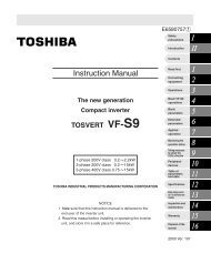
<strong>Industrial</strong> <strong>Inverter</strong><br />
For 3-phase induction motors<br />
Instruction Manual<br />
TOSVERT TM <strong>VF</strong>-<strong>FS1</strong><br />
3-phase 200V class 0.4 30kW<br />
3-phase 400V class 0.4 75kW<br />
NOTICE<br />
1. Make sure that this instruction manual is delivered to the<br />
end user of the inverter unit.<br />
2. Read this manual before installing or operating the inverter<br />
unit, and store it in a safe place for reference.<br />
E6581381<br />
Safety<br />
precautions<br />
Introduction<br />
Contents<br />
Read first<br />
Connection<br />
Operations<br />
Basic <strong>VF</strong>-<strong>FS1</strong><br />
operations<br />
Basic<br />
parameters<br />
Extended<br />
parameters<br />
Applied<br />
operation<br />
Monitoring the<br />
operation status<br />
Measures<br />
to satisfy the<br />
standards<br />
Peripheral<br />
devices<br />
Table of<br />
parameters<br />
and data<br />
Specifications<br />
Before making<br />
a service call<br />
Inspection and<br />
maintenance<br />
Warranty<br />
Disposal of the<br />
inverter<br />
2009 Ver. 118/119<br />
I<br />
II<br />
1<br />
2<br />
3<br />
4<br />
5<br />
6<br />
7<br />
8<br />
9<br />
10<br />
11<br />
12<br />
13<br />
14<br />
15<br />
16
I. Safety precautions<br />
1<br />
E6581381<br />
The items described in these instructions and on the inverter itself are very important so that you can use the<br />
inverter safely, prevent injury to yourself and other people around you as well as to prevent damage to property in<br />
the area. Thoroughly familiarize yourself with the symbols and indications shown below and then continue to read<br />
the manual. Make sure that you observe all warnings given.<br />
Explanation of markings<br />
Marking Meaning of marking<br />
Warning Indicates that errors in operation may lead to death or serious injury.<br />
Caution<br />
Indicates that errors in operation may lead to injury (*1) to people or that these errors may<br />
cause damage to physical property. (*2)<br />
(*1) Such things as injury, burns or shock that will not require hospitalization or long periods of outpatient<br />
treatment.<br />
(*2) Physical property damage refers to wide-ranging damage to assets and materials.<br />
Meanings of symbols<br />
Marking Meaning of marking<br />
Indicates prohibition (Don't do it).<br />
What is prohibited will be described in or near the symbol in either text or picture form.<br />
Indicates something mandatory (must be done).<br />
What is mandatory will be described in or near the symbol in either text or picture form.<br />
Indicates danger or warning.<br />
What is dangerous, or what the wiring should be applied be applied to will described in or near the symbol<br />
in either text or picture form.<br />
Limits in purpose<br />
This inverter is used for controlling speeds of three-phase induction motors in general industrial use.<br />
Safety precautions<br />
The inverter cannot be used in any device that would present danger to the human body or from which<br />
malfunction or error in operation would present a direct threat to human life (nuclear power control<br />
device, aviation and space flight control device, traffic device, life support or operation system, safety<br />
device, etc.). If the inverter is to be used for any special purpose, first get in touch with the supplier.<br />
This product was manufactured under the strictest quality controls but if it is to be used in critical<br />
equipment, for example, equipment in which errors in malfunctioning signal output system would cause<br />
a major accident, safety devices must be installed on the equipment.<br />
Do not use the inverter for loads other than those of properly applied three-phase induction motors in<br />
general industrial use. (Use in other than properly applied three-phase induction motors may cause an<br />
accident.)<br />
I
I General Operation<br />
Disassembly<br />
prohibited<br />
Prohibited<br />
Mandatory<br />
Prohibited<br />
contact<br />
2<br />
E6581381<br />
Warning See item<br />
• Never disassemble, modify or repair.<br />
This can result in electric shock, fire and injury. For repairs, call your sales distributor.<br />
• Never remove the front cover when power is on or open door if enclosed in a cabinet.<br />
The unit contains many high voltage parts and contact with them will result in electric shock.<br />
• Don't stick your fingers into openings such as cable wiring hole and cooling fan covers.<br />
This can result in electric shock or other injury.<br />
• Don't place or insert any kind of object into the inverter (electrical wire cuttings, rods, wires etc.).<br />
This can result in electric shock or fire.<br />
• Do not allow water or any other fluid to come in contact with the inverter.<br />
This can result in electric shock or fire.<br />
• Turn power on only after attaching the front cover or closing door if enclosed in a cabinet.<br />
If power is turned on without the front cover attached or closing door if enclosed in a<br />
cabinet, this can result in electric shock or other injury.<br />
• If the inverter begins to emit smoke or an unusual odor, or unusual sounds, immediately<br />
turn power off.<br />
If the equipment is continued in operation in such a state, the result may be fire. Call your<br />
local sales agency for repairs.<br />
• Always turn power off if the inverter is not used for long periods of time since there is a<br />
possibility of malfunction caused by leaks, dust and other material. If power is left on with<br />
the inverter in that state, it may result in fire.<br />
• Do not touch heat radiating fins or discharge resistors.<br />
These device are hot, and you'll get burned if you touch them.<br />
Caution See item<br />
2.<br />
2.1<br />
2.<br />
2.<br />
2.<br />
2.1<br />
3.<br />
3.<br />
3.
Transportation & installation<br />
Prohibited<br />
Mandatory<br />
Prohibited<br />
Mandatory<br />
Wiring<br />
Prohibited<br />
3<br />
E6581381<br />
Warning See item<br />
• Do not install or operate the inverter if it is damaged or any component is missing.<br />
This can result in electric shock or fire. Please consult your local sales agency for repairs.<br />
Call your local sales agency for repairs.<br />
• Do not place any inflammable objects nearby.<br />
If a flame is emitted due to malfunction, it may result in a fire.<br />
• Do not install in any location where the inverter could come into contact with water or<br />
other fluids.<br />
This can result in electric shock or fire.<br />
• Must be used in the environmental conditions prescribed in the instruction manual.<br />
Use under any other conditions may result in malfunction.<br />
• Mount the inverter on a metal plate.<br />
The rear panel gets very hot. Do not install in an inflammable object, this can result in fire.<br />
• Do not operate with the front panel cover removed. This can result in electric shock.<br />
Failure to do so can lead to risk of electric shock and can result in death or serious injury.<br />
• An emergency stop device must be installed that fits with system specifications (e.g. shut<br />
off input power then engage mechanical brake). Operation cannot be stopped immediately<br />
by the inverter alone, thus risking an accident or injury.<br />
• All options used must be those specified by <strong>Toshiba</strong>.<br />
The use of any other option may result in an accident.<br />
1.4.4<br />
1.4.4<br />
2.<br />
1.4.4<br />
1.4.4<br />
1.4.4<br />
1.4.4<br />
1.4.4<br />
Caution See item<br />
• When transporting or carrying, do not hold by the front panel covers.<br />
The covers may come off and the unit will drop out resulting in injury.<br />
• Do not install in any area where the unit would be subject to large amounts of vibration.<br />
That could result in the unit falling, resulting in injury.<br />
• The main unit must be installed on a base that can bear the unit's weight.<br />
If the unit is installed on a base that cannot withstand that weight, the unit may fall<br />
resulting in injury.<br />
• If braking is necessary (to hold motor shaft), install a mechanical brake.<br />
The brake on the inverter will not function as a mechanical hold, and if used for that<br />
purpose, injury may result.<br />
Warning<br />
• Do not connect input power to the output (motor side) terminals (U/T1,V/T2,W/T3).<br />
That will destroy the inverter and may result in fire.<br />
• Do not connect resistors to the DC terminals (between PA/+ and PC/-).<br />
That may cause a fire.<br />
• Within ten minutes after turning off input power, do not touch wires of devices (MCCB)<br />
connected to the input side of the inverter.<br />
That could result in electric shock.<br />
2.<br />
1.4.4<br />
1.4.4<br />
1.4.4<br />
See item<br />
2.2<br />
2.2<br />
2.2<br />
I
4<br />
E6581381<br />
I Warning See item<br />
• Electrical installation work must be done by a qualified expert.<br />
Connection of input power by someone who does not have that expert knowledge may<br />
result in fire or electric shock.<br />
2.1<br />
• Connect output terminals (motor side) correctly.<br />
If the phase sequence is incorrect, the motor will operate in reverse and that may result in<br />
injury.<br />
2.1<br />
• Wiring must be done after installation.<br />
If wiring is done prior to installation that may result in injury or electric shock<br />
2.1<br />
• The following steps must be performed before wiring.<br />
(1) Turn off all input power.<br />
2.1<br />
Mandatory (2) Wait at least ten minutes and check to make sure that the charge lamp is no longer lit.<br />
(3) Use a tester that can measure DC voltage (800VDC or more), and check to make sure<br />
that the voltage to the DC main circuits (across PA/+ and PC/-) is 45V or less.<br />
If these steps are not properly performed, the wiring will cause electric shock.<br />
• Tighten the screws on the terminal board to specified torque.<br />
If the screws are not tightened to the specified torque, it may lead to fire.<br />
2.1<br />
• Check to make sure that the input power voltage is +10%, -15% of the rated power<br />
voltage written on the rating label (±10% when the load is 100% in continuous operation).<br />
If the input power voltage is not +10%, -15% of the rated power voltage (±10% when the<br />
load is 100% in continuous operation) this may result in fire.<br />
1.4.4<br />
• Ground must be connected securely.<br />
2.1<br />
If the ground is not securely connected, it could lead to electric shock or fire when a<br />
malfunction or current leak occurs.<br />
2.2<br />
Be Grounded<br />
Prohibited<br />
Operations<br />
Prohibited<br />
Mandatory<br />
Caution See item<br />
• Do not attach equipment (such as noise filters or surge absorbers) that have built-in<br />
capacitors to the output (motor side) terminals.<br />
That could result in a fire.<br />
Warning See item<br />
• Do not touch inverter terminals when electrical power is going to the inverter even if the<br />
motor is stopped.<br />
Touching the inverter terminals while power is connected to it may result in electric shock.<br />
• Do not touch switches when the hands are wet and do not try to clean the inverter with a<br />
damp cloth.<br />
Such practices may result in electric shock.<br />
• Do not go near the motor in alarm-stop status when the retry function is selected.<br />
The motor may suddenly restart and that could result in injury.<br />
Take measures for safety, e.g. attaching a cover to the motor, against accidents when the<br />
motor unexpectedly restarts.<br />
• Turn input power on after attaching the front cover.<br />
When installed inside a cabinet and using with the front cover removed, always close the<br />
cabinet doors first and then turn power on. If the power is turned on with the front cover or<br />
the cabinet doors open, it may result in electric shock.<br />
• Make sure that operation signals are off before resetting the inverter after malfunction.<br />
If the inverter is reset before turning off the operating signal, the motor may restart<br />
suddenly causing injury.<br />
2.1<br />
3.<br />
3.<br />
3.<br />
3.<br />
3.
Prohibited<br />
5<br />
E6581381<br />
Caution See item<br />
• Observe all permissible operating ranges of motors and mechanical equipment. (Refer to<br />
the motor's instruction manual.)<br />
Not observing these ranges may result in injury.<br />
When sequence for restart after a momentary failure is selected (inverter)<br />
Mandatory<br />
Caution See item<br />
• Stand clear of motors and mechanical equipment.<br />
If the motor stops due to a momentary power failure, the equipment will start suddenly<br />
after power recovers. This could result in unexpected injury.<br />
• Attach warnings about sudden restart after a momentary power failure on inverters,<br />
motors and equipment for prevention of accidents in advance.<br />
When retry function is selected (inverter)<br />
Mandatory<br />
3.<br />
6.12.1<br />
6.12.1<br />
Caution See item<br />
• Stand clear of motors and equipment.<br />
If the motor and equipment stop when the alarm is given, selection of the retry function will<br />
restart them suddenly after the specified time has elapsed. This could result in unexpected<br />
injury.<br />
• Attach warnings about sudden restart in retry function on inverters, motors and equipment<br />
for prevention of accidents in advance.<br />
Maintenance and inspection<br />
Prohibited<br />
Mandatory<br />
Warning<br />
• Do not replace parts.<br />
This could be a cause of electric shock, fire and bodily injury. To replace parts, call the<br />
local sales agency.<br />
• The equipment must be inspected every day.<br />
If the equipment is not inspected and maintained, errors and malfunctions may not be<br />
discovered and that could result in accidents.<br />
• Before inspection, perform the following steps.<br />
(1) Turn off all input power to the inverter.<br />
(2) Wait at least ten minutes and check to make sure that the charge lamp is no longer lit.<br />
(3) Use a tester that can measure DC voltages (800VDC or more), and check to make<br />
sure that the voltage to the DC main circuits (across PA/+ and PC/-) is 45V or less.<br />
If inspection is performed without performing these steps first, it could lead to electric<br />
shock.<br />
6.12.3<br />
6.12.3<br />
See item<br />
14.2<br />
14.<br />
14.<br />
I
I Disposal<br />
Mandatory<br />
6<br />
E6581381<br />
Caution See item<br />
• If you throw away the inverter, have it done by a specialist in industry waste disposal(*).<br />
If you throw away the inverter by yourself, this can result in explosion of capacitor or<br />
produce noxious gases, resulting in injury.<br />
(*) Persons who specialize in the processing of waste and known as "industrial waste<br />
product collectors and transporters" or "industrial waste disposal persons. "If the<br />
collection, transport and disposal of industrial waste is done by someone who is not<br />
licensed for that job, it is a punishable violation of the law. (Laws in regard to cleaning<br />
and processing of waste materials)<br />
Attach warning labels<br />
Shown here are examples of warning labels to prevent, in advance, accidents in relation to inverters, motors and other<br />
equipment.<br />
Be sure to affix the caution label where it is easily visible when selecting the auto-restart function (⇒ See section<br />
6.12.1) or the retry function (⇒ See section 6.12.3).<br />
If the inverter has been programmed for restart<br />
sequence of momentary power failure, place warning<br />
labels in a place where they can be easily seen and<br />
read.<br />
(Example of warning label)<br />
Warning (Functions<br />
programmed for restart)<br />
Do not go near motors and equipment.<br />
Motors and equipment that have stopped<br />
temporarily after momentary power failure will<br />
restart suddenly after recovery.<br />
16.<br />
If the retry function has been selected, place warning<br />
labels in a location where they can be easily seen and<br />
read.<br />
(Example of warning label)<br />
Warning (Functions<br />
programmed for retry)<br />
Do not go near motors and equipment.<br />
Motors and equipment that have stopped<br />
temporarily after an alarm will restart suddenly<br />
after the specified time has elapsed.
II. Introduction<br />
Thank you for your purchase of the <strong>Toshiba</strong> "TOSVERT <strong>VF</strong>-<strong>FS1</strong>” industrial inverter.<br />
This is the Ver.118 / Ver.119 CPU version inverter.<br />
Please be informed that CPU version will be frequently upgraded.<br />
Features<br />
1. Built-in noise filter<br />
1) All models in both the 200V and 400V series have a noise filter inside.<br />
2) Can be compliant with European CE marking standard<br />
3) Reduces space requirements and cuts down on time and labor needed in wiring.<br />
2. Simple operation<br />
7<br />
E6581381<br />
1) Automatic functions (history, wizard, acceleration/deceleration time, and function programming)<br />
Just by wiring the motor to the power supply allows instant operation without the need to program<br />
parameters.<br />
2) The RUN/STOP button and LOC/REM button allow easy operation.<br />
3. Superior basic performance<br />
1) Automatic energy-saving<br />
2) Smooth operation : Reduced rotation ripple through the use of <strong>Toshiba</strong>'s unique waveform formation.<br />
3) Built-in current surge suppression circuit : Can be safely connected even if power load is low.<br />
4) Maximum 200Hz high frequency output : Optimum for use with high speed motors such as those in<br />
lumber machinery and milling machines.<br />
5) Maximum carrier frequency : 16kHz quiet operation<br />
<strong>Toshiba</strong>'s unique PWM control reduces noise at low carrier.<br />
4. Globally compatible<br />
1) Compatible with 200V and 400V power supplies<br />
2) Conforms to CE marking and with UL, CSA.<br />
3) Sink/source switching of control input.<br />
5. Options allow use with a wide variety of applications<br />
• Internal communications devices (LonWorks ® , BACnet ® , Metasys ® N2, Siemens APOGEE TM FLN.)<br />
• Extension panel/Parameter writer<br />
• EMC noise reduction filter<br />
• Other options are common to all models<br />
6. Extended power range<br />
• Wide range of powers up to 75kW for this class of inverter.<br />
II
⎯⎯ Contents ⎯⎯<br />
I Safety precautions .........................................................................................................................................................1<br />
II Introduction ....................................................................................................................................................................7<br />
i<br />
E6581381<br />
1. Read first........................................................................................................................................................................A-1<br />
1.1 Check product purchase ....................................................................................................................................A-1<br />
1.2 Contents of the product......................................................................................................................................A-2<br />
1.3 Names and functions .........................................................................................................................................A-3<br />
1.4 Notes on the application ....................................................................................................................................A-13<br />
2. Connection.....................................................................................................................................................................B-1<br />
2.1 Cautions on wiring .............................................................................................................................................B-1<br />
2.2 Standard connections ........................................................................................................................................B-2<br />
2.3 Description of terminals .....................................................................................................................................B-5<br />
3. Operations .....................................................................................................................................................................C-1<br />
3.1 Simplified operation of the <strong>VF</strong>-<strong>FS1</strong>....................................................................................................................C-2<br />
3.2 How to operate the <strong>VF</strong>-<strong>FS1</strong> ...............................................................................................................................C-6<br />
4. Basic <strong>VF</strong>-<strong>FS1</strong> operations...............................................................................................................................................D-1<br />
4.1 Flow of status monitor mode ..............................................................................................................................D-2<br />
4.2 How to set parameters .......................................................................................................................................D-3<br />
5. Basic parameters ...........................................................................................................................................................E-1<br />
5.1 Setting acceleration/deceleration time...............................................................................................................E-1<br />
5.2 Specifying an operation mode, using parameters..............................................................................................E-4<br />
5.3 Selection of operation mode ..............................................................................................................................E-7<br />
5.4 Meter setting and adjustment.............................................................................................................................E-10<br />
5.5 Standard default setting .....................................................................................................................................E-13<br />
5.6 Forward/reverse run selection (Operation panel operation) ..............................................................................E-15<br />
5.7 Maximum frequency...........................................................................................................................................E-16<br />
5.8 Upper limit and lower limit frequencies ..............................................................................................................E-16<br />
5.9 Base frequency ..................................................................................................................................................E-17<br />
5.10 Selecting control mode ......................................................................................................................................E-18<br />
5.11 Manual torque boost - increasing torque boost at low speeds...........................................................................E-24<br />
5.12 Setting the electronic thermal ............................................................................................................................E-24<br />
5.13 Preset-speed operation (speeds in 7 steps) ......................................................................................................E-28<br />
6. Extended parameters.....................................................................................................................................................F-1<br />
6.1 Input/output parameters.....................................................................................................................................F-1<br />
6.2 Input signal selection .........................................................................................................................................F-5
ii<br />
E6581381<br />
6.3 Terminal function selection ................................................................................................................................F-6<br />
6.4 Basic parameters 2............................................................................................................................................F-15<br />
6.5 Frequency priority selection ..............................................................................................................................F-16<br />
6.6 Operation frequency..........................................................................................................................................F-24<br />
6.7 DC braking.........................................................................................................................................................F-25<br />
6.8 Auto-stop in case of lower-limit frequency continuous operation ......................................................................F-26<br />
6.9 Jump frequency-jumping resonant frequencies.................................................................................................F-28<br />
6.10 Bumpless operation...........................................................................................................................................F-29<br />
6.11 PWM carrier frequency......................................................................................................................................F-30<br />
6.12 Trip-less intensification......................................................................................................................................F-34<br />
6.13 Drooping control ................................................................................................................................................F-42<br />
6.14 Conducting PID control......................................................................................................................................F-44<br />
6.15 Setting motor constants .....................................................................................................................................F-48<br />
6.16 Acceleration/deceleration time 2 .......................................................................................................................F-53<br />
6.17 Protection functions...........................................................................................................................................F-57<br />
6.18 Forced fire-speed control function.....................................................................................................................F-71<br />
6.19 Adjustment parameters......................................................................................................................................F-72<br />
6.20 Operation panel parameter................................................................................................................................F-73<br />
6.21 Communication function (RS485)......................................................................................................................F-82<br />
6.22 Parameters for options ......................................................................................................................................F-87<br />
6.23 Permanent magnetic motors..............................................................................................................................F-87<br />
7. Applied operation ..........................................................................................................................................................G-1<br />
7.1 Setting the operation frequency ........................................................................................................................G-1<br />
7.2 Setting the operation mode ...............................................................................................................................G-5<br />
8. Monitoring the operation status .....................................................................................................................................H-1<br />
8.1 Status monitor mode..........................................................................................................................................H-1<br />
8.2 Display of trip information..................................................................................................................................H-5<br />
9. Measures to satisfy the standards.................................................................................................................................I-1<br />
9.1 How to cope with the CE directive.....................................................................................................................I-1<br />
9.2 Compliance with UL Standard and CSA Standard .............................................................................................I-5<br />
10. Peripheral devices.........................................................................................................................................................J-1<br />
10.1 Selection of wiring materials and devices .........................................................................................................J-1<br />
10.2 Installation of a magnetic contactor ...................................................................................................................J-3<br />
10.3 Installation of an overload relay.........................................................................................................................J-4<br />
10.4 Optional external devices ..................................................................................................................................J-5<br />
11. Table of parameters and data........................................................................................................................................K-1<br />
11.1 User parameters................................................................................................................................................K-1<br />
11.2 Basic parameters...............................................................................................................................................K-1<br />
11.3 Extended parameters ........................................................................................................................................K-4
iii<br />
E6581381<br />
12. Specifications................................................................................................................................................................L-1<br />
12.1 Models and their standard specifications...........................................................................................................L-1<br />
12.2 Outside dimensions and mass ...........................................................................................................................L-4<br />
13. Before making a service call - Trip information and remedies .......................................................................................M-1<br />
13.1 Trip causes/warnings and remedies ..................................................................................................................M-1<br />
13.2 Restoring the inverter from a trip .......................................................................................................................M-5<br />
13.3 If the motor does not run while no trip message is displayed ............................................................................M-6<br />
13.4 How to determine the causes of other problems................................................................................................M-7<br />
14. Inspection and maintenance ..........................................................................................................................................N-1<br />
14.1 Regular inspection .............................................................................................................................................N-1<br />
14.2 Periodical inspection..........................................................................................................................................N-2<br />
14.3 Making a call for servicing .................................................................................................................................N-5<br />
14.4 Keeping the inverter in storage..........................................................................................................................N-5<br />
15. Warranty ........................................................................................................................................................................O-1<br />
16. Disposal of the inverter ..................................................................................................................................................P-1
1. Read first<br />
1.1 Check product purchase<br />
Mandatory<br />
Rating label<br />
Series name<br />
Power supply<br />
Motor capacity<br />
Carton box<br />
Before using the product you have purchased, check to make sure that it is exactly what you ordered.<br />
Caution<br />
Instruction manual<br />
This manual<br />
A-1<br />
E6581381<br />
Use an inverter that conforms to the specifications of power supply and three-phase induction<br />
motor being used. If the inverter being used does not conform to those specifications, not only will<br />
the three-phase induction motor not rotate correctly, it may also cause serious accidents through<br />
overheating and fire.<br />
<strong>VF</strong>-<strong>FS1</strong><br />
3PH-200/240V-0.75kW/1HP<br />
Type indication label<br />
<strong>Inverter</strong> main unit<br />
Rating label<br />
Warning label<br />
Warning label<br />
EMC plate<br />
18.5kW or less of<br />
WP models only<br />
Name plate<br />
Name plate<br />
<strong>Inverter</strong> Type<br />
<strong>Inverter</strong> rated output<br />
capacity<br />
Power supply<br />
Related input current<br />
Related output<br />
current<br />
1
1<br />
1.2 Contents of the product<br />
Explanation of the name plate label.<br />
A-2<br />
E6581381<br />
Type Form<br />
V F F S 1 - 4 0 0 7 P L E - W N - A 2 2<br />
Model name<br />
TOSVERT<br />
<strong>VF</strong>-<strong>FS1</strong>series<br />
Input (AC) voltage<br />
2 : 200V to 240V<br />
4 : 380V to 480V<br />
Applicable motor<br />
capacity<br />
004 : 0.4kW<br />
007 : 0.75kW<br />
015 : 1.5kW<br />
022 : 2.2kW<br />
037 : 4.0kW<br />
055 : 5.5kW<br />
075 : 7.5kW<br />
110 : 11kW<br />
150 : 15kW<br />
185 :18.5kW<br />
220 : 22kW<br />
300 : 30kW<br />
370 : 37kW<br />
450 : 45kW<br />
550 : 55kW<br />
750 : 75kW<br />
Additional functions I<br />
None: No filter inside<br />
M: Built-in basic filter<br />
L: Built-in<br />
EMI class A filter<br />
D: Built-in<br />
EMI class B filter<br />
Operation panel<br />
P: Provided<br />
Default interface<br />
logic*<br />
WN : Negative<br />
WP : Positive<br />
Additional functions II<br />
None: Standard product<br />
E: Enclosed type<br />
Special specification code<br />
A:is the number<br />
* This code represents the factory default logic setting. You can switch from one input/output logic to the other using<br />
slide switch SW4. ⇒ See section 2.3.2.<br />
Warning: Always shut power off first then check the ratings label of inverter held in a cabinet.
1.3 Names and functions<br />
1.3.1 Outside view<br />
[Operation panel]<br />
A-3<br />
E6581381<br />
1
1<br />
Charge lamp<br />
Indicates that high voltage is still<br />
present within the inverter. Do not<br />
open the terminal board cover<br />
while this is lit.<br />
Front panel<br />
The front panel of the inverter or<br />
terminal board<br />
To avoid touching the terminal<br />
board by mistake, be sure to close<br />
the front panel before starting<br />
operation.<br />
Communicatio Connector hole<br />
Cnotrol cable port<br />
Main circuit<br />
cable port<br />
[Front]<br />
Top warning label Note)<br />
[Bottom] [Right side]<br />
A-4<br />
Unlock position mark<br />
E6581381<br />
The front panel is unlocked when<br />
the dot on the locking screw is on<br />
this (upper) side.<br />
Front panel locking screw<br />
The inverter came with this<br />
screw in the locked position.<br />
So from this position, turn the<br />
screw 90° counterclockwise to<br />
unlock the front panel, or turn<br />
it 90° clockwise to lock the<br />
front panel.<br />
The screw does not turn 360°. To<br />
avoid damage to the screw, do<br />
not use excessive force when<br />
turning it.<br />
Lock position mark<br />
The front panel is locked when the<br />
dot on the locking screw is on this<br />
(lower) side.<br />
Colling fin<br />
Ventilation slit<br />
Name plate<br />
Note: Remove this seal and operate it at a current lower than the rated one when installing the inverter side by side with<br />
other inverters where the ambient temperature will rise above 40°C.
・Monitor display<br />
The LEDs on the operation panel display the following symbols indicate operations and parameters.<br />
LED(number)<br />
0 1 2 3 4 5 6 7 8 9 -<br />
0 1 2 3 4 5 6 7 8 9 -<br />
LED(alphabet)<br />
Aa Bb C c Dd Ee Ff Gg H h I i Jj Kk Ll<br />
a b c w d e f g h k i } j l<br />
Mm Nn O o Pp Qq Rr Ss Tt Uu Vv Ww Xx Yy Zz<br />
m n o x p q r s t u v y<br />
Example of the label<br />
1.3.2 Power circuit and control circuit terminal boards<br />
A-5<br />
E6581381<br />
In case of the lug connector, cover the lug connector with insulated tube, or use the insulated lug connector.<br />
1) Power circuit terminal board<br />
In case of the lug connector, cover the lug connector with insulated tube, or use the insulated lug<br />
connector.<br />
Screw size tightening torque<br />
M4 screw 1.3Nm 10.7lb in<br />
M5 screw 2.5Nm 22.3lb in<br />
M6 screw 4.5Nm 40.1lb in<br />
M8 screw 12Nm 106lb in<br />
M12 screw 41Nm 360lb in<br />
1
1<br />
<strong>VF</strong><strong>FS1</strong>-2004 ∼ 2037PM<br />
<strong>VF</strong><strong>FS1</strong>-4004 ∼ 4055PL<br />
Note: EMC plate is supplied as standard only WP model.<br />
A-6<br />
E6581381
<strong>VF</strong><strong>FS1</strong>-2055, 2075PM<br />
-4075, 4110PL<br />
<strong>VF</strong><strong>FS1</strong>-2110 ∼ 2185PM<br />
-4150 ∼ 4185PL<br />
Note: EMC plate is supplied as standard only WP model.<br />
A-7<br />
E6581381<br />
1
1<br />
<strong>VF</strong><strong>FS1</strong>-2220PM<br />
-4220, 4300, 4370, 4450PL<br />
Grounding capacitor<br />
disconnecting switch<br />
(4220, 4300PL only)<br />
(⇒See page A-10)<br />
<strong>VF</strong><strong>FS1</strong>-2300PM<br />
-4550, 4750PL<br />
Each main circuit terminal has the<br />
structure shown in the figure below.<br />
Connect a cable to part A if it has a<br />
ring terminal, or to part B if it has no<br />
terminal (bare wire).<br />
Parts A and B accommodate different<br />
sizes of cables, so consult the cable<br />
size list for the size of cable<br />
connectable to each part.<br />
A<br />
B<br />
Note: EMC plate is supplied as option.<br />
A-8<br />
(⇒See page A-10)<br />
Grounding capacitor<br />
disconnecting switch<br />
(400V only)<br />
(⇒See page A-10)<br />
E6581381
Mandatory<br />
2) Grounding capacitor disconnecting switch and taps<br />
Caution<br />
A-9<br />
E6581381<br />
The grounding capacitor disconnecting tap is provided with a protection cover. To avoid shock hazards,<br />
always attach the cover after connecting or disconnecting the capacitor to or from the tap.<br />
Every three-phase 400V model has a built-in high-attenuation noise filter, which is grounded through a<br />
capacitor.<br />
If you want to disconnect the capacitor from the grounding line to reduce the amount of leakage current,<br />
you can do so easily using the switch or tap. Keep in mind, however, that disconnecting the capacitor<br />
from the grounding line causes the inverter to become non-compliant with the EMC directive. Also note<br />
that the inverter must always be turned off before the capacitor is disconnected or reconnected.<br />
Note: In case of three phase 400V-5.5kW or less model, if you disconnect the capacitor from ground,<br />
set the parameter of carrier frequency to 6kHz with motor cable length 30m or less.<br />
5.5kW or less : Switch<br />
7.5∼18.5kW: Tap<br />
To connect the capacitor to ground, push this switch.<br />
(Factory default position)<br />
To disconnect the capacitor from ground, pull up this switch.<br />
To disconnect the capacitor from ground, connect the lug terminal<br />
to this tap.<br />
To connect the capacitor to ground, connect the lug terminal to<br />
this tap. (Factory default setting)<br />
1
1<br />
22kW or more: Switch<br />
3) Control circuit terminal board<br />
The control circuit terminal board is common to all equipment.<br />
Connector for RS485<br />
communications and<br />
option (RJ45)<br />
Wire size Factory default settings of slide switches<br />
Solid wire: 0.3 ∼ 1.5 (mm 2 ) SW4: SINK (Negative) side (WN type)<br />
Stranded wire: 0.3 ∼ 1.5 (mm 2 ) FM (SW2): V side<br />
(AWG 22 ∼ 16) VIA (SW3): V side<br />
Sheath strip length: 6 (mm)<br />
A-10<br />
SOURCE (Positive) side (WP type)<br />
Screwdriver: Small-sized flat-blade screwdriver<br />
(Blade thickness: 0.6 mm or less, blade width: 3.5 mm or less)<br />
⇒ See section 2.3.2 for details on all terminal functions.<br />
To change the capacitance from Small to Large, push this<br />
switch. (Factory default position)<br />
To change the capacitance from Large to Small, pull up this<br />
switch.<br />
E6581381<br />
M3 screw<br />
0.5N•m<br />
4.4 lb・in
A-11<br />
E6581381<br />
1.3.3 How to open the front (terminal board) cover-18.5kW or less<br />
To wire the terminal board, remove the front lower cover in line with the steps given below.<br />
(1) (2)<br />
Turn the locking screw on the right side of the front panel 90°<br />
counterclockwise to align the dot on the screw with the unlock<br />
position mark (upper side). To avoid damage to the screw, do<br />
not apply excessive force to turn the screw more than 90 degrees.<br />
(3) (4)<br />
Terminal board cover<br />
Remove the terminal board cover by pulling it up toward you.<br />
Pull the front panel toward you<br />
and swing it open to the left.<br />
Wiring port cover<br />
Remove the wiring port cover by pulling it down,<br />
pass cables through the wiring port, and connect<br />
the cables to the terminal board.<br />
1
1<br />
A-12<br />
E6581381<br />
1.3.4 How to open the front (terminal board) cover-22kW or<br />
more<br />
To wire the main circuit terminal board for models 22kW or more, remomve the front cover.<br />
Remove the screw<br />
Maincircuit terminal board<br />
Open the control circuit terminal board cover.<br />
* To open the cover, lift it with your finger placed<br />
at the part on the right side of the cover.<br />
Control circuit terminal board
1.4 Notes on the application<br />
1.4.1 Motors<br />
Mandatory<br />
When the <strong>VF</strong>-<strong>FS1</strong> and the motor are used in conjunction, pay attention to the following items.<br />
Caution<br />
A-13<br />
E6581381<br />
Use an inverter that conforms to the specifications of power supply and three-phase induction motor<br />
being used. If the inverter being used does not conform to those specifications, not only will the threephase<br />
induction motor not rotate correctly, but it may cause serious accidents through overheating and<br />
fire.<br />
Comparisons with commercial power operation.<br />
The <strong>VF</strong>-<strong>FS1</strong> <strong>Inverter</strong> employs the sinusoidal PWM system. However, the output voltage and output<br />
current are not perfect sine waves, they have a distorted wave that is close to sinusoidal waveform.<br />
This is why compared to operation with a commercial power there will be a slight increase in motor<br />
temperature, noise and vibration.<br />
Operation in the low-speed area<br />
When running continuously at low speed in conjunction with a general purpose motor, there may be a<br />
decline in that motor's cooling effect. If this happens, operate with the output decreased from rated load.<br />
To carry out low-speed operation continuously at the rated torque, we recommend to use a inverter<br />
rated motor or a forced cooled motor designed for use with an inverter. When operating in conjunction<br />
with a inverter rated motor, you must change the inverter's motor overload protection level to <strong>VF</strong> motor<br />
use ().<br />
Adjusting the overload protection level<br />
The <strong>VF</strong>-<strong>FS1</strong> <strong>Inverter</strong> protects against overloads with its overload detection circuits (electronic thermal).<br />
The electronic thermal's reference current is set to the inverter's rated current, so it must be adjusted in<br />
line with the rated current of the general purpose motor being used in combination.<br />
High speed operation at and above 60Hz<br />
Operating at frequencies greater than 60Hz will increase noise and vibration. There is also a possibility<br />
this will exceed the motor's mechanical strength limits and the bearing limits so you should inquire to<br />
the motor's manufacturer about such operation.<br />
Method of lubricating load mechanisms<br />
Operating an oil-lubricated reduction gear and gear motor in the low-speed areas will worsen the<br />
lubricating effect. Check with the manufacturer of the reduction gear to find out about operable gearing<br />
area.<br />
1
1<br />
Low loads and low inertia loads<br />
A-14<br />
E6581381<br />
The motor may demonstrate instability such as abnormal vibrations or overcurrent trips at light loads of<br />
5 % or under of the load percentage, or when the load's inertia moment is extremely small. If that<br />
happens reduce the carrier frequency.<br />
Occurrence of instability<br />
Unstable phenomena may occur with the load and motor combinations shown below.<br />
⋅ Combined with a motor that exceeds applicable motor ratings recommended for the inverter<br />
⋅ Combined with special motors<br />
To deal with the above lower the settings of inverter carrier frequency.<br />
⋅ Combined with couplings between load devices and motors with high backlash<br />
When using the inverter in the above combination, use the S-pattern acceleration/deceleration function,<br />
or when vector control is selected, adjust the speed control response/stability factor or switch to V/F<br />
control mode.<br />
⋅ Combined with loads that have sharp fluctuations in rotation such as piston movements<br />
In this case, please do not use this inverter.<br />
Braking a motor when cutting off power supply<br />
A motor with its power cut off goes into free-run, and does not stop immediately. To stop the motor<br />
quickly as soon as the power is cut off install an auxiliary brake. There are different kinds of brake<br />
devices, both electrical and mechanical. Select the brake that is best for the system.<br />
Load that produces regenerative torque<br />
Do not use the inverter in combination with a load, such as an air conditioner, that produces<br />
regenerative torque. Or the overvoltage or overcurrent protection circuit of the inverter may be activated,<br />
causing the inverter to trip. If overvoltage tripping occurs during deceleration, lengthen the deceleration<br />
time.
Braking motor<br />
A-15<br />
E6581381<br />
When using a braking motor, if the braking circuit is directly connected to the inverters's output<br />
terminals, the brake cannot be released because of the lowered starting voltage. Therefore, when<br />
using a braking motor, connect the braking circuit to the inverter's power supply side, as shown in the<br />
figure below. Usually, braking motors produce larger noise in low speed ranges.<br />
Note: In the case of the circuit shown on the below, assign the function of detecting low-speed signals<br />
to the RY and RC terminals. Make sure the parameter is set to (factory default<br />
setting).<br />
Measures to protect motors against surge voltages<br />
In a system in which a 400V-class inverter is used to control the operation of a motor, very high surge<br />
voltages may be produced. When applied to the motor coils repeatedly for a long time, may cause<br />
deterioration of their insulation, depending on the cable length, cable routing and types of cables used.<br />
Here are some examples of measures against surge voltages.<br />
(1) Lower the inverter’s carrier frequency.<br />
(2) Set the parameter (Carrier frequency control mode selection) to or .<br />
(3) Use a motor with high insulation strength.<br />
(4) Insert an AC reactor or a surge voltage suppression filter between the inverter and the motor.<br />
1.4.2 <strong>Inverter</strong>s<br />
Protecting inverters from overcurrent<br />
The inverter has an overcurrent protection function. The programmed current level is set to the<br />
inverter's maximum applicable motor. If the motor used has a small capacity, the overcurrent level and<br />
the electronic thermal protection must be readjusted. If adjustment is necessary, see 5.12, and make<br />
adjustments as directed.<br />
<strong>Inverter</strong> capacity<br />
Do not use a small-capacity (kVA) inverter to control the operation of a large-capacity motor , no matter<br />
how light the load is. Current ripple will raise the output peak current making it easier to set off the<br />
overcurrent trip.<br />
1
1<br />
Power factor correction capacitor<br />
A-16<br />
E6581381<br />
Power factor correction capacitors cannot be installed on the output side of the inverter. When a motor<br />
is run that has a power factor correction capacitor attached to it, remove the capacitors. This can cause<br />
inverter malfunction trips and capacitor destruction.<br />
<strong>Inverter</strong><br />
U/T1<br />
V/T2<br />
W/T3<br />
Operating at other than rated voltage<br />
IM<br />
Remove the power factor correction<br />
capacitor and surge absorber<br />
Power factor correction capacitor<br />
Connections to voltages other than the rated voltage described in the rating label cannot be made. If a<br />
connection must be made to a power supply other than one with rated voltage, use a transformer to<br />
raise or lower the voltage to the rated voltage.<br />
Circuit breaking when two or more inverters are used on the same power line.<br />
MCCB1<br />
MCCB2<br />
MCCB3<br />
MCCBn+1<br />
(circuit breaking fuse)<br />
INV1<br />
Breaking of selected inverter<br />
There is no fuse in the inverter's main circuit. Thus, as the diagram above shows, when more than one<br />
inverter is used on the same power line, you must select interrupting characteristics so that only the<br />
MCCB2 will trip and the MCCB1 will not trip when a short occurs in the inverter (INV1). When you<br />
cannot select the proper characteristics install a circuit interrupting fuse between the MCCB2 and the<br />
INV1.<br />
If power supply distortion is not negligible<br />
If the power supply distortion is not negligible because the inverter shares a power distribution line with<br />
other systems causing distorted waves, such as systems with thyristors or large-capacity inverters,<br />
install an input reactor to improve the input power factor, to reduce higher harmonics, or to suppress<br />
external surges.<br />
INV2<br />
INVn
Disposal<br />
If an inverter is no longer usable, dispose of it as industrial waste.<br />
1.4.3 What to do about the leak current<br />
Caution<br />
A-17<br />
E6581381<br />
Current may leak through the inverter's input/output wires because of insufficient electrostatic capacity on the motor with<br />
bad effects on peripheral equipment.<br />
The leakage current’s value is affected by the carrier frequency and the length of the input/output wires. Test and adopt<br />
the following remedies against leak current.<br />
(1) Effects of leak current across ground<br />
Power<br />
supply<br />
Leakage current may flow not just through the inverter system but also through ground wires to other<br />
systems. Leakage current will cause earth leakage breakers, leakage current relays, ground relays, fire<br />
alarms and sensors to operate improperly, and it will cause superimposed noise on the CRT screen or<br />
display of incorrect current detection with the CT.<br />
ELCB<br />
ELCB<br />
Leakage current path across ground<br />
Remedies:<br />
<strong>Inverter</strong><br />
<strong>Inverter</strong><br />
1.If there is no radio-frequency interference or similar problem, detach the built-in noise filter<br />
capacitor, using the grounding capacitor disconnecting switch or tap. ⇒ See section 1.3.2-2.<br />
2.Reduce PWM carrier frequency.<br />
The setting of PWM carrier frequency is done with the parameter .<br />
Although the electromagnetic noise level is reduced, the motor acoustic noise is increased.<br />
3. Use high frequency remedial products for earth leakage breakers.<br />
M<br />
M<br />
1
1<br />
(2) Affects of leakage current across lines<br />
Power<br />
supply<br />
<strong>Inverter</strong><br />
Leakage current path across wires<br />
A-18<br />
Thermal relays<br />
CT<br />
A<br />
M<br />
E6581381<br />
(1) Thermal relays<br />
The high frequency component of current leaking into electrostatic capacity between inverter output<br />
wires will increase the effective current values and make externally connected thermal relays<br />
operate improperly. If the wires are more than 50 meters long, it will be easy for the external<br />
thermal relay to operate improperly with models having motors of low rated current (several<br />
A(ampere) or less), especially the 400V class low capacity (5.5kW or less) models, because the<br />
leak current will increase in proportion to the motor rating.<br />
Remedies:<br />
1.Use the electronic thermal built into the inverter. ⇒ See section 5.12.<br />
The setting of the electronic thermal is done using parameter , .<br />
2.Reduce the inverter's PWM carrier frequency. However, that will increase the motor's magnetic<br />
noise.<br />
The setting of PWM carrier frequency is done with the parameter . ⇒ See section 6.11.<br />
3.This can be improved by installing 0.1µ~0.5µF - 1000V film capacitor to the input/output terminals of<br />
each phase in the thermal relay.<br />
U/T1<br />
V/T2<br />
W/T3<br />
Thermal relays<br />
IM
A-19<br />
E6581381<br />
(2) CT and ammeter<br />
If a CT and ammeter are connected externally to detect inverter output current, the leak current's high<br />
frequency component may destroy the ammeter. If the wires are more than 50 meters long, it will be<br />
easy for the high frequency component to pass through the externally connected CT and be<br />
superimposed on and burn the ammeter with models having motors of low rated current (several<br />
A(ampere) or less), especially the 400V class low capacity (5.5kW or less) models, because the leak<br />
current will increase in proportion to the motor's rated current.<br />
Remedies:<br />
1.Use a meter output terminal in the inverter control circuit.<br />
The load current can be output on the meter output terminal (FM). If the meter is connected, use an<br />
ammeter of 1mAdc full scale or a voltmeter of 7.5V(10V)-1mA full scale.<br />
0-20mAdc (4-20mAdc) can be also output. ⇒ See section 5.4.<br />
2.Use the monitor functions built into the inverter.<br />
Use the monitor functions on the panel built into the inverter to check current values.<br />
⇒See section 8.1.1.<br />
1.4.4 Installation<br />
Prohibited<br />
Mandatory<br />
Prohibited<br />
Mandatory<br />
Installation environment<br />
The <strong>VF</strong>-<strong>FS1</strong> <strong>Inverter</strong> is an electronic control instrument. Take full consideration to installing it in the proper<br />
operating environment.<br />
Warning<br />
• Do not place any inflammable substances near the <strong>VF</strong>-<strong>FS1</strong> <strong>Inverter</strong>.<br />
If an accident occurs in which flame is emitted, this could lead to fire.<br />
• Operate under the environmental conditions prescribed in the instruction manual.<br />
Operations under any other conditions may result in malfunction.<br />
Caution<br />
• Do not install the <strong>VF</strong>-<strong>FS1</strong> <strong>Inverter</strong> in any location subject to large amounts of vibration.<br />
This could cause the unit to fall, resulting in bodily injury.<br />
• Check to make sure that the input power voltage is +10%, -15% of the rated power voltage written on<br />
the rating label (±10% when the load is 100% in continuous operation) If the input power voltage is not<br />
+10%, -15% of the rated power voltage (±10% when the load is 100% in continuous operation) this<br />
may result in fire.<br />
1
1<br />
A-20<br />
E6581381<br />
• Do not install in any location of high temperature, high humidity,<br />
moisture condensation and freezing and avoid locations where<br />
there is exposure to water and/or where there may be large<br />
amounts of dust, metallic fragments and oil mist.<br />
• Do not install in any location where corrosive gases or grinding<br />
fluids are present.<br />
• Operate in areas where ambient temperature ranges from -10°C to 60°C.<br />
When installing the inverter where the ambient temperature will rise above 40°C, remove the label<br />
(seal) from the top and operate it at a current lower than the rated one.<br />
5cm 5cm<br />
5cm<br />
Measurement position<br />
Measurement position<br />
Note: The inverter is a heat-emitting body. Make sure proper space and ventilation is provided when<br />
installing in the cabinet. When installing inside a cabinet, we recommend the top seal peeled off<br />
although 40°C or less.<br />
• Do not install in any location that is subject to large amounts of vibration.<br />
Note: If the <strong>VF</strong>-<strong>FS1</strong> <strong>Inverter</strong> is installed in a location that is subject<br />
to vibration, anti-vibration measures are required. Please<br />
consult with <strong>Toshiba</strong> about these measures.<br />
• If the <strong>VF</strong>-<strong>FS1</strong> <strong>Inverter</strong> is installed near any of the equipment listed below, provide measures to insure<br />
against errors in operation.<br />
Resistors<br />
Solenoids: Attach surge suppressor on coil.<br />
Brakes: Attach surge suppressor on coil.<br />
Magnetic contactors: Attach surge suppressor on coil.<br />
Fluorescent lights: Attach surge suppressor on coil.<br />
Resistors: Place far away from <strong>VF</strong>-<strong>FS1</strong> <strong>Inverter</strong>.
Prohibited<br />
Mandatory<br />
Mandatory<br />
How to install<br />
Warning<br />
A-21<br />
E6581381<br />
• Do not install or operate the inverter if it is damaged or any component is missing.<br />
This can result in electric shock or fire. Please consult your local sales agency for repairs. Call your<br />
local sales agency for repairs.<br />
• Mount the inverter on a metal plate.<br />
The rear panel gets very hot. Do not install in an inflammable object, this can result in fire.<br />
• Do not operate with the front panel cover removed.<br />
This can result in electric shock.<br />
• An emergency stop device must be installed that fits with system specifications (e.g. shut off input<br />
power then engage mechanical brake).<br />
Operation cannot be stopped immediately by the inverter alone, thus risking an accident or injury.<br />
• All options used must be those specified by <strong>Toshiba</strong>.<br />
The use of any other option may result in an accident.<br />
Caution<br />
• The main unit must be installed on a base that can bear the unit's weight.<br />
If the unit is installed on a base that cannot withstand that weight, the unit may fall resulting in injury.<br />
• If braking is necessary (to hold motor shaft), install a mechanical brake.<br />
The brake on the inverter will not function as a mechanical hold, and if used for that purpose, injury<br />
may result.<br />
Install the inverter in a well-ventilated indoor place and mount it on a flat metal plate in portrait orientation.<br />
If you are installing more than one inverter, the separation between inverters should be at least 5 centimeters,<br />
and they should be arranged in horizontal rows. If the inverters are horizontally arranged with no space<br />
between them (side-by-side installation), peel off the ventilation seals on top of the inverter. It is necessary to<br />
decrease the current if the inverter is operated at over 40°C.<br />
•Standard installation •Side-by-side installation<br />
10 cm or more<br />
5 cm or more<br />
<strong>VF</strong>-<strong>FS1</strong> <strong>VF</strong>-<strong>FS1</strong> <strong>VF</strong>-<strong>FS1</strong> <strong>VF</strong>-<strong>FS1</strong><br />
5 cm or more<br />
10 cm or more<br />
10 cm or more<br />
10 cm or more<br />
Remove seals on top<br />
The space shown in the diagram is the minimum allowable space. Because air cooled equipment has cooling<br />
fans built in on the top or bottom surfaces, make the space on top and bottom as large as possible to allow<br />
for air passage.<br />
Note: Do not install in any location where there is high humidity or high temperatures and where there are<br />
large amounts of dust, metallic fragments and oil mist.<br />
1
1<br />
Calorific values of the inverter and the required ventilation<br />
A-22<br />
E6581381<br />
About 5% of the rated power of the inverter will be lost as a result of conversion from AC to DC or from DC to<br />
AC. In order to suppress the rise in temperature inside the cabinet when this loss becomes heat loss, the<br />
interior of the cabinet must be ventilated and cooled.<br />
The amount of forcible air-cooling ventilation required and the necessary heat discharge surface quantity<br />
when operating in a sealed cabinet according to motor capacity are as follows.<br />
Note1: The heat loss for the optional external devices (input reactor, radio noise reduction filters, etc.) is not<br />
included in the calorific values in the table<br />
Note2: Case of 100% Load Continuation operation.<br />
Voltage class<br />
Three-Phase<br />
200V class<br />
Three-Phase<br />
400V class<br />
Operating motor<br />
capacity<br />
(kW)<br />
Calorific Values (w)<br />
Carrier frequency<br />
8kHz<br />
Carrier frequency<br />
12kHz<br />
Amount of forcible air<br />
cooling ventilation required<br />
(m 3 /min)<br />
Heat discharge surface<br />
area required for sealed<br />
storage cabinet(m 2 )<br />
0.4 - 44 0.25 0.88<br />
0.75 - 63 0.36 1.26<br />
1.5 - 101 0.58 2.02<br />
2.2 - 120 0.68 2.4<br />
4.0 - 193 1.1 3.86<br />
5.5 - 249 1.42 4.98<br />
7.5 - 346 1.97 6.92<br />
11 - 459 2.62 9.18<br />
15 - 629 3.59 12.58<br />
18.5 698 - 3.98 13.96<br />
22 763 - 4.35 15.26<br />
30 1085 - 6.18 21.7<br />
0.4 - 45 0.26 0.9<br />
0.75 - 55 0.31 1.1<br />
1.5 - 78 0.44 1.56<br />
2.2 - 103 0.59 2.06<br />
4.0 - 176 1.0 3.52<br />
5.5 - 215 1.23 4.3<br />
7.5 - 291 1.66 5.82<br />
11 - 430 2.45 8.6<br />
15 - 625 3.56 12.5<br />
18.5 603 - 3.44 12.06<br />
22 626 - 3.57 12.52<br />
30 847 - 4.83 16.94<br />
37 980 - 5.59 19.60<br />
45 1257 - 7.17 25.14<br />
55 1459 - 8.32 29.18<br />
75 1949 - 11.11 38.98<br />
Panel designing taking into consideration the effects of noise<br />
The inverter generates high frequency noise. When designing the control panel setup, consideration must be<br />
given to that noise. Examples of measures are given below.<br />
• Wire so that the main circuit wires and the control circuit wires are separated. Do not place them in the<br />
same conduit, do not run them parallel, and do not bundle them.<br />
• Provide shielding and twisted wire for control circuit wiring.
A-23<br />
E6581381<br />
• Separate the input (power) and output (motor) wires of the main circuit. Do not place them in the same<br />
conduit, do not run them parallel, and do not bundle them.<br />
• Ground the inverter ground terminals ( ).<br />
• Install surge suppressor on any magnetic contactor and relay coils used around the inverter.<br />
• Install noise filters if necessary.<br />
• Install EMC plate and use shielded wires.<br />
EMC plate<br />
Installing more than one unit in a cabinet<br />
If you are installing two or more inverters in one cabinet, pay attention to the following.<br />
• <strong>Inverter</strong>s may be installed side by side with each other with no space left between them.<br />
• When installing inverters side by side, detach the caution label on the top surface of each inverter and<br />
use them where the ambient temperature will not rise above 40°C.<br />
When using inverters where the ambient temperature will rise above 40°C, leave a space of 5 cm or<br />
more between them and remove the caution label from the top of each inverter, and operate each<br />
inverter at a current lower than the rated one.<br />
• Ensure a space of at least 20 centimeters on the top and bottom of the inverters.<br />
• Install an air deflecting plate so that the heat rising up from the inverter on the bottom does not affect the<br />
inverter on the top.<br />
Ventilation fan<br />
<strong>Inverter</strong><br />
Air deflecting plate<br />
<strong>Inverter</strong><br />
1
2. Connection<br />
Disassembly<br />
prohibited<br />
Prohibited<br />
Prohibited<br />
Warning<br />
• Never disassemble, modify or repair.<br />
This can result in electric shock, fire and injury. For repairs, call your sales agency.<br />
B-1<br />
E6581381<br />
• Don't stick your fingers into openings such as cable wiring hole and cooling fan covers.<br />
This can result in electric shock or other injury.<br />
• Don't place or insert any kind of object into the inverter (electrical wire cuttings, rods, wires). This can<br />
result in electric shock or fire.<br />
• Do not allow water or any other fluid to come in contact with the inverter.<br />
That may result in electric shock or fire.<br />
Caution<br />
• When transporting or carrying, do not hold by the front panel covers.<br />
The covers may come off and the unit will drop out resulting in injury.<br />
2.1 Cautions on wiring<br />
Prohibited<br />
Mandatory<br />
Warning<br />
• Never remove the front cover when power is on or open door if enclosed in a cabinet.<br />
The unit contains many high voltage parts and contact with them will result in electric shock.<br />
• Turn power on only after attaching the front cover or closing door if enclosed in a cabinet.<br />
If power is turned on without the front cover attached or closing door if enclosed in a cabinet. This can<br />
result in electric shock or other injury.<br />
• Electrical construction work must be done by a qualified expert.<br />
Connection of input power by someone who does not have that expert knowledge may result in fire or<br />
electric shock.<br />
• Connect output terminals (motor side) correctly.<br />
If the phase sequence is incorrect, the motor will operate in reverse and that may result in injury.<br />
• Wiring must be done after installation.<br />
If wiring is done prior to installation that may result in injury or electric shock.<br />
• The following steps must be performed before wiring.<br />
(1) Shut off all input power.<br />
(2) Wait at least ten minutes and check to make sure that the charge lamp is no longer lit.<br />
(3) Use a tester that can measure DC voltage (800VDC or more), and check to make sure that the<br />
voltage to the DC main circuits (across PA/+ and PC/-) is 45V or less.<br />
If these steps are not properly performed, the wiring will cause electric shock.<br />
• Tighten the screws on the terminal board to specified torque.<br />
If the screws are not tightened to the specified torque, it may lead to fire.<br />
2
2<br />
Be Grounded<br />
Prohibited<br />
Warning<br />
B-2<br />
E6581381<br />
• Ground must be connected securely.<br />
If the ground is not securely connected, it could lead to electric shock or fire when a malfunction or<br />
current leak occurs.<br />
Caution<br />
• Do not attach devices with built-in capacitors (such as noise filters or surge absorber) to the output<br />
(motor side) terminal.<br />
This could cause a fire.<br />
Preventing radio noise<br />
To prevent electrical interference such as radio noise, separately bundle wires to the main circuit's power<br />
terminals (R/L1, S/L2, T/L3) and wires to the motor terminals (U/T1, V/T2, W/T3).<br />
Control and main power supply<br />
The control power supply and the main circuit power supply for the <strong>VF</strong>-<strong>FS1</strong> are the same.<br />
⇒ See section 6.17.3.<br />
If a malfunction or trip causes the main circuit to be shut off, control power will also be shut off. When<br />
checking the cause of the malfunction or the trip, use the trip holding retention selection parameter.<br />
Wiring<br />
• Because the space between the main circuit terminals is small use sleeved pressure terminals for the<br />
connections. Connect the terminals so that adjacent terminals do not touch each other.<br />
• For ground terminal use wires of the size that is equivalent to or larger than those given in table 10.1<br />
and always ground the inverter (200V voltage class: D type ground, 400V class: C type ground).<br />
Use as large and short a ground wire as possible and wire it as close as possible to the inverter.<br />
• For the sizes of electric wires used in the main circuit, see the table in 10.1.<br />
• The length of the main circuit wire in 10.1 should be no longer than 30 meters. If the wire is longer than<br />
30 meters, the wire size (diameter) must be increased.<br />
2.2 Standard connections<br />
Prohibited<br />
Warning<br />
• Do not connect input power to the output (motor side) terminals (U/T1, V/T2, W/T3).<br />
Connecting input power to the output could destroy the inverter or cause a fire.<br />
• Do not insert a resistor between DC terminals (between PA/+ and PC/-).<br />
It could cause a fire.<br />
• First shut off input power and wait at least 10 minutes before touching wires on equipment (MCCB) that<br />
is connected to inverter power side.<br />
Touching the wires before that time could result in electric shock.
2.2.1 Standard connection diagram 1<br />
This diagram shows a standard wiring of the main circuit.<br />
B-3<br />
E6581381<br />
2
2<br />
2.2.2 Standard connection diagram 2<br />
B-4<br />
E6581381
2.3 Description of terminals<br />
2.3.1 Power circuit terminals<br />
This diagram shows an example of wiring of the main circuit. Use options if necessary.<br />
Power supply and motor connections<br />
Connections with peripheral equipment<br />
Power<br />
supply<br />
Molded-case<br />
circuit<br />
breaker<br />
Magnetic<br />
connector<br />
Input AC<br />
reactor<br />
noise reduction<br />
filter<br />
R/L1<br />
S/L2<br />
T/L3<br />
B-5<br />
<strong>Inverter</strong><br />
U/T1<br />
V/T2<br />
W/T3<br />
Zero-phase<br />
reactor<br />
Surge suppression<br />
filter<br />
E6581381<br />
Motor<br />
IM<br />
2
2<br />
Terminal<br />
symbol<br />
F Input<br />
R Input<br />
RES Input<br />
PLC<br />
CC<br />
Power circuit<br />
B-6<br />
E6581381<br />
Terminal symbol Terminal function<br />
(PE) Grounding terminal for connecting inverter. There are 3 terminals in total. 2 terminals in<br />
the terminal board, 1 terminal in the cooling fin.<br />
R/L1,S/L2,T/L3<br />
200V class: three-phase 200 to 240V-50/60Hz<br />
400V class: three-phase 380 to 480V-50/60Hz<br />
U/T1,V/T2,W/T3 Connect to a (three-phase induction) motor.<br />
PA/+ terminal: Positive potential terminal for the internal DC main circuit<br />
PA/+, PC/- PC/- terminal: Negative potential terminal for the internal DC main circuit<br />
DC power can be supplied through the PA/+ and PC/- terminals.<br />
(22kW and more: Do not connect the DC power supply)<br />
The arrangement of power circuit terminals are different from each range.<br />
⇒ See section 1.3.2.1) about the arrangement of power circuit terminals.<br />
2.3.2 Control circuit terminals<br />
The control circuit terminal board is common to all equipment.<br />
Regarding to the function and specification of each terminal, please refer to the following table.<br />
⇒ See section 1.3.2.3) about the arrangement of control circuit terminals.<br />
Control circuit terminals<br />
Input/output Function<br />
Input<br />
(common)<br />
Common to<br />
Input/output<br />
Multifunction programmable<br />
contact input<br />
Shorting across F-CC causes<br />
forward rotation; open causes slowdown<br />
and stop. (When ST is always<br />
ON)<br />
Shorting across R-CC causes<br />
reverse rotation; open causes slowdown<br />
and stop. (When ST is always<br />
ON)<br />
This inverter protective function is<br />
disabled if RES are CC is connected.<br />
Shorting RES and CC has no effect<br />
when the inverter is in a normal<br />
condition.<br />
External 24Vdc power input<br />
When the source logic is used, a common<br />
terminal is connected.<br />
Control circuit's equipotential terminal (2<br />
terminals)<br />
Electrical<br />
specifications<br />
No voltage<br />
contact input<br />
24Vdc-5mA or less<br />
*Sink/Source/PLC<br />
selectable using<br />
SW4<br />
24VDC<br />
(Insulation<br />
resistance: DC50V)<br />
<strong>Inverter</strong> internal circuits<br />
Factory default setting<br />
WN type : SINK side<br />
WP type : SOURCE side
Terminal<br />
symbol<br />
Input/output Function<br />
PP Output Analog power supply output<br />
VIA Input<br />
VIB Input<br />
FM Output<br />
Multifunction programmable analog input.<br />
Factory default setting: 0~10Vdc/0~60Hz<br />
(0~50Hz) frequency input.<br />
The function can be changed to<br />
4~20mAdc (0~20mA) current input by<br />
flipping the VIA (SW3) dip switch to the I<br />
position.<br />
By changing parameter setting, this<br />
terminal can also be used as a<br />
multifunction programmable contact input<br />
terminal. When using the sink logic, be<br />
sure to insert a resistor between P24-VIA<br />
(4.7 kΩ-1/2 W). Also move the VIA (SW3)<br />
dip switch to the V position.<br />
Multifunction programmable analog input.<br />
Standard default setting: 0~10Vdc/0~60Hz<br />
(0~50Hz) frequency input.<br />
PTC thermal input ⇒ See section 6.17.15.<br />
Multifunction programmable analog<br />
output. Standard default setting: output<br />
frequency.<br />
The function can be changed to 0-20mAdc<br />
(4-20mA) current output by flipping the FM<br />
(SW2) slide switch to the I position.<br />
B-7<br />
Electrical<br />
specifications<br />
10Vdc<br />
(permissible load<br />
current: 10mA)<br />
10Vdc<br />
(internal impedance:<br />
30kΩ)<br />
4-20mA<br />
(internal impedance:<br />
250Ω)<br />
10Vdc<br />
(internal<br />
impedance: 30kΩ)<br />
1mAdc full-scale<br />
ammeter or 7.5Vdc<br />
(10Vdc)1mA fullscale<br />
voltmeter<br />
0-20mA (4-20mA)<br />
DC ammeter<br />
Permissible load<br />
resistance:<br />
750Ω or less<br />
P24 Output 24Vdc power output 24Vdc-50mA<br />
* PTC (Positive Temperature Coefficient) : Resettable thermal fuse resistor for over current protection<br />
E6581381<br />
<strong>Inverter</strong> internal circuits<br />
*<br />
2
2<br />
Terminal<br />
symbol<br />
FLA<br />
FLB<br />
FLC<br />
RY<br />
RC<br />
Input/output Function<br />
Output<br />
Output<br />
Multifunction programmable relay contact<br />
output.<br />
Detects the operation of the inverter's<br />
protection function.<br />
Contact across FLA-FLC is closed and FLB-<br />
FLC is opened during protection function<br />
operation.<br />
Multifunction programmable relay contact<br />
output.<br />
Standard default settings detect and<br />
output low-speed signal output<br />
frequencies.<br />
Multifunction output terminals to which two<br />
different functions can be assigned.<br />
B-8<br />
Electrical<br />
specifications<br />
250Vac-1A<br />
(cosφ=1)<br />
: at resistance load<br />
30Vdc-0.5A<br />
250Vac-0.5A<br />
(cosφ=0.4)<br />
250Vac-1A<br />
(cosφ=1)<br />
: at resistance load<br />
30Vdc-0.5A<br />
250Vac-0.5A<br />
(cosφ=0.4)<br />
E6581381<br />
<strong>Inverter</strong> internal circuits<br />
SINK (Negative) logic/SOURCE (Positive) logic (When the<br />
inverter's internal power supply is used)<br />
Current flowing out turns control input terminals on. These are called sink logic terminals.<br />
The general used method in Europe is source logic in which current flowing into the input terminal turns it<br />
on.<br />
Sink logic is sometimes referred to as negative logic, and source logic is referred to as positive logic.<br />
Each logic is supplied with electricity from either the inverter's internal power supply or an external power<br />
supply, and its connections vary depending on the power supply used.<br />
B-9<br />
E6581381<br />
SINK (Negative) logic/SOURCE (Positive) logic (When an external power supply<br />
is used)<br />
The PLC terminal is used to connect to an external power supply or to insulate a terminal from other input<br />
or output terminals. As for input terminals, turn the SW4 slide switch to the PLC position.<br />
<br />
24V DC<br />
Programmable<br />
controller<br />
Slide switch SW4:PLC Slide switch SW4:PLC<br />
Sink (Negative) logic<br />
Common<br />
Output<br />
PLC<br />
F<br />
<strong>Inverter</strong><br />
Input<br />
24V DC<br />
Programmable<br />
controller<br />
Source (Positive) logic<br />
Output<br />
F<br />
Common PLC<br />
<strong>Inverter</strong><br />
Selecting the functions of the VIA terminals between analog input and contact<br />
input<br />
The functions of the VIA terminal can be selected between analog input and contact input by changing<br />
parameter settings (). (Factory default setting: Analog input)<br />
When using these terminals as contact input terminals in a sink logic circuit, be sure to insert a resistor<br />
between the P24 and VIA terminals. (Recommended resistance: 4.7KΩ-1/2W)<br />
In case source (Positive) logic circuit, connect the resistor between VIA and CC terminals.<br />
When using the VIA terminal as a contact input terminal, be sure to turn the VIA (SW3) switch to the V<br />
position. If no resistor is inserted or the VIA (SW3) slide switch is not turned to the V position, contact input<br />
will be left always ON, which is very dangerous.<br />
Switch between analog input and contact input before connecting the terminals to the control circuit<br />
terminals. Otherwise the inverter or devices connected to it may be damaged.<br />
Input<br />
2
2<br />
The figure on the right shows an example of the<br />
connection of input terminals VIA when there is used<br />
as contact input terminals. This example illustrates<br />
the connection when the inverter is used in sink<br />
(Negative) logic mode.<br />
In case source (Positive) logic mode, connect the<br />
resistor between VIA and CC.<br />
Logic switching/Voltage-current output switching (slide switch)<br />
B-10<br />
E6581381<br />
(1) Logic switching<br />
Use SW4 to switch between logics.<br />
Switch between logics before wiring to the inverter and without supplying power. If switching between<br />
sink, source and PLC is done when power is turned on after switching or when the inverter is supplied<br />
with power, the inverter might become damaged. Confirm it before supplying power.<br />
(2) Voltage-current output switching<br />
Use the FM (SW2) switch to switch between voltage output and current output.<br />
Switch the FM terminal's voltage-current output before wiring to inverter or without supplying power.<br />
Factory default settings of slide switches<br />
SW4 : SINK (Negative) side (WN type)<br />
SOURCE (Positive) side (WP type)<br />
FM (SW2): V side<br />
VIA (SW3): V side
3. Operations<br />
Prohibited<br />
Mandatory<br />
Contact<br />
prohibited<br />
Prohibited<br />
Warning<br />
C-1<br />
E6581381<br />
• Do not touch inverter terminals when electrical power is going to the inverter even if the motor is<br />
stopped.<br />
Touching the inverter terminals while power is connected to it may result in electric shock.<br />
• Do not touch switches when the hands are wet and do not try to clean the inverter with a damp cloth.<br />
Such practices may result in electric shock.<br />
• Do not go near the motor in alarm-stop status when the retry function is selected.<br />
The motor may suddenly restart and that could result in injury.<br />
Take measures for safety, e.g. attaching a cover to the motor, against accidents when the motor<br />
unexpectedly restarts.<br />
• Turn power on only after attaching the front cover or closing door if enclosed in a cabinet.<br />
If power is turned on without the front cover attached or closing door if enclosed in a cabinet, that may<br />
result in electric shock or other injury.<br />
• If the inverter begins to emit smoke or an unusual odor, or unusual sounds, immediately turn power off.<br />
If the equipment is continued in operation in such a state, the result may be fire. Call your local sales<br />
agency for repairs.<br />
• Always turn power off if the inverter is not used for long periods of time.<br />
• Turn input power on after attaching the front cover.<br />
When enclosed inside a cabinet and using with the front cover removed, always close the cabinet<br />
doors first and then turn power on. If the power is turned on with the front cover or the cabinet doors<br />
open, it may result in electric shock.<br />
• Make sure that operation signals are off before resetting the inverter after malfunction.<br />
If the inverter is reset before turning off the operating signal, the motor may restart suddenly causing<br />
injury.<br />
Caution<br />
• Do not touch heat radiating fins or discharge resistors.<br />
These device are hot, and you'll get burned if you touch them.<br />
• Observe all permissible operating ranges of motors and mechanical equipment. (Refer to the motor's<br />
instruction manual.)<br />
Not observing these ranges may result in injury.<br />
3
3<br />
3.1 Simplified Operation of the <strong>VF</strong>-<strong>FS1</strong><br />
C-2<br />
E6581381<br />
The procedures for setting operation frequency and the methods of operation can be selected from the following.<br />
Start / Stop<br />
Setting the frequency<br />
Local mode and Remote mode<br />
LOC<br />
REM<br />
:<br />
:<br />
(1) Run and stop from the operation panel<br />
(2) Run and stop using external signals to the terminal<br />
board<br />
(3) Run and stop through RS485 communication<br />
(1) Setting using the operation panel<br />
(2) Setting using external signals to the terminal board<br />
(0-10Vdc, 4-20mAdc)<br />
(3) Setting through RS485 communication<br />
(4) Setting using external contact up/down<br />
LOC<br />
Local mode : When Local mode selected by REM<br />
key, start and stop, and frequency setting are<br />
effective only by operation panel keys.<br />
The LOC/REM key lamp is lit while Local mode selected.<br />
Remote mode : Start and stop, and frequency setting follow the selection of (Command<br />
mode),or (Frequency setting mode).<br />
*1 At default setting, the switching between Local mode and Remote mode is effective. When prohibiting this<br />
function, refer to the chapter 6.20.1.<br />
*2 At default setting, when switched from remote of start or stop and running frequency at Remote mode are<br />
shifted to Local mode. When changing from Local mode to Remote mode, the inverter can start in case of<br />
running mode selection at remote side. In case of prohibiting this function. ⇒ See section 6.10.<br />
*3 The status of Local/Remote mode is memoried when power off.<br />
Remote mode selection, use the basic parameters (Command<br />
mode selection), (Frequency setting mode selection 1).<br />
Title Function Adjustment range<br />
0: Terminal board<br />
Default setting<br />
Command mode selection 1: Panel<br />
2:RS485 communication<br />
1: VIA<br />
0<br />
<br />
Frequency setting mode<br />
selection 1<br />
2: VIB<br />
3: Operation panel<br />
4: RS485 communication<br />
5: External contact up/down<br />
1<br />
* See 5.3 for ,.
3.1.1 How to start and stop<br />
Example of a setting procedure<br />
Key operated LED display Operation<br />
MODE<br />
ENT<br />
ENT<br />
<br />
Displays the operation frequency (operation stopped).<br />
(When standard monitor display selection = [Operation<br />
frequency])<br />
Displays the first basic parameter [Wizard function ()].<br />
Press either the or key to select “”.<br />
Press ENT key to display the parameter setting. (Default setting:).<br />
Change the parameter to (panel) by pressing the key.<br />
⇔<br />
Press the ENT key to save the changed parameter. and the<br />
parameter set value are displayed alternately.<br />
(1) Start and stop using the operation panel keys (=)<br />
Use the RUN and STOP keys on the operation panel to start and stop the motor.<br />
RUN : Motor starts. STOP<br />
: Motor stops.<br />
To switch between forward run and reverse run from the control panel, the parameter <br />
(forward/reverse run selection) needs to be set to or .<br />
C-3<br />
E6581381<br />
(2) RUN/STOP by means of an external signal to the terminal board (=):<br />
Sink (Negative) logic<br />
Use external signals to the inverter terminal board to start and stop the motor.<br />
Short F and CC terminals: run forward<br />
Open F and CC terminals: slow down and stop<br />
(3) Coast stop<br />
The standard default setting is for slowdown stop. To<br />
make a coast stop, assign a "1(ST)" terminal function<br />
to an idle terminal using the programmable terminal<br />
function.<br />
Change to =.<br />
For coast stop, open the ST-CC when stopping the<br />
motor in the state described at left.The monitor on the<br />
inverter at this time will display .<br />
Frequency<br />
Motor<br />
speed<br />
F-CC<br />
ST-CC<br />
F-CC<br />
Coast stop<br />
Slow down<br />
and stop<br />
ON<br />
OFF<br />
ON<br />
OFF<br />
ON<br />
OFF<br />
3
3<br />
3.1.2 How to set the frequency<br />
Example of a setting procedure<br />
Key operated LED display Operation<br />
MODE<br />
ENT<br />
ENT<br />
<br />
Displays the operation frequency (operation stopped).<br />
(When standard monitor display selection = [Operation<br />
frequency])<br />
Displays the first basic parameter [Wizard function ()].<br />
Press either the key or key to select “”.<br />
C-4<br />
E6581381<br />
Press ENT key to display the parameter setting. (Default setting: ).<br />
Change the parameter to (Operation panel) by pressing the key.<br />
⇔<br />
Press the ENT key to save the changed parameter. and the<br />
parameter set value are displayed alternately.<br />
* Pressing the MODE key twice returns the display to standard monitor mode (displaying operation frequency).<br />
(1) Setting the frequency using the operation panel (=)<br />
Set the frequency with the operation panel..<br />
: Moves the frequency up : Moves the frequency down<br />
Example of operating a run from the panel<br />
Key operated LED display Operation<br />
Displays the operation frequency.<br />
(When standard monitor display selection = [Operation<br />
frequency])<br />
ENT<br />
Set the operation frequency.<br />
⇔<br />
<br />
Press the ENT key to save the operation frequency. and the<br />
frequency are displayed alternately.<br />
Pressing the key or the key will change the operation frequency<br />
even during operation.
(2) Setting the frequency using the operation panel (= or )<br />
Frequency setting<br />
+<br />
-<br />
1) Setting the frequency using external potentiometer<br />
PP<br />
VIB<br />
CC<br />
: Setting frequency<br />
using potentiometer<br />
* The input terminal VIA can be used in the same way.<br />
=: VIA effective, =: VIB effective<br />
⇒ For more details, see section 6.5.<br />
2) Setting the frequency using input voltage (0~10V)<br />
* The input terminal VIB can be used in the same way.<br />
=: VIA effective, =: VIB effective<br />
⇒ For more details, see section 6.5.<br />
Note: Be sure to turn the VIA (SW3) slide switch to the V (voltage) position.<br />
+<br />
-<br />
VIA<br />
CC<br />
: Voltage signal 0-10Vdc<br />
3) Setting the frequency using current input (4~20mA)<br />
VIA<br />
CC<br />
: Current signal 4-20mAdc<br />
* Setting of parameters also allow 0-20mAdc.<br />
Note: Be sure to turn the VIA (SW3) slide switch to the I (current) position.<br />
C-5<br />
E6581381<br />
Potentiometer<br />
Setting frequency using the potentiometer (1k-10kΩ, 1/4W)<br />
⇒ For more detailed information on adjustments, see<br />
section 6.5.<br />
60Hz<br />
Frequency<br />
0<br />
MIN MAX<br />
Voltage signal<br />
Setting frequency using voltage signals (0∼10V).<br />
⇒ For more detailed information on adjustments, see<br />
section6.5.<br />
60Hz<br />
Frequency<br />
0<br />
0Vdc 10Vdc<br />
Current Signal<br />
Current signal Setting frequency using current signals (4~20mA).<br />
⇒ For more detailed information on adjustments, see section 6.5.<br />
60Hz<br />
Frequency<br />
0<br />
4mAdc 20mAdc<br />
3
3<br />
3.2 How to operate the <strong>VF</strong>-<strong>FS1</strong><br />
Overview of how to operate the inverter with simple examples.<br />
Ex.1<br />
(1) Wiring<br />
Remote mode selection,<br />
Setting the operation frequency using the operation panel and<br />
running and stopping using the operation panel.<br />
MCCB<br />
R/L1<br />
S/L2<br />
T/L3<br />
*<br />
Noise<br />
filter<br />
Control<br />
circuit<br />
(2) Parameter setting<br />
Title Function Setting value<br />
Command mode selection 1<br />
Frequency setting mode selection 1 3<br />
(3) Operation<br />
Run/stop: Press the RUN and STOP keys on the panel.<br />
Frequency setting: Set with the keys on the operation panel.<br />
To store the set frequencies in memory, press the ENT<br />
key.<br />
and the set frequency will flash on and off alternately.<br />
C-6<br />
PA/+<br />
Power circuit<br />
PC/-<br />
U/T1<br />
V/T2<br />
W/T3<br />
Motor<br />
IM<br />
E6581381
Ex.2<br />
(1) Wiring<br />
MCCB<br />
C-7<br />
E6581381<br />
Remote mode selection,<br />
Operation frequency setting, running and stopping using external<br />
signals.<br />
R/L1<br />
S/L2<br />
T/L3<br />
* Noise<br />
filter<br />
PA/+<br />
Control<br />
circuit<br />
Power circuit<br />
U/T1<br />
V/T2<br />
W/T3<br />
(2) Parameter setting<br />
Title Function Setting value<br />
Command mode selection 0<br />
Frequency setting mode selection 1 1or2<br />
(3) Operation<br />
Run/stop: ON/OFF input to F-CC, R-CC. (Set SW4 to Sink logic)<br />
Frequency setting: VIA and VIB: 0-10Vdc (External potentiometer)<br />
VIA: Input 4-20mAdc.<br />
Use the VIA (SW3) slide switch to switch between voltage and current to the VIA terminal.<br />
Voltage input: V side<br />
Current input: I side<br />
LOC<br />
Please turn off the lamp by pressing the key when the LOC/REM key lamp is lit.<br />
PC/-<br />
CC VIA VIB PP<br />
F<br />
R<br />
CC<br />
Motor<br />
IM<br />
Run forward signal<br />
Run backward signal<br />
Common<br />
Voltage signal: 0∼10V, Current signal: 4∼20mA<br />
External potentiometer<br />
(Otherwise, input voltage signal (0~10V) between the terminals VIA-CC.)<br />
REM<br />
3
4. Basic <strong>VF</strong>-<strong>FS1</strong> operations<br />
The <strong>VF</strong>-<strong>FS1</strong> has the following three monitor modes.<br />
Standard monitor mode<br />
: The standard inverter mode. This mode is enabled when<br />
inverter power goes on.<br />
D-1<br />
E6581381<br />
This mode is for monitoring the output frequency and setting the frequency<br />
designated value. In it is also displayed information about status alarms during<br />
running and trips.<br />
• Setting frequency designated values ⇒ See section 3.1.2<br />
• Status alarm<br />
If there is an error in the inverter, the alarm signal and the frequency will flash<br />
alternately in the LED display.<br />
: When a current flows at or higher than the overcurrent stall level.<br />
: When a voltage is generated at or higher than the over voltage stall<br />
level.<br />
: When a load reaches 50% or higher of the overload trip value.<br />
: When the temperature reaches the overheating protection alarm level.<br />
Setting monitor mode : The mode for setting inverter parameters.<br />
How to set parameters ⇒ See section 4.2.<br />
Status monitor mode : The mode for monitoring all inverter status.<br />
Pressing the key<br />
MODE<br />
Allows monitoring of set frequencies, output current/voltage and terminal<br />
information.<br />
For more on how to use the monitor ⇒ See section 8.1.<br />
will move the inverter through each of the modes.<br />
Status monitor<br />
mode<br />
Standard monitor<br />
mode<br />
MODE MODE<br />
MODE<br />
Setting monitor<br />
mode<br />
4
4<br />
4.1 Flow of status monitor mode<br />
Flow of monitor as following<br />
D-2<br />
E6581381
4.2 How to set parameters<br />
D-3<br />
E6581381<br />
The standard default parameters are programmed before the unit is shipped from the factory. Parameters can be<br />
divided into 5 major categories. Select the parameter to be changed or to be searched and retrieved.<br />
Basic parameters<br />
Extended parameters<br />
User parameters<br />
(automatic edit function)<br />
Wizard function<br />
History parameter<br />
: The basic parameters that must be programmed<br />
before the first use. ⇒ See section 4.2.1.<br />
: The parameters for detailed and special setting.<br />
⇒ See section 4.2.2.<br />
: Indicates parameters that are different from the<br />
standard default setting parameters. Use them to<br />
check after setting and to change setting.<br />
(Parameter title: ). ⇒ See section 4.2.3.<br />
: The wizard function refers to the special function of<br />
calling up ten frequently used parameters.<br />
You can set up the inverter easily by simply setting the<br />
parameters in one after another. (Parameter name:<br />
). ⇒ See section 4.2.4.<br />
: This parameter has the function of displaying, in<br />
reverse chronological order, the five parameters that<br />
were changed last. This function comes in very handy<br />
when you adjust the inverter repeatedly using the<br />
same parameter. (Parameter name: ).<br />
⇒ See section 4.2.5.<br />
* Adjustment range of parameters<br />
: An attempt has been made to assign a value that is higher than the programmable range. Or, as<br />
a result of changing other parameters, the programmed value of the parameter that is now<br />
selected exceeds the upper limit.<br />
: An attempt has been made to assign a value that is lower than the programmable range. Or, as a<br />
result of changing other parameters, the programmed value of the parameter that is now selected<br />
exceeds the lower limit.<br />
If the above alarm is flashing on and off, no setting can be done of values that are equal to or greater<br />
than or equal to or lower than .<br />
4
4<br />
4.2.1 How to set the basic parameters<br />
All of the basic parameters can be set by the same step procedures.<br />
[Steps in key entry for basic parameters]<br />
MODE<br />
ENT<br />
ENT<br />
Switches to the setting monitor mode.<br />
Selects parameter to be changed.<br />
Reads the programmed parameter<br />
setting.<br />
Changes the parameter setting.<br />
Saves the changed value of the<br />
parameter setting.<br />
D-4<br />
E6581381<br />
* Parameters were<br />
factory-set by default<br />
before shipment.<br />
* Select the parameter to<br />
be changed from "Table<br />
of parameters".<br />
* If there is something<br />
that you do not<br />
understand during the<br />
operation, press the<br />
MODE key to return to<br />
the indication.<br />
⇒ See section 11.2 for<br />
basic parameters.<br />
Example of setting procedure (Changing the maximum frequency from 80Hz to 60Hz).<br />
Key operated LED display Operation<br />
MODE<br />
ENT<br />
ENT<br />
<br />
Displays the operation frequency (operation stopped).<br />
(When standard monitor display selection = [Operation<br />
frequency])<br />
The first basic parameter “” (Wizard function) is displayed.<br />
Press either the or key to select “”.<br />
Pressing the ENT key reads the maximum frequency.<br />
Press the key to change the maximum frequency to 60Hz.<br />
⇔<br />
After this, →Displays the same<br />
programmed<br />
parameter.<br />
ENT MODE<br />
Press the ENT key to save the maximum frequency. and the<br />
frequency are displayed alternately.<br />
→Switches to the<br />
display in the<br />
status monitor<br />
mode.<br />
→Displays names<br />
of other<br />
parameters.
4.2.2 How to set extended parameters<br />
Basic parameters<br />
The <strong>VF</strong>-<strong>FS1</strong> has extended parameters to allow you to make full use of its functions.<br />
All extended parameters are expressed with and three digits.<br />
<br />
Press the MODE key once and use the / key<br />
to select from the basic parameters.<br />
[Steps in key entry for extended parameters]<br />
MODE<br />
ENT<br />
ENT<br />
ENT<br />
D-5<br />
ENT<br />
MODE<br />
: Switches to the setting monitor mode.(Displays )<br />
: Selects "" from basic parameters.<br />
∼<br />
E6581381<br />
Press the key or the key to<br />
change the set value. Pressing<br />
the ENT key allows the reading of<br />
parameter setting.<br />
: The first extended parameter “” (Low-speed signal output frequency) is displayed.<br />
: Selects the extended parameter whose setting needs to be changed.<br />
: Reads the programmed parameter setting.<br />
: Changes the parameter setting.<br />
⇒ See section 11.3 for<br />
extended parameters.<br />
Saves the changed value of the extended parameter setting.<br />
Pressing the MODE key instead of the ENT<br />
key moves back to the previous status.<br />
4
4<br />
Example of parameter setting<br />
D-6<br />
E6581381<br />
Steps in setting are as follows<br />
(Example of Auto-restart control selection from 0 to 1.)<br />
Key operated LED display Operation<br />
Displays the operation frequency (operation stopped).<br />
. (When standard monitor display selection = [Operation<br />
frequency])<br />
MODE<br />
ENT<br />
ENT<br />
ENT<br />
The first basic parameter “” (Wizard function) is displayed.<br />
<br />
Press either the or the to change to the parameter group<br />
.<br />
Press the ENT key to display the first extended parameter .<br />
<br />
Press the key to change to the auto-restarte control selection<br />
.<br />
Pressing the ENT key allows the reading of parameter setting.<br />
<br />
⇔<br />
Press the key to change the auto-restarte control selection from <br />
to .<br />
Pressing the ENT key alternately flashes on and off the parameter<br />
and changed value and allows the save of those values.<br />
If there is anything you do not understand during this operation, press the MODE key several times to<br />
start over from the step of display.<br />
4.2.3 Search and resetting of changed parameters ()<br />
Automatically searches for only those parameters that are programmed with values different from the<br />
standard default setting and displays them in the user parameter group . Parameter setting can also be<br />
changed within this group.<br />
Notes on operation<br />
• If you reset a parameter to its factory default, the parameter will no longer appear in .<br />
• , are not appeared, if the value of these parameters are changed.<br />
• , , are appeared after setting typ to 3. (Refer to Section 5.5)<br />
How to search and reprogram parameters<br />
The operations of search and resetting of parameters are as follows.<br />
Key operated LED display Operation<br />
Displays the operation frequency (operation stopped).<br />
(When standard monitor display selection = [Operation<br />
frequency])<br />
MODE<br />
The first basic parameter “” (Wizard function) is displayed.
Key operated LED display Operation<br />
ENT<br />
ENT<br />
or<br />
ENT<br />
ENT<br />
Press or key to select .<br />
<br />
<br />
()<br />
↓<br />
<br />
Press the ENT key to enable the user parameter automatic edit<br />
function.<br />
D-7<br />
E6581381<br />
Searches for parameters that are different in value from the standard<br />
default setting and displays those parameters. Press the ENT key or<br />
the key to change the parameter displayed. (Pressing the key<br />
moves the search in the reverse direction).<br />
Press the ENT key to display the set value.<br />
Press the key and key to change set value.<br />
⇔<br />
( ) <br />
()<br />
Press the ENT key to save the changed value. The parameter name<br />
and the programmed value will flash on and off alternately.<br />
After the change has been saved, ““ is displayed.<br />
Use the same steps as those given above to display parameters that<br />
you want to search for or change setting with the key and key.<br />
( ) When . appears again, the search is ended.<br />
MODE<br />
MODE<br />
<br />
↓<br />
<br />
↓<br />
<br />
A search can be canceled by pressing the MODE key. Press the<br />
MODE key once while the search is underway to return to the display<br />
of parameter setting mode.<br />
After that you can press the MODE key to return to the status<br />
monitor mode or the standard monitor mode (display of operation<br />
frequency).<br />
If there is anything you do not understand during this operation, press the MODE key several times to<br />
start over from the step of display.<br />
4.2.4 Setting a parameter, using the wizard function ()<br />
Wizard function ():<br />
The wizard function refers to the special function of calling up ten frequently used parameters.<br />
You can set up the inverter easily by simply setting the parameters in one after another.<br />
Notes on operation<br />
• If there is anything you do not understand during this operation, press the MODE<br />
key several times to<br />
start over from the step of display.<br />
or is affixed respectively to the first or last parameter.<br />
4
4<br />
D-8<br />
E6581381<br />
[Parameter setting]<br />
Title Function Adjustment range<br />
The wizard function refers to the<br />
Default setting<br />
Wizard function<br />
special function of calling up ten<br />
frequently used parameters.<br />
-<br />
How to use the wizard function<br />
Key operated LED display Operation<br />
MODE<br />
ENT<br />
<br />
Displays the operation frequency (operation stopped).<br />
(When standard monitor display selection = [Operation<br />
frequency])<br />
The first basic parameter “” (Wizard function) is displayed.<br />
<br />
( ) ****<br />
MODE<br />
MODE<br />
MODE<br />
<br />
Parameter<br />
display<br />
↓<br />
<br />
↓<br />
<br />
↓<br />
<br />
How Parameters of Quick setting wizard<br />
Title Function<br />
<br />
<br />
<br />
<br />
<br />
<br />
<br />
<br />
<br />
<br />
Automatic<br />
acceleration/deceleration<br />
Acceleration time 1<br />
Deceleration time 1<br />
Lower limit frequency<br />
Upper limit frequency<br />
Motor thermal protection<br />
Meter adjustment<br />
V/F control mode selection<br />
Base frequency 1<br />
Base frequency voltage 1<br />
Press the ENT key to confirm your choice. The first parameter in the<br />
purpose-specific wizard parameter group is displayed. (See Table below)<br />
After moving to the purpose-specific wizard parameter group, change the<br />
setting of each parameter by pressing the or key and the ENT key.<br />
is dialyzed on completion of the setting of the wizard parameter<br />
group.<br />
Press the MODE key to exit the wizard parameter group.<br />
By pressing the MODE key, you can return to the default monitoring mode<br />
(display of operation frequency).
D-9<br />
E6581381<br />
4.2.5 Searching for a history of changes, using the history<br />
function ()<br />
History function ():<br />
Automatically searches for 5 latest parameters that are programmed with values different from the<br />
standard default setting and displays them in the . Parameter setting can also be changed<br />
within this group .<br />
Notes on operation<br />
• If no history information is stored, this parameter is skipped and the next parameter “” is<br />
displayed.<br />
• and are added respectively to the first and last parameters in a history of changes.<br />
How to use the history function<br />
Key operated LED display Operation<br />
Displays the operation frequency (operation stopped).<br />
(When standard monitor display selection = [Operation<br />
frequency])<br />
MODE<br />
ENT<br />
ENT<br />
ENT<br />
The first basic parameter “” (Wizard function) is displayed.<br />
Select the History function () by pressing the or key.<br />
The parameter that was set or changed last is displayed.<br />
Press the ENT key to display the set value.<br />
Press the key and key to change set value.<br />
⇔<br />
( ) ****<br />
Press the ENT key to save the changed value. The parameter name<br />
and the programmed value will flash on and off alternately.<br />
Use the same steps as those given above to display parameters that<br />
you want to search for or change setting with the key and key.<br />
( )<br />
<br />
()<br />
Parameter<br />
: First historic record<br />
: Last historic record<br />
MODE<br />
MODE<br />
MODE<br />
display<br />
↓<br />
<br />
↓<br />
<br />
↓<br />
<br />
Press the MODE key to return to the parameter setting mode<br />
“.”<br />
After that you can press the MODE key to return to the status<br />
monitor mode or the standard monitor mode (display of operation<br />
frequency).<br />
Note: Parameter (Prohibition of change of parameter settings) is not displayed in this “”.<br />
4
4<br />
D-10<br />
E6581381<br />
4.2.6 Parameters that cannot be changed while running<br />
For safety reasons, the following parameters have been set up so that they cannot be reprogrammed while<br />
the inverter is running. Stop operation (“” or “” is displayed) before changing parameter settings.<br />
[Basic parameters]<br />
: Automatic acceleration/deceleration<br />
: Parameter setting macro function<br />
<br />
<br />
<br />
: Command mode selection<br />
: Frequency setting mode selection 1<br />
: Default setting<br />
Set , and they can be changed while<br />
the inverter is running.<br />
: Maximum frequency<br />
: Base frequency 1<br />
: Base frequency voltage1<br />
: V/F control mode selection 1<br />
[Extended parameters]<br />
∼ : Input terminal selection parameters<br />
∼ : Output terminal selection parameters<br />
: Base frequency 2<br />
: Base frequency voltage 2<br />
∼ : Protection parameters<br />
: Carrier frequency control mode selection<br />
: Auto-tuning<br />
∼ : Motor constant parameters<br />
∼ : Motor control parameters<br />
: Stall prevention level 1<br />
: Emergency stop selection<br />
: Output phase failure detection mode selection<br />
: Input phase failure detection mode selection<br />
: Detection of output short-circuit during start-up selection<br />
: Over-voltage stall protection level<br />
: Under voltage trip/alarm selection<br />
<br />
LOC<br />
: Prohibition of panel local/remote operation ( REM<br />
key)<br />
∼ : PM motor parameters<br />
The setting of any parameter other than the above can be changed even during operation.<br />
Keep in mind, however, that when the parameter (prohibition of change of parameter settings) is set to<br />
(prohibited), no parameters can be set or changed.
4.2.7 Returning all parameters to standard default setting<br />
D-11<br />
E6581381<br />
Setting the standard default setting parameter =, all parameters can be returned to the those factory<br />
default settings.<br />
⇒ For more details on the standard default setting parameter , see section 5.5.<br />
Notes on operation<br />
• We recommend that before this operation you write down on paper the values of those parameters,<br />
because when setting =, all parameters with changed values will be returned to standard<br />
factory default setting.<br />
• Note that , , , and will not be reset to their factory<br />
default settings.<br />
Steps for returning all parameters to standard default setting<br />
Key operated LED display Operation<br />
MODE<br />
ENT<br />
ENT<br />
Displays the operation frequency (perform during operation stopped).<br />
The first basic parameter “” (Wizard function) is displayed.<br />
Press the key or the key to change to .<br />
<br />
<br />
<br />
Pressing the ENT key displays the programmed parameters. (<br />
will always display "(zero)" on the right, the previous setting on the<br />
left.)<br />
Press the key or the key to change the set value.<br />
To return to standard factory default setting, change to "".<br />
Pressing the ENT key displays "" while returning all<br />
parameters to factory default setting.<br />
The monitor returns to the display of setup parameters.<br />
If there is anything you do not understand during this operation, press the MODE<br />
key several times to<br />
start over from the step of display.<br />
4.2.8 How to save/load the user setting parameters<br />
The current settings of all parameters can be stored (saved) in memory at a time by setting the standard<br />
setting mode selection parameter to . Also, all parameter settings stored in memory can be restored<br />
(loaded) by setting parameter to . This means that you can use this parameter (= and ) as<br />
the parameter for your own initial settings (default settings).<br />
4
5. Basic parameters<br />
Before you operate the inverter, the parameters that you must first program are the basic parameters.<br />
5.1 Setting acceleration/deceleration time<br />
:Automatic acceleration/deceleration<br />
:Acceleration time 1<br />
:Deceleration time 1<br />
E-1<br />
E6581381<br />
• Function<br />
1) For acceleration time 1 programs the time that it takes for the inverter output frequency to go from<br />
0Hz to maximum frequency .<br />
2) For deceleration time 1 programs the time that it takes for the inverter output frequency to got<br />
from maximum frequency to 0Hz.<br />
5.1.1 Automatic acceleration/deceleration<br />
This automatically adjusts acceleration and deceleration time in line with load size.<br />
=<br />
* Adjusts the acceleration/deceleration time automatically within the range of 1/8 to 8 times as long as the<br />
time set with the or , depending on the current rating of the inverter.<br />
=<br />
* Automatically adjusts speed during acceleration only. During deceleration, speed is not adjusted<br />
automatically but reduced at the rate set with .<br />
Output<br />
frequency (Hz)<br />
<br />
0<br />
Acceleration<br />
time<br />
When load is small<br />
Deceleration<br />
time<br />
Shorten acceleration/deceleration time<br />
Output<br />
frequency (Hz)<br />
<br />
Time<br />
[sec]<br />
Set (automatic acceleration/deceleration) to or .<br />
0<br />
Acceleration<br />
time<br />
When load is large<br />
Deceleration<br />
time<br />
Lengthen acceleration/deceleration time<br />
Time<br />
[sec]<br />
5
5<br />
E-2<br />
E6581381<br />
[Parameter setting]<br />
Title Function Adjustment range<br />
0: Disabled (manual)<br />
Default setting<br />
Automatic acceleration/deceleration 1: Automatic<br />
2: Automatic (only at acceleration)<br />
0<br />
When automatically setting acceleration/deceleration time, always change the acceleration/deceleration<br />
time so that it conforms to the load. The acceleration/deceleration time changes constantly with load<br />
fluctuations. For inverters that requires a fixed acceleration/deceleration time, use the manual settings<br />
(, ).<br />
Setting acceleration/deceleration time (,) in conformance with mean load allows optimum<br />
setting that conforms to further changes in load.<br />
Use this parameter after actually connecting the motor.<br />
When the inverter is used with a load that fluctuates considerably, it may fail to adjust the acceleration or<br />
deceleration time in time, and therefore may be tripped.<br />
Methods of setting automatic acceleration/deceleration<br />
Key operated LED display Operation<br />
MODE<br />
ENT<br />
ENT<br />
<br />
Displays the operation frequency.<br />
(When standard monitor display selection is set to <br />
[Operation frequency])<br />
The first basic parameter “” (Wizard function) is displayed.<br />
Press the key to change the parameter to .<br />
Pressing the ENT key allows the reading of parameter setting.<br />
Press the key to change the parameter to or .<br />
⇔<br />
Press the ENT key to save the changed parameter. and the<br />
parameter are displayed alternately.<br />
5.1.2 Manually setting acceleration/deceleration time<br />
Set acceleration time from 0 (Hz) operation frequency to maximum frequency and deceleration time as<br />
the time when operation frequency goes from maximum frequency to 0 (Hz).<br />
Output frequency (Hz)<br />
<br />
O<br />
<br />
<br />
Time [sec]<br />
= (Manual)
E-3<br />
E6581381<br />
[Parameter setting]<br />
Title Function Adjustment range Default setting<br />
Acceleration time 1 0.0-3200 sec.<br />
According to model<br />
(⇒ See page K-14)<br />
Deceleration time 1 0.0-3200 sec.<br />
According to model<br />
(⇒ See page K-14)<br />
Note: When the acceleration/deceleration time is set at 0.0 seconds, the inverter speed increases or reduces<br />
speed within 0.05 seconds.<br />
If the programmed value is shorter than the optimum acceleration/deceleration time determined by load<br />
conditions, overcurrent stall or overvoltage stall function may make the acceleration/deceleration time<br />
longer than the programmed time. If an even shorter acceleration/deceleration time is programmed, there<br />
may be an overcurrent trip or overvoltage trip for inverter protection.<br />
⇒ For further details, see section 13.1.<br />
5
5<br />
5.2 Specifying an operation mode, using parameters<br />
Relational<br />
parameter<br />
: Parameter setting macro function<br />
E-4<br />
E6581381<br />
• Function<br />
Automatically programs all parameters (parameters described below) related to the functions by selecting<br />
the inverter's operating method.<br />
The major functions can be programmed simply.<br />
[Parameter setting]<br />
Title Function Adjustment range<br />
0: Disabled<br />
1: Coast stop<br />
Default setting<br />
Parameter setting macro function 2: 3-wire operation<br />
3: External input UP/DOWN setting<br />
4: 4-20mA current input operation<br />
0:<br />
Note: When this parameter is invoked after it has been set, is always displayed (on the right side).<br />
The number on the left side refers to the number specified previously.<br />
Example <br />
Automatically programmed functions and parameter set values<br />
Default setting<br />
value<br />
1: Coast stop 2: 3-wire<br />
operation<br />
3: External input<br />
UP/DOWN<br />
setting<br />
4: 4-20mA<br />
current input<br />
operation<br />
0: Terminal board 0: Terminal board 0: Terminal board 0: Terminal board<br />
5: UP/DOWN<br />
0: Terminal board<br />
1: VIA 1: VIA 1: VIA<br />
from external<br />
contact<br />
1: VIA<br />
(Always) 1: ST 0: Disabled 1: ST 1: ST 1: ST<br />
(F) 2:F 2:F 2:F 2:F 2:F<br />
(R) 3:R 1:ST 49:HD 41:UP 6:S1<br />
(RES) 10: RES 10: RES 10: RES 42:DOWN 10: RES<br />
0 (%) - - - 20 (%)<br />
⇒ See K-14 for input terminal functions.<br />
Disabled (=)<br />
The parameter does nothing. Even if set to , will not return the setting you made to its factory<br />
default.
Coast stop (=)<br />
E-5<br />
E6581381<br />
Setting for coast stopping. In sink logic mode, closing the circuit between the R and CC terminals places the<br />
inverter in standby mode and opening the circuit places it in coast stop mode, because ST (standby signal)<br />
is assigned to the R terminal.<br />
⇒ See section 3.1.1 (3) and 6.3.1 for details.<br />
3-wire operation (=)<br />
Can be operated by a momentary push-button. HD (operation holding) is assigned to the terminal R. A selfholding<br />
of operations is made in the inverter by connecting the stop switch (b-contact) to the R terminal and<br />
connecting the running switch (a-contact) to the F terminal.<br />
Three-wire operation (one-touch operation)<br />
You can carry out operation by simply pressing the ON/OFF button.<br />
Standard connection diagram- Forward run<br />
F<br />
R (HD)<br />
RES<br />
CC<br />
PLC<br />
PP<br />
VIA<br />
VIB<br />
CC<br />
RUN<br />
STOP<br />
Selecting HD (operation holding) with the input<br />
terminal selection parameter<br />
Select HD (operation holding) using the input<br />
terminal selection parameter, and turn HD on to<br />
get the inverter ready for operation or turn HD<br />
off to stop operation.<br />
Parameter setting:<br />
When parameter is set to , the following<br />
parameters are set automatically.<br />
: (ST)<br />
: (terminal board).<br />
R terminal : (operation holding).<br />
Note 1 : Even if each terminal is ON, any command entered<br />
through a terminal is ignored when power is turned<br />
on (to prevent the load from starting to move<br />
unexpectedly). Enable to turn the input terminal on<br />
at power on.<br />
Note 2 : When HD is OFF, any attempt to turn on F is<br />
ignored.<br />
Note 3 : Sending out a RUN signal during DC braking has<br />
no effect in stopping DC braking.<br />
5
5<br />
E-6<br />
E6581381<br />
In the case of reverse operation, the 3 wires operation is also possible as well as forward operation by assigning "R<br />
(reverse function)" to the "RES" terminal.<br />
Output frequency<br />
Forward run<br />
Reverse run<br />
HD<br />
F<br />
R<br />
0<br />
Powered<br />
on<br />
Note 1<br />
External input UP/DOWN setting (=)<br />
Allows setting of frequency with the input from an external contact. Can be applied to changes of<br />
frequencies from several locations.<br />
In case of cancelling the frequency UP/DOWN, it is necessary to assign "CLR (frequency UP/DOWN<br />
cancellation from external contacts function)" to the "VIA" terminal separately.<br />
⇒ See section 6.5.3 for details.<br />
4-20 mA current input(=)<br />
Note 2,4<br />
Used for setting frequencies with 4-20mAdc current input.<br />
Operation<br />
frequency<br />
command<br />
Operation<br />
frequency<br />
command<br />
ON<br />
OFF<br />
ON<br />
OFF<br />
ON<br />
OFF<br />
ON<br />
OFF<br />
Note 4 :<br />
When HD is OFF, any<br />
attempt to turn on F or R is<br />
ignored. When R is ON,<br />
you cannot start operation<br />
by turning on HD. Even<br />
when both R and HD are<br />
ON, you cannot start<br />
operation by turning on F.<br />
To start operation, turn off<br />
F and R temporarily, then<br />
turn them back on.
5.3 Selection of operation mode<br />
Local mode and Remote mode<br />
LOC<br />
REM<br />
Terminal board<br />
Operation panel<br />
RS485<br />
communication<br />
E-7<br />
E6581381<br />
LOC<br />
Local mode : When Local mode selected by REM<br />
key, start and stop, and frequency setting are<br />
effective only by operation panel keys.<br />
The local lamp is lit while Local mode selected.<br />
Remote mode : Start and stop, and frequency setting follow the selection of (Command<br />
mode),or (Frequency setting mode).<br />
Setting mode – Switching of commands and references<br />
VIA<br />
VIB<br />
Operation panel<br />
RS485<br />
communication<br />
UP/DOWN<br />
Commands<br />
<br />
References<br />
<br />
VIA<br />
VIB<br />
Operation panel<br />
RS485<br />
communication<br />
UP/DOWN<br />
<br />
Logic input* = FCHG (38)<br />
Logic input* = CPCA (48)<br />
RS485<br />
communication<br />
Frequency reference<br />
priority switch<br />
RS485<br />
communication<br />
Com. priority<br />
cancellation<br />
Operation<br />
panel<br />
Operation<br />
panel<br />
LOC<br />
REM<br />
Key<br />
Local/Remote<br />
Run / Forward<br />
Run / Reverse<br />
Internal<br />
reference<br />
5
5<br />
: Command mode selection<br />
: Frequency setting mode selection 1<br />
E-8<br />
E6581381<br />
• Function<br />
Remote mode selection, these parameters are used to specify which input device (operation panel,<br />
terminal board, RS485 communication) takes priority in entering an operation stop command or a<br />
frequency setting command, VIA, VIB, operation panel, RS485 communication device, external contact<br />
up/down).<br />
At Local mode selection, the start/stop operation and frequency setting by operation panel is prior with no<br />
relation of /setting.<br />
<br />
Title Function Adjustment range Default setting<br />
Command mode selection<br />
Programmed value<br />
Terminal board<br />
: operation<br />
:<br />
Operation panel<br />
operation<br />
0: Terminal board<br />
1: Operation panel<br />
2: RS485 communication<br />
ON and OFF of an external signal Runs and stops operation.<br />
Press the RUN<br />
and STOP keys on the operation panel to start and stop.<br />
Serial communication<br />
Run and stop through serial communication.<br />
operation<br />
* There are two types of function: the function that conforms to commands selected by , and the function<br />
that conforms only to commands from the terminal board.<br />
⇒ See the table of input terminal function selection in Chapter 11.<br />
* When priority is given to commands from a linked computer or terminal board, they have priority over the<br />
setting of .<br />
0
E-9<br />
E6581381<br />
<br />
Title Function Adjustment range Default setting<br />
Frequency setting mode selection 1<br />
[Programmed value]<br />
: VIA input<br />
: VIB input<br />
: Operation panel<br />
1: VIA<br />
2: VIB<br />
3: Operation panel<br />
4: RS485 communication<br />
5: UP/DOWN from external contact<br />
A frequency command is set by means of a signal from an external input device<br />
(VIA terminal: 0-10Vdc or 4-20mAdc).<br />
An external signal (VIB terminal: 0-10Vdc) is used to specify a frequency<br />
command.<br />
Press the key or the key on either the operation panel or the<br />
expansion panel (optional) to set frequency.<br />
: Communication Frequencies are set by commands from an external control unit.<br />
: UP/DOWN frequency Terminals are used to specify an up/down frequency command.<br />
No matter what value the command mode selection and the frequency setting mode selection<br />
are set to the control input terminal functions described below are always in operative state.<br />
• Reset terminal (default setting: RES, valid only for tripping)<br />
• Standby terminal (when programmed by programmable input terminal functions).<br />
• External input tripping stop terminal command (when so set using the programmable input terminal<br />
function)<br />
To make changes in the command mode selection and the frequency setting mode selection 1<br />
, first stop the inverter temporarily.<br />
Preset-speed operation<br />
: Set to (Terminal board).<br />
: Valid in all setting values.<br />
1<br />
5
5<br />
5.4 Meter setting and adjustment<br />
: Meter selection<br />
: Meter adjustment<br />
E-10<br />
E6581381<br />
• Function<br />
The signal output from the FM terminal is an analog voltage signal.<br />
For the meter, use either a full-scale 0-1mAdc ammeter or full-scale 0-7.5Vdc (or 10Vdc)-1mA voltmeter.<br />
Switching to 0-20mAdc (4-20mAdc) output current can be made by turning the FM (SW2) slide switch to<br />
the I position. When switching to 4-20mAdc current input, make adjustments using (analog<br />
output gradient) and (analog output bias).<br />
[Parameter setting]<br />
Title Function Adjustment range<br />
Supposition output at<br />
=<br />
Default setting<br />
0: Output frequency Maximum frequency ()<br />
1: Output current 1.5 times of rated current<br />
2: Set frequency Maximum frequency ()<br />
3: DC voltage 1.5 times of rated voltage<br />
4: Output voltage command value 1.5 times of rated voltage<br />
5: Input power 1.85 times of rated power<br />
6: Output power 1.85 times of rated power<br />
7: Torque 2.5 times of rated torque<br />
8: Torque current 2.5 times of rated torque<br />
9: Motor cumulative load factor Rated load factor<br />
<br />
10: <strong>Inverter</strong> cumulative load factor<br />
11: - (Do not select)<br />
Rated load factor<br />
-<br />
12: Frequency setting value (after PID) Maximum frequency ()<br />
13: VIA Input value Maximum input value<br />
14: VIB Input value Maximum input value<br />
15: Fixed output 1 (Output current: 100%) -<br />
16: Fixed output 2 (Output current: 50%) -<br />
17: Fixed output 3<br />
(Supposition output at =17)<br />
-<br />
18: RS485 communication data FA51=1000<br />
Meter<br />
selection<br />
0<br />
19: For adjustments (set value is<br />
displayed.)<br />
-<br />
<br />
Meter<br />
adjustment<br />
- - -
Resolution<br />
All FM terminals have a maximum of 1/1000.<br />
Example of 4-20mA output adjustment ⇒ For details, see section 6.19.1.<br />
Output<br />
currrent<br />
=1, =0 =1, =20<br />
E-11<br />
<br />
Output<br />
currrent<br />
Internal calculated value Internal calculated value<br />
E6581381<br />
Note 1: When using the FM terminal for current output, be sure that the external load resistance is less than 750Ω.<br />
Note 2: Note that, if is set to (torque), data will be updated at intervals of more than 40 ms.<br />
Adjustment scale with parameter (Meter adjustment)<br />
Connect meters as shown below.<br />
<br />
FM<br />
+<br />
Meter: Frequency meter<br />
(default setting)<br />
<strong>VF</strong>-<strong>FS1</strong><br />
CC<br />
* Optional frequency meter: QS-60T<br />
-<br />
The reading of the<br />
frequency meter<br />
will fluctuate during<br />
scale adjustment.<br />
<strong>VF</strong>-<strong>FS1</strong><br />
FM<br />
CC<br />
+<br />
-<br />
Meter: ammeter<br />
(=)<br />
The reading of the<br />
ammeter will<br />
fluctuate during<br />
scale adjustment.<br />
* Make the maximum ammeter scale at least 120 percent<br />
of the inverter's rated output current.<br />
5
5<br />
Example of how to adjustment the FM terminal frequency meter<br />
E-12<br />
E6581381<br />
* Use the meter's adjustment screw to pre-adjust zero-point.<br />
Key operated LED display Operation<br />
Displays the operation frequency.<br />
- . (When standard monitor display selection is set to [Operation<br />
frequency])<br />
MODE<br />
ENT<br />
ENT<br />
The first basic parameter “” (Wizard function) is displayed.<br />
Press either the or the key to select “”.<br />
. Press the ENT key to display the operation frequency<br />
. <br />
⇔ <br />
MODE + MODE<br />
. <br />
Adjusting the meter in inverter stop state<br />
Press either the key or the key to adjust the meter.<br />
The meter reading will change at this time but be careful because there<br />
will be no change in the inverter's digital LED (monitor) indication.<br />
[Hint]<br />
It's easier to make the adjustment if you<br />
push and hold for several seconds.<br />
The adjustment is complete. and the frequency are displayed<br />
alternately.<br />
The display returns to its original indications.<br />
(When standard monitor display selection is set to [Operation<br />
frequency])<br />
• Adjustment of output current (=)<br />
If, when adjusting the meter for output current, there are large fluctuations in data during adjustment,<br />
making adjustment difficult, the meter can be adjusted in inverter stop state.<br />
When setting to for fixed output 1 (100% output current), a signal of absolute values will be<br />
output (inverter's rated current = 100%). In this state, adjust the meter with the (Meter adjustment)<br />
parameter.<br />
Similarly, if you set to for fixed output 2 (output current at 50%), a signal that is sent out when<br />
half the inverter's rated current is flowing will be output through the FM terminal.<br />
After meter adjustment is ended, set to (output current).<br />
• Adjustment of other items (=, to , )<br />
If parameter is set to : Fixed output 3 (Other than the output current: 100%), a signal that is<br />
sent out when is set to , to , (100%) will be output through the FM terminal.<br />
100% standard value for each item is the following:<br />
=, , : Maximum frequency ()<br />
=, : 1.5 times of rated voltage<br />
=, : 1.85 times of rated power<br />
=, : 2.5 times of rated torque<br />
=, : Rated load factor<br />
=, : Maximum input value<br />
= : FA51=1000
5.5 Standard default setting<br />
: Default setting<br />
E-13<br />
E6581381<br />
• Function<br />
Allows setting of all parameters to the standard default setting, etc. at one time.<br />
Note that , , , , , ∼ and will not be reset to<br />
their factory default settings.<br />
Title Function Adjustment range Default setting<br />
Default setting<br />
0: -<br />
1: 50Hz default setting<br />
2: 60Hz default setting<br />
3: Standard default setting<br />
(Initialization)<br />
4: Trip record clear<br />
5: Cumulative operation time clear<br />
6: Initialization of type information<br />
7: Save user-defined parameters<br />
8: Call user-defined parameters<br />
9: Cumulative fan operation time<br />
record clear<br />
0<br />
This function will be displayed as 0 during reading on the right. This previous setting is displayed.<br />
Example: <br />
cannot be set during the inverter operating. Always stop the inverter first and then program.<br />
Programmed value<br />
50Hz default setting ( = )<br />
Setting at causes all the following parameters to be set for operation using a base frequency of 50<br />
Hz. (This does not change the setting of any other parameters.)<br />
Parameter , , , , , , : 50Hz<br />
Parameter : According to model<br />
⇒ See page K-14.<br />
50Hz default setting ( = )<br />
Setting at causes all the following parameters to be set for operation using a base frequency of 60<br />
Hz. (This does not change the setting of any other parameters.)<br />
Parameter , , , , , , : 60Hz<br />
Parameter : According to model<br />
⇒ See page K-14.<br />
5
5<br />
Default setting ( = )<br />
E-14<br />
E6581381<br />
Setting to will return all parameters to the standard values that were programmed at the factory.<br />
⇒ See section 4.2.7.<br />
When 3 is programmed, < will be displayed for a short time after setting and will then be erased<br />
and displayed the original indication .. Trip history data will be cleared at this time.<br />
Trip clear ( = )<br />
Setting to initializes the past four sets of recorded error history data.<br />
The parameter does not change.<br />
Cumulative operation time clear ( = )<br />
Setting to resets the cumulative operation time to the initial value (zero).<br />
Cumulative operation time clear ( = )<br />
Setting to clears the trips when an format error occurs. But if the displayed, call us.<br />
Save user setting parameters ( = )<br />
Setting to saves the current settings of all parameters.<br />
⇒ See section 4.2.8.<br />
Load user setting parameters ( = )<br />
Setting to loads parameter settings to (calls up) those saved by setting to .<br />
⇒ See section 4.2.8.<br />
By setting to or , you can use parameters as your own default parameters.<br />
Cumulative fan operation time record clear ( = )<br />
Setting to resets the cumulative operation time to the initial value (zero).<br />
Set this parameter when replacing the cooling fan, and so on.
5.6 Forward/reverse run selection (Operation panel<br />
operation)<br />
: Forward/reverse run selection (Operation panel operation)<br />
• Function<br />
Program the direction of rotation of the motor when the running and stopping are made using the<br />
key and STOP key on the operation panel.<br />
Valid when (command mode) is set to (operation panel).<br />
E-15<br />
E6581381<br />
[Parameter setting]<br />
Title Function Adjustment range Default setting<br />
<br />
Forward/reverse run selection<br />
(Operation panel operation)<br />
0: Forward run<br />
1: Reverse run<br />
2: Forward run (F/R switching<br />
possible)<br />
3: Reverse run (F/R switching<br />
possible)<br />
When is set to or and an operating status is displayed, pressing the key with the ENT key<br />
held down changes the direction of rotation from reverse to forward after displaying the message<br />
“” Pressing the key again with the ENT<br />
key held down changes the direction of rotation<br />
from forward to reverse after displaying the message “”<br />
Check the direction of rotation on the status monitor.<br />
⇒ For monitoring, see section 8.1<br />
: Forward run<br />
: Reverse run<br />
When the F and R terminals are used for switching between forward and reverse rotation from the<br />
terminal board, the forward/reverse run selection parameter is rendered invalid.<br />
Short across the F-CC terminals: forward rotation<br />
Short across the R-CC terminals: reverse rotation.<br />
The inverter was factory-configured by default so that shorting terminals F-CC and terminals R-CC<br />
simultaneously would cause the motor to slow down to a stop.<br />
Using the parameter , however, you can select between forward run and reverse run.<br />
This function is valid only when is set to (operation panel).<br />
0<br />
RUN<br />
5
5<br />
5.7 Maximum frequency<br />
: Maximum frequency<br />
• Function<br />
1) Programs the range of frequencies output by the inverter (maximum output values).<br />
2) This frequency is used as the reference for acceleration/deceleration time.<br />
Output frequency<br />
(Hz) When =80Hz<br />
80Hz<br />
60Hz<br />
E-16<br />
When =60Hz<br />
0 100% Frequency setting signal (%)<br />
If is increased, adjust the upper limit frequency as necessary.<br />
・This function determines the value<br />
in line with the ratings of the motor<br />
and load.<br />
・Maximum frequency cannot be<br />
adjusted during operation.To<br />
adjust, first stop the inverter.<br />
E6581381<br />
[Parameter setting]<br />
Title Function Adjustment range Default setting<br />
Maximum frequency 30.0-200.0 (Hz) 80.0<br />
5.8 Upper limit and lower limit frequencies<br />
: Upper limit frequency<br />
: Lower limit frequency<br />
• Function<br />
Programs the lower limit frequency that determines the lower limit of the output frequency and the upper<br />
limit frequency that determines the upper limit of that frequency.<br />
Output frequency (Hz)<br />
<br />
<br />
Upper limit<br />
frequency<br />
0 100%<br />
Frequency setting signal<br />
* Frequencies that go<br />
higher than will not<br />
be output.<br />
Output frequency (Hz)<br />
<br />
<br />
Lower limit<br />
frequency<br />
0 100%<br />
Frequency setting signal<br />
* The output frequency<br />
cannot be set at less than<br />
.
E-17<br />
E6581381<br />
[Parameter setting]<br />
Title Function Adjustment range Default setting<br />
Upper limit frequency 0.5 - (Hz)<br />
50.0 (WP type)<br />
60.0 (WN type)<br />
Lower limit frequency 0.0 - (Hz) 0.0<br />
5.9 Base frequency<br />
: Base frequency 1<br />
: Base frequency voltage 1<br />
• Function<br />
Sets the base frequency and the base frequency voltage in conformance with load specifications or the<br />
Base frequency.<br />
Note: This is an important parameter that determines the constant torque control area.<br />
Base frequency voltage<br />
<br />
Output voltage [V]<br />
0<br />
Output frequency (Hz)<br />
Title Function Adjustment range Default setting<br />
Base frequency 1 25.0-200.0 (Hz)<br />
Base frequency voltage1<br />
50-330 (V) : 200V class<br />
50-660 (V) : 400V class<br />
50.0 (WP type)<br />
60.0 (WN type)<br />
230 (WP/WN type)<br />
400 (WP type)<br />
460 (WN type)<br />
5
5<br />
5.10 Selecting control mode<br />
: V/F control mode selection<br />
• Function<br />
With <strong>VF</strong>-<strong>FS1</strong>, the V/F controls shown below can be selected.<br />
V/F constant<br />
Variable torque<br />
Automatic torque boost control<br />
Vector control<br />
Advanced energy saving<br />
PM motor control<br />
E-18<br />
E6581381<br />
[Parameter setting]<br />
Title Function Adjustment range<br />
0: V/F constant<br />
1: Variable torque<br />
2: Automatic torque boost control<br />
Default setting<br />
V/F control mode selection<br />
3: Vector control<br />
4: Advanced energy-saving<br />
5: - (Do not select)<br />
6: PM motor control<br />
1<br />
Steps in setting are as follows<br />
(In this example, the V/F control mode selection parameter is set to (Vector control).<br />
Setting V/F control mode selection to 3 (sensorless vector control)<br />
Key operated LED display Operation<br />
MODE<br />
ENT<br />
ENT<br />
.<br />
Displays the operation frequency. (Perform during operation stopped.)<br />
(When standard monitor display selection is set to <br />
[Operation frequency])<br />
The first basic parameter “” (Wizard function) is displayed.<br />
<br />
<br />
Press the key to change the parameter to (V/F control mode<br />
selection).<br />
Press the ENT key to display the parameter setting. (Standard<br />
default setting: ( Variable torque)).<br />
Press the key to change the parameter to (vector control).<br />
⇔ <br />
Press the ENT key to save the changed parameter. and<br />
parameter set value “” are displayed alternately.
E-19<br />
E6581381<br />
Warning:<br />
When setting the V/F control mode selection parameter () to any number between and , be sure<br />
to set at least the following parameters.<br />
(Base frequency): See the motor's nameplate.<br />
(Base frequency voltage): See the motor's nameplate.<br />
(Motor rated current): See the motor's nameplate.<br />
(No-load current of motor): Refer to the motor test report.<br />
(Rated rotational speed of motor): See the motor's nameplate.<br />
Set also other torque boost parameters ( to ), as required.<br />
1) Constant torque characteristics<br />
Setting of V/F control mode selection to (V/F constant)<br />
This is applied to load that requires the same torque at low speeds as at rated speeds.<br />
Base frequency voltage<br />
<br />
<br />
Output voltage(%)<br />
0<br />
Base frequency Output frequency (Hz)<br />
* To increase the torque further, increase the setting value of the manual torque boost .<br />
2) Setting for fans and pumps<br />
Setting of V/F control mode selection to (variable torque)<br />
⇒ For more details, see 5.11.<br />
This is appropriate for load characteristics of such things as fans, pumps and blowers in which the torque in<br />
relation to load rotation speed is proportional to its square.<br />
Base frequency voltage<br />
<br />
<br />
Output voltage(%)<br />
0<br />
Base frequency <br />
Output frequency (Hz)<br />
5
5<br />
3) Increasing starting torque<br />
Setting of V/F control mode selection to (automatic torque boost control)<br />
E-20<br />
E6581381<br />
Detects load current in all speed ranges and automatically adjusts voltage output (torque boost) from inverter.<br />
This gives steady torque for stable runs.<br />
Base frequency voltage<br />
<br />
:Automatically<br />
adjusts the<br />
amountof torque<br />
boost.<br />
Output voltage(%)<br />
0<br />
Base frequency <br />
Output frequency (Hz)<br />
Note: This control system can oscillate and destabilize runs depending on the load. If that should<br />
happen, set V/F control mode selection to (V/F constant) and increase torque manually.<br />
Motor constant must be set<br />
If the motor you are using is a 4P <strong>Toshiba</strong> standard motor and if it has the same capacity as the inverter,<br />
there is basically no need to set the motor constant. In any other case, be sure to set the parameters ,<br />
, to properly.<br />
Be sure to set (base frequency), (base frequency voltage), (rated current of motor) and<br />
(rated speed of motor) correctly, as specified on the motor’s nameplate. For the setting of <br />
(no-load current of motor), refer to the motor test report.<br />
There are two procedures for setting the other motor constants.<br />
1) The motor constant can be automatically set (auto-tuning). Set the extended parameter to .<br />
⇒ For details, see selection 1 in 6.15.1.<br />
2) Each motor constant can be set individually. ⇒ For details, see selection 2 in 6.15.1.<br />
4) Vector control - increasing starting torque and achieving high-precision operation.<br />
Setting of V/F control mode selection to (Vector control)<br />
Using sensor-less vector control with a <strong>Toshiba</strong> standard motor will provide the highest torque at the low<br />
speed ranges.<br />
(1) Provides large starting torque.<br />
(2) Effective when stable operation is required to move smoothly up from the low speeds.<br />
(3) Effective in elimination of load fluctuations caused by motor slippage.
Motor constant must be set<br />
E-21<br />
E6581381<br />
If the motor you are using is a 4P <strong>Toshiba</strong> standard motor and if it has the same capacity as the inverter,<br />
there is basically no need to set the motor constant. In any other case, be sure to set the parameters ,<br />
, to properly.<br />
Be sure to set (base frequency), (base frequency voltage), (rated current of motor) and<br />
(rated speed of motor) correctly, as specified on the motor’s nameplate. For the setting of <br />
(no-load current of motor), refer to the motor test report.<br />
There are two procedures for setting the other motor constants.<br />
1) The motor constant can be automatically set (auto-tuning).<br />
Set the extended parameter to . ⇒ For details, see selection 1 in 6.15.1.<br />
2) Each motor constant can be set individually. ⇒ For details, see selection 2 in 6.15.1.<br />
5) Advanced energy-saving<br />
Setting of V/F control mode selection to (Advanced energy-saving)<br />
Energy can be saved in all speed areas by detecting load current and flowing the optimum current that fits<br />
the load.<br />
Motor constant must be set<br />
If the motor you are using is a 4P <strong>Toshiba</strong> standard motor and if it has the same capacity as the inverter,<br />
there is no need to set the motor constant. In any other case, be sure to set the parameters , ,<br />
to properly.<br />
Be sure to set (base frequency), (base frequency voltage), (rated current of motor) and<br />
(rated speed of motor) correctly, as specified on the motor’s nameplate. For the setting of <br />
(no-load current of motor), refer to the motor test report.<br />
There are two procedures for setting the other motor constants.<br />
1) The motor constant can be automatically set (auto-tuning). Set the extended parameter to .<br />
⇒ For details, see selection 1 in 6.15.1.<br />
2) Each motor constant can be set individually. ⇒ For details, see selection 2 in 6.15.1.<br />
6) Operating a permanent magnet motor<br />
Setting of V/F control mode selection to (PM motor control)<br />
Permanent magnet motors (PM motors) that are light, small in size and highly efficient, as compared to<br />
induction motors, can be operated in sensor-less operation mode.<br />
Note that this feature can be used only for specific motors. For more information, contact your <strong>Toshiba</strong> dealer.<br />
7) Precautions on vector control<br />
1) When exercising vector control, be sure to set the extended parameters , , to <br />
properly. Be sure to set (base frequency), (base frequency voltage), (rated current of<br />
motor) and (rated speed of motor) correctly, as specified on the motor’s nameplate. For the<br />
setting of (no-load current of motor), refer to the motor test report.<br />
2) The sensorless vector control exerts its characteristics effectively in frequency areas below the base<br />
frequency (). The same characteristics will not be obtained in areas above the base frequency.<br />
3) Set the base frequency to anywhere from 40 to 120Hz during vector control (=).<br />
5
5<br />
E-22<br />
E6581381<br />
4) Use a general purpose squirrel-cage motor with a capacity that is the same as the inverter's rated capacity or<br />
one rank below.<br />
The minimum applicable motor capacity is 0.1kW.<br />
5) Use a motor that has 2-8 P.<br />
6) Always operate the motor in single operation (one inverter to one motor). Sensorless vector control<br />
cannot be used when one inverter is operated with more than one motor.<br />
7) The maximum length of wires between the inverter and motor is 30 meters. If the wires are longer than 30<br />
meters, set standard auto-tuning with the wires connected to improve low-speed torque during sensorless<br />
vector control.<br />
However the effects of voltage drop cause motor-generated torque in the vicinity of rated frequency to be<br />
somewhat lower.<br />
8) Connecting a reactor or surge voltage suppression filter between the inverter and the motor may reduce<br />
motor-generated torque. Setting auto-tuning may also cause a trip () rendering sensorless vector<br />
control unusable.<br />
8) The following table shows the relationship between the V/F control mode<br />
selection () and the motor constant parameter.<br />
Under normal conditions, be sure to set or adjust the parameters marked with .<br />
When making detailed settings, adjust the parameters marked with as well, if necessary.<br />
Do not adjust the parameters marked with , because they are invalid.<br />
(For instructions about how to adjust the parameter and later, see section 6.17.)
Relationship between V/F control mode selection () and Motor constant<br />
parameter<br />
Title Function V/F<br />
constant<br />
E-23<br />
E6581381<br />
& : Valid, : Invalid<br />
Parameter (V/F control mode selection)<br />
0 1 2 3 4<br />
Variable<br />
torque<br />
Automatic<br />
torque boost<br />
control<br />
Vector<br />
control<br />
Base frequency 1 <br />
Base frequency voltage 1 <br />
Torque boost value 1 <br />
Base frequency 2 <br />
Base frequency voltage 2 <br />
Torque boost value 2 <br />
Auto-tuning <br />
Slip frequency gain <br />
Automatic torque boost value <br />
Motor rated current <br />
Motor no-load current <br />
Motor rated speed <br />
Speed control response coefficient <br />
Speed control stability coefficient <br />
Exciting current coefficient <br />
Stall prevention control coefficient 1 <br />
Stall prevention control coefficient 2 <br />
Motor adjustment coefficient <br />
Maximum voltage adjustment<br />
<br />
coefficient<br />
Waveform switching adjustment<br />
<br />
coefficient<br />
Energysaving<br />
<br />
<br />
: Be sure to set and adjust the parameters.<br />
: Adjust the parameters if necessary.<br />
5
5<br />
E-24<br />
E6581381<br />
5.11 Manual torque boost - increasing torque boost at low<br />
speeds<br />
: Torque boost 1<br />
• Function<br />
If torque is inadequate at low speeds, increase torque by raising the torque boost rate with this<br />
parameter.<br />
Base frequency voltage<br />
<br />
<br />
Output voltage<br />
[V]/(%)<br />
Base frequency <br />
Output frequency (Hz)<br />
[Parameter setting]<br />
Title Function Adjustment range Default setting<br />
Torque boost 1 0.0 - 30.0 (%)<br />
According to model<br />
(⇒ See page K-14)<br />
Valid when is set to (V/F constant) or (square reduction)<br />
Note: The optimum value is programmed for each inverter capacity. Be careful not to increase the torque boost<br />
rate too much because it could cause an overcurrent trip at startup.<br />
5.12 Setting the electronic thermal<br />
: Motor electronic-thermal protection level 1<br />
: Electronic thermal protection characteristic selection<br />
: Motor electronic-thermal protection level 2<br />
: Motor 150%-overload time limit<br />
: Thermal memory selection<br />
• Function<br />
This parameter allows selection of the appropriate electronic thermal protection characteristics according<br />
to the particular rating and characteristics of the motor.
E-25<br />
E6581381<br />
[Parameter setting]<br />
Title Function Adjustment range Default setting<br />
<br />
<br />
<br />
<br />
Motor electronic thermal<br />
protection level 1<br />
Electronic-thermal protection<br />
characteristic selection<br />
Motor electronic-thermal<br />
protection level 2<br />
Motor 150%-overload time<br />
limit<br />
Thermal memory selection<br />
10 – 100 (%) / (A) 100<br />
Setting<br />
Overload Overload<br />
value<br />
protection stall<br />
0 ×<br />
1 Standard <br />
2 motor × ×<br />
3<br />
× <br />
4<br />
5<br />
6<br />
7<br />
<strong>VF</strong> motor<br />
(special<br />
motor)<br />
<br />
<br />
×<br />
×<br />
×<br />
<br />
×<br />
<br />
0: Disabled<br />
1: Enabled<br />
10 – 100 (%) / (A) 100<br />
10 – 2400 (s) 300<br />
* : valid, × : invalid<br />
1) Setting the electronic thermal protection characteristics selection and<br />
motor electronic thermal protection level 1 , 2 <br />
The electronic thermal protection characteristics selection is used to enable or disable the motor<br />
overload trip function () and the overload stall function.<br />
While the inverter overload trip () will be in constant detect operation, the motor overload trip ()<br />
can be selected using the parameter <br />
Explanation of terms<br />
Overload stall: This is an optimum function for equipment such as fans, pumps and blowers with<br />
variable torque characteristics that the load current decreases as the operating speed<br />
decreases.<br />
When the inverter detects an overload, this function automatically lowers the output<br />
frequency before the motor overload trip is activated. This function operates a<br />
motor at frequencies that allow the load current to keep its balance so that the<br />
inverter can continue operation without being tripped.<br />
[Using standard motors (other than motors intended for use with inverters)]<br />
When a motor is used in the lower frequency range than the rated frequency, that will decrease the cooling<br />
effects for the motor. This speeds up the start of overload detection operations when a standard motor is<br />
used in order to prevent overheating.<br />
<br />
0<br />
5
5<br />
Setting of electronic thermal protection characteristics selection <br />
Setting value Overload protection Overload stall<br />
×<br />
<br />
× ×<br />
× <br />
: valid, × : invalid<br />
E-26<br />
E6581381<br />
Setting of motor electronic thermal protection level 1 (Same as )<br />
If the capacity of the motor is smaller than the capacity of the inverter, or the rated current of the motor<br />
is smaller than the rated current of the inverter, adjust the electronic thermal protection level 1 so<br />
that it fits the motor's rated current.<br />
* If the indications are in percentages (%), then 100% equals the inverter's rated output current (A).<br />
Output current reduction factor<br />
[%]/[A]<br />
×1.0<br />
×0.55<br />
0<br />
30Hz<br />
Output frequency (Hz)<br />
Note: The motor overload protection start level is fixed at 30Hz.<br />
[Example of setting: When the <strong>VF</strong><strong>FS1</strong>-2007PM is running with a 0.4kW motor having 2A rated current]<br />
Key operated LED display Operation<br />
Displays the operation frequency. (Perform during operation<br />
<br />
stopped.)<br />
(When standard monitor display selection is set to <br />
[Operation frequency])<br />
MODE<br />
ENT<br />
ENT<br />
The first basic parameter “” (Wizard function) is displayed.<br />
<br />
<br />
<br />
⇔<br />
Press either the key or the key to change the parameter to<br />
.<br />
Press the ENT key to display the parameter setting. (Standard<br />
default setting: 100%)<br />
Press the key to change the parameter to %<br />
(=motor rated current/inverter output rated current x<br />
100=2.0//4.8×100).<br />
Press the ENT key to save the changed parameter. and the<br />
parameter are displayed alternately.<br />
Note: The rated output current of the inverter should be calculated from the rated current, regardless of the<br />
setting of the PWM carrier frequency parameter ().
[Using a <strong>VF</strong> motor (motor for use with inverter)]<br />
Setting of electronic thermal protection characteristics selection <br />
Setting value Overload protection Overload stall<br />
×<br />
<br />
× ×<br />
× <br />
E-27<br />
E6581381<br />
: valid, × : invalid<br />
<strong>VF</strong> motors (motors designed for use with inverters) can be used in frequency ranges lower than those<br />
for standard motors, but their cooling efficiency decreases at frequencies below 6Hz.<br />
Setting of motor electronic thermal protection level 1 (Same as )<br />
If the capacity of the motor is smaller than the capacity of the inverter, or the rated current of the motor<br />
is smaller than the rated current of the inverter, adjust the electronic thermal protection level 1 so<br />
that it fits the motor's rated current.<br />
* If the indications are in percentages (%), then 100% equals the inverter's rated output current (A).<br />
Output current reduction factor [%]/[A]<br />
×1.0<br />
×0.6<br />
0<br />
6Hz<br />
Setting the motor overload starting level<br />
2) Motor 150%-overload time limit <br />
Output frequency (Hz)<br />
Parameter is used to set the time elapsed before the motor trips under a load of 150% (overload trip<br />
) within a range of 10 to 2400 seconds.<br />
3) <strong>Inverter</strong> over load characteristics<br />
Set to protect the inverter unit. Cannot be changed or turned off by parameter setting.<br />
To prevent the inverter overload trip function () from being activated too easily, lower the stall<br />
prevention level () or increase the acceleration time () or deceleration time ().<br />
5
5<br />
<strong>Inverter</strong> overload<br />
Time [sec]<br />
60<br />
0.25<br />
0<br />
100% = inverter rated output current<br />
105% 110% 185% Output current [%]<br />
<strong>Inverter</strong> overload protection characteristics<br />
4) Thermal memory selection<br />
E-28<br />
E6581381<br />
* To protect the inverter, overload<br />
trip or overcurrent trip activate in<br />
a short period of time when<br />
output current reaches 110% or<br />
higher.<br />
At the main power off, it is selectable whether retention of electric thermal calculation values or not.<br />
: Incase of not activated<br />
The calculated value of the electric thermal is not memorized at power-off.<br />
The calculated value of the electric thermal and the trip state can always be reset.<br />
Don’t reset the unit trip state continually, it may cause the motor and the unit failure.<br />
: In case of activated<br />
The calculated value of the electric thermal is memorized at power-off.<br />
The trip state can always be reset but the calculated value of the electric thermal can not be reset.<br />
5.13 Preset-speed operation (speeds in 7 steps)<br />
- : Preset-speed operation frequencies 1-7<br />
• Function<br />
A maximum of 7 speed steps can be selected just by switching an external contact signal. Multi-speed<br />
frequencies can be programmed anywhere from the lower limit frequency to the upper limit frequency<br />
.<br />
[Setting method]<br />
1) Run/stop<br />
The starting and stopping control is done from the terminal board.<br />
Title Function Adjustment range<br />
0: Terminal board<br />
Setting value<br />
Command mode selection 1: Operation panel<br />
2: RS485 communication<br />
0<br />
Note: If speed commands (analog signal or digital input) are switched in line with preset-speed operations, select<br />
the terminal board using the frequency setting mode selection . ⇒ See step 3) or section 5.3.
E-29<br />
E6581381<br />
2) Preset-speed frequency setting<br />
Set the speed (frequency) of the number of steps necessary.<br />
Title Funtion Adjustment range Default setting<br />
Preset-speed operation frequencies 1 (Hz) 15.0<br />
Preset-speed operation frequencies 2 (Hz) 20.0<br />
Preset-speed operation frequencies 3 (Hz) 25.0<br />
Preset-speed operation frequencies 4 (Hz) 30.0<br />
Preset-speed operation frequencies 5 (Hz) 35.0<br />
Preset-speed operation frequencies 6 (Hz) 40.0<br />
Preset-speed operation frequencies 7 (Hz) 45.0<br />
Examples of preset-speed contact input signals: Slide switch SW4 set to sink logic<br />
O: ON -: OFF (Speed commands other than preset-speed commands are valid when all are OFF)<br />
CC<br />
R<br />
Terminal<br />
1 2<br />
Preset-speed<br />
3 4 5 6 7<br />
RES<br />
R-CC - - - <br />
VIA<br />
RES-CC<br />
VIA-CC<br />
-<br />
-<br />
<br />
-<br />
<br />
-<br />
-<br />
<br />
-<br />
<br />
<br />
<br />
<br />
<br />
Preset-speed commands are not allocated to standard default setting. Use the input terminal function<br />
selection to allocate SS1 to SS3 terminal.<br />
Terminal R............... Input terminal function selection 2 (R)<br />
= (Preset-speed command 1: SS1)<br />
Terminal RES.......... Input terminal function selection 3 (RES)<br />
= (Preset-speed command 2: SS2)<br />
Terminal VIA ........... Input terminal function selection 8 (VIA)<br />
= (Preset-speed command 3: SS3)<br />
Analog/contact input function selection<br />
= (VIA-contact input(Sink))<br />
*When VIA terminal is used for the contact input terminal, always contact a resistor between VIA and P24.<br />
(Recommended value 1/2W-4.7kΩ)<br />
[Example of a connection diagram]<br />
(SW4 set to sink logic)<br />
VIA<br />
V<br />
I<br />
SW3<br />
F (Forward run)<br />
CC<br />
R<br />
RES<br />
VIA<br />
P24<br />
Forward<br />
Common<br />
Preset-speed 1 (SS1)<br />
Preset-speed 2 (SS2)<br />
Preset-speed 3 (SS3)<br />
5
5<br />
Command mode<br />
selection<br />
<br />
Frequency setting<br />
mode selection<br />
<br />
Presetspeed<br />
command<br />
3) Using other speed commands with preset-speed command<br />
1: VIA<br />
2: VIB<br />
5: UP/DOWN<br />
E-30<br />
E6581381<br />
0: Terminal board 1: Operation panel 2: Serial communication<br />
3: Operation<br />
panel<br />
4:Commun<br />
ication<br />
Entered Preset-speed command valid Note)<br />
Not<br />
entered<br />
Terminal<br />
command<br />
valid<br />
Operation<br />
panel<br />
command<br />
valid<br />
Communic<br />
ation<br />
command<br />
valid<br />
1: VIA<br />
2: VIB<br />
5: UP/DOWN<br />
Terminal<br />
command<br />
valid<br />
3: Operation<br />
panel<br />
Operation<br />
panel<br />
command<br />
valid<br />
4:Commun<br />
ication<br />
Terminal<br />
command<br />
valid<br />
1: VIA<br />
2: VIB<br />
5: UP/DOWN<br />
Operation<br />
panel<br />
command<br />
valid<br />
3: Operation<br />
panel<br />
Communicatio<br />
n command<br />
valid<br />
Note: The preset-speed command is always given priority when other speed commands are input at the<br />
same time.<br />
Below is an example of 7-step speed operation.<br />
Output frequency<br />
[Hz]<br />
F-CC<br />
R-CC<br />
RES-CC<br />
VIA-CC<br />
0<br />
<br />
<br />
(The inverter doesn't accept Preset-<br />
speed command.)<br />
<br />
<br />
<br />
Example of 7-step speed operation<br />
<br />
(The inverter doesn't accept Preset-<br />
speed command.)<br />
<br />
ON<br />
OFF<br />
Time<br />
[sec]<br />
ON<br />
OFF<br />
ON<br />
OFF<br />
ON<br />
OFF<br />
4:Commun<br />
ication<br />
Communic<br />
ation<br />
command<br />
valid
6. Extended parameters<br />
Extended parameters are provided for sophisticated operation, fine adjustment and other special purposes. Modify<br />
parameter settings as required. ⇒ See section 11, table of extended parameters.<br />
6.1 Input/output parameters<br />
6.1.1 Low-speed signal<br />
: Low-speed signal output frequency<br />
F-1<br />
E6581381<br />
• Function<br />
When the output frequency exceeds the setting of an ON signal will be generated. This signal<br />
can be used as an electromagnetic brake excitation/release signal.<br />
This signal can also be used as an operation signal when is set to 0.0Hz, because an ON<br />
signal is put out if the output frequency exceeds 0.0Hz.<br />
Relay output (250Vac-1A (cosφ=1), 30Vdc-0.5A, 250Vac-0.5A (cosφ=0.4)<br />
at RY-RC, FLA-FLC-FLB terminals.<br />
[Parameter setting]<br />
Title Function Adjustment range Default setting<br />
Low-speed signal output frequency 0.0 ∼ (Hz) 0.0<br />
Output frequency [Hz]<br />
Set frequency<br />
Low-speed signal output<br />
RY-RC terminals (Default setting)<br />
FLA-FLC-FLB terminals<br />
Low-speed signal output:<br />
Inverted<br />
<br />
0<br />
Time [s]<br />
ON<br />
OFF<br />
ON<br />
OFF<br />
6
6<br />
An example of the connection of the relay output terminals<br />
F-2<br />
E6581381<br />
• Output terminal setting<br />
Output of the low-speed signal (ON signal) between the RY and RC terminals is the factory default<br />
setting of the output terminal selection parameter. This setting must be changed to invert the polarity of<br />
the signal.<br />
[Parameter setting]<br />
Title Function Adjustment range Setting value<br />
<br />
Output terminal<br />
selection 1A (RY-<br />
RC)<br />
0-255<br />
(⇒ See page K-17)<br />
4 LOW (Low speed signal - ON signal) or<br />
5 LOWF (Low speed signal - OFF signal)<br />
6.1.2 Output of designated frequency reach signal<br />
: Speed reach detection band<br />
• Function<br />
When the output frequency becomes equal to the setting by designated frequency ±, an ON or<br />
OFF signal is generated.<br />
[Parameter setting]<br />
Title Function Adjustment range Default setting<br />
Speed reach detection band 0.0 ∼ (Hz) 2.5<br />
[Parameter setting]<br />
Title Function Adjustment range Setting value<br />
<br />
Output terminal<br />
selection 1A<br />
(RY-RC)<br />
0-255<br />
(⇒ See page K-17)<br />
Note: Select the parameter to specify FLA-FLC-FLB terminal output.<br />
6: RCH (designated frequency - ON signal), or<br />
7: RCHN (designated frequency - OFF signal)
Output frequency [Hz]<br />
Designated frequency + <br />
Designated frequency<br />
Designated frequency − <br />
Set frequency speed reach signal<br />
RY-RC<br />
FLA/FLC/FLB<br />
Set frquency spped reach signal:<br />
Inverted<br />
6.1.3 Output of set frequency speed reach signal<br />
: Speed reach setting frequency<br />
: Speed reach detection band<br />
F-3<br />
0<br />
Time [s]<br />
ON<br />
OFF<br />
ON<br />
OFF<br />
• Function<br />
When the output frequency becomes equal to the frequency set by ± , an ON or<br />
OFF signal is generated.<br />
E6581381<br />
[Parameter setting]<br />
Title Function Adjustment range Default setting<br />
Speed reach setting frequency 0.0 ∼ (Hz) 0.0<br />
Speed reach detection band 0.0 ∼ (Hz) 2.5<br />
[Parameter setting]<br />
Title Function Adjustment range Setting value<br />
<br />
Output terminal<br />
selection 1A<br />
(RY-RC)<br />
0-255<br />
(⇒ See page K-17)<br />
8: RCHF (designated frequency - ON<br />
signal), or<br />
9: RCHFN (designated frequency -<br />
OFF signal)<br />
Note: Select the parameter function No. 8 or 9 to specify FLA-FLC-FLB terminal output.<br />
6
6<br />
If the detection band value + the set frequency is less than the designated frequency<br />
Output frequency [Hz]<br />
+ <br />
<br />
- <br />
0<br />
Set frquency speed reach signal<br />
RY-RC terminals<br />
FLA-FLC-FLB terminals<br />
Set frequency speed reach signal:<br />
Inverted<br />
6.1.4 Over set frequency attainment signal<br />
:Speed reach setting frequency<br />
:Speed reach detection band<br />
F-4<br />
Time [s]<br />
ON<br />
OFF<br />
ON<br />
OFF<br />
E6581381<br />
・Function<br />
When the output frequency becomes equal to more than f101+f102, ON-signal is generated.After that,<br />
the output frequency becomes equal to less than f101-f102, OFF-signal is generated.<br />
[Parameter setting]<br />
Title Function Adjustment range Default setting<br />
f101 Speed reach setting frequency 0.0-fh (Hz) 0.0<br />
f102 Speed reach detection band 0.0-fh (Hz) 2.5<br />
[Parameter setting]<br />
Title Function<br />
Output terminal<br />
selection 1A<br />
(RY-RC)<br />
Adjustment<br />
range<br />
0-255<br />
Note: Select the f132 parameter to specify FLA-FLC-FLB terminal output.<br />
Setting value<br />
66: RCHO (Over set frequency attainment<br />
signal - ON signal), or<br />
67: RCHON (Over set frequency attainment<br />
signal - OFF signal)
Output frequency [Hz]<br />
+ <br />
<br />
― <br />
Over set frequency attainment signal<br />
RY-RC<br />
FLA-FLC-FLB<br />
Over set frequency attainment<br />
signal: Inverted<br />
6.2 Input signal selection<br />
6.2.1 Changing the functions of VIA terminal<br />
: VIA terminal function selection<br />
o<br />
F-5<br />
Time [s]<br />
ON<br />
OFF<br />
ON<br />
OFF<br />
E6581381<br />
• Function<br />
This parameter allows you to choose between signal input and contact signal input for the VIA terminal.<br />
[Parameter setting]<br />
Title Function Adjustment range<br />
0: VIA - analog input<br />
Default setting<br />
<br />
Analog/contact input<br />
function selection (VIA<br />
terminal)<br />
1: VIA - contact input (Sink)<br />
2: VIA - contact input (Source)<br />
* When using the VIA terminal as contact input terminals in sink logic connection, be sure to insert a<br />
resistor between the P24 terminal and the VIA terminal. (Recommended resistance: 4.7kΩ-1/2W)<br />
Note: When using the VIA terminal as a contact input terminal, be sure to turn the VIA (SW3) slide switch to<br />
the V position.<br />
The figure on the right shows an example of the<br />
connection of input terminal VIA when it is used as<br />
contact input terminal. This example illustrates the<br />
connection when the inverter is used in sink<br />
(Negative) logic mode.<br />
In case source (Positive) logic mode, connect the<br />
resistor between VIA and CC.<br />
0<br />
6
6<br />
6.3 Terminal function selection<br />
F-6<br />
E6581381<br />
6.3.1 Keeping an input terminal function always active (ON)<br />
: Always-active function selection 1<br />
: Always-active function selection 2<br />
• Function<br />
This parameter specifies an input terminal function that is always to be kept active (ON).<br />
[Parameter setting]<br />
Title Function Adjustment range Default setting<br />
Always-active function selection 1 0-72 (⇒ See page K-15) 0 (No function)<br />
Always-active function selection 2 0-72 (⇒ See page K-15) 1 (Standby)<br />
* Coast stop<br />
The standard default setting is for deceleration stop.<br />
To make a coast stop, assign a "1(ST)" terminal<br />
function to an idle terminal using the programmable<br />
terminal function.<br />
Change to =.<br />
For coast stop, OFF the ST terminal when stopping<br />
the motor in the state described at left.The monitor on<br />
the inverter at this time will display .<br />
6.3.2 Modifying input terminal functions<br />
: Input terminal selection 1 (F)<br />
: Input terminal selection 2 (R)<br />
: Input terminal selection 3 (RES)<br />
: Input terminal selection 8 (VIA)<br />
Motor<br />
speed<br />
F terminal<br />
ST terminal<br />
Coast stop<br />
ON<br />
OFF<br />
ON<br />
OFF
F-7<br />
E6581381<br />
• Function<br />
Use the above parameters to send signals from an external programmable controller to various control<br />
input terminals to operate and/or set the inverter.<br />
The desired contact input terminal functions can be selected from 57 types (0 to 71). This gives system<br />
design flexibility.<br />
• The functions of the VIA terminal can be selected between analog input and contact input by changing<br />
parameter settings .<br />
To use the VIA terminal as contact input terminals, you need to set to the number (1 or 2) that<br />
suits your needs, since analog input (voltage signal input) is assigned to the terminals by default.<br />
Setting of contact input terminal function<br />
Terminal<br />
symbol<br />
Title Function Adjustment range Default setting<br />
- Always-active function selection 1 0<br />
- Always-active function selection 2 1 (ST)<br />
F Input terminal selection 1 (F)<br />
0-72<br />
(⇒ See page K-15)<br />
2 (F)<br />
R Input terminal selection 2 (R) 3 (R)<br />
RES Input terminal selection 3 (RES)<br />
10 (RES)<br />
VIA Input terminal selection 8 (VIA) 0-72 Note 2) 6 (SS1)<br />
Note 1: The function that has been selected using and (always-active function selection<br />
parameter) are always activated.<br />
Note 2: When using the VIA terminal as contact input terminals in sink logic connection, be sure to insert a<br />
resistor between the P24 terminal and the VIA terminal. (Recommended resistance: 4.7kΩ-1/2W)<br />
Be sure to turn the VIA (SW3) slide switch to the V position.<br />
Note 3: (VIA): Enabled only when = or <br />
Disabled and the set value cannot be read out, if is set at .<br />
6
6<br />
Connection method<br />
1) A-contact input<br />
<strong>Inverter</strong><br />
Input terminal<br />
2) Connection with transistor output<br />
<strong>Inverter</strong><br />
Input<br />
terminal<br />
CC<br />
CC<br />
A-contact switch<br />
Programmable controller<br />
F-8<br />
Sink setting<br />
* Interface between programmable controller and inverter<br />
* This function is activated when the input<br />
terminal and CC (common) are shortcircuited.<br />
Use this function to specify<br />
forward/reverse run or a preset-speed<br />
operation.<br />
* Operation can be controlled by connecting the<br />
input and CC (common) terminals to the<br />
output (no-contacts switch) of the<br />
programmable controller. Use this function to<br />
specify forward/reverse run or a preset-speed<br />
operation. Use a transistor that operates at<br />
24Vdc/5mA.<br />
E6581381<br />
Note: When using a programmable controller with open collector outputs for control, connect it to the<br />
PCL terminal, as shown in the figure below, to prevent the inverter from malfunctioning<br />
because of a current that flows in.<br />
Also, be sure to turn the SW4 slide switch to the PLC position.
3) Sink (Negative) logic / Source (Positive) logic input<br />
Sink logic/source logic (input terminal logic) switching is possible.<br />
⇒ For more details, see section 2.3.2.<br />
6.3.3 Modifying output terminal functions<br />
: Output terminal selection 1A (RY-RC)<br />
: Output terminal selection 3 (FLA, FLB, FLC)<br />
F-9<br />
E6581381<br />
• Function<br />
Use the above parameters to send various signals from the inverter to external equipment.<br />
By setting parameters for the RY-RC and FL (FLA, FLB and FLC) terminals on the terminal board, you<br />
can use 58 functions and functions obtained by combining them.<br />
To assign only one function to RY-RC terminals, assign the function to while leaving <br />
and as they are set by default.<br />
Examples of application<br />
Function of FLA, B, C:<br />
Can be set using parameter <br />
Function of RY-RC:<br />
Can be set using parameter ,,<br />
6
6<br />
Assigning one function to an output terminal<br />
Terminal<br />
symbol<br />
F-10<br />
E6581381<br />
Title Function Adjustment range Default setting<br />
RY - RC Output terminal selection 1A<br />
FL<br />
(A, B, C)<br />
Output terminal selection 3<br />
0-255<br />
(⇒ See page K-17)<br />
When assigning one function to RY-RC terminals, set parameter only.<br />
Do not change but leave parameters and as they were set by default.<br />
(Default setting: =255, =0)<br />
6.3.4 Assigning two functions to an output terminal<br />
: Output terminal selection 1A (RY-RC)<br />
: Output terminal selection 1B (RY-RC)<br />
: Output terminal logic selection (RY-RC)<br />
4 (Low-speed<br />
detection signal)<br />
10(Failure FL)<br />
• Function<br />
2 different functions can be assigned to the terminal board output terminal RY-RC.<br />
Signals of 2 functions of the logical product (AND) or logical sum (OR) selected form 58 functions can<br />
be output to 1 output terminal.
F-11<br />
E6581381<br />
(1) A signal is sent out when the two functions assigned are activated simultaneously.<br />
Terminal<br />
symbol<br />
Title<br />
Function<br />
RY - RC Output terminal selection 1A<br />
RY - RC Output terminal selection 1B<br />
RY - RC Output terminal logic selection<br />
Two different functions can be assigned to terminals RY-RC.<br />
Adjustment range Default setting<br />
0~255<br />
(⇒ See page K-17)<br />
0 : and <br />
1 : or <br />
4 (Low-speed<br />
detection signal)<br />
255 (Always ON)<br />
If parameter is set to (default), a signal will be sent out when the two functions assigned are<br />
activated simultaneously.<br />
Terminals RY-RC: Send out a signal when the functions assigned with and are activated<br />
simultaneously.<br />
Timing chart<br />
<br />
<br />
RY-RC output<br />
ON<br />
OFF<br />
ON<br />
OFF<br />
ON<br />
OFF<br />
Only one function can be assigned to terminals FLA-FLB-FLC at a time.<br />
(2) A signal is sent out when either of the two functions assigned is activated.<br />
Two different functions can be assigned to terminals RY-RC.<br />
If parameter is set to , a signal will be sent out when either of the two functions assigned is<br />
activated.<br />
Terminals RY-RC: Send out a signal when either of the functions set with and is activated.<br />
Timing chart<br />
ON<br />
<br />
OFF<br />
ON<br />
<br />
OFF<br />
ON<br />
RY-RC output<br />
OFF<br />
Only one function can be assigned to terminals FLA-FLB-FLC at a time.<br />
0<br />
6
6<br />
(3) Holding the output of signals in ON status<br />
F-12<br />
E6581381<br />
If the conditions for activating the functions assigned to output terminals RY-RC agree with and as a result<br />
the output of signals is put in ON status, the output of signals is held ON, even if the conditions change.<br />
(Output terminal holding function)<br />
Assign input terminal function 62 to a contact input terminal available.<br />
Input terminal function<br />
Function No. Code Function Action<br />
62 HDRY<br />
Holding of RY-RC terminal<br />
output<br />
ON: Once turned on, RY-RC is held on.<br />
OFF: The status of RY-RC changes in real<br />
time according to conditions.<br />
Once output terminal RY-RC is turned on when the contact input terminal to which one of the above<br />
functions (function 62) is assigned is ON, output terminal RY-RC is held ON.<br />
6.3.5 Delay relay output<br />
: Delay time for RY_RC relay<br />
: Delay time for FL relay<br />
• Function<br />
You can use the delay time of output terminal by f146 (Delay time for RY_RC relay) and f147 (Delay<br />
time for FL relay). Each output when the detection time doesn't exceed the delay time become nonactive.<br />
[Parameter setting]<br />
Title Function Adjustment range Default setting<br />
Delay time for RY_RC relay 0.0 ∼ 60 (sec) 0.0<br />
Delay time for FL relay 0.0 ∼ 60 (sec) 0.0<br />
Status<br />
ON<br />
OFF<br />
ON<br />
RY_RC output<br />
+f146 setting<br />
OFF<br />
ON<br />
FL output<br />
+f147 setting<br />
OFF<br />
f146<br />
f146<br />
f147 f147<br />
f146<br />
f147<br />
f146 f146<br />
f147
6.3.6 Analog VIA / VIB detection<br />
: Analog VIA detection level<br />
: Analog VIA detection band<br />
: Analog VIB detection level<br />
: Analog VIB detection band<br />
F-13<br />
E6581381<br />
• Function<br />
Output relay can be control by value of analog VIA / VIB.<br />
It is turned on with f160+ f161 or more for VIA(%), and it is turned off with f160- f161<br />
or less for VIA(%). In this case, set 62 or 63 to output-terminal function (f130, f132,<br />
f137).<br />
On VIB(%), these parameter are f162 and f163 , output-terminal function number is 64 or<br />
65.<br />
[Parameter setting]<br />
Title Function Adjustment range Default setting<br />
f160 Analog VIA detection level 0-100 (%) 0<br />
f161 Analog VIA detection band 0-20 (%) 3<br />
f162 Analog VIB detection level 0-100 (%) 0<br />
f163 Analog VIB detection band 0-20 (%) 3<br />
Parameter setting]<br />
Title Function<br />
Output terminal<br />
selection 1A<br />
(RY-RC)<br />
Adjustment<br />
range<br />
0-255<br />
Note: Select the f132 parameter to specify FLA-FLC-FLB terminal output.<br />
Analog VIA [%]<br />
+ <br />
<br />
― <br />
Analog VIA detection signal<br />
RY-RC<br />
FLA-FLC-FLB<br />
Analog VIA detection signal:<br />
Inverted<br />
0<br />
Default setting<br />
62: VIAD (Analog VIA detection - ON signal), or<br />
63: VIADN (Analog VIA detection - OFF signal)<br />
64: VIBD (Analog VIB detection - ON signal), or<br />
65: VIBDN (Analog VIB detection - OFF signal)<br />
Time[s]<br />
ON<br />
OFF<br />
ON<br />
OFF<br />
6
6<br />
6.3.7 Comparing the frequency command values<br />
: Frequency command agreement detection range<br />
: Frequency setting mode selection 1<br />
: Frequency setting mode selection 2<br />
F-14<br />
E6581381<br />
• Function<br />
If the frequency command value specified using (or ) almost agrees with the<br />
frequency command value from the VIA and VIB terminal with an accuracy of ± , an ON or<br />
OFF signal will be sent out.<br />
[Parameter setting]<br />
Title Function Adjustment range Default setting<br />
<br />
Frequency command agreement detection<br />
range<br />
0.0 ∼ (Hz) 2.5<br />
Frequency setting mode selection 1 1<br />
1-5<br />
Frequency setting mode selection 2<br />
2<br />
Note: When using VIA terminal, set or respectively to 52 or 53 to put out signals to RY-RC or<br />
FLA-FLB-FLC.<br />
When using VIB terminal, set or respectively to 60 or 61 to put out signals to RY-RC or<br />
FLA-FLB-FLC.<br />
Note: This function can be used, for example, to send out a signal indicating whether the amount of<br />
processing and the amount of feedback agree with each other when the PID function is in use.<br />
⇒ For an explanation of the PID function, see section 6.14.
6.4 Basic parameters 2<br />
6.4.1 Switching motor characteristics via terminal input<br />
: Base frequency 2<br />
: Base frequency voltage 2<br />
: Torque boost 2<br />
: Motor electronic-thermal protection level 2<br />
: Stall prevention level 2<br />
F-15<br />
E6581381<br />
• Function<br />
Use the above parameters to switch the operation of two motors with a single inverter and to select<br />
motor V/F characteristics (two types) according to the particular needs or operation mode.<br />
Note: The (V/F control mode selection) parameter is enabled only for motor1.<br />
If motor 2 is selected, V/F control will be given constant torque characteristics.<br />
[Parameter setting]<br />
Title Function Adjustment range Default setting<br />
Base frequency 2 25.0-200.0 (Hz)<br />
Base frequency voltage 2<br />
50-330 (V) : 200V class<br />
50-660 (V) : 400V class<br />
Torque boost 2 0.0-30.0 (%)<br />
<br />
Motor electronic-thermal<br />
protection level 2<br />
50.0 (WP type)<br />
60.0 (WN type)<br />
230 (WP/WN type)<br />
400 (WP type)<br />
460(WN type)<br />
Depending on model<br />
(⇒ See page K-14)<br />
10-100 (%) / (A) 100<br />
Stall prevention level 2 10-110 (%) / (A), 110<br />
6
6<br />
Setting of switching terminals<br />
F-16<br />
E6581381<br />
The terminal for switching to motor 2 needs to be set, since this function is not assigned under the default<br />
setting. Assign this function to an idle terminal.<br />
The parameters to be switched depend on the particular identification number of the input terminal selection<br />
function.<br />
5<br />
AD2<br />
Input terminal function number<br />
39<br />
<strong>VF</strong>2<br />
40<br />
MOT2<br />
61<br />
OCS2<br />
OFF OFF OFF OFF<br />
ON OFF OFF OFF<br />
Parameters used and applicable parameters<br />
Default setting: , , , , , ,<br />
, , <br />
→ , → ,<br />
→ <br />
OFF OFF OFF ON → <br />
OFF ON OFF OFF<br />
- - ON -<br />
= , → , → , <br />
→ , → <br />
= , → , → ,<br />
→ , → ,<br />
→ , → ,<br />
→ , → <br />
Note: The parameters , , , and cannot be switched during operation. You need<br />
to stop operation when switching them.<br />
6.5 Frequency priority selection<br />
6.5.1 Using a frequency command according to the particular<br />
situation<br />
: Frequency setting mode selection 1<br />
: Frequency priority selection<br />
: Speed setting mode selection 2<br />
• Function<br />
These parameters are used to switch between two types of frequency command signals.<br />
• Setting by parameters<br />
• Switching by frequency<br />
• Switching via terminal board input
F-17<br />
E6581381<br />
[Parameter setting]<br />
Title Function Adjustment range Default setting<br />
Frequency setting mode selection 1<br />
Frequency priority selection<br />
Frequency setting mode selection 2<br />
1: VIA<br />
2: VIB<br />
3: Operation panel<br />
4: RS485 communication<br />
5: UP/DOWN from external<br />
contact<br />
0: (Switchable to <br />
by the input terminal)<br />
1: ( for output<br />
frequencies equal to or lower<br />
than 1.0 Hz)<br />
1: VIA<br />
2: VIB<br />
3: Operation panel<br />
4: RS485 communication<br />
5: UP/DOWN from external<br />
contact<br />
1) External switching (Input terminal function 38 : FCHG enabled)<br />
Frequency priority selection parameter = <br />
Switching between the command specified with and can be made by entering a command<br />
from a terminal board.<br />
To do so, however, the frequency command forced switching function (input terminal function selection: 38)<br />
needs to be set beforehand to an input terminal board.<br />
If an OFF command is entered to the input terminal board: The command specified with will be<br />
selected.<br />
If an ON command is entered to the input terminal board: The command specified with will be<br />
selected.<br />
2) Automatic switching by frequency command<br />
Frequency priority selection parameter = <br />
The switching between the command specified with and is done automatically according to<br />
the frequency command entered.<br />
If the frequency set with is above 1Hz: The command specified with will be selected.<br />
If the frequency set with is 1Hz or less: The command specified with will be selected.<br />
1<br />
0<br />
2<br />
6
6<br />
6.5.2 Setting frequency command characteristics<br />
: VIA input point 1 setting<br />
: VIA input point 1 frequency<br />
: VIA input point 2 setting<br />
: VIA input point 2 frequency<br />
: VIB input point 1 setting<br />
: VIB input point 1 frequency<br />
: VIB input point 2 setting<br />
: VIB input point 2 frequency<br />
: Communication command point 1 setting<br />
: Communication command point 1 frequency<br />
: Communication command point 2 setting<br />
: Communication command point 2 frequency<br />
F-18<br />
E6581381<br />
• Function<br />
These parameters adjust the output frequency according to the externally applied analog signal (0-<br />
10Vdc voltage, 4-20mAdc current) and the entered command for setting an external contact<br />
frequency.<br />
To fine adjust the frequency command characteristics for VIA/VIB input, use the parameters to<br />
. ⇒ See section 6.5.4.
F-19<br />
E6581381<br />
[Parameter setting]<br />
Title Function Adjustment range Default setting<br />
VIA input point 1 setting 0-100 (%) 0<br />
VIA input point 1 frequency 0.0-200.0 (Hz) 0.0<br />
VIA input point 2 setting 0-100 (%) 100<br />
VIA input point 2 frequency 0.0-200.0 (Hz)<br />
50.0 (WP type)<br />
60.0 (WN type)<br />
VIB input point 1 setting 0-100 (%) 0<br />
VIB input point 1 frequency 0.0-200.0 (Hz) 0.0<br />
VIB input point 2 setting 0-100 (%) 100<br />
VIB input point 2 frequency 0.0-200.0 (Hz)<br />
50.0 (WP type)<br />
60.0 (WN type)<br />
Communication command point 1 setting 0-100 (%) 0<br />
Communication command point 1 frequency 0.0-200.0 (Hz) 0.0<br />
Communication command point 2 setting 0-100 (%) 100<br />
Communication command point 2 frequency 0.0-200.0 (Hz)<br />
50.0 (WP type)<br />
60.0 (WN type)<br />
Note: Don't set the same value between point 1 and point 2. If set the same falue, the is displayed.<br />
1) 0-10Vdc voltage input adjustment (VIA, VIB)<br />
VIA, VIB terminals<br />
/<br />
60 ( Hz )<br />
Output<br />
frequency<br />
/<br />
0 ( Hz)<br />
/<br />
0 (%)<br />
0<br />
Frequency commnd<br />
/<br />
100 (%)<br />
10V voltage signal<br />
・The output frequency with<br />
respect to the voltage input is<br />
adjusted according to the<br />
selected reference point.<br />
・Gradient and bias can be set<br />
easily.<br />
2) 4-20mAdc current input adjustment (VIA: VIA (SW3) slide switch in the I position)<br />
VIA terminal<br />
Output<br />
frequency<br />
<br />
60 ( Hz )<br />
<br />
0 ( Hz)<br />
<br />
20 (%)<br />
4<br />
Frequency commnd<br />
・The output frequency with respect to<br />
the current input is adjusted<br />
according to the selected reference<br />
point.<br />
・Gradient and bias can be set easily.<br />
・Set to to create a current<br />
input from 0 to 20mA.<br />
<br />
100 (%)<br />
20mA current signal<br />
6
6<br />
6.5.3 Setting of frequency with the input from an external<br />
contact<br />
: External contact input - UP response time<br />
: External contact input - UP frequency steps<br />
: External contact input - DOWN response time<br />
: External contact input - DOWN frequency steps<br />
: Initial up/down frequency<br />
: Change of the initial up/down frequency<br />
F-20<br />
E6581381<br />
• Function<br />
These parameters are used to set an output frequency by means of a signal from an external device.<br />
Title Function Adjustment range Default setting<br />
<br />
External contact input - UP response<br />
time<br />
0.0 - 10.0 (s) 0.1<br />
External contact input - UP frequency<br />
<br />
steps<br />
0.0 - FH (Hz) 0.1<br />
External contact input - DOWN<br />
<br />
response time<br />
0.0 - 10.0 (s) 0.1<br />
External contact input - DOWN<br />
<br />
frequency steps<br />
0.0 - FH (Hz) 0.1<br />
Initial up/down frequency LL - UL (Hz) 0.0<br />
<br />
Change of the initial up/down<br />
frequency<br />
0: Not changed<br />
1: Setting of changed<br />
when power is turned off<br />
* These functions take effect when parameter (frequency setting mode selection 1) is set to or<br />
parameter (frequency setting mode selection 2) is set to is enabled.<br />
Adjustment with continuous signals (Parameter-setting example 1)<br />
Set parameters as follows to adjust the output frequency up or down in proportion to the frequency<br />
adjustment signal input time:<br />
Panel frequency incremental gradient = / setting time<br />
Panel frequency decremental gradient = / setting time<br />
Set parameters as follows to adjust the output frequency up or down almost in synchronization with the<br />
adjustment by the panel frequency command:<br />
= = 1<br />
(/ (or )) ≥ (/ setting time)<br />
(/ (or )) ≥ (/ setting time)<br />
1
RUN command<br />
Incrementing (UP) signal<br />
Decrementing (DOWN) signal<br />
Set frequency clearing signal<br />
Upper limit frequency<br />
Lower limit frequency<br />
Gradient /<br />
F-21<br />
Gradient /<br />
E6581381<br />
Frequency 0 Hz<br />
The dotted line denotes the output frequency obtained by combining the slowdown speed and the panel<br />
frequency adjustment speed.<br />
Note: If the operation frequency is set to the lower limit frequency, it will increase from 0Hz when power is<br />
turned on for the first time after the setting, and therefore the output frequency will not rise until the<br />
operation frequency reaches the lower limit frequency. (Operation at the lower limit frequency)<br />
In this case, the time required for the operation frequency to reach the lower limit frequency can be<br />
shortened by setting to the lower limit frequency. Frequency setting values does not change when<br />
command is nothing.<br />
Adjustment with pulse signals (Parameter-setting example 2)<br />
Set parameters as follows to adjust the frequency in steps of one pulse:<br />
, ≤ Pulse On time<br />
, = Frequency obtained with each pulse<br />
* The inverter does not respond to any pulses with an ON time shorter than that set with or<br />
. 12ms or more of clearing signal is allowed.<br />
6
6<br />
<br />
If two signals are impressed simultaneously<br />
F-22<br />
E6581381<br />
• If a clear single and an up or down signal are impressed simultaneously, priority will be given to the<br />
clear signal.<br />
• If up and down signals are impressed simultaneously, The frequency will change at the specified up<br />
or down rate.<br />
About the setting of the initial up/down frequency<br />
To adjust the frequency starting at a specified frequency other than 0.0 Hz (default initial frequency)<br />
after turning on the inverter, specify the desired frequency using (initial up/down frequency).<br />
About the change of the initial up/down frequency<br />
To make the inverter automatically save the frequency immediately before it is turned off and start<br />
operation at that frequency next time power is turned on, set (change of initial up/down<br />
frequency) to 1 (which changes the setting of when power is turned off).<br />
Keep in mind that the setting of is changed each time power is turned off.<br />
Frequency adjustment range<br />
The frequency can be set from 0.0Hz to (Maximum frequency). The lower-limit frequency will be<br />
set as soon as the set frequency clearing function (function number 43, 44) is entered from the input<br />
terminal.<br />
Minimum unit of frequency adjustment<br />
If (Frequency free unit magnification) is set to 1.00, the output frequency can be adjusted in<br />
steps of 0.01Hz.
6.5.4 Fine adjustment of frequency setting signal<br />
: VIA input bias<br />
: VIA input gain<br />
: VIB input bias<br />
: VIB input gain<br />
• Function<br />
These parameters are used to fine adjust the relation between the frequency setting signal input<br />
through the analog input terminals VIA and VIB and the output frequency.<br />
Use these parameters to make fine adjustments after making rough adjustments using the<br />
parameters to .<br />
F-23<br />
E6581381<br />
The figure below shows the characteristic of the frequency setting signal input through the VIA and VIB<br />
terminals and that of the output frequency.<br />
, <br />
Frequency setting signal (VIA, VIB input value)<br />
, <br />
* Bias adjustment of VIA and VIB input terminals ( and )<br />
To give leeway, the inverter is factory-adjusted by default so that it will not produce an output until a<br />
certain amount of voltage is applied to the VIA and VIB input terminals. If you want to reduce the leeway,<br />
set or to a larger value. Note that specifying a too large value may cause an output<br />
frequency to be output, even though the operation frequency is 0 (zero) Hz.<br />
* Gain adjustment of VIA and VIB input terminals ( and )<br />
The inverter is factory-adjusted by default so that the operation frequency can reach the maximum<br />
frequency, even though the voltage and current to the VIA and VIB input terminals are below the<br />
maximum levels. If you want to adjust the inverter so that it will output the maximum frequency at the<br />
maximum voltage and current, set or to a smaller value. Note that specifying a too small<br />
value may cause the operation frequency not to reach the maximum frequency, even though the<br />
maximum voltage and current are applied.<br />
6
6<br />
6.6 Operation frequency<br />
6.6.1 Starting frequency<br />
: Starting frequency setting<br />
• Function<br />
The frequency set with is put out as soon as operation is started.<br />
Use the parameter when a delay in response of starting torque according to the<br />
acceleration/deceleration time is probably affecting operation. Setting the starting frequency to a<br />
value from 0.5 to 3Hz is recommended. The occurrence of an overcurrent can be suppressed by<br />
setting this frequency below the rated slippage of the motor.<br />
F-24<br />
E6581381<br />
[Parameter setting]<br />
Title Function Adjustment range Default setting<br />
Starting frequency setting 0.5-10.0 (Hz) 0.5<br />
6.6.2 Run/stop control with frequency setting signals<br />
: Operation starting frequency<br />
: Operation starting frequency hysteresis<br />
• Function<br />
The Run/stop of operation can be controlled simply with frequency setting signals.<br />
[Parameter setting]<br />
Title Function Adjustment range Default setting<br />
Operation starting frequency 0.0- (Hz) 0.0<br />
Operation starting frequency hysteresis 0.0- (Hz) 0.0<br />
Output frequency [Hz]<br />
<br />
+ <br />
<br />
- <br />
The inverter begins accelerating after<br />
the frequency setting signal has reached<br />
point B.<br />
Deceleration begins when the frequency<br />
setting signal decreases below point A.<br />
0 A B 100% Frequency command value
6.7 DC braking<br />
6.7.1 DC braking<br />
: DC braking starting frequency<br />
: DC braking current<br />
: DC braking time<br />
F-25<br />
E6581381<br />
• Function<br />
A large braking torque can be obtained by applying a direct current to the motor. These parameters<br />
set the direct current to be applied to the motor, the application time and the starting frequency.<br />
[Parameter setting]<br />
Title Function Adjustment range Default setting<br />
DC braking starting frequency 0.0- (Hz) 0.0<br />
DC braking current 0-100 (%) / (A) 50<br />
DC braking time 0.0- 20.0 (sec) 1.0<br />
Output frequency [Hz]<br />
Set frequency<br />
DC braking starting frequency<br />
<br />
Output current [A]<br />
0<br />
0<br />
DC braking<br />
Time [s]<br />
DC braking time <br />
Operation signal (F or R) ON<br />
OFF<br />
DC braking current<br />
<br />
Note1: During DC braking, the overload protection sensitivity of the inverter increases. The DC braking<br />
current may be adjusted automatically to prevent tripping.<br />
Note 2: During DC braking, the carrier frequency is 6kHz irrespective of the setting of parameter <br />
(PWM carrier frequency).<br />
6
6<br />
F-26<br />
E6581381<br />
6.8 Auto-stop in case of lower-limit frequency continuous<br />
operation<br />
6.8.1 Auto-stop in case of lower-limit frequency continuous<br />
operation<br />
: Auto-stop in case of lower-limit frequency continuous operation<br />
: Hysteresis for LL stop operation<br />
: Restart deviation for LL stop operation<br />
: Restart feedback for LL stop operation<br />
• Function<br />
If operation is carried out continuously at a frequency command below the lower-limit frequency () for<br />
the period of time set with , the inverter will automatically slow down the motor to a stop. At that<br />
time, “” is displayed (alternately) on the operation panel.<br />
This function will be canceled if a frequency command above the lower-limit frequency ()<br />
+Hz.<br />
PID control selected-> The stop of this function will be canceled by deviation and feedback when<br />
f392 and f393 is setting.<br />
[Parameter setting]<br />
Title Function Adjustment range Default setting<br />
<br />
Auto-stop in case of lower-limit<br />
frequency continuous operation time<br />
0.0: Disabled<br />
0.1-600.0 (s)<br />
f391 Hysteresis for LL stop operation 0.0-fh 0.2<br />
f392 Restart deviation for LL stop operation 0.0-fh 0.0<br />
f393 Restart feedback for LL stop operation 0.0-fh 0.0<br />
0.0
PID command value<br />
LL<br />
F-27<br />
E6581381<br />
Note: This function is enabled even at the start of operation and during switching between forward and<br />
reverse run.<br />
ll+f391<br />
Auto-stop after f256<br />
Output frequency [Hz]<br />
+f391<br />
<br />
Operation signal (F or R)<br />
Restart<br />
<br />
PID deflection<br />
<br />
f392<br />
Restart<br />
Auto-stop is maintained if deflection<br />
is positive value.<br />
<br />
Feedback value<br />
It functions when it is not PID control. It functions when it is PID control.<br />
f392= 0 is necessary.<br />
Deflection > 0 is necessary.<br />
Restart<br />
f393<br />
Time [s]<br />
ON<br />
OFF<br />
6
6<br />
6.9 Jump frequency - jumping resonant frequencies<br />
: Jump frequency 1<br />
: Jumping width 1<br />
: Jump frequency 2<br />
: Jumping width 2<br />
: Jump frequency 3<br />
: Jumping width 3<br />
F-28<br />
E6581381<br />
• Function<br />
Resonance due to the natural frequency of the mechanical system can be avoided by jumping the<br />
resonant frequency during operation. During jumping, hysteresis characteristics with respect to the jump<br />
frequency are given to the motor.<br />
Output command frequency<br />
(Hz)<br />
Jump frequency 3 ()<br />
Jump frequency 2 ()<br />
Jump frequency 1 ()<br />
0<br />
Frequency setting signal<br />
Jumping width 2 ()<br />
Jumping width 1 ()<br />
Jumping width 3 ()<br />
[Parameter setting]<br />
Title Function Adjustment range Default setting<br />
Jump frequency 1 0.0- (Hz) 0.0<br />
Jumping width 1 0.0-30.0 (Hz) 0.0<br />
Jump frequency 2 0.0- (Hz) 0.0<br />
Jumping width 2 0.0-30.0 (Hz) 0.0<br />
Jump frequency 3 0.0- (Hz) 0.0<br />
Jumping width 3 0.0-30.0 (Hz) 0.0<br />
Do not set the jump parameters, if multiple jump frequency setting width overlap.<br />
During acceleration or deceleration, the jumping function is disabled for the operation frequency.
6.10 Bumpless operation<br />
LOC<br />
REM<br />
Key<br />
Output<br />
frequency<br />
F-CC<br />
Internal<br />
operation<br />
command<br />
LOC<br />
REM<br />
Key<br />
Output<br />
frequency<br />
F-CC<br />
Internal<br />
operation<br />
command<br />
: Bumpless operation selection<br />
F-29<br />
E6581381<br />
• Function<br />
LOC<br />
When switching from Remote mode to Local mode using REM key, the status of start and stop, and<br />
operating frequency at Remote mode are moved to Local mode.<br />
By contraries, when switching from Local mode to Remote mode, they are not moved to Remote<br />
mode.<br />
[Parameter setting]<br />
Title Function Adjustment range Default setting<br />
Bumpless operation selection<br />
0: Disabled<br />
1: Enabled<br />
1<br />
Example : Remote mode ( (Terminal board))<br />
ON<br />
OFF<br />
ON<br />
OFF<br />
ON<br />
OFF<br />
Remote mode Local mode<br />
Local mode Remote mode<br />
ON<br />
OFF<br />
ON<br />
OFF<br />
ON<br />
OFF<br />
Set frequency at<br />
Remote mode<br />
Setting frequency and start/stop<br />
status are moved to Local mode<br />
when switching from Remote<br />
mode to Local mode.<br />
Motor runs continuously like an<br />
example.<br />
When switching from Local<br />
mode to Remote mode, setting<br />
frequency and start/stop status<br />
are determined by Remote<br />
mode status.<br />
The example shows the motor<br />
runs continuously because the<br />
Remote mode is “run” status.<br />
To prevent from moving the setting frequency and start/stop status of Remote mode to Local mode,<br />
LOC<br />
the is set to “”(Disabled). In this case, REM key is effective only while stopping.<br />
6
6<br />
6.11 PWM carrier frequency<br />
: PWM carrier frequency<br />
: Random mode<br />
: Carrier frequency control mode selection<br />
F-30<br />
E6581381<br />
• Function<br />
1) The parameter allows the tone of the magnetic noise from the motor to be changed by<br />
switching the PWM carrier frequency. This parameter is also effective in preventing the motor from<br />
resonating with its load machine or its fan cover.<br />
2) In addition, the parameter reduces the electromagnetic noise generated by the inverter.<br />
Reduce the carrier frequency to reduce electromagnetic noise. Note: Although the electromagnetic<br />
noise level is reduced, the acoustic noise of the motor is increased.<br />
3) The random mode reduces motor electromagnetic noise by changing the pattern of the reduced carrier<br />
frequency.<br />
[Parameter setting]<br />
Title Function Adjustment range Default setting<br />
PWM carrier frequency 6.0-16.0 (kHz) (*)<br />
12.0 or 8.0<br />
Depending on model<br />
(⇒ See page K-14)<br />
Random mode 0: Disabled, 1: Enabled 0<br />
<br />
Carrier frequency control mode<br />
selection<br />
0: Carrier frequency not reduced<br />
automatically<br />
1: Carrier frequency reduced<br />
automatically<br />
2: Carrier frequency not reduced<br />
automatically<br />
Support for 400V models<br />
3: Carrier frequency reduced<br />
automatically<br />
Support for 400V models.<br />
* Reduction of rated current will be required if the PWM carrier frequency is modified for each applicable motor<br />
model. Refer to the following figure.<br />
* When the PWM carrier frequency is set high, selecting “Carrier frequency not reduced automatically” causes<br />
the inverter to be tripped more easily than selecting “Carrier frequency reduced automatically.”<br />
1
100%<br />
90%<br />
80%<br />
70%<br />
60%<br />
Reduction of rated current.<br />
[200V Class for IP20]<br />
0.4-0.75kW 1.5kW 2.2kW<br />
Output current<br />
Output current<br />
100%<br />
90%<br />
80%<br />
70%<br />
60%<br />
Output current<br />
100%<br />
90%<br />
80%<br />
70%<br />
60%<br />
Output current<br />
100%<br />
80%<br />
60%<br />
40%<br />
20%<br />
6 8 10 12 14 16<br />
Switching frequency (kHz)<br />
4kW<br />
3.7kW 5.5kW<br />
6 8 10 12 14 16<br />
Switching frequency (kHz)<br />
F-31<br />
7.5kW<br />
11kW 15kW 18.5kW<br />
6 8 10 12 14 16<br />
Switching frequency (kHz)<br />
22kW<br />
6 8 10 12 14 16<br />
Switching frequency (kHz)<br />
Output current<br />
100%<br />
90%<br />
80%<br />
70%<br />
60%<br />
Output current<br />
100%<br />
90%<br />
80%<br />
70%<br />
60%<br />
Output current<br />
100%<br />
90%<br />
80%<br />
70%<br />
60%<br />
6 8 10 12 14 16<br />
Switching frequency (kHz)<br />
6 8 10 12 14 16<br />
Switching frequency (kHz)<br />
Output current<br />
100%<br />
80%<br />
60%<br />
40%<br />
20%<br />
6 8 10 12 14 16<br />
Switching frequency (kHz)<br />
30kW<br />
6 8 10 12 14 16<br />
Switching frequency (kHz)<br />
Output current<br />
100%<br />
90%<br />
80%<br />
70%<br />
60%<br />
Output current<br />
100%<br />
90%<br />
80%<br />
70%<br />
60%<br />
Output current<br />
100%<br />
90%<br />
80%<br />
70%<br />
60%<br />
E6581381<br />
6 8 10 12 14 16<br />
Switching frequency (kHz)<br />
6 8 10 12 14 16<br />
Switching frequency (kHz)<br />
6 8 10 12 14 16<br />
Switching frequency (kHz)<br />
40degC ambient<br />
50degC ambient<br />
60degC ambient<br />
6
6<br />
[400V Class for IP20]<br />
0.4-0.75kW<br />
1.5kW<br />
2.2kW<br />
Output current<br />
100%<br />
90%<br />
80%<br />
70%<br />
60%<br />
Output current<br />
100%<br />
90%<br />
80%<br />
70%<br />
60%<br />
100%<br />
90%<br />
80%<br />
70%<br />
60%<br />
6 8 10 12 14 16<br />
Switching frequency (kHz)<br />
Output current<br />
Output current<br />
100%<br />
80%<br />
60%<br />
40%<br />
20%<br />
3.7kW 4kW<br />
6 8 10 12 14 16<br />
Switching frequency (kHz)<br />
11kW<br />
6 8 10 12 14 16<br />
Switching frequency (kHz)<br />
Output current<br />
100%<br />
90%<br />
80%<br />
70%<br />
60%<br />
50%<br />
40%<br />
30%<br />
100%<br />
90%<br />
80%<br />
70%<br />
60%<br />
F-32<br />
5.5kW<br />
22kW 30kW<br />
6 8 10 12 14 16<br />
Switching frequency (kHz)<br />
Output current<br />
100%<br />
90%<br />
80%<br />
70%<br />
60%<br />
6<br />
Output current<br />
Output current<br />
100%<br />
80%<br />
60%<br />
40%<br />
20%<br />
6 8 10 12 14 16<br />
Switching frequency (kHz)<br />
8 10 12 14 16<br />
Switching frequency (kHz)<br />
Output current<br />
100%<br />
90%<br />
80%<br />
70%<br />
60%<br />
Output current<br />
100%<br />
90%<br />
80%<br />
70%<br />
60%<br />
E6581381<br />
6 8 10 12 14 16<br />
Switching frequency (kHz)<br />
7.5kW<br />
6 8 10 12 14 16<br />
Switching frequency (kHz)<br />
15kW 18.5kW<br />
6 8 10 12 14 16<br />
Switching frequency (kHz)<br />
6 8 10 12 14 16<br />
Switching frequency (kHz)<br />
Output current<br />
100%<br />
90%<br />
80%<br />
70%<br />
60%<br />
6 8 10 12 14 16<br />
Switching frequency (kHz)<br />
40degC ambient<br />
50degC ambient<br />
60degC ambient
400V Class for IP20]<br />
Output current<br />
100%<br />
80%<br />
60%<br />
40%<br />
20%<br />
Output current<br />
100%<br />
80%<br />
60%<br />
40%<br />
20%<br />
37kW<br />
6 8 10 12 14 16<br />
Switching frequency (kHz)<br />
75kW<br />
6 8 10 12 14 16<br />
Switching frequency (kHz)<br />
Output current<br />
100%<br />
80%<br />
60%<br />
40%<br />
20%<br />
F-33<br />
45kW<br />
6 8 10 12 14 16<br />
Switching frequency (kHz)<br />
40degC ambient<br />
50degC ambient<br />
60degC ambient<br />
Output current<br />
E6581381<br />
* The currents in the above figure are used as the basis to make calculations for inverter overload trip ().<br />
* If is set to or , trip will occur when the current increases and reaches the level above<br />
which the carrier frequency is decreased automatically.<br />
* Random control is exercised when the motor is operated in a low-frequency range where it produces<br />
annoying magnetic noise.<br />
If the carrier frequency () is set above 7.1 kHz, the random control function will not be performed,<br />
because the level of motor magnetic noise is low at high frequencies.<br />
* When the carrier frequency control mode selection () is set to or , the carrier frequency ()<br />
should be set preferably 6 kHz. Otherwise the output voltage may drop.<br />
100%<br />
80%<br />
60%<br />
40%<br />
20%<br />
55kW<br />
6 8 10 12 14 16<br />
Switching frequency (kHz)<br />
6
6<br />
6.12 Trip-less intensification<br />
Mandatory<br />
6.12.1 Auto-restart (Restart of coasting motor)<br />
: Auto-restart control selection<br />
Caution<br />
F-34<br />
E6581381<br />
• Stand clear of motors and mechanical equipment<br />
If the motor stops due to a momentary power failure, the equipment will start suddenly when power is<br />
restored.<br />
This could result in unexpected injury.<br />
• Attach warnings about sudden restart after a momentary power failure on inverters, motors and<br />
equipment for prevention of accidents in advance.<br />
• Function<br />
The parameter detects the rotating speed and rotational direction of the motor during<br />
coasting ing the event of momentary power failure, and then after power haas been restored, restarts<br />
the motor smoothly (motor speed search function). This parameter also allows commercial power<br />
operation to be switched to inverter operation without stopping the motor.<br />
During operation, "" is displayed.<br />
Title Function Adjustment range Default setting<br />
<br />
Auto-restart control<br />
selection<br />
0: Disabled<br />
1: At auto-restart after momentary stop<br />
2: When turning ST-CC on or off<br />
3: At auto-restart or when turning ST-CC on or off<br />
4: At start-up<br />
* If the motor is restarted in retry mode, this function will operate, regardless of the setting of this parameter.<br />
1) Auto-restart after momentary power failure (Auto-restart function)<br />
Input voltage<br />
Motor speed<br />
F or R command<br />
ON<br />
OFF<br />
Setting to , (): This function operates after power has been restored following detection of an<br />
undervoltage by the main circuits and control power.<br />
0
2) Restarting motor during coasting (Motor speed search function)<br />
Motor speed<br />
F or R command<br />
F-35<br />
ON<br />
OFF<br />
E6581381<br />
ON<br />
ST command<br />
OFF<br />
Setting to or : This function operates after the ST terminal connection has been OFF first and<br />
then ON again.<br />
Note: The terminal function ST needs to be assigned to an input terminal, using the parameters<br />
~3 , .<br />
3) Motor speed search at starting<br />
When is set to , a motor speed search is performed each time operation is started.<br />
This function is useful especially when the motor is not operated by the inverter but it is running because of<br />
external force.<br />
Warning!!<br />
• At restart, it takes about 300 ms for the inverter to check to see the number of revolutions of the<br />
motor.<br />
For this reason, the start-up takes more time than usual.<br />
• Use this function when operating a system with one motor connected to one inverter.<br />
This function may not operate properly in a system configuration with multiple motors connected to<br />
one inverter.<br />
6
6<br />
6.12.2 Instantaneous power failure coast stop selection<br />
: Instantaneous power failure coast stop selection<br />
F-36<br />
E6581381<br />
• Function<br />
Coast stop in the event of momentary power failure: If a momentary power failure occurs during<br />
operation, the inverter coast stops forcibly. When operation is stopped, the message “” is<br />
displayed (alternately) on the operation panel.<br />
After the forced coast stop, the inverter remains static until you put off the operation command<br />
momentarily.<br />
[Parameter setting]<br />
Title Function Adjustment range Default setting<br />
<br />
Instantaneous power failure coast stop<br />
selection<br />
[If momentary power failure occurs]<br />
Input voltage<br />
Motor speed<br />
0: Disabled<br />
1: - (Do not select)<br />
2: Coast stop<br />
0
Mandatory<br />
6.12.3 Retry function<br />
: Retry selection (Selecting the number of times)<br />
Caution<br />
F-37<br />
E6581381<br />
• Do not go near the motor in alarm-stop status when the retry function is selected.<br />
The motor may suddenly restart, which could result in injury.<br />
• Take measures for safety, e.g. attach a cover to the motor, to prevent accidents if the motor suddenly<br />
restarts.<br />
• Function<br />
This parameter resets the inverter automatically when the inverter gives an alarm. During the retry<br />
mode, the motor speed search function operated automatically as required and thus allows smooth<br />
motor restarting.<br />
[Parameter setting]<br />
Title Function Adjustment range Default setting<br />
<br />
Retry selection (number of<br />
times)<br />
0: Disabled, 1-10 times 0<br />
The likely causes of tripping and the corresponding retry processes are listed below.<br />
Cause of tripping Retry process Canceling conditions<br />
Momentary power<br />
failure<br />
Overcurrent<br />
Overvoltage<br />
Overload<br />
Overheating<br />
Up to 10 times in succession<br />
1st retry: About 1 sec after tripping<br />
2nd retry: About 2 sec after tripping<br />
3rd retry: About 3 sec after tripping<br />
…<br />
10th retry: About 10 sec after tripping<br />
The retry function will be canceled at<br />
once if tripping is caused by an unusual<br />
event other than: momentary power<br />
failure, overcurrent, overvoltage or<br />
overload.<br />
This function will also be canceled if<br />
retrying is not successful within the<br />
specified number of times.<br />
The retry function is disabled in the following unusual events:<br />
• : Arm overcurrent at start-up • : Main unit RAM fault<br />
• : Overcurrent on the load side at start-up • : Main unit ROM fault<br />
• : Output phase failure • : CPU fault trip<br />
• : External thermal trip • : Remote control error<br />
• : Overtorque trip • : Current detector fault<br />
• : External trip stop • : Control circuit board format error<br />
• : Small-current operation trip • : EEPROM fault 1<br />
• : Undervoltage trip (main circuit) • : EEPROM fault 2<br />
• : Ground fault trip • : EEPROM fault 3<br />
• : Input phase failure • : Auto-tuning error<br />
• : <strong>Inverter</strong> type error • : VIA input detection error<br />
• : Main unit CPU communication error<br />
• : Excessive torque boost<br />
• : CPU fault 2<br />
6
6<br />
In the event of tripping caused by , the retry function works only once even though =.<br />
is activated, the retry function works according to the specified number of times.<br />
F-38<br />
E6581381<br />
Protective operation detection relay signals (FLA, FLB, FLC terminal signals) are not sent during use of<br />
the retry function. (Default setting)<br />
To allow a signal to be sent to the protective action detection relay (FLA, B and C terminals) even during<br />
the retry process, assign the function 36 or 37 to .<br />
A virtual cooling time is provided for overload tripping (,).<br />
In this case, the retry function operates after the virtual cooling time and retry time.<br />
In the event of tripping caused by an overvoltage ( - ), the retry function will not be activated<br />
until the voltage in the DC section comes down to a normal level.<br />
In the event of tripping caused by overheating (), the retry function will not be activated until the<br />
temperature in the inverter comes down low enough for it to restart operation.<br />
The retry function does not work even though is activated in case of powering-up with =<br />
after trip.<br />
During retrying, the blinking display will alternate between and the monitor display specified by<br />
status monitor display mode selection parameter .<br />
The number of retries will be cleared if the inverter is not tripped for the specified period of time after a<br />
successful retry.<br />
"A successful retry" means that the inverter output frequency reaches the command frequency without<br />
causing the inverter to re-trip.
6.12.4 Avoiding overvoltage tripping<br />
: Overvoltage limit operation<br />
: Overvoltage stall protection level<br />
F-39<br />
E6581381<br />
• Function<br />
These parameters are used to keep the output frequency constant or increase it to prevent<br />
overvoltage tripping in case the voltage in the DC section rises during deceleration or varying speed<br />
operation. The deceleration time during overvoltage limit operation may increase above the<br />
designated time.<br />
Overvoltage limit operation level<br />
Output<br />
Frequency<br />
DC Voltage<br />
: Over-voltage stall protection level<br />
[Parameter setting]<br />
Title Function Adjustment range Default setting<br />
<br />
Overvoltage limit operation<br />
(Slowdown stop mode selection)<br />
0: Enabled<br />
1: Disabled<br />
2: Enabled (Quick<br />
deceleration)<br />
3: Enabled (Dynamic quick<br />
deceleration)<br />
Overvoltage limit operation level 100-150% 140<br />
If is set to (quick deceleration), the inverter will increase the voltage to the motor (overexcitation<br />
control) to increase the amount of energy consumed by the motor when the voltage reaches the<br />
overvoltage protection level, and therefore the motor can be decelerated more quickly than normal<br />
deceleration.<br />
If is set to (dynamic quick deceleration), the inverter will increase the voltage to the motor<br />
(over-excitation control) to increase the amount of energy consumed by the motor as soon as the motor<br />
begins to slow down, and therefore the motor can be decelerated still more quickly than quick<br />
deceleration.<br />
2<br />
6
6<br />
F-40<br />
E6581381<br />
6.12.5 Output voltage adjustment/Supply voltage correction<br />
: Base frequency voltage 1<br />
: Supply voltage correction (output voltage adjustment)<br />
• Function<br />
Base frequency voltage1<br />
The parameter adjusts the voltage corresponding to the base frequency 1 so that no<br />
voltage exceeding the set value is put out. (This function is enabled only when is set<br />
to either "0" or "1".)<br />
Supply voltage correction<br />
The parameter maintains a constant V/F ratio, even when the input voltage decreases. The<br />
torque during low-speed operation is prevented from decreasing.<br />
Supply voltage correction: Maintains a constant V/F ratio, even when the input voltage fluctuates.<br />
Limitation of output voltage: Limits the voltage at frequencies exceeding the base frequency. Applied when<br />
operating a special motor with low induced voltage.<br />
[Parameter setting]<br />
Title Function Adjustment range Default setting<br />
Base frequency voltage1<br />
<br />
Supply voltage correction<br />
(limitation of output voltage)<br />
50-330 (V) : 200V class<br />
50-660 (V) : 400V class<br />
0: Supply voltage uncorrected,<br />
output voltage limited<br />
1: Supply voltage corrected,<br />
output voltage limited<br />
2: Supply voltage uncorrected,<br />
output voltage unlimited<br />
3: Supply voltage corrected,<br />
output voltage unlimited<br />
230 (WP/WN type)<br />
400 (WP type)<br />
460 (WN type)<br />
If is set to "" or "", the output voltage will change in proportion to the input voltage.<br />
Even if the base frequency voltage ( parameter ) is set above the input voltage, the output voltage<br />
will not exceed the input voltage.<br />
The rate of voltage to frequency can be adjusted according to the rated motor capacity. For example,<br />
setting to "" or "" prevents the output voltage from increasing, even if the input voltage<br />
changes when operation frequency exceeds the base frequency.<br />
When the V/F control mode selection parameter () is set to any number between and , the supply<br />
voltage is corrected regardless of the setting of .<br />
3
F-41<br />
E6581381<br />
[0: Supply voltage uncorrected, output voltage limited] [1: Supply voltage corrected, output voltage limited]<br />
<br />
Output voltage<br />
[V]<br />
0<br />
Output frequency <br />
Input voltage<br />
High<br />
Low<br />
* The above applies when V/F control mode selection<br />
parameter is set to "0" or "1".<br />
* The output voltage can be prevented from exceeding<br />
the input voltage.<br />
[2: Supply voltage uncorrected, output voltage unlimited] [3: Supply voltage corrected, output voltage unlimited]<br />
Input voltage<br />
Input voltage<br />
<br />
Output voltage<br />
[V]<br />
High<br />
Low<br />
0<br />
Output frequency <br />
* The above applies when V/F control mode selection<br />
parameter is set to "0" or "1".<br />
* The output voltage can be prevented from exceeding<br />
the input voltage.<br />
6.12.6 Canceling the operation command<br />
: Reverse-run prohibition<br />
• Function<br />
This function prevents the motor from running in the forward or reverse direction when it receives the<br />
wrong operation signal.<br />
[Parameter setting]<br />
Title Function Adjustment range<br />
0: Forward/reverse run permitted<br />
Default setting<br />
Reverse-run prohibition<br />
1: Reverse run prohibited<br />
2: Forward run prohibited<br />
0<br />
<br />
Output voltage<br />
[V]<br />
0<br />
<br />
Output voltage<br />
[V]<br />
Output frequency<br />
Input voltage<br />
High<br />
<br />
Low<br />
High<br />
Low<br />
0<br />
Output frequency <br />
* Even if is set for an output voltage lower than the input<br />
voltage, the output voltage will exceed the voltage adjusted<br />
by when the output frequency is higher than the base<br />
frequency 1 .<br />
6
6<br />
6.13 Droop control<br />
: Droop gain<br />
: Droop insensitive torque band<br />
• Function<br />
The motor is allowed to “slip” according to the load torque current. Using these parameters, the<br />
insensitive torque band and the gain can be adjusted.<br />
F-42<br />
E6581381<br />
[Parameter setting]<br />
Title Function Adjustment range Default setting<br />
Droop gain 0-100% 0%<br />
Droop insensitive torque band 0-100% 10%
F-43<br />
E6581381<br />
The droop control function refers to the function of operating the power-running motor at operating<br />
frequency f1 (Hz) that is lower than command frequency f0 (Hz) by droop frequency ∆f (Hz) when the<br />
torque current is T1 (%). (See the above figure.)<br />
• The droop frequency ∆f can be calculated, using the following expression.<br />
Droop frequency ∆f (Hz)=base frequency × × (Torque current T1 - )<br />
• When the torque current is above the specified droop insensitive torque band (), the frequency is<br />
reduced during power running or increased during regenerative braking. The above figure shows an<br />
example of the operating frequency during power running. During regenerative braking, control is<br />
performed in such a way as to increase the frequency.<br />
• The droop function is activated above the torque current set with .<br />
• The amount of droop frequency ∆f varies depending on the amount of torque current T1.<br />
Note: If the base frequency exceeds 100Hz, count it as 100Hz.<br />
Control is exercised between the starting frequency () and the maximum frequency ().<br />
[An example of calculation]<br />
Parameter setting: Base frequency =60 (Hz), droop gain =10 (%)<br />
Droop insensitive torque band =30 (%)<br />
Droop frequency ∆f (Hz) and operating frequency f1 when command frequency f0 is 50 (Hz) and torque<br />
current T1 is 100 (%) are as follows.<br />
Droop frequency ∆f (Hz)= × × (T1 - )<br />
=60 (Hz) × 10 (%) × (100 (%) - 30 (%))<br />
=4.2 (Hz)<br />
Operation frequency f1 (Hz) = f0 - ∆f = 50 (Hz) - 4.2 (Hz)=45.8 (Hz)<br />
6
6<br />
6.14 Conducting PID control<br />
: PID control waiting time<br />
: PID control<br />
: Proportional gain<br />
: Integral gain<br />
: Differential gain<br />
: PID forward / reverse characteristic selection<br />
F-44<br />
E6581381<br />
• Function<br />
Using feedback signals (4 to 20mA, 0 to 10V) from a detector, process control can be exercised, for<br />
example, to keep the airflow, amount of flow or pressure constant.<br />
[Parameter setting]<br />
Title Function Adjustment range Default setting<br />
PID control waiting time 0-2400 [s]<br />
0: Disabled<br />
0<br />
PID control<br />
1: Enabled (Feedback: VIA)<br />
2: Enabled (Feedback: VIB)<br />
0<br />
Proportional gain 0.01-100.0 0.30<br />
Integral gain 0.01-100.0 0.20<br />
Differential gain 0.00-2.55 0.00<br />
<br />
1) External connection<br />
PID forward / reverse characteristic<br />
selection<br />
0:Forward (Standard)<br />
1:Reverse<br />
0
2) Types of PID control interfaces<br />
F-45<br />
E6581381<br />
Process quantity input data (frequency) and feedback input data can be combined as follows for the PID<br />
control of the <strong>VF</strong>-<strong>FS1</strong>:<br />
Process quantity input data (frequency setting) Feedback input data<br />
Setting method<br />
Frequency setting mode selection<br />
/ <br />
PID control<br />
<br />
(1) External analog setting<br />
VIA (DC: 4-20mA / 0-10V)<br />
(2) External analog setting<br />
VIB (DC: 0-10V)<br />
<br />
<br />
: External analog input<br />
VIA (DC:4-20mA / DC:0-10V)<br />
: External analog input<br />
(3) Panel input setting Internal<br />
preset-speed setting<br />
<br />
VIB (DC:0-10V)<br />
(4) RS485 communication <br />
(5) UP/DOWN from external<br />
contact<br />
<br />
(6) Internal preset-speed setting - (=0)<br />
Note 1: About the setting of and : Do not select the same terminal that is used feedback<br />
terminal (VIA or VIB).<br />
Note 2: When using VIA terminal, set or respectively to 52 or 53 to put out signals to RY-RC<br />
or FLA-FLB-FLC.<br />
When using VIB terminal, set or respectively to 60 or 61 to put out signals to RY-RC<br />
or FLA-FLB-FLC.<br />
You can also specify a frequency agreement detection range ().<br />
⇒ For more information, see section 6.3.5.<br />
3) Setting PID control<br />
Set "" or "2" in the extended parameter (PID control)<br />
(1) Set parameters (acceleration time), and (deceleration time) to the system fitting values.<br />
(2) To limit the output frequency, set parameters (upper limit frequency) and (lower limit<br />
frequency). If process quantities are set from the operation panel, however, the process quantity setting<br />
range will be limited by the settings of and .<br />
(3) Input terminal function “PID control prohibited” (function No.14) can changing PID control or open-loop<br />
control. Also Input terminal function “PID control integral value clear” (function No.65) can use.<br />
(4) By the set the f380 or Input terminal function “PID forward/reverse switching” (function No.72) , PID<br />
control is reverse. When a reverse-characteristic is selected at the same time with the parameter and<br />
the terminal, it becomes a forward characteristic.<br />
6
6<br />
4) Adjusting the PID control gain level<br />
F-46<br />
E6581381<br />
Adjust the PID control gain level according to the process quantities, the feedback signals and the object to<br />
be controlled.<br />
The following parameters are provided for gain adjustment:<br />
Parameter Setting range Default setting<br />
(P-gain) 0.01-100.0 0.30<br />
(I-gain) 0.01-100.0 0.20<br />
(D-gain) 0.00-2.55 0.00<br />
(P-gain adjustment parameter)<br />
This parameter adjusts the proportional gain level during PID control. A correction value proportional to<br />
the particular deviation (the difference between the set frequency and the feedback value) is obtained<br />
by multiplying this deviation by the parameter setting.<br />
A larger P-gain adjustment value gives faster response. Too large an adjustment value, however,<br />
results in an unstable event such as hunting.<br />
Feedback amount<br />
Fast response<br />
( = Large gain)<br />
(I-gain adjustment parameter)<br />
Slow response ( = Small gain)<br />
Process quantity setting value<br />
This parameter adjusts the integral gain level during PID control. Any deviations remaining unremoved<br />
during proportional action are cleared to zero (residual deviation offset function).<br />
A larger I-gain adjustment value reduces residual deviations. Too large an adjustment value, however,<br />
results in an unstable event such as hunting.<br />
Feedback amount<br />
Time<br />
( = Small gain)<br />
Residual deviation<br />
( = Large gain)<br />
Process quantity<br />
setting value<br />
If one of input terminals is assigned input terminal function 65 (PID control integral value clear), integral<br />
value is always 0 (zero) during the input terminal on.<br />
Time
(D-gain adjustment parameter)<br />
F-47<br />
E6581381<br />
This parameter adjusts the differential gain level during PID control. This gain increases the speed of<br />
response to a rapid change in deviation (difference between the frequency setting and the amount of<br />
feedback).<br />
Note that setting the gain more than necessary may cause great fluctuations in output frequency, and<br />
thus operation to become unstable.<br />
5) Adjusting analog command voltages<br />
To use external analog setting (VIA or VIB) or feedback input (VIA or VIB), perform voltage-scaling<br />
adjustments (input point setting) as required. ⇒ See section 6.5.2 for further details.<br />
If the feedback input data is too small, voltage-scaling adjustment data can also be used for gain adjustment.<br />
Example of VIB terminal setting Example of VIA terminal setting<br />
(voltage input)<br />
Output frequency<br />
<br />
(60Hz)<br />
<br />
(0Hz)<br />
0V<br />
<br />
0%<br />
10V<br />
<br />
100%<br />
VIB input value<br />
Output frequency<br />
<br />
(60Hz)<br />
<br />
(0Hz)<br />
0V<br />
<br />
0%<br />
10V<br />
<br />
100%<br />
VIA input value<br />
Example of VIA terminal setting<br />
(current input)<br />
Output frequency<br />
<br />
(60Hz)<br />
<br />
(0Hz) 4mA<br />
<br />
20%<br />
VIA input value<br />
20mA<br />
<br />
100%<br />
6) Setting the time elapsed before PID control starts<br />
You can specify a waiting time for PID control to prevent the inverter from starting PID control before the<br />
control system becomes stable, for example, after start-up.<br />
The inverter ignores feedback input signals, carries out operation at the frequency determined by the amount<br />
of processing for the period of time specified with and enters the PID control mode after a lapse of<br />
the specified time.<br />
6
6<br />
6.15 Setting motor constants<br />
6.15.1 Setting motor constants 1<br />
: Auto-tuning<br />
: Slip frequency gain<br />
: Autmatic torque boost value<br />
: Motor rated current<br />
: Motor no-load current<br />
: Motor rated speed<br />
: Speed control response coefficient<br />
: Speed control stable coefficient<br />
F-48<br />
E6581381<br />
To use vector control, automatic torque boost and automatic energy saving, motor constant setting (motor tuning)<br />
is required. The following two methods are available to set motor constants.<br />
1) Setting V/F control mode selection () and auto-tuning () independently<br />
2) Combining the V/F control mode selection () and manual tuning<br />
Check to be sure that the setting of the parameter and that of the parameter agree with the base<br />
frequency (rated rotational speed) and base frequency voltage (rated voltage) of the motor to be operated,<br />
respectively. If not, set the parameters correctly.<br />
When using the inverter to control the operation of a motor smaller in capacity by one grade or more, be<br />
sure to set the motor rated current setting parameter () properly.<br />
Vector control may not operate properly if the motor capacity differs from the applicable rated capacity of the<br />
inverter by more than two grades.<br />
If current waveforms oscillate during operation, increase the speed control stability factor (). This is<br />
effective in suppressing oscillation.
[Selection 1: Setting vector control and auto-tuning independently]<br />
This method sets energy-saving,sensorless vector control, automatic torque boost, and auto-tuning<br />
independently.<br />
Specify the control mode selection parameter () and then set auto-tuning.<br />
Set the auto-tuning parameter to <br />
(Auto-tuning enabled)<br />
F-49<br />
E6581381<br />
[Parameter setting]<br />
Title Function Adjustment range<br />
0: Auto-tuning disabled (use of internal parameters)<br />
Default setting<br />
Auto-tuning<br />
1: Application of individual settings of (after<br />
execution: 0)<br />
2: Auto-tuning enabled (after execution: 0)<br />
0<br />
(1) At least, set the following parameters, as specified on the nameplate of the motor.<br />
Title Function Adjustment range<br />
Base frequency 1 25.0-200.0 (Hz)<br />
Base frequency voltage 1<br />
50-330 (V) : 200V class<br />
50-660 (V) : 400V class<br />
Motor rated current 0.1-200.0 (A)<br />
Motor rated speed 100-15000 (min -1 )<br />
(2)Set to to before the start of operation. Tuning is performed at the start of the motor.<br />
Precautions on auto-tuning<br />
(1) Conduct auto-tuning only after the motor has been connected and operation completely stopped.<br />
If auto-tuning is conducted immediately after operation stops, the presence of a residual voltage<br />
may result in abnormal tuning.<br />
(2) Voltage is applied to the motor during tuning even though it barely rotates. During tuning,<br />
“” is displayed on the operation panel.<br />
(3) Tuning is performed when the motor starts for the first time after is set to .<br />
Tuning is usually completed within three seconds. If it is aborted, the motor will trip with the display<br />
of and no constants will be set for that motor.<br />
(4) High-speed motors, high-slip motors or other special motors cannot be auto-tuned. For these<br />
motors, perform manual tuning using Selection 2 described below.<br />
(5) The resulting insufficient motor torque during tuning could create a risk of machine stalling/falling.<br />
(6) If auto-tuning is impossible or an "" auto-tuning error is displayed, perform manual tuning<br />
with Selection 2.<br />
(7) If the inverter is tripped during auto-tuning because of an output phase failure (), check if<br />
the inverter is connected to the correctly. A check for output phase failures is made during autotuning,<br />
regardless of the setting of the output phase failure detection mode selection parameter<br />
().<br />
6
6<br />
[Selection 2: Setting vector control and manual tuning independently]<br />
F-50<br />
E6581381<br />
If an "" tuning error is displayed during auto-tuning or when vector control characteristics are to be<br />
improved, independent motor constants can be set.<br />
Title Function Adjustment range Default setting<br />
Slip frequency gain 0-150 (%) 50<br />
Automatic torque boost value 0.0-30.0 (%)<br />
<br />
<br />
Motor rated current<br />
Motor no-load current<br />
0.1-200.0 (A)<br />
10-100 (%)<br />
Motor rated rotational speed 100-15000 (min -1 Depends on the<br />
capacity<br />
(⇒ See page K-14)<br />
)<br />
<br />
Speed control response<br />
coefficient<br />
1-150 40<br />
<br />
Speed control stability<br />
coefficient<br />
1-100 20<br />
Setting procedure Adjust the following parameters:<br />
: Set the compensation gain for the slipping of the motor. A higher slip frequency reduces motor<br />
slipping correspondingly. After setting , set to adjust in detail.<br />
: Adjust the primary resistive component of the motor. Use the auto-tuning value.<br />
: Set the rated current of the motor. For the rated current, see the motor's nameplate or test report.<br />
: Set the ratio of the no-load current of the motor to the rated current. Enter the value in % that is<br />
obtained by dividing the no-load current specified in the motor's test report by the rated current.<br />
: Set the rated rotational speed of the motor. For the rated current, see the motor's nameplate or test<br />
report.
F-51<br />
E6581381<br />
: Using this parameter along with , adjust the speed of response to the frequency command.<br />
: Using this parameter along with , adjust the speed of response to the frequency command.<br />
* How to make adjustments according to the moment of inertia of the load<br />
The moment of inertia of the load (including that of the motor shaft) was set at the factory on the<br />
assumption that it would be three times as large as that of the motor shaft.<br />
Adjust , with the ratio of inertia in case load inertia is different from three times<br />
of the motor inertia.<br />
When making the above adjustments, increase or decrease settings in steps of 10% or so while<br />
checking how things change.<br />
Note also that, depending on the settings of and , the frequency may exceed<br />
the upper-limit frequency if the inverter is set so as to accelerate the load in the shortest<br />
possible time.<br />
6.15.2 Setting motor constants 2 (Details)<br />
: Exciting current coefficient<br />
: Stall prevention control coefficient 1<br />
: Stall prevention control coefficient 2<br />
: Motor adjustment coefficient<br />
: Maximam voltage adjustment coefficient<br />
: Waveform switching adjustment coefficient<br />
* The following parameters enables you to make adjustments more finely.<br />
Title Function Adjustment range Default setting<br />
Exciting current coefficient 100-130 (%) 100<br />
<br />
Stall prevention control<br />
coefficient 1<br />
10-250 100<br />
Stall prevention control<br />
<br />
coefficient 2<br />
50-150 100<br />
Motor adjustment coefficient 0-200<br />
Depends on<br />
the capacity<br />
<br />
Maximam voltage adjustment<br />
coefficient<br />
90-120 (%) 104<br />
<br />
Waveform switching<br />
adjustment coefficient<br />
0.1-14.0(kHz) 14.0<br />
: Used to fine adjust the magnetic field increase rate in low-speed range. To increase the torque in<br />
low-speed range, specify a larger value for . Note that this parameter should be adjusted<br />
only when enough torque cannot be obtained, even though auto-tuning (=) was made<br />
after the setting of the parameters through . Note also that adjusting this<br />
parameter may cause an increase in the no-load current in low-speed range. If the no-load current<br />
exceeds the rated current, do not adjust this parameter.<br />
: Using this parameter along with adjusts characteristics in a region in which the frequency<br />
is above the base frequency (region where the field is weak).<br />
6
6<br />
F-52<br />
E6581381<br />
: Using this parameter along with adjusts characteristics in a region in which the frequency<br />
is above the base frequency (region where the field is weak).<br />
* How to make adjustments in a region (region where magnetic field is weak) above the base<br />
frequency<br />
If a heavy load is applied instantaneously (or transiently), the motor may stall before the load<br />
current reaches the current set with the stall prevention level 1 parameter (). In many<br />
cases, this kind of stall can be avoided by gradually reducing the setting of .<br />
A drop in supply voltage may cause fluctuations of the load current or vibration of the motor. In<br />
some cases, such phenomena can be eliminated by changing the setting of to between<br />
80 and 90. However, this may cause an increase in load current, so that it is also necessary to<br />
adjust the setting of the electronic thermal protective level 1 parameter () properly<br />
according to the motor capacity.<br />
: There is no need to adjust this parameter under normal conditions. (Do not change the setting,<br />
unless otherwise instructed by <strong>Toshiba</strong> technical staff)<br />
: Specify a larger value for to secure as high an output voltage as possible in a region<br />
(region where magnetic field is weak) above the base frequency. Setting to a larger value<br />
may cause the motor to vibrate or gears to squeak. If such a phenomenon occurs, do not adjust<br />
this parameter.<br />
: Specify a larger value for if switching from a waveform to another results in a considerable<br />
increase in vibration and noise in middle-speed range (region between the start frequency and the<br />
base frequency). If no improvement can be made by specifying a larger value, do not adjust this<br />
parameter.
6.16 Acceleration/deceleration time 2<br />
6.16.1 Selecting an acceleration/deceleration pattern<br />
: Acceleration/deceleration 1 pattern<br />
: S-pattern lower-limit adjustment amount<br />
: S-pattern upper-limit adjustment amount<br />
F-53<br />
E6581381<br />
• Function<br />
These parameters allow you to select an acceleration/deceleration pattern that suits the intended use.<br />
Title Function Adjustment range Default setting<br />
Acceleration/ deceleration 1 pattern 0: Linear, 1: S-pattern 1, 2: S-pattern 2 0<br />
<br />
S-pattern lower-limit adjustment<br />
amount<br />
0-50% 10%<br />
<br />
S-pattern upper-limit adjustment<br />
amount<br />
0-50% 10%<br />
1) Linear acceleration/deceleration<br />
A general acceleration/<br />
deceleration pattern.<br />
This pattern can usually be<br />
used.<br />
Output frequency<br />
[Hz]<br />
Maximum frequency<br />
<br />
2) S-pattern acceleration/deceleration 1<br />
Select this pattern to<br />
Output frequency<br />
accelerate/decelerate the<br />
[Hz]<br />
motor rapidly to a high-speed<br />
Maximum frequency<br />
<br />
region with an output<br />
frequency of 60Hz or more or<br />
to minimize the shocks<br />
applied during<br />
acceleration/deceleration.<br />
Set frequency<br />
This pattern is suitable for<br />
pneumatic transport<br />
0<br />
machines.<br />
× <br />
0<br />
<br />
<br />
Actual acceleration time<br />
<br />
Time [s]<br />
Time [s]<br />
× <br />
6
6<br />
3) S-pattern acceleration/deceleration<br />
Select this pattern to obtain Output frequency<br />
slow acceleration in a<br />
demagnetizing region with a<br />
[Hz]<br />
Maximum frequency<br />
<br />
small motor acceleration<br />
torque. This pattern is<br />
Set frequency<br />
suitable for high-speed<br />
spindle operation.<br />
Base frequency<br />
6.16.2 Switching acceleration/deceleration time 1 and 2<br />
: Acceleration time 2<br />
: Deceleration time 2<br />
: Acceleration/deceleration 2 pattern<br />
: Selecting an acceleration/deceleration pattern<br />
: Acceleration/deceleration 1 and 2 switching frequency<br />
F-54<br />
E6581381<br />
• Function<br />
Two acceleration times and two deceleration times can be specified individually. A method of selection or<br />
switching can be selected from among the following:<br />
1) Selection by means of parameters<br />
2) Switching by changing frequencies<br />
3) Switching by means of terminals<br />
0<br />
<br />
Actual acceleration time<br />
Time [s]
F-55<br />
E6581381<br />
Title Function Adjustment range Default setting<br />
Depends on the<br />
Acceleration time 2 0.0-3200 [s]<br />
capacity<br />
(⇒ See page K-14)<br />
Depends on the<br />
Deceleration time 2 0.0-3200 [s]<br />
capacity<br />
(⇒ See page K-14)<br />
<br />
Selecting an acceleration/deceleration<br />
pattern<br />
: Acc / dec 1<br />
: Acc / dec 2<br />
1<br />
1) Selection using parameters<br />
Output frequency [Hz]<br />
=<br />
=<br />
<br />
0<br />
<br />
<br />
<br />
Time [s]<br />
Acceleration/deceleration time 1 is initially set as the default. Acceleration/deceleration time 2 can be<br />
selected by changing the setting of the .<br />
Enabled if = (panel input enabled)<br />
2) Switching by frequencies - Switching the acceleration/deceleration time automatically at the frequency<br />
setting of .<br />
Title Function Adjustment range Default setting<br />
<br />
Acceleration/deceleration 1 and 2<br />
switching frequency<br />
0.0- 0.0<br />
6
6<br />
(1) Acceleration at the gradient corresponding<br />
to acceleration time <br />
(2) Acceleration at the gradient corresponding<br />
to acceleration time <br />
F-56<br />
E6581381<br />
(3) Deceleration at the gradient corresponding<br />
to deceleration time <br />
(4) Deceleration at the gradient corresponding<br />
to deceleration time <br />
3) Switching using external terminals - Switching the acceleration/deceleration time via external<br />
terminals<br />
(1) Acceleration at the gradient corresponding<br />
to acceleration time <br />
(2) Acceleration at the gradient corresponding<br />
to acceleration time <br />
(3) Deceleration at the gradient corresponding<br />
to deceleration time <br />
(4) Deceleration at the gradient corresponding<br />
to deceleration time
How to set parameters<br />
a) Operating method: Terminal input<br />
Set the operation control mode selection to .<br />
b) Use the RES terminal for switching. (Instead, other terminals may be used.)<br />
RES: Acceleration/deceleration switching signal<br />
F-57<br />
E6581381<br />
Title Function Adjustment range Setting value<br />
5 (the second<br />
Input terminal selection 3 (RES) 0-72<br />
acceleration/deceleration<br />
mode selection)<br />
Acceleration/ deceleration pattern<br />
Acceleration/deceleration patterns can be selected individually, using the acceleration/deceleration 1, 2<br />
and 3 parameters.<br />
1) Linear acceleration/deceleration<br />
2) S-pattern acceleration/deceleration 1<br />
3) S-pattern acceleration/deceleration 2<br />
Title Function Adjustment range Default setting<br />
Acceleration/ deceleration 1 pattern 0: Linear<br />
1: S-pattern 1<br />
0<br />
Acceleration/ deceleration 2 pattern 2: S-pattern 2 0<br />
Both the settings of the S-pattern lower-limit and upper-limit adjustment parameters ( and<br />
) are applied to any acceleration/deceleration S-pattern.<br />
⇒ For an explanation of acceleration/deceleration patterns, see section 6.16.1.<br />
6.17 Protection functions<br />
6.17.1 Setting motor electronic thermal protection<br />
: Motor electronic thermal protection level 1<br />
: Motor electronic thermal protection level 2<br />
: Motor 150%-overload time limit<br />
: Motor electronic-thermal protection retention selection<br />
6
6<br />
Prohibited<br />
• Function<br />
This parameter allows selection of the appropriate electronic thermal protection characteristics<br />
according to the particular rating and characteristics of the motor.<br />
F-58<br />
E6581381<br />
[Parameter setting]<br />
Title Function Adjustment range Default setting<br />
<br />
Motor electronic thermal protection<br />
level 1<br />
10-100 (%) / (A) 100<br />
<br />
Motor electronic thermal protection<br />
level 2<br />
10-100 (%) / (A) 100<br />
Motor 150%-overload time limit 10-2400 (s) 300<br />
Motor electric-thermal protection<br />
<br />
retention selection<br />
⇒ For more details, see section 5.12.<br />
0: Disabled<br />
1: Enabled<br />
Note: The 100% standard value is the rated output current indicated on the nameplate.<br />
6.17.2 Setting current stall<br />
: Stall prevention level 1<br />
: Stall prevention level 2<br />
Caution<br />
• Do not set the stall prevention level () extremely low.<br />
If the stall prevention level parameter () is set at or below the no-load current of the motor, the<br />
stall preventive function will be always active and increase the frequency when it judges that<br />
regenerative braking is taking place.<br />
Do not set the stall prevention level parameter () below 30% under normal use conditions.<br />
• Function<br />
This parameter adjusts the output frequency by activating a current stall prevention function against a<br />
current exceeding the -specified level.<br />
[Parameter setting]<br />
Title Function Adjustment range Default setting<br />
<br />
<br />
Stall prevention level 1<br />
Stall prevention level 2<br />
10-110 (%) / (A). 110<br />
0
F-59<br />
E6581381<br />
[Display during operation of the stall prevention]<br />
During an alarm status, (that is , when there is a current flow in excess of the stall prevention level),<br />
the output frequency changes. At the same time, to the left of this value, "" is displayed flashing on<br />
and off.<br />
Example of display<br />
<br />
The switching from to can be performed by entering a command through terminals.<br />
⇒ For more details, see section 6.4.1.<br />
Note: The 100% standard value is the rated output current indicated on the nameplate.<br />
6.17.3 <strong>Inverter</strong> trip retention<br />
: <strong>Inverter</strong> trip retention selection<br />
• Function<br />
If the inverter trips, this parameter will retain the corresponding trip information. Trip information that<br />
has thus been stored into memory can be displayed, even after power has been reset.<br />
[Parameter setting]<br />
Title Function Adjustment range Default setting<br />
<strong>Inverter</strong> trip retention selection<br />
0: Canceled with the power off<br />
1: Still retained with the power off<br />
0<br />
The causes of up to four trips that occurred in the past can be displayed in status monitor mode.<br />
Data displayed in status monitor mode when the inverter is tripped is cleared when power is turned off.<br />
Past trip records can be displayed.<br />
Trip records are retained even if power is turned off and turned back on during retry operation.<br />
■ Flow of operation when =<br />
Occurrence of a<br />
trip<br />
Reset the<br />
inverter by<br />
panel or<br />
terminal<br />
operation.<br />
Turn power off,<br />
then turn it back<br />
on to reset the<br />
inverter.<br />
Completion of reset<br />
If the cause of the<br />
trip is not<br />
eliminated<br />
If the cause of the<br />
trip is eliminated<br />
Normal operation<br />
The relay trips again.<br />
・Display of the cause<br />
・Failure signal FL<br />
activated<br />
Trip state is retained<br />
・Display of the cause<br />
・Failure signal FL not<br />
activated<br />
6
6<br />
6.17.4 Emergency stop<br />
: Emergency stop<br />
: Emergency DC braking time<br />
F-60<br />
E6581381<br />
• Function<br />
These parameters allow you to specify how to stop operation using an external control device when<br />
an external trip occurs. When operation is stopped, the trip and the FL relay also are activated.<br />
When setting to (emergency DC braking), set also (DC braking rate) and<br />
(emergency braking time)<br />
1) External trip stop via terminals<br />
The external trip stop function can be executed via the a-contact. Proceed as follows to assign an<br />
external stopping terminal and select the stopping method:<br />
[Parameter setting]<br />
Title Function Adjustment range<br />
0: Coast stop<br />
Default setting<br />
Emergency stop selection<br />
1: Slowdown stop<br />
2: Emergency DC braking<br />
0<br />
Emergency DC braking time 0.0 ~ 20.0 [sec] 1.0<br />
DC braking current 0-100 (%) 50<br />
(Example of terminal assignment): Assigning the trip stop function to the RES terminal<br />
Title Function Adjustment range Setting value<br />
11 (External trip<br />
Input terminal selection 3 (RES) 0-72<br />
stop)<br />
Note 1: Emergency stopping via the specified terminal is possible, even during panel operation.<br />
Note 2: If DC braking is not needed to bring the motor to a stop under normal conditions, although is<br />
set to 2 (emergency DC braking), set the DC braking starting frequency () at 0.0 Hz.<br />
2) Emergency stopping from the operation panel<br />
Emergency stopping from the operation panel is possible<br />
by pressing the STOP key on the panel twice while the inverter is not in the panel control mode.<br />
(1) Press the STOP key ............................... "" will blink.<br />
(2) Press the STOP<br />
key once again Operation will come to a trip stop in accordance with the setting<br />
of the parameter.<br />
After this, "" will be displayed and a failure detection signal<br />
generated (FL relay deactivated).
6.17.5 Output phase failure detection<br />
: Output phase failure detection mode selection<br />
F-61<br />
E6581381<br />
• Function<br />
This parameter detects inverter output Phase failure. If the Phase failure status persists for one<br />
second or more, the tripping function and the FL relay will be activated. At the same time, a trip<br />
information will also be displayed.<br />
Set to to open the motor-inverter connection by switching commercial power operation to<br />
inverter operation.<br />
Detection errors may occur for special motors such as high-speed motors.<br />
=: No tripping (FL relay deactivated).<br />
=: With the power on, the phase failure detection is enabled only at the start of the first operation.<br />
The inverter will trip if the Phase failure status persists for one second or more.<br />
=: The inverter checks for output phase failures each time it starts operation. The inverter will trip if<br />
the Phase failure status persists for one second or more.<br />
=: The inverter checks for output phase failures during operation. The inverter will trip if the Phase<br />
failure status persists for one second or more.<br />
=: The inverter checks for output phase failures at the start of and during operation. The inverter will<br />
trip if the Phase failure status persists for one second or more.<br />
=: If it detects an all-phase failure, it will restart on completion of reconnection.<br />
The inverter does not check for output phase failures when restarting after a momentary power<br />
failure.<br />
Note: A check for output phase failures is made during auto-tuning, regardless of the setting of this<br />
parameter.<br />
Title Function Adjustment range Default setting<br />
<br />
Output phase failure detection mode<br />
selection<br />
0: Disabled<br />
1: At start-up (Only one time after<br />
power is turned on)<br />
2: At start-up (each time)<br />
3: During operation<br />
4: At start-up + during operation<br />
5: Detection of cutoff on output<br />
side<br />
0<br />
6
6<br />
6.17.6 Input phase failure detection<br />
: Input phase failure detection mode selection<br />
F-62<br />
E6581381<br />
• Function<br />
This parameter detects inverter input Phase failure. If the abnormal voltage status of main circuit<br />
capacitor persists for few minutes or more, the tripping function and the FL relay will be activated.<br />
Therefore, input phase failures cannot always be detected. A trip information will be<br />
displayed.<br />
If the power capacity is larger than the inverter capacity (more than 200kVA or more than 10 times),<br />
detection errors may occur. If this actually happens, install an input AC reactor.<br />
=: No tripping (Failure signal FL not activated)<br />
=: Phase failure detection is enabled during operation. The inverter will trip if the abnormal voltage<br />
status of main circuit capacitor persists for ten minutes or more. (Failure signal FL activated)<br />
Title Function Adjustment range Default setting<br />
<br />
Input phase failure detection mode<br />
selection<br />
0: Disabled, 1: Enabled 1<br />
Note: Setting to (input phase failure detection: disabled) may result in a breakage of the<br />
capacitor in the inverter main circuit if operation is continued under a heavy load in spite of the<br />
occurrence of an input phase failure.<br />
6.17.7 Control mode for small current<br />
: Small current detection current hysteresis<br />
: Small current trip/alarm selection<br />
: Small current detection current<br />
: Small current detection time<br />
• Function<br />
The parameter allows the inverter to be tripped if a current smaller than the specified<br />
value flows for more than the -specified time. When tripping is selected, enter the<br />
detection time to tripping. Trip information is displayed as "".<br />
=: No tripping (Failure signal FL not activated).<br />
A small current alarm can be put out by setting the output terminal function selection parameter.<br />
=: The inverter will trip (Failure signal FL activated) if a current below the current set with <br />
flows for the period of time specified with .
F-63<br />
E6581381<br />
Title Function Adjustment range Default setting<br />
Small current detection current hysteresis 1-20 (%) 10<br />
Small current trip/alarm selection<br />
0: Alarm only<br />
1: Tripping<br />
0<br />
Small current detection current 0-100 (%) / (A) 0<br />
Small current detection time 0-255 [s] 0<br />
<br />
Output terminal function: 24 (UC) Low current detection<br />
= (Alarm only)<br />
Low current<br />
signal output<br />
Output current (%)<br />
+<br />
<br />
or less <br />
ON<br />
OFF OFF<br />
Time [sec]<br />
* When setting to (Trip), trip after low current detection time setting of . After tripping,<br />
the low current signal remains ON.<br />
6.17.8 Detection of output short-circuit<br />
: Detection of output short-circuit during start-up<br />
• Function<br />
This parameter detects inverter output short-circuit. It can be usually detected in the length of the<br />
standard pulse. When operating low-impedance motor such as high-speed motor, however, the shorttime<br />
pulse should be selected.<br />
=: Detection is executed in the length of the standard pulse every time you start up the inverter.<br />
=: Detection is executed in the length of standard pulse only during the first start-up after putting on<br />
the power or after resetting.<br />
=: Detection is executed with the short-time pulse every time you start up the inverter.<br />
=: Detection is executed with the short-time pulse only for the first time after putting power on or<br />
after resetting.<br />
6
6<br />
F-64<br />
E6581381<br />
Title Function Adjustment range Default setting<br />
<br />
Detection of output short-circuit during<br />
start-up<br />
6.17.9 Over-torque trip<br />
: Over-torque trip/alarm selection<br />
: Over-torque detection level<br />
: Over-torque detection time<br />
: Over-torque detection level hysteresis<br />
0: Each time (standard pulse)<br />
1: Only one time after power is<br />
turned on (standard pulse)<br />
2: Each time (short-time pulse)<br />
3: Only one time after power is<br />
turned on (short-time pulse)<br />
• Function<br />
Use the parameter to trip the inverter or to output the alarm if a torque currrent exceeding the<br />
-specified level flows for more than the -specified time. Trip information is displayed<br />
as "".<br />
=: ..........No tripping (FL relay deactivated).<br />
An over-torque alarm can be put out by setting the output terminal function selection<br />
parameter.<br />
=: ..........The inverter is tripped (FL relay activated) only after a torque current exceeding the<br />
-specified level has been detected for more than the -specified time.<br />
Title Function Adjustment range Default setting<br />
Over-torque trip/alarm selection<br />
0: Alarm only<br />
1: Tripping<br />
0<br />
Over-torque detection level 0-250 (%) 130<br />
Over-torque detection time 0.0-10.0 [s] 0.5<br />
Over-torque detection level hysteresis 0-100 (%) 10<br />
0
1) Output terminal function: 12 (OT) Over-torque detection<br />
= (Alarm only)<br />
Over-torque<br />
signal output<br />
<br />
-<br />
Torque current (%)<br />
F-65<br />
less than <br />
OFF ON OFF<br />
Time [sec]<br />
E6581381<br />
When = (tripping), the inverter will trip if over-torque lasts for the period of time set with<br />
. In such a case, the over-torque signal remains ON.<br />
2) Output terminal function: 20 (POT) Over-torque detection pre-alarm<br />
Over-torque pre-alarm<br />
Signal output<br />
× 0.7<br />
× 0.7−<br />
Torque current<br />
(%)<br />
OFF ON OFF ON<br />
Time [sec]<br />
6
6<br />
6.17.10 Cumulative operation time alarm setting<br />
: Cumulative operation time alarm setting<br />
F-66<br />
E6581381<br />
• Function<br />
This parameter allows you to set the inverter so that it will put out an alarm signal after a lapse of the<br />
cumulative operation time set with .<br />
* "0.1" displayed on the monitor refers to 10 hours, and therefore "1" denotes 100 hours.<br />
Ex.: 38.5 displayed on the monitor = 3850 (hours)<br />
Title Function Adjustment range Default setting<br />
<br />
Cumulative operation time<br />
alarm setting<br />
0.0-999.9 610.0<br />
■ Setting of output signal l<br />
Ex.: When assigning the cumulative operation alarm signal output function to the RY-RC terminals<br />
Title Function Adjustment range Setting value<br />
<br />
Output terminal selection 1A<br />
(RY-RC)<br />
0-255<br />
6.17.11 Over-voltage stall protection level<br />
: Over-voltage stall protection level<br />
⇒ For more details, see section 6.12.4.<br />
42 (negative<br />
logic 43)
6.17.12 Undervoltage trip<br />
: Undervoltage trip/alarm selection<br />
• Function<br />
This parameter is used for selecting the control mode when an undervoltage is detected. Trip<br />
information is displayed as "".<br />
F-67<br />
E6581381<br />
=: The inverter is stopped. However, it is not tripped (Failure signal FL not activated).<br />
The inverter is stopped when the voltage does not exceed 60 % or less of its rating.<br />
=: <strong>Inverter</strong> is stopped. It is also tripped (Failure signal FL activated), only after detection of a voltage<br />
not exceeding 60% or less of its rating.<br />
=: <strong>Inverter</strong> is stopped. However, it is not tripped (Failure signal FL not activated). The inverter stop<br />
(Failure signal FL not activated.), only after detection of a voltage not exceeding 50% of its rating.<br />
Be sure to connect the input reactor.<br />
Title Function Adjustment range Default setting<br />
<br />
Undervoltage trip/alarm<br />
selection<br />
0: Alarm only (detection level below 60%)<br />
1: Tripping (detection level below 60%)<br />
2: Alarm only (detection level below 50%,<br />
input reactor needed)<br />
0<br />
6
6<br />
6.17.13 Trip at VIA low level input mode<br />
: Trip at VIA low level input mode<br />
: Action in the event of VI/II analogue input wire breakage<br />
: Fallback speed<br />
• Function<br />
The inverter will trip or alarm if the VIA value remains below the specified value for about 0.3<br />
seconds. In such a case, trip:"" , alarm "" is displayed.<br />
F-68<br />
E6581381<br />
=0: Disabled ........The detection function is disabled.<br />
=1-100 ................The inverter will trip if the VIA value remains below the specified value for about<br />
0.3 seconds.<br />
Title Function Adjustment range Default setting<br />
<br />
Trip at VIA low level input<br />
mode<br />
0: Disabled<br />
1-100%<br />
0<br />
f644 Action in the event of VI/II 0: Coast stop (Trip mode e-18)<br />
0<br />
analogue input wire 1: Coast stop (Alarm mode alos)<br />
breakage<br />
2: Fallback speed (Alarm mode alos)<br />
3: Speed maintain (Alarm mode alos)<br />
4: Slowdown stop (Alarm mode alos)<br />
f649 Fallback speed 0.0-fh 0.0<br />
Note : The VIA input value may be judged earlier to be abnormal, depending on the degree of deviation of<br />
the analog data detected.<br />
6.17.14 Parts replacement alarms<br />
: Annual average ambient temperature (For parts replacement alarms)<br />
• Function<br />
You can set the inverter so that it will calculate the remaining useful lives of the cooling fan, main<br />
circuit capacitor and on-board capacitor from the ON time of the inverter, the operating time of the<br />
motor, the output current (load factor) and the setting of , and that it will display and send out<br />
an alarm through output terminals when each component is approaching the time of replacement.<br />
Title Function Adjustment range Default setting<br />
<br />
Annual average ambient temperature<br />
(For parts replacement alarms)<br />
1: -10 to +10°C<br />
2: 11 to 20°C<br />
3: 21 to 30°C<br />
4: 31 to 40°C<br />
5: 41 to 50°C<br />
6: 51 to 60°C<br />
Display of part replacement alarm information<br />
Part replacement alarm information (⇒ See page H-3) in the Status monitor mode allows you to check<br />
on the time of replacement.<br />
An example of display: <br />
3
F-69<br />
E6581381<br />
Output of part replacement alarm signal<br />
Assign the part replacement alarm function (function No. 44 or 45. ⇒ See page K-18) to an output terminal.<br />
An example of setting: To assign the function to the RY-RC terminal<br />
=<br />
Note 1: Using enter the annual average temperature around the inverter. Be careful not to enter the<br />
annual highest temperature<br />
Note 2: Set at the time of installation of the inverter, and do not change its setting after the start of<br />
use. Changing the setting may cause parts replacement alarm calculation error.<br />
6.17.15 Motor PTC thermal protection<br />
: PTC thermal selection<br />
: Resistor value for PTC detection<br />
• Function<br />
This function is used to protect motor from overheating using the signal of PTC built-in motor.<br />
The trip display is “0Hz”.<br />
[Parameter setting]<br />
Title Function Adjustment range Default setting<br />
PTC thermal selection<br />
0: Disabled<br />
1: Enabled (trip mode)<br />
2: Enabled (alarm mode)<br />
PTC detection resistor value 0 - 9999 3000<br />
[Connection]<br />
Outer<br />
resistor<br />
PTC<br />
PP<br />
VIB<br />
CC<br />
P10V<br />
AI [Voltage]<br />
Connect the resistor rated 1/4 watts 3.3k<br />
ohm between terminal PP and VIB.<br />
0<br />
6
6<br />
6.17.16 Evasion from Overvoltage and Imput phase failure<br />
: Power supply compensation filter<br />
: Inhibitor filter<br />
: Inhibitor gain<br />
: Power supply adjustment gain<br />
F-70<br />
E6581381<br />
• Function<br />
When connecting input reactor or voltage regulator or the impedance of power supply is too big, the<br />
following phenomenon are happened.<br />
•Overvoltage trip (, , )<br />
•Input phase failure ()<br />
•Unusual noise of inverter<br />
If these phenomena are occurred, the following parameters~ should be adjusted.<br />
When the using machine has specific resonance, the following phenomena are happened.<br />
·Vibration of machine.<br />
·Unusual noise of machine or Peripheral<br />
If these phenomena are occurred, the following parameters, should be adjusted.<br />
[Parameter setting]<br />
Title Function Adjustment range Default setting<br />
Power supply compensation filter 0-9999 (µs) 0<br />
Inhibitor filter 0-9999 (µs) 442<br />
Inhibitor gain 0.0– 300.0 (%) 100.0<br />
Power supply adjustment gain 0.0~2.0 0.0<br />
At first, please set as 442 and over. Next, set and as bigger value when no effect by<br />
setting as 1000 and over.<br />
At first, please set F484 as 0.5. Next, F484 as another value when no effect by setting F484 as 0.5.<br />
Please set f481 as following value.<br />
Power supply frequency is 50Hz: 531<br />
Power supply frequency is 60Hz: 442<br />
Note<br />
f481~f483 are invalid, when f484 has a value excluding 0.0.
6.18 Forced fire-speed control function<br />
: Forced fire-speed control function<br />
: Forced fire-speed setting frequency<br />
• Function<br />
Forced fire-speed control is used when operating the motor at the specified frequency in case of an<br />
emergency. Two kind of operation are selectable by assignment of terminal board function.<br />
(1) Input terminal function 52 (FORCE) : Input signal is kept to hold once signal is ON.<br />
Motor runs at the speed set by the parameter “”.<br />
Motor does not stop as possible as when the trip is occurred.<br />
Note: This case needs to power off in order to stop<br />
(2)Input terminal function 53 (FIRE) : Input signal is kept to hold once signal is ON.<br />
Motor runs at the speed set by the parameter “”.<br />
Note: This case needs to power off or input terminal function (emergency stop) in order to stop.<br />
F-71<br />
E6581381<br />
[Parameter setting]<br />
Title Function Adjustment range Default setting<br />
Forced fire-speed control selection<br />
0: Disabled<br />
1: Enabled<br />
Forced fire-speed setting frequency 50.0<br />
When setting the parameter “”, “” is displayed by pressing ENT key. It can be set by<br />
continuing the ENT<br />
key for 2 seconds.<br />
[Setting the forced operation input terminal (RES-CC)]<br />
The control terminal “RES” (The default setting is “10: reset function”) shall be assigned to “52” (Forced<br />
operation function 2) or “53” (Forced operation function 1).<br />
Title Function Adjustment range Setting value<br />
Input terminal selection 3 (RES) 0 - 71<br />
52 ( Forced operation 2 )<br />
or<br />
53 ( Forced operation 1 )<br />
0<br />
6
6<br />
6.19 Adjustment parameters<br />
6.19.1 Calibration of analog outputs<br />
: Inclination characteristic of analog output<br />
: Bias of analog output<br />
F-72<br />
E6581381<br />
• Function<br />
Output signals from FM terminals are analog voltage signals. Their standard setting range is from 0<br />
to 7.5Vdc.<br />
Using the FM (SW2) slide switch in the inverter, you can switch to 0-20mA output. Also, using these<br />
parameters, you can calibrate the output to 4-20mAdc or 20-4mAdc.<br />
Title Function Adjustment range Default setting<br />
<br />
Inclination characteristic of<br />
analog output<br />
0: Negative inclination (downward slope)<br />
1: Positive inclination (upward slope)<br />
Bias of analog output 0-100 (%) 0<br />
Note: To switch to 0-20mAdc (4-20mAdc), turn the FM (SW2) slide switch to the I position.<br />
Example of setting<br />
=1, =0 =1, =20<br />
=0, =100 =0, =100<br />
The analog output inclination can be adjusted using the parameter .<br />
1
6.20 Operation panel parameter<br />
F-73<br />
E6581381<br />
6.20.1 Prohibition of key operations and parameter settings<br />
: Prohibition of parameter change<br />
: Prohibition of frequency setting on the operation panel (FC)<br />
: Prohibition of panel local/remote operation (LOC/REM key)<br />
: Prohibition of panel operation (RUN/STOP keys)<br />
: Prohibition of panel emergency stop operation<br />
: Prohibition of panel reset operation<br />
• Function<br />
These parameters allow you to prohibit the operation of the RUN and STOP keys on the operation<br />
panel and the change of parameters. Using these parameters, you can also prohibit various key<br />
operations.<br />
[Parameter setting]<br />
Title Function Adjustment range Default setting<br />
Prohibition of parameter change 0: Permitted, 1: Prohibited 0<br />
Prohibition of frequency setting on the<br />
<br />
operation panel (FC) 0: Permitted, 1: Prohibited 0<br />
<br />
Prohibition of panel local/remote<br />
operation (LOC/REM key)<br />
0: Permitted<br />
1: Prohibited<br />
2: Permitted (Cancelled with the<br />
power off)<br />
0<br />
Prohibition of panel operation<br />
<br />
(RUN/STOP keys) 0: Permitted, 1: Prohibited 0<br />
Prohibition of panel emergency stop<br />
<br />
operation 0: Permitted, 1: Prohibited 0<br />
Prohibition of panel reset operation 0: Permitted, 1: Prohibited 0<br />
Resetting method<br />
Only the parameter is designed so that its setting can be modified even if 1 (prohibited) is selected.<br />
6
6<br />
6.20.2 Changing the unit to A / V<br />
:Current / voltage unit<br />
• Function<br />
These parameters are used to change the unit of monitor display.<br />
% ⇔ A (ampere) / V (volt)<br />
Example of setting<br />
F-74<br />
E6581381<br />
During the operation of the <strong>VF</strong><strong>FS1</strong>-2037PM (rated current: 17.5A) at the rated load (100% load), units are<br />
displayed as follows:<br />
1) Display in percentage terms 2) Display in amperes/volts<br />
% Output current:<br />
100%<br />
.<br />
Output current:<br />
17.5A<br />
DC voltage:<br />
% DC voltage:<br />
100%<br />
<br />
200V (value<br />
converted into<br />
AC)<br />
Title Function Adjustment range Default setting<br />
<br />
Current/voltage<br />
display mode<br />
0: %<br />
1: A (ampere)/V (volt)<br />
* The converts the following parameter settings:<br />
• A display Current monitor display<br />
Motor electronic-thermal protection level 1 and 2<br />
, <br />
DC braking current <br />
Stall prevention level 1 and 2 , <br />
Small current detection current <br />
Step-out detection current level <br />
(for PM motors)<br />
• V display Voltage monitor display<br />
Note: Base frequency voltage 1 and 2 I(, )s always displayed in the unit of V.<br />
0
F-75<br />
E6581381<br />
6.20.3 Displaying the rotational speed of the motor or the line<br />
speed<br />
: Frequency free unit magnification<br />
: Frequency free unit conversion selection<br />
: Inclination characteristic of free unit display<br />
: Bias of free unit display<br />
• Function<br />
The frequency or any other item displayed on the monitor can be converted freely into the rotational<br />
speed of the motor, the operating speed of the load, and so on.<br />
The value obtained by multiplying the displayed frequency by the -set value will be displayed as<br />
follows:<br />
Value displayed = Monitor-displayed or parameter-set frequency × <br />
1) Displaying the motor speed<br />
To switch the display mode from 60Hz (default setting) to 1800min -1 (the rotating speed of the 4P motor)<br />
<br />
=.<br />
Hz<br />
<br />
=<br />
×.=<br />
2) Displaying the speed of the loading unit<br />
To switch the display mode from 60Hz (default setting) to 6m/min -1 (the speed of the conveyer)<br />
<br />
Hz<br />
<br />
=. =.<br />
×.=.<br />
Note: This parameter displays the inverter output frequency as the value obtained by multiplying it by a<br />
positive number. This does not mean that the actual motor speed or line speed are indicated<br />
with accuracy.<br />
6
6<br />
F-76<br />
E6581381<br />
Title Function Adjustment range Default setting<br />
<br />
Frequency free unit<br />
magnification<br />
f703 Frequency free unit<br />
conversion selection<br />
<br />
<br />
Inclination<br />
characteristic of free<br />
unit display<br />
Bias of free unit<br />
display<br />
0.00: Free unit display disabled (display of<br />
frequency)<br />
0.01-200.0<br />
0: All frequencies display free unit conversion<br />
1: PID frequencies free unit conversion and fc<br />
range change(0.0~fh)<br />
0: Negative inclination (downward slope)<br />
1: Positive inclination (upward slope)<br />
0.00<br />
0.00- 0.00<br />
* The to converts the following parameter settings:<br />
• f703=0 Frequency monitor display Operation frequency command, Operation<br />
frequency, PID feedback, Frequency command<br />
value (PID-computed), Operation frequency<br />
command at trip<br />
Frequency-related parameters , , , vl, - ,<br />
, , , , f171<br />
, , , ,<br />
, , , ,<br />
, , , -,<br />
, , , <br />
• f703=1 Frequency monitor display PID feedback, Frequency command value (PIDcomputed)<br />
Frequency-related parameters , , , , , ,<br />
, <br />
When f703 was set, f702 functions only PID control parameters. And the adjustment range fc is<br />
changed from 0.0Hz to fh. Therefore, You must set value of maximum frequency in ul.<br />
0<br />
1
An example of setting when is 80 and is 10.00<br />
=1, =0.00 =1, =20.00<br />
=0, =80.00<br />
6.20.4 Changing the steps in which the value displayed changed<br />
: Free step 1 (pressing a panel key once)<br />
: Free step 2 (panel display)<br />
F-77<br />
E6581381<br />
• Function<br />
These parameters are used to specify steps in which the command value or standard monitor output<br />
frequency displayed on the panel changes each time you press the key to set a frequency<br />
on the operation panel.<br />
Note 1: The settings of these parameters have no effect when the free unit selection () is enabled.<br />
Note 2: If you press the key on the panel repeatedly to increase the frequency while is set to<br />
any value other than 0, the “HI” alarm will appear immediately before the frequency exceeds the <br />
(maximum frequency) and the frequency will stop increasing. Similarly, if you press the key on<br />
the panel repeatedly to decrease the frequency, the “LO” alarm will appear immediately before the<br />
frequency decreases below the (lower-limit frequency) and the frequency will stop decreasing.<br />
6
6<br />
When is not 0.00, and is not 0 (disabled)<br />
F-78<br />
E6581381<br />
Under normal conditions, the frequency command value from the operation panel increases in steps of 0.1<br />
Hz each time you press the key. If is not 0.00, the frequency command value will increase by<br />
the value with each time you press the key. Similarly, it will decrease by the value set with<br />
each time you press the key.<br />
In this case, the output frequency displayed in standard monitor mode changes in steps of 0.1 Hz, as usual.<br />
When is not 0.00, and is not 0 (disabled)<br />
The value displayed on the panel also can also be changed in steps.<br />
Output frequency displayed in standard monitor mode = Internal output frequency ×<br />
Title Function Adjustment range Default setting<br />
<br />
Free step 1 (pressing a panel key<br />
once)<br />
0.00: Disabled<br />
0.01- (Hz)<br />
0.00<br />
Free step 2 (panel display)<br />
0: Disabled<br />
1-255<br />
0<br />
Example of setting 1<br />
<br />
<br />
When =10.00 (Hz):<br />
The frequency () set on the operation panel changes in steps of 10.0 Hz: 0.0 → 10.0 → 20.0 → ... 60.0<br />
(Hz), each time you press the key. This function comes in very handy when operating the load at limited<br />
frequencies that change in steps of 1Hz, 5Hz, 10Hz, and so on.
Example of setting 2<br />
F-79<br />
E6581381<br />
When =1.00 (Hz), and =1:<br />
Each time you press the key, the frequency setting changes in steps of 1Hz: 0→ 1 → 2 → ... → 60<br />
(Hz) and also the value displayed on the operation panel changes in steps of 1. Use these settings to hide<br />
decimal fractions and also the value displayed on the operation panel changes in steps of 1. Use these<br />
settings to hide decimal fractions.<br />
6.20.5 Changing the item displayed by default<br />
: Standard monitor display selection<br />
• Function<br />
This parameter specifies display format while power is on.<br />
Changing the display format while power is on<br />
When the power is on, the standard monitor mode displays the operation frequency (default setting) in the<br />
format of "" or "". This format can be changed to any other monitor display format by setting<br />
. This new format, however, will not display an assigned prefix such as or .<br />
[Parameter setting]<br />
Title Function Adjustment range Default setting<br />
<br />
Standard monitor display<br />
selection<br />
0: Operation frequency (Hz/free unit/step)<br />
1: Frequency command (Hz/free unit/step)<br />
2: Output current (%/A)<br />
3: <strong>Inverter</strong> rated current (A)<br />
4: <strong>Inverter</strong> load factor (%)<br />
5: Output power (kW)<br />
6: Frequency command after PID control<br />
(Hz/free unit/step)<br />
7: Optional item specified from an external<br />
control unit<br />
8: Output speed<br />
9: Communication counter<br />
10: Normal state communication counter<br />
For more information on the option “,” refer to “Communications Function Instruction<br />
Manual.”<br />
0<br />
6
6<br />
6.20.6 Selection of operation panel stop pattern<br />
: Selection of operation panel stop pattern<br />
F-80<br />
E6581381<br />
• Function<br />
This parameter are used to select a mode in which the motor started by pressing the RUN<br />
key on the<br />
operation panel is stopped when the STOP key is pressed.<br />
1) Slowdown stop<br />
The motor slows down to a stop in the deceleration time set with (or ).<br />
2) Coast stop<br />
The inverter cuts off power supply to the motor. The motor comes to a stop after coasting for a while by<br />
inertia. Depending on the load, the motor may keep running for a good long time.<br />
[Parameter setting]<br />
Title Function Adjustment range Default setting<br />
<br />
Selection of operation panel stop<br />
pattern<br />
0: Slowdown stop<br />
1: Coast stop<br />
6.20.7 Display of the head of the parameters<br />
: Head of the parameter display selection<br />
• Function<br />
The parameter can be set at the front of the setting monitor mode.<br />
If selecting “1:”, the Wizard parameter “” is not displayed.<br />
[Parameter setting]<br />
Title Function Adjustment range Default setting<br />
<br />
Head of parameter display<br />
selection<br />
0: AUF<br />
1: AUH<br />
0<br />
6.20.8 Integral output power<br />
: Integral output power retention selection<br />
: Integral output power display unit selection<br />
• Function<br />
At the main power off ,it is selectable whether retention of integral output power values or not.<br />
And also, the display unit is selectable.<br />
0
F-81<br />
E6581381<br />
[Parameter setting]<br />
Title Function Adjustment range Default setting<br />
<br />
Integral output power retention<br />
selection<br />
0: Disabled<br />
1: Enabled<br />
1<br />
<br />
Display unit selection for integral<br />
output power<br />
0: 1 = 1 kWh<br />
1: 0.1 = 1 kWh<br />
2: 0.01 = 1 kWh<br />
3: 0.001 = 1 kWh<br />
Accoding to model<br />
(⇒ See page K-14)<br />
6
6<br />
6.21 Communication function (RS485)<br />
6.21.1 Setting of common function<br />
F-82<br />
E6581381<br />
: Communication rate : Operation at communication<br />
error by disconnection<br />
: Parity : Number of motor poles for<br />
communication<br />
: <strong>Inverter</strong> number : Block write data 1<br />
: Communication error trip time : Block write data 2<br />
: Communication waiting time : Block read data 1<br />
: Setting of master and slave for<br />
communication between inverters<br />
: Communication commmand point<br />
1 setting<br />
: Communication commmand point<br />
1 frequency<br />
: Communication commmand point<br />
2 setting<br />
: Communication commmand point<br />
2 frequency<br />
: Selection of communication<br />
protocol<br />
: Block read data 2<br />
: Block read data 3<br />
: Block read data 4<br />
: Block read data 5<br />
: Free notes<br />
• Function<br />
Function The <strong>VF</strong>-<strong>FS1</strong> Series allows a data communication network to be constructed for exchanging<br />
data between a host computer or controller (referred to collectively as the computer) and the inverter by<br />
connecting an internal RS485 communication function or optional USB communication conversion unit.<br />
<br />
The following functions are enabled by data communication between the computer and inverter<br />
(1) Monitoring inverter status (such as the output frequency, current, and voltage)<br />
(2) Sending RUN, STOP and other control commands to the inverter<br />
(3) Reading, editing and writing inverter parameter settings<br />
<br />
Data can be exchanged between one computer and one inverter.<br />
<br />
Data can be exchanged between the computer and each of the inverters connected.
The following are available as communication optional units:<br />
• USB communication conversion unit (Model: USB001Z)<br />
Communication cable (Model: CAB0011 (1m), CAB0013 (3m), CAB0015 (5m))<br />
• Internal LonWorks ® communication circuit board (Model: ILU007Z)<br />
• Internal BACnet ® communication circuit board (Model: BCN002Z)<br />
• Internal Metasys ® N2 communication circuit board (Model: MTS002Z)<br />
• Internal Siemens APOGEE TM FLN communication circuit board (Model: APG002Z)<br />
These internal products require no interconnect cables, because of built-in type.<br />
Communication function parameters (Communication options)<br />
F-83<br />
E6581381<br />
The data transfer speed, parity type, inverter number, and communication error trip time can be set/edited by<br />
operation panel operation or communication function.<br />
Title Function Adjustment range Default setting<br />
Communication rate<br />
0: 9600bps<br />
1: 19200bps<br />
0: NON (No parity)<br />
1<br />
Parity<br />
1: EVEN (Even parity)<br />
2: ODD (Odd parity)<br />
1<br />
<strong>Inverter</strong> number 0-247 0<br />
Communication error trip time<br />
0: Disabled (*)<br />
1-100 (s)<br />
0<br />
Communication waiting time<br />
0.00: Regular communication<br />
0.01-2.00 (s)<br />
0: Slave (0 Hz command issued in<br />
case the master inverter fails)<br />
1: Slave (Operation continued in<br />
0.00<br />
<br />
Setting of master and slave<br />
for communication between<br />
inverters<br />
case the master inverter fails)<br />
2: Slave (Emergency stop tripping<br />
in case the master inverter fails)<br />
3: Master (transmission of<br />
frequency commands)<br />
4: Master (transmission of output<br />
frequency signals)<br />
0<br />
<br />
Communication command point 1<br />
setting<br />
0-100 (%) 0<br />
<br />
Communication command point 1<br />
frequency<br />
0-200.0 (Hz) 0.0<br />
<br />
Communication command point 2<br />
setting<br />
0-100 (%) 100<br />
<br />
Communication command point 2<br />
frequency<br />
0.0-200.0 (Hz)<br />
0: <strong>Toshiba</strong> inverter protocol<br />
50.0 (WP type)<br />
60.0 (WN type)<br />
<br />
Selection of communication<br />
protocol<br />
1: ModbusRTU protocol<br />
2: Metasys N2 protocol<br />
3: APOGEE FLN protocol<br />
4: BAC-net protocol<br />
0<br />
6
6<br />
F-84<br />
E6581381<br />
Title Function Adjustment range Default setting<br />
<br />
Operation at communication error<br />
by disconnection<br />
0:<strong>Inverter</strong> stop, communication<br />
command, frequency mode open<br />
(by , )<br />
1:None (continued operation)<br />
2:Deceleration stop<br />
3:Coast stop<br />
4:Communication error (<br />
trip) or Network error ( trip)<br />
1: 2 poles<br />
2: 4 poles<br />
3: 6 poles<br />
4<br />
Number of motor poles for<br />
<br />
communication<br />
4: 8 poles<br />
5: 10 poles<br />
6: 12 poles<br />
7: 14 poles<br />
8: 16 poles<br />
0: No selection<br />
2<br />
Block write data 1<br />
1: Command 1<br />
2: Command 2<br />
3: Frequency command<br />
4: Output data on the terminal<br />
board<br />
0<br />
Block write data 2<br />
5: Analog output for<br />
communications<br />
6: Motor speed command<br />
0<br />
Block read data 1<br />
0: No selection<br />
1: Status information<br />
0<br />
2: Output frequency<br />
Block read data 2 3: Output current<br />
4: Output voltage<br />
0<br />
Block read data 3 5: Alarm information<br />
6: PID feedback value<br />
0<br />
Block read data 4 7: Input terminal board monitor<br />
8: Output terminal board monitor<br />
9: VIA terminal board monitor<br />
0<br />
Block read data 5<br />
10: VIB terminal board monitor<br />
11: Output motor speed monitor<br />
0<br />
Free notes 0-65535 0<br />
* Disabled ...........Indicates that the inverter will not be tripped even if a communication error occurs.<br />
Trip .................. The inverter trips when a communication time-over occurs.<br />
In this case a trip information flashes on and off on the operation panel.
6.21.2 Using the RS485<br />
Setting the communication functions<br />
F-85<br />
E6581381<br />
Setting commands and frequencies by communications has priority over sending commands from the<br />
operation panel or the terminal board. Command/frequency setting by communications can therefore be<br />
enabled, irrespective of the setting in the command mode () or the frequency setting mode ().<br />
When inverters are connected to each others, however, in order for slave inverters to recognize frequency<br />
signals from the master inverter as frequency commands, the frequency setting mode selection 1 parameter<br />
() provided for each slave inverter needs to be set to 4 (serial communications). Refer to the<br />
COMMUNICATIONS EQUIPMENT USER'S MANUAL for details.<br />
However, when the input terminal function selection parameter is set to 48: SC/LC (Serial/Local selection),<br />
the inverter can be operated with the settings of the command mode () or the frequency setting mode<br />
() by external input.<br />
Transmission specifications<br />
Item Specifications<br />
Transmission scheme 2-wire, Half-duplex<br />
Connection scheme Centralized control<br />
Synchronization scheme Asynchronous<br />
Transmission rate Default: 19200 baud (parameter setting)<br />
Option: Either 9600 or 19200 baud<br />
Character transmission ASCII code: JIS X 0201 8, 8-bit (fixed)<br />
Binary code: Binary, 8-bit (fixed)<br />
Stop bit length <strong>Inverter</strong> receiving: 1 bit, <strong>Inverter</strong> sending: 2 bits<br />
Error detection Parity: Even, Odd, or None selectable by parameter setting;<br />
check sum method<br />
Character transmission format Receiving: 11-bit, Sending: 12-bit<br />
Order of bit transmission Least significant bit first<br />
Frame length Variable to a maximum of 17 bytes<br />
Example of connection for RS485-communication<br />
<br />
Host computer<br />
<strong>VF</strong>-<strong>FS1</strong> <strong>VF</strong>-<strong>FS1</strong> <strong>VF</strong>-<strong>FS1</strong> <strong>VF</strong>-<strong>FS1</strong><br />
Option<br />
6
6<br />
F-86<br />
E6581381<br />
<br />
Perform computer-inverter connection as follows to send operation frequency commands from the host<br />
computer to inverter No. 3:<br />
Host computer<br />
<strong>FS1</strong> No.00<br />
Given away<br />
<strong>FS1</strong> No.01<br />
<strong>FS1</strong> No.02<br />
~<br />
: Wiring<br />
:Data (host ? INV)<br />
:Response data (INV R host)<br />
* * * *<br />
Given away<br />
Given away<br />
<strong>FS1</strong> No.03<br />
<strong>FS1</strong> No.29 <strong>FS1</strong> No.30<br />
"Given away": Only the inverter with the selected inverter number conducts data processing. All other<br />
inverters, even if they have received the data, give it away and stand by to receive the<br />
next data.<br />
* : Use the terminal board to branch the cable.<br />
(1) Data is sent from the host computer.<br />
(2) Data from the computer is received at each inverter and the inverter numbers are checked.<br />
(3) The command is decoded and processed only by the inverter with the selected inverter number.<br />
(4) The selected inverter responds by sending the processing results, together with its own inverter<br />
number, to the host computer.<br />
(5) As a result, only the selected inverter starts operating in accordance with the operation frequency<br />
command by communicating independently.<br />
For details of the communication function, refer to the separate instruction manual, “<strong>VF</strong>-<strong>FS1</strong><br />
Communication Function”.<br />
Note : Limit the distance between the common serial optional units and the inverter to 5m.<br />
Given away<br />
Given away
6.22 Parameters for options<br />
: Parameter for option 1<br />
: Parameter for option 2<br />
: Parameter for option 3<br />
: Parameter for option 4<br />
: Parameter for option 5<br />
F-87<br />
E6581381<br />
These parameters can be used only when specific optional parts are installed. Do not use these parameters<br />
unless such parts are installed.<br />
6.23 Permanent magnetic motors<br />
: Step-out detection current level<br />
: Step-out detection time<br />
: High-speed torque adjustment coefficient<br />
• Function<br />
If the permanent magnet motor (PM motor) steps out and if the exciting current increases (it increases<br />
in such a case) and remains above the value set with for the period of time set with ,<br />
the inverter will judge the motor to be stepping out and trip it. At that time, the trip message<br />
"" is displayed.<br />
Title Function Adjustment range Default setting<br />
Step-out detection current level 10 ~ 150 (%) / (A) 100<br />
Step-out detection time<br />
: Parameter for option 6<br />
: Parameter for option 7<br />
: Parameter for option 8<br />
: Parameter for option 9<br />
: Parameter for option 10<br />
0.0: No detection<br />
0.1 ~ 25.0 [s]<br />
High-speed torque adjustment coefficient 0.00 ~ 650.0 0.00<br />
Note 1: When using an PM motor, consult your <strong>Toshiba</strong> dealer, since the inverter is not compatible with all<br />
types of PM motors.<br />
Note 2: The inverter may fail to detect step-out in some cases, because it uses an electrical method to detect<br />
step-out. To avoid detection failures, you are recommended to install a mechanical step-out detector.<br />
Note 3: There is no need adjust under normal conditions. (Do not change the setting, unless<br />
otherwise instructed by <strong>Toshiba</strong> technical staff.)<br />
0.0<br />
6
7. Applied operation<br />
G-1<br />
E6581381<br />
Applied operation can be performed by selecting the frequency mode and command mode setting. However in<br />
LOC<br />
case the LOCAL mode is selected by REM key (lighting a LOC/REM lamp), frequency setting mode and<br />
command mode are fixed operation panel key setting mode. The following explanations are applied REMOTE<br />
mode only.<br />
7.1 Setting the operation frequency<br />
Applied operation can be performed by selecting the inverter frequency setting. To make settings for applied<br />
operation, use the basic parameter (selection of frequency setting mode 1), and the extended<br />
parameters (frequency priority selection) and (selection of frequency setting mode 2).<br />
(1) Operation panel key setting (2) External potentiometer setting<br />
F<br />
R<br />
RES<br />
CC<br />
PLC<br />
PP<br />
VIA<br />
VIB<br />
CC<br />
RUN<br />
STOP<br />
:<br />
:<br />
Enter the number with the operation panel keys, then<br />
press the ENT<br />
key to conform. (Save the setting)<br />
F<br />
R<br />
RES<br />
CC<br />
PLC<br />
PP<br />
VIA<br />
VIB<br />
CC<br />
RUN<br />
VIA<br />
SW3<br />
V<br />
STOP<br />
:<br />
:<br />
Use the parameters to for this setting.<br />
7
7<br />
(3) Input voltage setting 1 (0 to 10 Vdc) (4) Input voltage setting 2 (0 to 10 Vdc)<br />
Voltage signal<br />
F<br />
R<br />
RES<br />
CC<br />
PLC<br />
PP<br />
VIA<br />
VIB<br />
CC<br />
RUN<br />
VIA<br />
SW3<br />
STOP<br />
: <br />
: <br />
Use the parameters to for this setting.<br />
(5) Input current setting (4 to 20 mAdc)<br />
Current<br />
signal<br />
F<br />
R<br />
RES<br />
CC<br />
PLC<br />
PP<br />
VIA<br />
VIB<br />
CC<br />
RUN<br />
V<br />
G-2<br />
Voltage signal<br />
F<br />
R<br />
RES<br />
CC<br />
PLC<br />
PP<br />
VIA<br />
VIB<br />
CC<br />
RUN<br />
E6581381<br />
STOP<br />
: <br />
: <br />
Use the parameters to for this setting.<br />
(6) External contact UP/DOWN<br />
VIA<br />
SW3<br />
I<br />
F<br />
R (UP)<br />
RES (DOWN)<br />
CC<br />
STOP<br />
: <br />
: <br />
Use parameters to for this setting.<br />
(: 20%)<br />
PLC<br />
PP<br />
VIA (CLR)<br />
VIB<br />
CC<br />
P24<br />
RUN<br />
STOP<br />
: , : <br />
Use the parameters to for this setting.<br />
To change the frequency when power is off, set : <br />
(Rewriting of when power is turned off.)<br />
: (Allocation of UP)<br />
: (Allocation of DOWN)<br />
: (Allocation of CLR)<br />
: (VIA-contact input (Sink))<br />
* Insert a resistor between P24 and VIA terminal.<br />
(Recommended value: 4.7kΩ-1/2W)
(7) Preset-speed (8) Voltage/current switching 1<br />
F<br />
R (SS1)<br />
RES (SS2)<br />
CC<br />
PLC<br />
PP<br />
VIA (SS3)<br />
VIB<br />
CC<br />
P24<br />
RUN<br />
STOP<br />
: (Terminal board)<br />
to : 1-7-speed run<br />
To select 7-speed run, use the terminals R, RES and VIA.<br />
: (Allocation of SS1)<br />
: (Allocation of SS2)<br />
: (Allocation of SS3)<br />
: (VIA-contact input (Sink))<br />
* Insert a resistor between P24 and VIA terminal.<br />
(Recommended value: 4.7kΩ-1/2W)<br />
G-3<br />
Current signal<br />
Voltage signal<br />
F<br />
R<br />
RES (FCHG)<br />
CC<br />
PLC<br />
PP<br />
VIA<br />
VIB<br />
CC<br />
RUN<br />
: (Forced switching of FCHG)<br />
: (Allocation of FCHG)<br />
: <br />
: <br />
~: need adjustment<br />
~: need adjustment<br />
E6581381<br />
VIA<br />
I<br />
SW3<br />
STOP<br />
7
7<br />
Current signal<br />
Voltage signal<br />
G-4<br />
E6581381<br />
(9) Voltage/current switching 2 (10) Switching between analog setting and preset<br />
speed setting<br />
VIA<br />
F<br />
F<br />
R<br />
R (SS1)<br />
RES<br />
CC<br />
SW3<br />
I<br />
RES (SS2)<br />
CC<br />
PLC<br />
PP<br />
VIA<br />
VIB<br />
CC<br />
RUN<br />
STOP<br />
: (Automatic switching)<br />
: <br />
: <br />
~: need adjustment<br />
~: need adjustment<br />
(11) Switching between analog setting and terminal<br />
setting from the operation panel<br />
Voltage/current<br />
signal<br />
Voltage<br />
signal<br />
F<br />
R<br />
RES (FCHG)<br />
CC<br />
PLC<br />
PP<br />
VIA<br />
VIB<br />
CC<br />
RUN<br />
STOP<br />
: (Operation panel)<br />
: (Allocation of FCHG)<br />
To switch to setting, enter the command through<br />
FCHG.<br />
: : (VIA) or (VIB).<br />
Voltage/current<br />
signal<br />
Voltage<br />
signal<br />
PLC<br />
PP<br />
VIA<br />
VIB<br />
CC<br />
RUN<br />
STOP<br />
: (VIA) or (VIB)<br />
: (Terminal board)<br />
: <br />
To switch to preset-speed setting, use the external<br />
terminals R and RES<br />
: (Allocation of SS1)<br />
: (Allocation of SS2)<br />
(12) Setting by means of a remote input device<br />
F<br />
R<br />
RES<br />
CC<br />
PLC<br />
PP<br />
VIA<br />
VIB<br />
CC<br />
RUN STOP<br />
Connector for communication<br />
: (communication)
(13)Switching between communication and terminal<br />
control<br />
F<br />
R<br />
RES (SC/LC)<br />
CC<br />
PLC<br />
PP<br />
VIA<br />
VIB<br />
CC<br />
RUN STOP<br />
Connector for commucation<br />
7.2 Setting the operation mode<br />
G-5<br />
E6581381<br />
Communication command FA00h 14bit: 1<br />
: or <br />
: (Allocation of SL/LC)<br />
Switched to terminal when a command is entered<br />
through SC and LC during operation by means of<br />
communication<br />
Applied operation can be performed by selecting the operation mode. To set the operation mode, use the basic<br />
parameter (command mode selection) and the input terminal selection parameter.<br />
(1) Operation panel operation (2) Terminal board operation<br />
F<br />
R<br />
RES<br />
CC<br />
PLC<br />
PP<br />
VIA<br />
VIB<br />
CC<br />
RUN<br />
STOP<br />
F<br />
R<br />
RES<br />
CC<br />
: (Operation panel) : (Terminal board)<br />
PLC<br />
PP<br />
VIA<br />
VIB<br />
CC RUN STOP<br />
7
7<br />
G-6<br />
E6581381<br />
(3) Operation from an external input device (4) Switching from communication to the terminal<br />
board<br />
F<br />
R<br />
RES<br />
CC<br />
CC<br />
PLC<br />
PP<br />
VIA<br />
VIB<br />
CC<br />
RUN<br />
STOP<br />
F<br />
R<br />
RES (SC/LC)<br />
CC<br />
PLC<br />
PP<br />
VIA<br />
VIB<br />
CC<br />
STOP<br />
Connector for communication Connector for communication<br />
: (communication) : (Terminal board)<br />
: (Allocation of SC/LC)<br />
Remote control can be switched forcefully<br />
to terminal control from the external SC/LC by setting the<br />
remote command FA00h 15-bit at 1.<br />
Operation is controlled from the terminal board.<br />
RUN
8. Monitoring the operation status<br />
Refer to section 4.1 about flow of monitor.<br />
8.1 Status monitor mode<br />
8.1.1 Status monitor under normal conditions<br />
Note 1<br />
Note 2<br />
Note 3<br />
Parameter setting<br />
mode<br />
Direction of<br />
rotation<br />
H-1<br />
E6581381<br />
In this mode, you can monitor the operation status of the inverter.<br />
To display the operation status during normal operation:<br />
Press the MODE key twice.<br />
Setting procedure (eg. operation at 60Hz)<br />
Item displayed<br />
Key<br />
operated<br />
LED<br />
display<br />
Communic<br />
ation No.<br />
Description<br />
The operation frequency is displayed (Operation at<br />
<br />
60Hz). (When standard monitor display selection<br />
is set at 0 [operation frequency])<br />
The first basic parameter “” (Wizard function)<br />
MODE <br />
is displayed.<br />
Operation<br />
frequency<br />
command<br />
FE01<br />
FE02<br />
Load current FE03<br />
Input voltage FE04<br />
The direction of rotation is displayed.<br />
(: forward run, : reverse run)<br />
The operation frequency command value (Hz/free<br />
unit) is displayed.<br />
The inverter output current (load current) (%/A) is<br />
displayed.<br />
The inverter input voltage (DC detection) (%/V) is<br />
displayed.<br />
Output voltage FE05 The inverter output voltage (%/V) is displayed.<br />
Torque FE18 The torque (%) is displayed.<br />
Torque current FE20 The torque current (%/A) is displayed.<br />
<strong>Inverter</strong> load factor FE27 The inverter load factor (%) is displayed.<br />
Input power k FE29 The inverter input power (kW) is displayed.<br />
Output power FE30 The inverter output power (kW) is displayed.<br />
Operation<br />
frequency<br />
(Continued overleaf)<br />
MODE<br />
FD00<br />
The operation frequency (Hz/free unit) is<br />
displayed.<br />
8
8<br />
Note 4<br />
Note 5<br />
Note 5<br />
(Continued)<br />
Item displayed<br />
Key<br />
operated<br />
LED<br />
display<br />
Communic<br />
ation No.<br />
Input terminal FE06<br />
Output terminal FE07<br />
H-2<br />
Description<br />
E6581381<br />
The ON/OFF status of each of the control signal<br />
input terminals (F, R, RES and VIA) is displayed in<br />
bits.<br />
ON: <br />
OFF: <br />
RES<br />
The ON/OFF status of each of the control signal<br />
output terminals (RY and FL) is displayed in bits.<br />
ON: <br />
OFF: <br />
CPU1 version FE08 The version of the CPU1 is displayed.<br />
CPU2 version FE73 The version of the CPU2 is displayed.<br />
Memory version FE09 The version of the memory mounted is displayed.<br />
PID feedback FE22 The PID feedback value is displayed. (Hz/free unit)<br />
Frequency<br />
command value<br />
(PID-computed)<br />
Integral input<br />
power<br />
Integral output<br />
power<br />
FE15<br />
k FE76<br />
FE77<br />
The PID-computed frequency command value is<br />
displayed. (Hz/free unit)<br />
The integrated amount of power (kWh) supplied to<br />
the inverter is displayed.<br />
The integrated amount of power (kWh) supplied<br />
from the inverter is displayed.<br />
Rated current FE70 The rated current of the inverter (A) is displayed.<br />
Output speed FE90<br />
Communication<br />
counter<br />
Normal state<br />
communication<br />
counter<br />
(Continued overleaf)<br />
FA15<br />
FA16<br />
<br />
VIA F<br />
<br />
FL<br />
RY-RC<br />
Displays the motor speed ( min-1) by calculating<br />
with output frequency and pole numbers.<br />
Displays the counter numbers of communication<br />
through the network.<br />
Displays the counter numbers of communication<br />
only at normal state in the all communication<br />
through network.<br />
R
Note 6<br />
Note 6<br />
Note 6<br />
Note 6<br />
Note 7<br />
Note 8<br />
(Continued)<br />
Item displayed<br />
Key<br />
operated<br />
LED<br />
display<br />
Communic<br />
ation No.<br />
H-3<br />
Description<br />
Past trip 1 ⇔ FE10 Past trip 1 (displayed alternately)<br />
Past trip 2 ⇔ FE11 Past trip 2 (displayed alternately)<br />
Past trip 3 ⇔ FE12 Past trip 3 (displayed alternately)<br />
Past trip 4 ⇔ FE13 Past trip 4 (displayed alternately)<br />
Parts replacement<br />
alarm information<br />
Cumulative<br />
operation time<br />
Default display<br />
mode<br />
MODE<br />
FE79<br />
FE14<br />
<br />
E6581381<br />
The ON/OFF status of each of the cooling fan,<br />
circuit board capacitor, main circuit capacitor of<br />
parts replacement alarm or cumulative operation<br />
time are displayed in bits.<br />
ON: <br />
OFF: <br />
<br />
Cumulative<br />
Cooling fan<br />
operation time Control circuit board capacitor<br />
Main circuit capacitor<br />
The cumulative operation time is displayed.<br />
(0.01=1 hour, 1.00=100 hours)<br />
The operation frequency is displayed (Operation at<br />
60Hz).<br />
8
8<br />
Note 10<br />
Note 1<br />
Note 2<br />
Note 3<br />
Note 4<br />
Note 5<br />
Note 8<br />
8.1.2 Display of detailed information on a past trip<br />
H-4<br />
E6581381<br />
Details on a past trip (of trips 1 to 4) can be displayed, as shown in the table below, by pressing the ENT key<br />
when the trip record is selected in the status monitor mode.<br />
Unlike the "Display of detailed trip information at the occurrence of a trip" in 8.2.2, details on a past trip can be<br />
displayed, even after the inverter is turned off or reset.<br />
Item displayed<br />
Key<br />
operated<br />
LED display Description<br />
Past trip 1 ⇔ Past trip 1 (displayed alternately)<br />
Continuous trips ENT <br />
Operation<br />
frequency<br />
Direction of<br />
rotation<br />
Operation<br />
frequency<br />
command<br />
<br />
<br />
<br />
Load current <br />
Input voltage <br />
Output voltage <br />
Input terminal <br />
Output terminal <br />
Cumulative<br />
operation time<br />
<br />
The number of time the same trip occurred in succession is<br />
displayed. (Unit: times)<br />
The operation frequency when the trip occurred is<br />
displayed.<br />
The direction of rotation when the trip occurred is displayed.<br />
(: Forward run, : Reverse run)<br />
The operation command value when the trip occurred is<br />
displayed.<br />
The inverter output current when the trip occurred is<br />
displayed. (%/A)<br />
The inverter input voltage (DC detection) when the trip<br />
occurred is displayed. (%/V).<br />
The inverter output voltage when the trip occurred is<br />
displayed. (%/V)<br />
The ON/OFF statuses of the control input terminals (F, R,<br />
RES and VIA) are displayed in bits.<br />
ON: <br />
OFF: <br />
The ON/OFF statuses of the control output terminals (RY<br />
and FL) are displayed in bits.<br />
ON: <br />
OFF: <br />
<br />
<br />
FL<br />
RY-RC<br />
The cumulative operation time when the trip occurred is<br />
displayed.<br />
(0.01=1 hour, 1.00=100 hours)<br />
Past trip 1 MODE<br />
⇔ Press this key to return to past trip 1.<br />
VIA<br />
F<br />
R<br />
RES
8.2 Display of trip information<br />
8.2.1 Trip code display<br />
H-5<br />
E6581381<br />
If the inverter trips, an error code is displayed to suggest the cause. Since trip records are retained, information<br />
on each trip can be displayed anytime in the status monitor mode.<br />
Display of trip information<br />
Error code<br />
Failure<br />
code<br />
(*) 0000 No error<br />
0001 Overcurrent during acceleration<br />
0002 Overcurrent during deceleration<br />
Description<br />
0003 Overcurrent during constant speed operation<br />
0004 Load-side overcurrent during start-up<br />
0005 Armature-side overcurrent during start-up<br />
0008 Input phase failure or exhaustion of main circuit capacitor<br />
0009 Output phase failure<br />
000A Overvoltage during acceleration<br />
000B Overvoltage during deceleration<br />
000C Overvoltage during constant-speed operation<br />
000D <strong>Inverter</strong> overload trip<br />
000E Motor overload trip<br />
0010 Overheating trip or thermal detector failure<br />
0011 Emergency stop<br />
0012 E 2 PROM fault 1 (writing error)<br />
0013<br />
E 2 PROM fault 2 (initialization error) or power-off during the setting of<br />
<br />
0014 E 2 PROM fault 3 (reading error)<br />
0015 <strong>Inverter</strong> RAM fault<br />
0016 <strong>Inverter</strong> ROM fault<br />
0017 CPU fault trip 1<br />
0018 Communication error<br />
001A Current defector fault<br />
001B Network error<br />
001D Small-current trip<br />
001E Undervoltage trip<br />
0020 Over-torque trip<br />
0022 Ground fault<br />
0025 Overcurrent flowing in element during acceleration<br />
(Continued overleaf)<br />
8
8<br />
Note 3<br />
(Continued)<br />
Error code<br />
Failure<br />
code<br />
H-6<br />
Description<br />
0026 Overcurrent flowing in element during deceleration<br />
0027 Overcurrent flowing in element during constant-speed operation<br />
0054 Auto-tuning error<br />
0029 <strong>Inverter</strong> type error<br />
002E External thermal input<br />
0032 VIA cable break<br />
0033 Communication error between CPUs<br />
0034 V/F control error<br />
0035 CPU fault 2<br />
002F Step-out (for PM motors only)<br />
E6581381<br />
Note: Past trip records (trip records retained or trips that occurred in the past) can be called up.<br />
⇒ See section 8.1 "Status monitor mode" for the call-up procedure.<br />
(*) Strictly speaking, this code is not an error code; this code is displayed to show the absence of error<br />
when the past trip monitor mode is selected.<br />
8.2.2 Display of trip information at the occurrence of a trip<br />
At the occurrence of a trip, the same information as that displayed in the mode described in 8.1.1, "Status monitor<br />
under normal conditions," can be displayed, as shown in the table below, if the inverter is not turned off or reset.<br />
To display trip information after turning off or resetting the inverter, follow the steps described in 8.1.2, "Display of<br />
detailed information on a past trip."<br />
Example of call-up of trip information<br />
Item displayed<br />
Key<br />
operated<br />
LED<br />
display<br />
Cause of trip <br />
Parameter setting<br />
mode<br />
<br />
Communic<br />
ation No.<br />
Input voltage FE04<br />
Output voltage FE05<br />
(Continued overleaf)<br />
MODE<br />
Direction of<br />
rotation<br />
MODE<br />
FE01<br />
Note 1<br />
Operation<br />
frequency<br />
command<br />
FE02<br />
Note 2 Load current FE03<br />
Description<br />
Status monitor mode (The code blinks if a trip<br />
occurs.)<br />
The motor coasts and comes to a stop (coast stop).<br />
The first basic parameter “” (Wizard function)<br />
is displayed.<br />
The direction of rotation at the occurence of a trip<br />
is displayed. (: forward run, :<br />
reverser run).<br />
The operation frequency command value (Hz/free<br />
unit) at the occurrence of a trip is displayed.<br />
The output power of the inverter at the occurrence<br />
of a trip (%/A) is displayed.<br />
The inverter input voltage (DC detection) (%/V) at<br />
the occurrence of a trip is displayed.<br />
The output voltage of the inverter at the<br />
occurrence of a trip (%/V) is displayed.
Note 4<br />
(Continued)<br />
Item displayed<br />
Key<br />
operated<br />
LED<br />
display<br />
Communic<br />
ation No.<br />
Torque FE18<br />
Torque current FE20<br />
<strong>Inverter</strong> load factor FE27<br />
Input power k FE29<br />
Output power FE30<br />
Operation<br />
frequency<br />
FE00<br />
Input terminal FE06<br />
Output terminal FE07<br />
H-7<br />
Description<br />
The torque at the occurrence of a trip (%) is<br />
displayed.<br />
E6581381<br />
The torque current (%/A) at the occurrence of a<br />
trip is displayed.<br />
The inverter load factor (%) at the occurrence of a<br />
trip is displayed.<br />
The inverter input power (kW) at the occurrence of<br />
a trip is displayed.<br />
The inverter output power (kW) at the occurrence<br />
of a trip is displayed.<br />
The inverter output frequency (Hz/free unit) at the<br />
occurrence of a trip is displayed.<br />
The ON/OFF statuses of the control input<br />
terminals (F, R, RES and VIA) are displayed in<br />
bits.<br />
ON: <br />
OFF: <br />
RES<br />
The ON/OFF status of each of the control signal<br />
output terminals (RY and FL) at the occurrence of<br />
a trip is displayed in bits.<br />
ON: <br />
OFF: <br />
CPU1 version FE08 The version of the CPU1 is displayed.<br />
CPU2 version FE73 The version of the CPU2 is displayed.<br />
Memory version FE09 The version of the memory mounted is displayed.<br />
PID feedback FE22<br />
Frequency<br />
command value<br />
(PID-computed)<br />
Integral input<br />
power<br />
(Continued overleaf)<br />
FE15<br />
k FE76<br />
VIA<br />
<br />
<br />
FL<br />
RY-RC<br />
The PID feedback value at the occurrence of a trip<br />
is displayed. (Hz/free unit)<br />
The PID-computed frequency command value at<br />
the occurrence of a trip is displayed. (Hz/free unit)<br />
The integrated amount of power (kWh) supplied to<br />
the inverter is displayed.<br />
(0.01=1kWh, 1.00=100kWh)<br />
F<br />
R<br />
8
8<br />
Note 6<br />
Note 6<br />
Note 6<br />
Note 6<br />
Note 7<br />
Note 8<br />
(Continued)<br />
Item displayed<br />
Integral output<br />
power<br />
Key<br />
operated<br />
LED<br />
display<br />
Communic<br />
ation No.<br />
FE77<br />
Rated current FE70<br />
Output speed FE90<br />
Communication<br />
counter<br />
Normal state<br />
communication<br />
counter<br />
FA15<br />
FA16<br />
H-8<br />
Description<br />
E6581381<br />
The integrated amount of power (kWh) supplied<br />
from the inverter is displayed.<br />
(0.01=1kWh, 1.00=100kWh)<br />
The inverter rated current (A) at the occurrence of<br />
a trip is displayed.<br />
Displays the motor speed ( min-1) by calculating<br />
with output frequency and pole numbers.<br />
Displays the counter numbers of communication<br />
through the network.<br />
Note that they are current values, not at tripping.<br />
Displays the counter numbers of communication<br />
only at normal state in the all communication<br />
through network.<br />
Note that they are current values, not at tripping.<br />
Past trip 1 ⇔ FE10 Past trip 1 (displayed alternately)<br />
Past trip 2 ⇔ FE11 Past trip 2 (displayed alternately)<br />
Past trip 3 ⇔ FE12 Past trip 3 (displayed alternately)<br />
Past trip 4 ⇔ FE13 Past trip 4 (displayed alternately)<br />
Parts replacement<br />
alarm information<br />
Cumulative<br />
operation time<br />
Default display<br />
mode<br />
MODE<br />
FE79<br />
FE14<br />
The ON/OFF status of each of the cooling fan,<br />
circuit board capacitor, main circuit capacitor of<br />
parts replacement alarm or cumulative operation<br />
time are displayed in bits.<br />
ON: <br />
OFF: <br />
Cumulative<br />
operation time<br />
<br />
The cumulative operation time is displayed.<br />
(0.01=1 hour, 1.00=100 hours)<br />
The cause of the trip is displayed.<br />
Cooling fan<br />
Control circuit board capacitor<br />
Main circuit capacitor<br />
Note 1: Items displayed can be changed by pressing or key in the each monitor mode.<br />
Note 2: You can switch between % and A (ampere)/V (volt), using the parameter (current/voltage unit<br />
selection).<br />
Note 3: The input (DC) voltage displayed is 1 2 times as large as the rectified d.c. input voltage.
H-9<br />
E6581381<br />
Note 4: The number of bars displayed varies depending on the setting of (analog input/logic input<br />
function selection). The bar representing VIA is displayed only when the logic input function is assigned<br />
to the VIA terminal, respectively.<br />
If = : The bar representing VIA is not displayed.<br />
If = or : The bar representing VIA is displayed.<br />
Note 5: The integrated amounts of input and output power will be reset to zero, if you press and hold down the<br />
ENT<br />
key for 3 seconds or more when power is off or when the input terminal function CKWH (input<br />
terminal function: 51) is turned on or displayed.<br />
Note 6: Past trip records are displayed in the following sequence: 1 (latest trip record) ⇔2⇔3⇔4 (oldest trip<br />
record). If no trip occurred in the past, the message “” will be displayed. Details on past trip<br />
record 1, 2, 3 or 4 can be displayed by pressing the ENT key when past trip 1, 2, 3 or 4 is displayed.<br />
⇒ For more information, see section 8.1.2.<br />
Note 7: Parts replacement alarm is displayed based on the value calculated from the annual average ambient<br />
temperature, the ON time of the inverter, the operating time of the motor and the output current ( load<br />
factor) specified using . Use this alarm as a guide only, since it is based on a rough estimation.<br />
Note 8: The cumulative operation time increments only when the machine is in operation.<br />
Note 9: At the occurrence of a trip, maximum values are not always recorded and displayed for reasons of<br />
detecting time.<br />
Note10: If there is no trip record, is displayed.<br />
Of the items displayed on the monitor, the reference values of items expressed in percent are listed below.<br />
• Load current: The current monitored is displayed. The reference value (100% value) is<br />
the rated output current indicated on the nameplate. The unit can be<br />
switched to A (amperes).<br />
• Input voltage: The voltage displayed is the voltage determined by converting the voltage<br />
measured in the DC section into an AC voltage. The reference value<br />
(100% value) is 200 volts for 200V models, 400 volts for 400V models.<br />
The unit can be switched to V (volts).<br />
• Torque: The torque generated by the drive motor is displayed. The reference value<br />
(100% value) is the rated torque of the motor (same as inverter rating).<br />
• Torque current: The current required to generate torque is calculated from the load current<br />
by vector operations. The value thus calculated is displayed. The<br />
reference value (100% value) is the value at the time when the load<br />
current is 100%.<br />
• Load factor of inverter: Depending on the PWM carrier frequency () setting and so on, the<br />
actual rated current may become smaller than the rated output current<br />
indicated on the nameplate. With the actual rated current at that time (after<br />
a reduction) as 100%, the proportion of the load current to the rated<br />
current is indicated in percent. The load factor is also used to calculate the<br />
conditions for overload trip ().<br />
8
9. Measures to satisfy the standards<br />
9.1 How to cope with the CE directive<br />
I-1<br />
E6581381<br />
In Europe, the EMC directive and the low-voltage directive, which took effect in 1996 and 1997, respectively,<br />
make it obligatory to put the CE mark on every applicable product to prove that it complies with the directives.<br />
<strong>Inverter</strong>s do not work alone but are designed to be installed in a control panel and always used in combination<br />
with other machines or systems which control them, so they themselves are not considered to be subject to the<br />
EMC directive. However, the CE mark must be put on all inverters because they are subject to the low-voltage<br />
directive.<br />
The CE mark must be put on all machines and systems with built-in inverters because such machines and<br />
systems are subject to the above directives. It is the responsibility of the manufacturers of such final products to<br />
put the CE mark on each one. If they are "final" products, they might also be subject to machine-related directives.<br />
It is the responsibility of the manufacturers of such final products to put the CE mark on each one. In order to<br />
make machines and systems with built-in inverters compliant with the EMC directive and the low-voltage directive,<br />
this section explains how to install inverters and what measures should be taken to satisfy the EMC directive.<br />
We have tested representative models with them installed as described later in this manual to check for<br />
conformity with the EMC directive. However, we cannot check all inverters for conformity because whether or not<br />
they conform to the EMC direction depends on how they are installed and connected. In other words, the<br />
application of the EMC directive varies depending on the composition of the control panel with a built-in<br />
inverter(s), the relationship with other built-in electrical components, the wiring condition, the layout condition, and<br />
so on. Therefore, please verify yourself whether your machine or system conforms to the EMC directive.<br />
9.1.1 About the EMC directive<br />
<strong>Inverter</strong>s themselves are not subject to approval for CE marking.<br />
The CE mark must be put on every final product that includes an inverter(s) and a motor(s). The <strong>VF</strong>-<strong>FS1</strong> series of<br />
inverters complies with the EMC directive if an EMI filter recommended by <strong>Toshiba</strong> is connected to it and wiring is<br />
carried out correctly.<br />
The EMC standards are broadly divided into two categories; immunity- and emission-related standards, each of<br />
which is further categorized according to the operating environment of each individual machine. Since inverters<br />
are intended for use with industrial systems under industrial environments, they fall within the EMC categories<br />
listed in Table 1 below. The tests required for machines and systems as final products are almost the same as<br />
those required for inverters.<br />
9
9<br />
Table 1 EMC standards<br />
Category Subcategory<br />
Product<br />
standards<br />
Test standard and level<br />
Emission<br />
Radiation noise<br />
Transmission noise<br />
CISPR11(EN55011)<br />
CISPR11(EN55011)<br />
Static discharge IEC61000-4-2<br />
Radioactive radio-frequency<br />
IEC61000-4-3<br />
Immunity<br />
magnetic contactor field<br />
First transient burst<br />
Lightning surge<br />
IEC 61800-3<br />
IEC61000-4-4<br />
IEC61000-4-5<br />
Radio-frequency<br />
induction/transmission interference<br />
IEC61000-4-6<br />
Voltage dip/Interruption of power<br />
IEC61000-4-11<br />
9.1.2 Measures to satisfy the EMC directive<br />
I-2<br />
E6581381<br />
This subsection explains what measures must be taken to satisfy the EMC directive.<br />
(1) Insert a recommended EMI filter (Table 2) on the input side of the inverter to reduce and transmission noise<br />
and radiation noise from input cables.<br />
In the combinations listed in Table 2, <strong>Inverter</strong>s are tested in these combination to see if they comply with<br />
transmission noise standards. For inverters used in Japan, it is recommended to use the NF series of noise<br />
filters.<br />
Table 2 lists noise filters recommended for the inverters.<br />
Table 2 Combinations of inverter and EMI filter<br />
Three-phase 200V class<br />
Combination of inverter and filter<br />
Transmission noise<br />
<strong>Inverter</strong><br />
EN61800-3, 1st Environment, C2<br />
Length of motor<br />
Applicable filters<br />
connecting cable (m)<br />
<strong>VF</strong><strong>FS1</strong>-2004PM EM<strong>FS1</strong>1-4015BZ 20<br />
<strong>VF</strong><strong>FS1</strong>-2007PM EM<strong>FS1</strong>1-4015BZ 20<br />
<strong>VF</strong><strong>FS1</strong>-2015PM EM<strong>FS1</strong>1-4015BZ 20<br />
<strong>VF</strong><strong>FS1</strong>-2022PM EM<strong>FS1</strong>1-4015BZ 20<br />
<strong>VF</strong><strong>FS1</strong>-2037PM EM<strong>FS1</strong>1-4025CZ 20<br />
<strong>VF</strong><strong>FS1</strong>-2055PM EM<strong>FS1</strong>1-4047DZ 20<br />
<strong>VF</strong><strong>FS1</strong>-2075PM EM<strong>FS1</strong>1-4047DZ 20<br />
<strong>VF</strong><strong>FS1</strong>-2110PM EM<strong>FS1</strong>1-2083EZ 20<br />
<strong>VF</strong><strong>FS1</strong>-2150PM EM<strong>FS1</strong>1-2083EZ 20<br />
<strong>VF</strong><strong>FS1</strong>-2185PM EM<strong>FS1</strong>1-2083EZ 20<br />
<strong>VF</strong><strong>FS1</strong>-2220PM EMF3-4090F 20<br />
<strong>VF</strong><strong>FS1</strong>-2300PM EMF3-4180H 20
I-3<br />
E6581381<br />
Three-phase 400V class<br />
Combination of inverter and filter<br />
Transmission noise<br />
EN61800-3, 1st Environment, C2<br />
Transmission noise<br />
EN61800-3, 1st Environment, C3<br />
Transmission noise<br />
EN61800-3, 2nd Environment, C1<br />
<strong>Inverter</strong><br />
Applicable filters<br />
Length of<br />
motor<br />
connecting<br />
cable (m)<br />
Applicable filters<br />
Length of<br />
motor<br />
connecting<br />
cable (m)<br />
Applicable filters<br />
Length of<br />
motor<br />
connecting<br />
cable (m)<br />
<strong>VF</strong><strong>FS1</strong>-4004PL With a built-in filter 5 - - EM<strong>FS1</strong>1-4015BZ 20<br />
<strong>VF</strong><strong>FS1</strong>-4007PL With a built-in filter 5 - - EM<strong>FS1</strong>1-4015BZ 20<br />
<strong>VF</strong><strong>FS1</strong>-4015PL With a built-in filter 5 - - EM<strong>FS1</strong>1-4015BZ 20<br />
<strong>VF</strong><strong>FS1</strong>-4022PL With a built-in filter 5 - - EM<strong>FS1</strong>1-4015BZ 20<br />
<strong>VF</strong><strong>FS1</strong>-4037PL With a built-in filter 5 - - EM<strong>FS1</strong>1-4025CZ 20<br />
<strong>VF</strong><strong>FS1</strong>-4055PL With a built-in filter 5 - - EM<strong>FS1</strong>1-4025CZ 20<br />
<strong>VF</strong><strong>FS1</strong>-4075PL With a built-in filter 5 - - EM<strong>FS1</strong>1-4047DZ 20<br />
<strong>VF</strong><strong>FS1</strong>-4110PL With a built-in filter 5 - - EM<strong>FS1</strong>1-4047DZ 20<br />
<strong>VF</strong><strong>FS1</strong>-4150PL With a built-in filter 5 - - EM<strong>FS1</strong>1-4049EZ 20<br />
<strong>VF</strong><strong>FS1</strong>-4185PL With a built-in filter 5 - - EM<strong>FS1</strong>1-4049EZ 20<br />
<strong>VF</strong><strong>FS1</strong>-4220PL - - With a built-in filter 5 EMF3-4090F 100<br />
<strong>VF</strong><strong>FS1</strong>-4300PL - - With a built-in filter 5 EMF3-4090F 100<br />
<strong>VF</strong><strong>FS1</strong>-4370PL - - With a built-in filter 20 EMF3-4092G 100<br />
<strong>VF</strong><strong>FS1</strong>-4450PL - - With a built-in filter 20 EMF3-4092G 100<br />
<strong>VF</strong><strong>FS1</strong>-4550PL - - With a built-in filter 100 EMF3-4180H 100<br />
<strong>VF</strong><strong>FS1</strong>-4750PL - - With a built-in filter 100 EMF3-4180H 100<br />
(2) Use shielded power cables, such as inverter output cables, and shielded control cables. Route the cables<br />
and wires so as to minimize their lengths. Keep a distance between the power cable and the control cable<br />
and between the input and output wires of the power cable. Do not route them in parallel or bind them<br />
together, instead cross at right angle.<br />
(3) Install the inverter and the filter on the same metal plate. It is more effective in limiting the radiation noise to<br />
install the inverter in a sealed steel cabinet. Using wires as thick and short as possible, earth the metal plate<br />
and the control panel securely with a distance kept between the earth cable and the power cable.<br />
(4) Route the EMI filter input and output wires apart from each other.<br />
(5) To suppress radiation noise from cables, ground all shielded cables through a noise cut plate.<br />
It is effective to earth shielded cables in the vicinity of the inverter, cabinet and filter (within a radius of 10cm<br />
from each of them). Inserting a ferrite core in a shielded cable is even more effective in limiting the radiation<br />
noise.<br />
(6) To further limit the radiation noise, insert a zero-phase reactor in the inverter output line and insert ferrite<br />
cores in the earth cables of the metal plate and cabinet.<br />
9
9<br />
[Example of wiring]<br />
Note: Strip and earth the shielded cable, following the example shown in Fig.<br />
Shielded cable<br />
9.1.3 About the low-voltage directive<br />
Strip the cable and fix it to the metal plate by means<br />
of a metal saddle for electrical work or equivalent.<br />
I-4<br />
E6581381<br />
The low-voltage directive provides for the safety of machines and systems. All <strong>Toshiba</strong> inverters are CEmarked<br />
in accordance with the standard EN/IEC 61800-5-1 specified by the low-voltage directive, and can<br />
therefore be installed in machines or systems and imported without problem to European countries.<br />
Applicable standard: EN/IEC 61800-5-1<br />
Adjustable second electrical power drive system
9.1.4 Measures to satisfy the low-voltage directive<br />
I-5<br />
E6581381<br />
When incorporating the inverter into a machine or system, it is necessary to take the following measures so that<br />
the inverter satisfies the low-voltage directive.<br />
(1) Install the inverter in a cabinet and ground the inverter enclosure. When doing maintenance, be extremely<br />
careful not to put your fingers into the inverter through a wiring hole and touch a charged part, which may<br />
occur depending on the model and capacity of the inverter used.<br />
(2) Do not connect two or more wires to the main circuit earth terminal of the inverter. If necessary, install an<br />
additional earth terminal on the metal plate on which the inverter is installed and connect another cable to it.<br />
Or install the EMC plate (attached as standard) and another cable connect to earth terminal on the EMC<br />
plate. Refer to the table 10.1 for earth cable sizes.<br />
(3) Install a non-fuse circuit breaker or a fuse on the input side of the inverter.<br />
9.2 Compliance with UL Standard and CSA Standard<br />
The <strong>VF</strong>-<strong>FS1</strong> models, that conform to the UL Standard and CSA Standard have the UL/CSA mark on the<br />
nameplate.<br />
9.2.1 Compliance with Installation<br />
The <strong>VF</strong>-<strong>FS1</strong> inverter must be installed in a panel, and used within the ambient temperature specification.<br />
⇒ See section 1.4.4.<br />
9.2.2 Compliance with Connection<br />
Use the UL conformed cables (Rating 75 °C or more) to the main circuit terminals (R/L1, S/L2, T/L3, U/T1, V/T2,<br />
W/T3).<br />
For instruction in the United States, Integral solid state short circuit protection does not provide branch circuit<br />
protection. Branch circuit protection must be provided in accordance with the National Electrical Code and any<br />
additional local codes.<br />
For instruction in the Canada, Integral solid state short circuit protection does not provide branch circuit protection.<br />
Branch circuit protection must be provided in accordance with the Canadian Electrical Code and any additional<br />
local codes.<br />
Refer to the table of next page about wire sizes.<br />
9
9<br />
9.2.3 Compliance with Peripheral devices<br />
Use the UL listed fuses at connecting to power supply.<br />
Short circuit test is performed under the condition of the power supply short-circuit currents in below.<br />
These interrupting capacities and fuse rating currents depend on the applicable motor capacities.<br />
Input voltage Drive motor Power supply short-circuit and maximum input voltage<br />
200V<br />
400V<br />
Up to 4.0kW<br />
5.5kW and over<br />
Up to 4.0kW<br />
5.5kW and over<br />
I-6<br />
E6581381<br />
Suitable For Use On A Circuit Capable Of Delivering Not More Than 5,000A rms<br />
Symmetrical Amperes, 240 Volts Maximum When Protected by J Class Fuses.<br />
Suitable For Use On A Circuit Capable Of Delivering Not More Than 22,000A rms<br />
Symmetrical Amperes, 240 Volts Maximum When Protected by J Class Fuses.<br />
Suitable For Use On A Circuit Capable Of Delivering Not More Than 5,000A rms<br />
Symmetrical Amperes, 480 Volts Maximum When Protected by J Class Fuses.<br />
Suitable For Use On A Circuit Capable Of Delivering Not More Than 22,000A rms<br />
Symmetrical Amperes, 480 Volts Maximum When Protected by J Class Fuses.
Voltage<br />
class<br />
Three-phase<br />
200V class<br />
Three-phase<br />
400V class<br />
AIC, Fuse and Wire sizes<br />
Capacity<br />
of<br />
applicable<br />
motor<br />
(kW)<br />
<strong>Inverter</strong> model<br />
AIC (A)<br />
(Interrupting<br />
capacity)<br />
I-7<br />
Fuse class<br />
and<br />
current (A)<br />
Maximum<br />
input<br />
voltage<br />
(V)<br />
Input wire<br />
sizes of<br />
power circuit<br />
Out put<br />
wire sizes<br />
of power<br />
circuit<br />
E6581381<br />
Earth<br />
0.4 <strong>VF</strong><strong>FS1</strong>-2004PM AIC 5000A J 3A max. 240 AWG 14 AWG 14 AWG 14<br />
0.75 <strong>VF</strong><strong>FS1</strong>-2007PM AIC 5000A J 6A max. 240 AWG 14 AWG 14 AWG 14<br />
1.5 <strong>VF</strong><strong>FS1</strong>-2015PM AIC 5000A J 10A max. 240 AWG 14 AWG 14 AWG 14<br />
2.2 <strong>VF</strong><strong>FS1</strong>-2022PM AIC 5000A J 15A max. 240 AWG 14 AWG 14 AWG 14<br />
4.0 <strong>VF</strong><strong>FS1</strong>-2037PM AIC 5000A J 25A max. 240 AWG 12 AWG 10 AWG 12<br />
5.5 <strong>VF</strong><strong>FS1</strong>-2055PM AIC 22000A J 35A max. 240 AWG 10 AWG 8 AWG 10<br />
7.5 <strong>VF</strong><strong>FS1</strong>-2075PM AIC 22000A J 45A max. 240 AWG 8 AWG 8 AWG 10<br />
11 <strong>VF</strong><strong>FS1</strong>-2110PM AIC 22000A J 70A max. 240 AWG 6 AWG 6 AWG 10<br />
15 <strong>VF</strong><strong>FS1</strong>-2150PM AIC 22000A J 90A max. 240 AWG 4 AWG 4 AWG 10<br />
18.5 <strong>VF</strong><strong>FS1</strong>-2185PM AIC 22000A J 100 A max. 240 AWG 4 AWG 3 AWG 8<br />
22 <strong>VF</strong><strong>FS1</strong>-2220PM AIC 22000A J 125A max. 240 AWG 2 AWG 2 AWG 8<br />
30 <strong>VF</strong><strong>FS1</strong>-2300PM AIC 22000A J 175A max. 240 AWG 1/0 AWG 1/0 AWG 6<br />
0.4 <strong>VF</strong><strong>FS1</strong>-4004PL AIC 5000A J 3A max. 480 AWG 14 AWG 14 AWG 14<br />
0.75 <strong>VF</strong><strong>FS1</strong>-4007PL AIC 5000A J 3A max. 480 AWG 14 AWG 14 AWG 14<br />
1.5 <strong>VF</strong><strong>FS1</strong>-4015PL AIC 5000A J 6A max. 480 AWG 14 AWG 14 AWG 14<br />
2.2 <strong>VF</strong><strong>FS1</strong>-4022PL AIC 5000A J 10A max. 480 AWG 14 AWG 14 AWG 14<br />
4.0 <strong>VF</strong><strong>FS1</strong>-4037PL AIC 5000A J 15A max. 480 AWG 14 AWG 14 AWG 14<br />
5.5 <strong>VF</strong><strong>FS1</strong>-4055PL AIC 22000A J 20A max. 480 AWG 14 AWG 14 AWG 14<br />
7.5 <strong>VF</strong><strong>FS1</strong>-4075PL AIC 22000A J 25A max. 480 AWG 12 AWG 12 AWG 14<br />
11 <strong>VF</strong><strong>FS1</strong>-4110PL AIC 22000A J 35A max. 480 AWG 10 AWG 10 AWG 10<br />
15 <strong>VF</strong><strong>FS1</strong>-4150PL AIC 22000A J 45A max. 480 AWG 8 AWG 8 AWG 10<br />
18.5 <strong>VF</strong><strong>FS1</strong>-4185PL AIC 22000A J 60A max. 480 AWG 8 AWG 8 AWG 10<br />
22 <strong>VF</strong><strong>FS1</strong>-4220PL AIC 22000A J 70A max. 480 AWG 6 AWG 6 AWG 10<br />
30 <strong>VF</strong><strong>FS1</strong>-4300PL AIC 22000A J 90A max. 480 AWG 4 AWG 4 AWG 10<br />
37 <strong>VF</strong><strong>FS1</strong>-4370PL AIC 22000A J 110A max. 480 AWG 3 AWG 3 AWG 8<br />
45 <strong>VF</strong><strong>FS1</strong>-4450PL AIC 22000A J 125A max. 480 AWG 2 AWG 1 AWG 8<br />
55 <strong>VF</strong><strong>FS1</strong>-4550PL AIC 22000A J 175A max. 480 AWG 1 AWG 1/0 AWG 6<br />
75 <strong>VF</strong><strong>FS1</strong>-4750PL AIC 22000A J 225A max. 480 AWG 3/0 AWG 3/0 AWG 6<br />
9.2.4 Motor thermal protection<br />
Selects the electronic thermal protection characteristics that fit with the ratings and characteristics of the motor. In<br />
case of multi motor operation with one inverter, thermal relay should be connected to each motor.<br />
9
10. Peripheral devices<br />
Mandatory<br />
Be Grounded<br />
Warning<br />
• When using switchgear for the inverter, it must be installed in a cabinet.<br />
Failure to do so can lead to risk of electric shock and can result in death or serious injury.<br />
J-1<br />
E6581381<br />
• Connect earth cables securely.<br />
Failure to do so can lead to risk of electric shock or fire in case of a failure or short-circuit or electric<br />
leak.<br />
10.1 Selection of wiring materials and devices<br />
Voltage<br />
class<br />
Three-phase<br />
200V class<br />
Three-phase<br />
400V class<br />
Wire size (See Note 4)<br />
Power circuit<br />
(mm 2 ) Note 1)<br />
Earth cable<br />
(mm 2 Capacity of<br />
applicable motor<br />
(kW)<br />
<strong>Inverter</strong> model<br />
For IEC60364-5-<br />
For JAPAN<br />
523/54,<br />
JEAC8001-2005<br />
IEC60204-1<br />
)<br />
For IEC60364-5-<br />
For JAPAN<br />
523/54,<br />
JEAC8001-2005<br />
IEC60204-1<br />
0.4 <strong>VF</strong><strong>FS1</strong>-2004PM 1.5 2 2.5 2<br />
0.75 <strong>VF</strong><strong>FS1</strong>-2007PM 1.5 2 2.5 2<br />
1.5 <strong>VF</strong><strong>FS1</strong>-2015PM 1.5 2 2.5 2<br />
2.2 <strong>VF</strong><strong>FS1</strong>-2022PM 1.5 2 2.5 2<br />
4.0 <strong>VF</strong><strong>FS1</strong>-2037PM 2.5 2 2.5 2<br />
5.5 <strong>VF</strong><strong>FS1</strong>-2055PM 4 3.5 4 3.5<br />
7.5 <strong>VF</strong><strong>FS1</strong>-2075PM 6 5.5 6 3.5<br />
11 <strong>VF</strong><strong>FS1</strong>-2110PM 10 14 10 5.5<br />
15 <strong>VF</strong><strong>FS1</strong>-2150PM 16 14 16 5.5<br />
18.5 <strong>VF</strong><strong>FS1</strong>-2185PM 25 22 16 8<br />
22 <strong>VF</strong><strong>FS1</strong>-2220PM 25 38 16 8<br />
30 <strong>VF</strong><strong>FS1</strong>-2300PM 50 38 25 14<br />
0.4 <strong>VF</strong><strong>FS1</strong>-4004PL 1.5 2 2.5 2<br />
0.75 <strong>VF</strong><strong>FS1</strong>-4007PL 1.5 2 2.5 2<br />
1.5 <strong>VF</strong><strong>FS1</strong>-4015PL 1.5 2 2.5 2<br />
2.2 <strong>VF</strong><strong>FS1</strong>-4022PL 1.5 2 2.5 2<br />
4.0 <strong>VF</strong><strong>FS1</strong>-4037PL 1.5 2 2.5 2<br />
5.5 <strong>VF</strong><strong>FS1</strong>-4055PL 1.5 2 2.5 2<br />
7.5 <strong>VF</strong><strong>FS1</strong>-4075PL 1.5 2 2.5 2<br />
11 <strong>VF</strong><strong>FS1</strong>-4110PL 4 3.5 4 3.5<br />
15 <strong>VF</strong><strong>FS1</strong>-4150PL 6 5.5 6 3.5<br />
18.5 <strong>VF</strong><strong>FS1</strong>-4185PL 6 5.5 6 5.5<br />
22 <strong>VF</strong><strong>FS1</strong>-4220PL 10 8 10 5.5<br />
30 <strong>VF</strong><strong>FS1</strong>-4300PL 16 14 16 5.5<br />
37 <strong>VF</strong><strong>FS1</strong>-4370PL 25 22 16 8<br />
45 <strong>VF</strong><strong>FS1</strong>-4450PL 35 38 16 8<br />
55 <strong>VF</strong><strong>FS1</strong>-4550PL 50 38 25 6<br />
75 <strong>VF</strong><strong>FS1</strong>-4750PL 70 60 35 6<br />
Note 1: Sizes of the wires connected to the input terminals R/L1, S/L2 and T/L3 and the output terminals U/T1,<br />
V/T2 and W/T3 when the length of each wire does not exceed 30m.<br />
Note 2: For the control circuit, use shielded wires 0.75 mm 2 or more in diameter.<br />
Note 3: For grounding, use a cable with a size equal to or larger than the above.<br />
10
10<br />
J-2<br />
E6581381<br />
Note 4: For IEC, the wire sizes specified in the above table apply to PVC wires (cupper wires shielded with an<br />
insulator with a maximum allowable temperature of 70°C) used at an ambient temperature of 40°C or less<br />
For Japan, the wire sizes specified in the above table apply to HIV wires (cupper wires shielded with an<br />
insulator with a maximum allowable temperature of 75°C) used at an ambient temperature of 40°C or less.<br />
Note 5: If there is a need to bring the inverter into UL compliance, use wires specified in Chapter 9.<br />
Selection of wiring devices<br />
Voltage class<br />
Three-phase<br />
200V class<br />
Three-phase<br />
400V class<br />
Note 4)<br />
Capacity of<br />
applicable<br />
motor<br />
(kW) 200V class:200V<br />
400V class:380V<br />
Input current (A)<br />
200V class:240V<br />
400V class:480V<br />
<strong>Inverter</strong> model<br />
Molded case circuit<br />
breaker (MCCB)<br />
Earth leakage circuit<br />
breaker (ELCB)<br />
Rated current (A)<br />
Magnetic contactor<br />
(MC)<br />
Operational current(A)<br />
AC-1<br />
0.4 1.9 1.6 <strong>VF</strong><strong>FS1</strong>-2004PM 3 25<br />
0.75 3.3 2.7 <strong>VF</strong><strong>FS1</strong>-2007PM 5 25<br />
1.5 6.1 5.1 <strong>VF</strong><strong>FS1</strong>-2015PM 10 25<br />
2.2 8.7 7.3 <strong>VF</strong><strong>FS1</strong>-2022PM 15 25<br />
4 15.7 13.0 <strong>VF</strong><strong>FS1</strong>-2037PM 30 25<br />
5.5 20.8 17.3 <strong>VF</strong><strong>FS1</strong>-2055PM 40 32<br />
7.5 27.9 23.3 <strong>VF</strong><strong>FS1</strong>-2075PM 50 40<br />
11 42.1 34.4 <strong>VF</strong><strong>FS1</strong>-2110PM 75 50<br />
15 56.1 45.5 <strong>VF</strong><strong>FS1</strong>-2150PM 100 80<br />
18.5 67.3 55.8 <strong>VF</strong><strong>FS1</strong>-2185PM 100 80<br />
22 80.4 66.4 <strong>VF</strong><strong>FS1</strong>-2220PM 125 100<br />
30 113.3 89.5 <strong>VF</strong><strong>FS1</strong>-2300PM 175 125<br />
0.4 1.0 0.8 <strong>VF</strong><strong>FS1</strong>-4004PL 3 25<br />
0.75 1.7 1.4 <strong>VF</strong><strong>FS1</strong>-4007PL 3 25<br />
1.5 3.2 2.5 <strong>VF</strong><strong>FS1</strong>-4015PL 5 25<br />
2.2 4.6 3.6 <strong>VF</strong><strong>FS1</strong>-4022PL 10 25<br />
4 8.1 6.4 <strong>VF</strong><strong>FS1</strong>-4037PL 15 25<br />
5.5 10.9 8.6 <strong>VF</strong><strong>FS1</strong>-4055PL 20 25<br />
7.5 14.7 11.7 <strong>VF</strong><strong>FS1</strong>-4075PL 30 32<br />
11 21.1 16.8 <strong>VF</strong><strong>FS1</strong>-4110PL 40 32<br />
15 28.5 22.8 <strong>VF</strong><strong>FS1</strong>-4150PL 50 40<br />
18.5 34.8 27.8 <strong>VF</strong><strong>FS1</strong>-4185PL 60 50<br />
22 41.6 33.1 <strong>VF</strong><strong>FS1</strong>-4220PL 75 80<br />
30 56.7 44.7 <strong>VF</strong><strong>FS1</strong>-4300PL 100 80<br />
37 84 69 <strong>VF</strong><strong>FS1</strong>-4370PL 100 100<br />
45 104 85 <strong>VF</strong><strong>FS1</strong>-4450PL 125 125<br />
55 120 101 <strong>VF</strong><strong>FS1</strong>-4550PL 150 125<br />
75 167 137 <strong>VF</strong><strong>FS1</strong>-4750PL 200 250<br />
Note 1: Selections for use of the <strong>Toshiba</strong> 4-pole standard motor with power supply voltage of 200V/400V-50Hz.<br />
Note 2: Choose the MCCB according to the power supply capacity.<br />
For comply with UL and CSA standard, use the fuse certified by UL and CSA.<br />
Note 3: When using on the motor side during commercial-power supply operation, choose the MC with class<br />
AC-3 rated current for the motor rated current.<br />
Note 4: Attach surge killers to the magnetic contactor and exciting coil of the relay.<br />
Note 5: In the case the magnetic contactor (MC) with 2a-type auxiliary contacts is used for the control circuit,<br />
raise the reliability of the contact by using 2a-type contacts in parallel connection.
10.2 Installation of a magnetic contactor<br />
J-3<br />
E6581381<br />
If using the inverter without installing a magnetic contactor (MC) in the primary circuit, use an MCCB (with a<br />
power cutoff device) to open the primary circuit when the inverter protective circuit is activated.<br />
Magnetic contactor in the primary circuit<br />
To detach the inverter from the power supply in any of the following cases, insert a magnetic contactor<br />
(primary-side magnetic contactor) between the inverter and the power supply.<br />
(1) If the motor overload relay is tripped<br />
(2) If the protective detector (FL) built into the inverter is activated<br />
(3) In the event of a power failure (for prevention of auto-restart)<br />
When using the inverter with no magnetic contactor (MC) on the primary side, install a non-fuse circuit<br />
breaker with a voltage tripping coil instead of an MC and adjust the circuit breaker so that it will be tripped if<br />
the protective relay referred to above is activated. To detect a power failure, use an undervoltage relay or<br />
the like.<br />
Notes on wiring<br />
Example of connection of a magnetic contactor in the primary circuit<br />
• When frequently switching between start and stop, do not use the magnetic contactor on the primary side as<br />
an on-off switch for the inverter.<br />
Instead, stop and start the inverter by using terminals F and CC (forward run) or R and CC (reverse run).<br />
• Be sure to attach a surge killer to the exciting coil of the magnetic contactor (MC).<br />
10
10<br />
Magnetic contactor in the secondary circuit<br />
A magnetic contactor may be installed on the secondary side to switch controlled motors or supply<br />
commercial power to the load when the inverter is out of operation.<br />
Notes on wiring<br />
J-4<br />
E6581381<br />
• Be sure to interlock the magnetic contactor on the secondary side with the power supply to prevent commercial<br />
power from being applied to the inverter output terminals.<br />
• When installing a magnetic contactor (MC) between the inverter and the motor, avoid turning the magnetic<br />
contactor on or off during operation. Turning the magnetic contactor on or off during operation causes a current<br />
to rush into the inverter which could lead to malfunction.<br />
10.3 Installation of an overload relay<br />
1) The <strong>VF</strong>-<strong>FS1</strong> inverter has an electronic-thermal overload protective function.<br />
In the following cases, however, an overload relay suitable for the adjustment of the motor electronic<br />
thermal protection level () and appropriate to the motor used should be installed between the inverter<br />
and the motor.<br />
• When using a motor with a current rating different to that of the corresponding <strong>Toshiba</strong> general-purpose<br />
motor<br />
• When operating a single motor with an output smaller than that of the applicable standard motor or more<br />
than one motor simultaneously.<br />
2) When using the <strong>VF</strong>-<strong>FS1</strong> inverter to operate a constant-torque motor, such as the <strong>Toshiba</strong> <strong>VF</strong> motor, adjust<br />
the protection characteristic of the electronic thermal protection unit () to the <strong>VF</strong> motor use.<br />
3) It is recommended to use a motor with a thermal relay embedded in the motor coil to give sufficient<br />
protection to the motor, especially when it runs in a low-speed range.
10.4 Optional external devices<br />
The following external devices are optionally available for the <strong>VF</strong>-<strong>FS1</strong> series of inverters.<br />
J-5<br />
E6581381<br />
(8) Parameter writer<br />
(9) Extension panel<br />
(10) Internal LonWorks ® communication circuit board<br />
(11) Internal Metasys ® N2 communication circuit board<br />
(12) Internal Siemens APOGEE TM FLN communication<br />
circuit board<br />
(13) Internal BACnet ® communication circuit board<br />
(14) USB communication converter unit<br />
(15) Operational panel<br />
(16) Conduit pipe attachment kit<br />
10
11. Table of parameters and data<br />
11.1 User parameters<br />
Title Function Unit<br />
<br />
Operation frequency of operation<br />
panel<br />
11.2 Basic parameters<br />
Title Communication<br />
No.<br />
Function Unit<br />
Minimum<br />
setting unit<br />
Panel/Commun<br />
ication<br />
Adjustment range<br />
Hz 0.1/0.01 -<br />
When the value of f703 is 1, this<br />
range ia from o.o to the value of<br />
fh with free-unit.<br />
Minimum<br />
setting unit<br />
Panel/Commun<br />
ication<br />
K-1<br />
Adjustment range<br />
- Wizard function - - The wizard function refers to the<br />
special function of calling up ten<br />
frequently used parameters.<br />
- History function - - Displays parameters in groups of five<br />
in the reverse order to that in which<br />
their settings were changed.<br />
* (Possible to edit)<br />
0000 Automatic<br />
acceleration/<br />
deceleration<br />
0040 Parameter setting<br />
macro function<br />
0003 Command mode<br />
selection<br />
0004 Frequency setting<br />
mode selection 1<br />
- - 0: Disabled (manual)<br />
1: Automatic<br />
2: Automatic (only at acceleration)<br />
- - 0: Disabled<br />
1: Coast stop<br />
2: 3-wire operation<br />
3: External input UP/DOWN setting<br />
4: 4-20 mA current input operation<br />
- - 0: Terminal board<br />
1: Operation panel<br />
2: RS485 communication<br />
- - 1: VIA<br />
2: VIB<br />
3: Operation panel<br />
4: RS485 communication<br />
5: UP/DOWN from external contact<br />
Default<br />
setting<br />
E6581381<br />
User<br />
setting Reference<br />
0.0 3.2<br />
Default<br />
setting<br />
User<br />
setting Reference<br />
- 4.2.4<br />
6.20.7<br />
- 4.2.5<br />
0 5.1.1<br />
0 5.2<br />
0 5.3<br />
7.2<br />
1 5.3<br />
6.5.1<br />
7.1<br />
11
11<br />
Title Communication<br />
No.<br />
Function Unit<br />
Minimum<br />
setting unit<br />
Panel/Commun<br />
ication<br />
K-2<br />
Adjustment range<br />
Default<br />
setting<br />
E6581381<br />
User<br />
setting Reference<br />
0005 Meter selection - - 0: Output frequency<br />
1: Output current<br />
2: Set frequency<br />
3: DC voltage<br />
4: Output voltage command value<br />
5: Input power<br />
6: Output power<br />
7: Torque<br />
8: Torque current<br />
9: Motor cumulative load factor<br />
10: <strong>Inverter</strong> cumulative load factor<br />
11: - (do not select)<br />
12: Frequency setting value (after<br />
PID)<br />
13: VIA Input value<br />
14: VIB Input value<br />
15: Fixed output 1 (Output current:<br />
100%)<br />
16: Fixed output 2 (Output current:<br />
50%)<br />
17: Fixed output 3 (Supposition<br />
output at =17)<br />
18: RS485 communication data<br />
19: For adjustments ( set value is<br />
displayed.)<br />
0 5.4<br />
0006 Meter adjustment - - - -<br />
0007 Default setting - - 0: -<br />
1: 50Hz default setting<br />
2: 60Hz default setting<br />
3: Default setting (Initialization)<br />
4: Trip record clear<br />
5: Cumulative operation time clear<br />
6: Initialization of type information<br />
7: Save user setting parameters<br />
8. Call user-defined parameters<br />
9. Cumulative fan operation time<br />
record clear<br />
0008 Forward/reverse<br />
run selection<br />
(Operation panel<br />
operation)<br />
0 4.2.7<br />
4.2.8<br />
5.5<br />
- - 0: Forward run<br />
1: Reverse run<br />
2: Forward run (F/R switching<br />
possible)<br />
3: Reverse run (F/R switching<br />
possible)<br />
0 5.6<br />
S 0.1/0.1 0.0-3200 *2 5.1.2<br />
0009 Acceleration time<br />
1<br />
0010 Deceleration time<br />
1<br />
S 0.1/0.1 0.0-3200 *2<br />
0011 Maximum<br />
frequency<br />
Hz 0.1/0.01 30.0-200.0 80.0 5.7<br />
0012 Upper limit<br />
Hz 0.1/0.01 0.5- 50.0 (WP)<br />
5.8<br />
frequency<br />
60.0 (WN)<br />
0013 Lower limit<br />
frequency<br />
Hz 0.1/0.01 0.0- 0.0<br />
0014 Base frequency 1 Hz 0.1/0.01 25.0-200.0 50.0 (WP)<br />
60.0 (WN)<br />
5.9<br />
0409 Base frequency V 1/0.1 50-330 (200V class)<br />
*1 5.9<br />
voltage 1<br />
50-660 (400V class)<br />
6.12.5
Title Communication<br />
No.<br />
Function Unit<br />
0015 V/F control mode<br />
selection<br />
Minimum<br />
setting unit<br />
Panel/Commun<br />
ication<br />
Adjustment range<br />
- - 0: V/F constant<br />
1: Variable torque<br />
2: Automatic torque boost control<br />
3: Vector control<br />
4: Advanced energy-saving<br />
5: - (Do not select)<br />
6: PM motor control<br />
K-3<br />
Default<br />
setting<br />
E6581381<br />
User<br />
setting Reference<br />
1 5.10<br />
0016 Torque boost 1 % 0.1/0.1 0.0-30.0 * 2 5.11<br />
0600 Motor electronicthermal<br />
protection<br />
level 1<br />
0017 Electronic-thermal<br />
protection<br />
characteristic<br />
selection *3<br />
0018 Preset-speed<br />
operation<br />
frequency 1<br />
0019 Preset-speed<br />
operation<br />
frequency 2<br />
0020 Preset-speed<br />
operation<br />
frequency 3<br />
0021 Preset-speed<br />
operation<br />
frequency 4<br />
0022 Preset-speed<br />
operation<br />
frequency 5<br />
0023 Preset-speed<br />
operation<br />
frequency 6<br />
0024 Preset-speed<br />
operation<br />
frequency 7<br />
- Extended<br />
parameters<br />
- Automatic edit<br />
function<br />
%<br />
(A)<br />
1/1 10-100 100 5.12<br />
6.17.1<br />
- - Setting Overload protection OL stall 0 5.12<br />
0 ×<br />
1 Standard <br />
2 motor<br />
× ×<br />
3<br />
× <br />
4 ×<br />
5<br />
6<br />
<strong>VF</strong> motor<br />
<br />
×<br />
<br />
×<br />
7<br />
× <br />
Hz 0.1/0.01 - 15.0<br />
5.13<br />
Hz 0.1/0.01 - 20.0<br />
Hz 0.1/0.01 - 25.0<br />
Hz 0.1/0.01 - 30.0<br />
Hz 0.1/0.01 - 35.0<br />
Hz 0.1/0.01 - 40.0<br />
Hz 0.1/0.01 - 45.0<br />
- - - - - 4.2.2<br />
- - - - - 4.2.3<br />
*1 : 230 (WP/WN type), 400 (WP type), 460 (WN type)<br />
*2 : Default values vary depending on the capacity. ⇒ See the table of page K-14.<br />
*3 : : valid, × : invalid<br />
11
11<br />
11.3 Extended parameters<br />
Title<br />
• Input/output parameters 1<br />
Communicatio<br />
n No.<br />
Function Unit<br />
0100 Low-speed signal<br />
output frequency<br />
0101 Speed reach<br />
setting frequency<br />
0102 Speed reach<br />
detection band<br />
0108 Always active<br />
function selection 1<br />
0109 Analog/contact<br />
input function<br />
selection (VIA<br />
terminal)<br />
0110 Always-active<br />
function selection 2<br />
0111 Input terminal<br />
selection 1 (F)<br />
0112 Input terminal<br />
selection 2 (R)<br />
0113 Input terminal<br />
selection 3 (RES)<br />
0118<br />
Input terminal<br />
selection 8 (VIA)<br />
Output terminal<br />
0130 selection 1A<br />
(RY-RC)<br />
0132 Output terminal<br />
selection 3 (FL)<br />
0137 Output terminal<br />
selection 1B<br />
(RY-RC)<br />
0139 Output terminal<br />
logic selection<br />
(RY-RC)<br />
Minimum<br />
setting unit<br />
Panel/Commun<br />
ication<br />
K-4<br />
Adjustment range<br />
Default<br />
setting<br />
E6581381<br />
User<br />
setting Reference<br />
Hz 0.1/0.01 0.0- 0.0 6.1.1<br />
Hz 0.1/0.01 0.0- 0.0 6.1.3<br />
Hz 0.1/0.01 0.0- 2.5 6.1.2<br />
- - 0-72 (No function) 0 6.3.1<br />
- -<br />
0: VIA - analog input<br />
1: VIA - contact input (Sink)<br />
2: VIA - contact input (Source)<br />
0 6.2.1<br />
- - 0-72 (ST) 1 6.3.1<br />
- - 0-72 (F) 2<br />
- - 0-72 (R) 3<br />
- - 0-72(RES) 10<br />
- -<br />
- -<br />
0-72 (SS1) 6<br />
0-255 (LOW) 4<br />
- - 0-255 (FL) 10<br />
6.3.2<br />
6.3.3<br />
- - 0-255 (always ON) 255 6.3.4<br />
- -<br />
0: and <br />
1: or <br />
0146 Delay time for<br />
RY_RC relay<br />
s 0.1/0.1 0.0-60.0 0.0<br />
6.3.5<br />
0147 Delay time for FL<br />
relay<br />
s 0.1/0.1 0.0-60.0 0.0<br />
0160 Analog VIA<br />
detection level<br />
% 1/1 0-100 0<br />
6.3.6<br />
0161 Analog VIA<br />
detection band<br />
% 1/1 0-20 3<br />
0162 Analog VIB<br />
detection level<br />
% 1/1 0-100 0<br />
0163 Analog VIB<br />
detection band<br />
% 1/1 0-20 3<br />
0167 Frequency<br />
command<br />
agreement<br />
detection range<br />
Hz 0.1/0.01 0.0- 2.5 6.3.7<br />
0170 Base frequency 2 Hz 0.1/0.01 25.0-200.0 50.0 (WP)<br />
60.0 (WN)<br />
6.4.1<br />
0171 Base frequency V 1/0.1 50-330 (200V class)<br />
* 2<br />
voltage 2<br />
50-660 (400V class)<br />
0172 Torque boost 2 % 0.1/0.1 0.0-30.0 * 1<br />
*1 : Default values vary depending on the capacity. ⇒ See the table of page K-14.<br />
*2 : 230 (WP/WN type), 400 (WP type), 460 (WN type)<br />
0
• Frequency parameters<br />
Title Communication<br />
No.<br />
Function Unit<br />
0173 Motor electronicthermal<br />
protection<br />
level 2<br />
0185 Stall prevention<br />
level 2<br />
0200 Frequency priority<br />
selection<br />
%<br />
(A)<br />
Minimum<br />
setting unit<br />
Panel/Commun<br />
ication<br />
K-5<br />
Adjustment range<br />
Default<br />
setting<br />
E6581381<br />
User<br />
setting Reference<br />
1/1 10-100 100 5.12<br />
6.4.1<br />
% 1/1 10-110 110 6.4.1<br />
(A)<br />
6.17.2<br />
- - 0: (Switchable to by 0 6.5.1<br />
terminal input)<br />
1: (Switchable to at<br />
less than 1.0Hz of designated<br />
frequency)<br />
7.1<br />
0201 VIA input point 1<br />
setting<br />
% 1/1 0-100 0<br />
6.5.2<br />
0202 VIA input point 1<br />
frequency<br />
Hz 0.1/0.01 0.0-200.0 0.0<br />
0203 VIA input point 2<br />
setting<br />
% 1/1 0-100 100<br />
0204 VIA input point 2 Hz 0.1/0.01 0.0-200.0 50.0 (WP)<br />
frequency<br />
60.0 (WN)<br />
0207 Frequency setting - - 1: VIA<br />
2 6.3.7<br />
mode<br />
2: VIB<br />
6.5.1<br />
selection 2<br />
3: Operation panel<br />
4: RS485 communication<br />
5: UP/DOWN from external contact<br />
7.1<br />
0210 VIB input point 1<br />
setting<br />
% 1/1 0-100 0<br />
6.5.2<br />
0211 VIB input point 1<br />
frequency<br />
Hz 0.1/0.01 0.0-200.0 0.0<br />
0212 VIB input point 2<br />
setting<br />
% 1/1 0-100 100<br />
0213 VIB input point 2 Hz 0.1/0.01 0.0-200.0 50.0 (WP)<br />
frequency<br />
60.0 (WN)<br />
0240 Starting frequency<br />
setting<br />
Hz 0.1/0.01 0.5-10.0 0.5 6.6.1<br />
0241 Operation starting<br />
frequency<br />
Hz 0.1/0.01 0.0- 0.0 6.6.2<br />
0242 Operation starting<br />
frequency<br />
hysteresis<br />
Hz 0.1/0.01 0.0- 0.0<br />
0250 DC braking<br />
starting frequency<br />
Hz 0.1/0.01 0.0- 0.0<br />
6.7.1<br />
0251 DC braking<br />
current<br />
%(A) 1/1 0-100 50<br />
0252 DC braking time s 0.1/0.1 0.0-20.0 1.0<br />
0256 Auto-stop in case<br />
of lower-limit<br />
frequency<br />
continuous<br />
operation time<br />
0264 External contact<br />
input - UP<br />
response time<br />
0265 External contact<br />
input - UP<br />
frequency steps<br />
s 0.1/0.1 0.0: Disabled<br />
0.1-600.0<br />
s 0.1/0.1 0.0-10.0 0.1<br />
Hz 0.1/0.01 0.0- 0.1<br />
0.0 6.8<br />
6.5.3<br />
11
11<br />
Title Communication<br />
No.<br />
Function Unit<br />
0266 External contact<br />
input - DOWN<br />
response time<br />
0267 External contact<br />
input - DOWN<br />
frequency steps<br />
0268 Initial UP/DOWN<br />
frequency<br />
0269 Change of the<br />
initial up/down<br />
frequency<br />
Minimum<br />
setting unit<br />
Panel/Commun<br />
ication<br />
K-6<br />
Adjustment range<br />
Default<br />
setting<br />
E6581381<br />
User<br />
setting Reference<br />
s 0.1/0.1 0.0-10.0 0.1 6.5.3<br />
Hz 0.1/0.01 0.0- 0.1<br />
Hz 0.1/0.01 0.0<br />
- - 0: Not changed<br />
1: Setting of changed when<br />
power is turned off<br />
0270 Jump frequency 1 Hz 0.1/0.01 0.0- 0.0 6.9<br />
0271 Jumping width 1 Hz 0.1/0.01 0.0-30.0 0.0<br />
0272 Jump frequency 2 Hz 0.1/0.01 0.0- 0.0<br />
0273 Jumping width 2 Hz 0.1/0.01 0.0-30.0 0.0<br />
0274 Jump frequency 3 Hz 0.1/0.01 0.0- 0.0<br />
0275 Jumping width 3 Hz 0.1/0.01 0.0-30.0 0.0<br />
0294 Forced fire-speed<br />
setting frequency<br />
Hz 0.1/0.01 - 50.0 6.18<br />
0295 Bumpless<br />
- - 0: Disabled<br />
1 6.10<br />
operation<br />
selection<br />
1: Enabled<br />
Title<br />
• Operation mode parameters<br />
Communicatio<br />
n<br />
No.<br />
Function Unit<br />
0300 PWM carrier<br />
frequency<br />
0301 Auto-restart<br />
control selection<br />
0302 Instantaneous<br />
power failure<br />
coast stop<br />
selection<br />
0303 Retry selection<br />
(number of times)<br />
0305 Overvoltage limit<br />
operation<br />
(Slowdown stop<br />
mode selection)<br />
Minimum<br />
setting unit<br />
Panel/Commun<br />
ication<br />
Adjustment range<br />
1<br />
Default<br />
setting<br />
User<br />
setting Reference<br />
kHz 0.1/0.1 6.0 - 16.0 * 1 6.11<br />
- - 0: Disabled<br />
1: At auto-restart after momentary<br />
stop<br />
2: When turning ST-CC on or off<br />
3: At auto-restart or when turning ST-<br />
CC on or off<br />
4: At start-up<br />
- - 0: Disabled<br />
1: - (Do not select)<br />
2: Coast stop<br />
Times 1/1 0: Disabled<br />
1-10<br />
- - 0: Enabled<br />
1: Disabled<br />
2: Enabled (Quick deceleration)<br />
3: Enabled (Dynamic quick<br />
deceleration)<br />
0 6.12.1<br />
0 6.12.2<br />
0 6.12.3<br />
2 6.12.4
Title<br />
Communicatio<br />
n Function Unit<br />
0307 Supply voltage<br />
correction<br />
(limitation of<br />
output voltage)<br />
0311 Reverse-run<br />
prohibition<br />
Minimum<br />
setting unit<br />
Panel/Commun<br />
ication<br />
K-7<br />
Adjustment range<br />
- - 0: Supply voltage uncorrected, output<br />
voltage limited<br />
1: Supply voltage corrected, output<br />
voltage limited<br />
2: Supply voltage uncorrected, output<br />
voltage unlimited<br />
3: Supply voltage corrected, output<br />
voltage unlimited<br />
- - 0: Forward/reverse run permitted<br />
1: Reverse run prohibited<br />
2: Forward run prohibited<br />
Default<br />
setting<br />
3<br />
E6581381<br />
User<br />
setting Reference<br />
6.12.5<br />
0 6.12.6<br />
0312 Random mode - - 0: Disabled<br />
1: Automatic setting<br />
0 6.11<br />
0316 Carrier frequency - - 0: Carrier frequency not reduced<br />
1<br />
control mode<br />
automatically<br />
selection<br />
1: Carrier frequency reduced<br />
automatically<br />
2: Carrier frequency not reduced<br />
automatically<br />
Support for 400V models<br />
3: Carrier frequency reduced<br />
automatically<br />
Support for 400V models<br />
0320 Droop gain % 1/1 0-100 0 6.13<br />
0323 Droop insensitive<br />
torque band<br />
% 1/1 0-100 10<br />
0359 PID control<br />
waiting time<br />
s 1/1 0-2400 0 6.14<br />
0360 PID control - - 0: Disabled,<br />
1: Enabled (Feedback: VIA)<br />
2: Enabled (Feedback: VIB)<br />
0<br />
0362 Proportional gain - 0.01/0.01 0.01-100.0 0.30<br />
0363 Integral gain - 0.01/0.01 0.01-100.0 0.20<br />
0366 Differential gain - 0.01/0.01 0.00-2.55 0.00<br />
0380 PID forward /<br />
reverse<br />
characteristic<br />
selection<br />
0391 Hysteresis for LL<br />
stop operation<br />
0392 Restart deviation for<br />
LL stop operation<br />
0393 Restart feedback<br />
for LL stop<br />
operation<br />
- 1/1<br />
Hz 0.1/0.01<br />
0:Forward (Standard)<br />
1:Reverse<br />
0.0-fh<br />
Hz 0.1/0.01 0.0-fh 0.0<br />
Hz 0.1/0.01 0.0-fh 0.0<br />
*1 : Default values vary depending on the capacity. ⇒ See the table of page K-14.<br />
0<br />
0.2<br />
6.8.1<br />
11
11<br />
Title<br />
• Torque boost parameters 1<br />
Communication<br />
No.<br />
Function Unit<br />
Minimum<br />
setting unit<br />
Panel/Commun<br />
ication<br />
0400 Auto-tuning - -<br />
K-8<br />
Adjustment range<br />
0: Auto-tuning disabled<br />
Default<br />
setting<br />
0401 Slip frequency<br />
gain<br />
% 1/1<br />
1: Application of individual settings of<br />
(after execution: 0)<br />
2: Auto-tuning enabled<br />
(after execution: 0)<br />
0-150 50<br />
0402 Automatic torque<br />
boost value<br />
% 0.1/0.1 0.0-30.0 * 1<br />
0415 Motor rated<br />
current<br />
A 0.1/0.1 0.1-200.0 * 1<br />
0416 Motor no-load<br />
current<br />
% 1/1 10-100 * 1<br />
0417 Motor rated speed min-1 1/1 100-15000 * 1<br />
0418 Speed control<br />
response<br />
coefficient<br />
- 1/1 1-150 40<br />
0419 Speed control<br />
stability coefficient<br />
- 1/1 1-100 20<br />
*1 : Default values vary depending on the capacity. ⇒ See the table of page K-14.<br />
Title<br />
• Input/output parameters 2<br />
Communication<br />
No.<br />
Function Unit<br />
Minimum<br />
setting unit<br />
Panel/Commun<br />
ication<br />
Adjustment range<br />
0<br />
Default<br />
setting<br />
0470 VIA input bias - - 0-255 128<br />
0471 VIA input gain - - 0-255 148<br />
0472 VIB input bias - - 0-255 128<br />
<br />
Title<br />
0473 VIB input gain - - 0-255 148<br />
• Torque boost parameters 2<br />
Communication<br />
No.<br />
Function Unit<br />
Minimum<br />
setting unit<br />
Panel/Commun<br />
ication<br />
Adjustment range<br />
Default<br />
setting<br />
E6581381<br />
User<br />
setting Reference<br />
5.10<br />
6.15.1<br />
User<br />
setting Reference<br />
6.5.4<br />
User<br />
setting Reference<br />
0480 Exciting current % 1/1 100-130 100 5.10<br />
coefficient<br />
6.15.2<br />
<br />
0481 Power supply<br />
compensation filter<br />
- 1/1 0-9999 0 6.17.16<br />
<br />
0482 Inhibitor filter - 1/1 0-9999 442<br />
<br />
0483 Inhibitor gain - 0.1/0.1 0.0-300.0 100.0<br />
<br />
0484 Power supply<br />
adjustment gain<br />
<br />
0485 Stall prevention<br />
control coefficient 1<br />
0492 Stall prevention<br />
control coefficient 2<br />
0494 Motor adjustment<br />
coefficient<br />
- 0.1/0.1 0.0 : Disable<br />
0.1~2.0<br />
0.0<br />
- 1/1 10-250 100 5.10<br />
6.15.2<br />
- 1/1 50-150 100<br />
- 1/1 0-200 * 1
Title<br />
Communication<br />
No.<br />
Function Unit<br />
Minimum<br />
setting unit<br />
Panel/Commun<br />
ication<br />
K-9<br />
Adjustment range<br />
Default<br />
setting<br />
0495 Maximum voltage<br />
adjustment<br />
coefficient<br />
% 1/1 90-120 104<br />
0496 Waveform switching<br />
adjustment<br />
coefficient<br />
kHz 0.1/0. 1 0.1-14.0 14.0<br />
*1 : Default values vary depending on the capacity. ⇒ See the table of page K-14.<br />
• Acceleration/deceleration time parameters<br />
Title Communication<br />
No.<br />
Function Unit<br />
Minimum<br />
setting unit<br />
Panel/Commun<br />
ication<br />
Adjustment range<br />
Default<br />
setting<br />
0500 Acceleration time<br />
2<br />
s 0.1/0.1 0.0-3200 * 1<br />
0501 Deceleration time<br />
2<br />
s 0.1/0.1 0.0-3200 * 1<br />
0502 Acceleration/decel - - 0: Linear<br />
0<br />
eration 1 pattern<br />
1: S-pattern 1<br />
0503 Acceleration/decel<br />
eration 2 pattern<br />
- - 2: S-pattern 2 0<br />
0504 Selecting an<br />
- - 1: Acceleration/deceleration 1<br />
1<br />
acceleration/decel<br />
eration pattern<br />
2: Acceleration/deceleration 2<br />
0505 Acceleration/decel<br />
eration 1 and 2<br />
switching<br />
frequency<br />
Hz 0.1/0.01 0.0- 0.0<br />
0506 S-pattern lowerlimit<br />
adjustment<br />
amount<br />
% 1/1 0-50 10<br />
0507 S-pattern upperlimit<br />
adjustment<br />
amount<br />
% 1/1 0-50 10<br />
*1 : Default values vary depending on the capacity. ⇒ See the table of page K-14.<br />
• Protection parameters<br />
E6581381<br />
User<br />
setting Reference<br />
5.10<br />
6.15.2<br />
User<br />
setting Reference<br />
Title Communication<br />
No.<br />
Function Unit<br />
Minimum<br />
setting unit<br />
Panel/Commun<br />
ication<br />
Adjustment range<br />
Default<br />
setting<br />
User<br />
setting Reference<br />
0601 Stall prevention % 1/1 10-110 110 6.17.2<br />
level 1<br />
(A)<br />
0602 <strong>Inverter</strong> trip<br />
- - 0: Canceled with the power off<br />
0 6.17.3<br />
retention selection<br />
1: Still retained with the power off<br />
0603 Emergency stop - - 0: Coast stop<br />
0 6.17.4<br />
selection<br />
1: Slowdown stop<br />
2: Emergency DC braking<br />
0604 Emergency DC<br />
braking time<br />
s 0.1/0.1 0.0-20.0 1.0<br />
0605 Output phase - - 0: Disabled<br />
0 6.17.5<br />
failure detection<br />
1: At start-up (only one time after<br />
mode selection<br />
power is turned on)<br />
2: At start-up (each time)<br />
3: During operation<br />
4: At start-up + during operation<br />
5: Detection of cutoff on output side<br />
0607 Motor 150%overload<br />
time limit<br />
s 1/1 10-2400 300 6.17.1<br />
0608 Input phase failure<br />
detection mode<br />
selection<br />
- - 0: Disabled, 1: Enabled 1 6.17.6<br />
6.16<br />
11
11<br />
Title Communication<br />
No.<br />
Function Unit<br />
0609 Small current<br />
detection current<br />
hysteresis<br />
0610 Small current<br />
trip/alarm<br />
selection<br />
0611 Small current<br />
detection current<br />
0612 Small current<br />
detection time<br />
0613 Detection of<br />
output short-circuit<br />
during start-up<br />
0615 Over-torque<br />
trip/alarm<br />
selection<br />
0616 Over-torque<br />
detection level<br />
0618 Over-torque<br />
detection time<br />
0619 Over-torque<br />
detection level<br />
hysteresis<br />
0621 Cumulative<br />
operation time<br />
alarm setting<br />
0626 Overvoltage limit<br />
operation level<br />
0627 Undervoltage<br />
trip/alarm<br />
selection<br />
0632 Thermal memory<br />
selection<br />
0633 Trip at VIA low<br />
level input mode<br />
0634 Annual average<br />
ambient<br />
temperature (For<br />
parts replacement<br />
alarms)<br />
0644 Action in the event<br />
of VI/II analogue<br />
input wire<br />
breakage<br />
0645 PTC thermal<br />
selection<br />
Minimum<br />
setting unit<br />
Panel/Commun<br />
ication<br />
K-10<br />
Adjustment range<br />
Default<br />
setting<br />
% 1/1 1-20 10<br />
- - 0: Alarm only<br />
1: Tripping<br />
%<br />
(A)<br />
1/1 0-100 0<br />
s 1/1 0-255 0<br />
- - 0: Each time (standard pulse)<br />
1: Only one time after power is turned<br />
on (standard pulse)<br />
2: Each time (short-time pulse)<br />
3: Only one time after power is turned<br />
on (short-time pulse)<br />
- - 0: Alarm only<br />
1: Tripping<br />
% 1/1 0-250 130<br />
s 0.1/0.1 0.0-10.0 0.5<br />
% 1/1 0-100 10<br />
100<br />
Time<br />
0.1/0.1<br />
(=10 hours)<br />
0<br />
E6581381<br />
User<br />
setting Reference<br />
6.17.7<br />
0 6.17.8<br />
0<br />
6.17.9<br />
0.0-999.9 610.0 6.17.10<br />
% 1/1 100-150 140 6.12.4<br />
- - 0: Alarm only<br />
(detection level below 60%)<br />
1: Tripping<br />
(detection level below 60%)<br />
2: Alarm only<br />
(detection level below 50%,<br />
input reactor necessary)<br />
0 6.17.12<br />
- - 0: Disabled<br />
1: Enabled<br />
0 6.17.1<br />
% 1/1 0: Disabled, 1-100 0 6.17.13<br />
- - 1: -10 to +10°C<br />
2: 11-20°C<br />
3: 21-30°C<br />
4: 31-40°C<br />
5: 41-50°C<br />
6: 51-60°C<br />
3 6.17.14<br />
- 1/1 0: Coast stop (Trip mode )<br />
1: Coast stop (Alarm mode )<br />
2: Fallback speed (Alarm mode<br />
)<br />
3: Speed maintain (Alarm mode<br />
)<br />
4: Slowdown stop (Alarm mode<br />
)<br />
0 6.17.13<br />
- - 0: Disabled<br />
1: Enabled (trip mode)<br />
2: Enabled (alarm mode)<br />
0 6.17.15<br />
Ω 1/1 100-9999 3000<br />
0646 PTC detection<br />
resistor value<br />
0649 Fallback speed - - 0- 0.0 6.17.13<br />
0650 Forced fire-speed - - 0: Disabled<br />
0 6.18<br />
control selection<br />
1: Enabled
• Output parameters<br />
Title Communication<br />
No.<br />
Function Unit<br />
0691 Inclination<br />
characteristic of<br />
analog output<br />
0692 Bias of analog<br />
output<br />
Title<br />
• Operation panel parameters<br />
Communication<br />
No.<br />
0700 Prohibition of<br />
0701 Current/voltage<br />
0702 Frequency free<br />
unit magnification<br />
0703 Frequency free<br />
unit conversion<br />
selection<br />
0705 Inclination<br />
characteristic of<br />
free unit display<br />
0706 Bias of free unit<br />
display<br />
0707 Free step 1<br />
(pressing a panel<br />
key once)<br />
0708 Free step 2 (panel<br />
display)<br />
0710 Standard monitor<br />
display selection<br />
0721 Selection of<br />
operation panel<br />
stop pattern<br />
0730 Prohibition of<br />
frequency setting<br />
on the operation<br />
panel ()<br />
0732 Prohibition of<br />
panel local/remote<br />
operation<br />
(LOC/REM key)<br />
Minimum<br />
setting unit<br />
Panel/Commun<br />
ication<br />
Adjustment range<br />
- - 0: Negative inclination (downward<br />
slope)<br />
1: Positive inclination (upward slope)<br />
K-11<br />
Default<br />
setting<br />
% 1/1 0-100 0<br />
Function Unit<br />
Minimum<br />
setting unit<br />
Panel/Commun<br />
ication<br />
Adjustment range<br />
- - 0: Permitted<br />
parameter change<br />
1: Prohibited<br />
- - 0: %<br />
display mode<br />
1: A (ampere)/V (volt)<br />
E6581381<br />
User<br />
setting Reference<br />
1 6.19.1<br />
Default<br />
setting<br />
Times 0.01/0.01 0.00: Free unit display disabled<br />
(display of frequency)<br />
0.01-200.0<br />
0.00<br />
- 1/1 0: All frequencies display free unit<br />
conversion<br />
1: PID frequencies free unit<br />
conversion and range<br />
change(0.0~)<br />
0<br />
- - 0: Negative inclination (downward<br />
slope)<br />
1: Positive inclination (upward slope)<br />
1<br />
Hz 0.01/0.01 0.00- 0.00<br />
Hz 0.01/0.01 0.00: Disabled<br />
0.01-<br />
- 1/1 0: Disabled<br />
1-255<br />
- - 0: Operation frequency (Hz/free<br />
unit/step)<br />
1: Frequency command (Hz/free<br />
unit/step)<br />
2: Output current (%/A)<br />
3: <strong>Inverter</strong> rated current (A)<br />
4: <strong>Inverter</strong> load factor (%)<br />
5: Output power (kW)<br />
6: Frequency command after PID<br />
control (Hz/free unit/step)<br />
7: Optional item specified from an<br />
external control unit<br />
8: Output speed<br />
9: Communication counter<br />
10: Normal state communication<br />
counter<br />
- - 0: Slowdown stop<br />
1: Coast stop<br />
- - 0: Permitted<br />
1: Prohibited<br />
- - 0: Permitted<br />
1: Prohibited<br />
2: Permitted (Cancelled with the<br />
power off)<br />
User<br />
setting Reference<br />
0 6.20.1<br />
0 6.20.2<br />
0.00<br />
0<br />
6.20.3<br />
6.20.4<br />
0 6.20.5<br />
0 6.20.6<br />
0 6.20.1<br />
0<br />
11
11<br />
Title<br />
Communication<br />
No.<br />
Function Unit<br />
0733 Prohibition of<br />
panel operation<br />
(RUN/STOP keys)<br />
0734 Prohibition of<br />
panel emergency<br />
stop operation<br />
0735 Prohibition of<br />
panel reset<br />
operation<br />
0738 Head of<br />
parameter display<br />
selection<br />
0748 Integral output<br />
power retention<br />
selection<br />
0749 Display unit<br />
selection for<br />
integral output<br />
power<br />
Minimum<br />
setting unit<br />
Panel/Commun<br />
ication<br />
Adjustment range<br />
- - 0: Permitted<br />
1: Prohibited<br />
- - 0: Permitted<br />
1: Prohibited<br />
- - 0: Permitted<br />
1: Prohibited<br />
- - 0: AUF<br />
1: AUH<br />
- - 0: Disabled<br />
1: Enabled<br />
- - 0: 1=1kWh<br />
1: 0.1=1kWh<br />
2: 0.01=1kWh<br />
3: 0.001=1kWh<br />
*1 : Default values vary depending on the capacity. ⇒ See the table of page K-14.<br />
Title<br />
• Communication parameters<br />
Communication<br />
No.<br />
Function Unit<br />
Minimum<br />
setting unit<br />
Panel/Commun<br />
ication<br />
Adjustment range<br />
- - 0: 9600bps<br />
1: 19200bps<br />
0800 Communication<br />
rate<br />
1<br />
0801 Parity - - 0: NON (No parity)<br />
1: EVEN (Even parity)<br />
2: ODD (Odd parity)<br />
1<br />
0802 <strong>Inverter</strong> number - 1/1 0-247 0<br />
0803 Communication<br />
error trip time<br />
0805 Communication<br />
waiting time<br />
0806 Setting of master<br />
and slave for<br />
communication<br />
between inverters<br />
0811 Communication<br />
command point 1<br />
setting<br />
0812 Communication<br />
command point 1<br />
frequency<br />
0813 Communication<br />
command point 2<br />
setting<br />
0814 Communication<br />
command point 2<br />
frequency<br />
K-12<br />
Default<br />
setting<br />
0<br />
E6581381<br />
User<br />
setting Reference<br />
0 6.20.1<br />
0<br />
0 6.20.7<br />
1 6.20.8<br />
*1<br />
Default<br />
setting<br />
s 1/1 0: Disabled<br />
1-100<br />
0<br />
s 0.01/0.01 0.00: Regular communication<br />
0.01-2.00<br />
0.00<br />
- - 0: Slave (0 Hz command issued in<br />
case the master inverter fails)<br />
1: Slave (Operation continued in case<br />
the master inverter fails)<br />
2: Slave (Emergency stop tripping in<br />
case the master inverter fails)<br />
3: Master (transmission of frequency<br />
commands)<br />
4: Master (transmission of output<br />
frequency signals)<br />
0<br />
% 1/1 0-100 0<br />
Hz 0.1/0.01 0.0-200.0 0.0<br />
% 1/1 0-100 100<br />
Hz 0.1/0.01 0.0-200.0 50.0 (WP)<br />
60.0 (WN)<br />
User<br />
setting Reference<br />
6.21<br />
6.5.2<br />
6.21
Title<br />
Communication<br />
No.<br />
Function Unit<br />
0829 Selection of<br />
communication<br />
protocol<br />
0851 Operation at<br />
communication error<br />
by disconnection<br />
0856 Number of motor<br />
poles for<br />
communication<br />
Minimum<br />
setting unit<br />
Panel/Commun<br />
ication<br />
Adjustment range<br />
- - 0: <strong>Toshiba</strong> inverter protocol<br />
1: ModbusRTU protocol<br />
2: Metasys N2 protocol<br />
3: APOGEE FLN protocol<br />
4: BAC-net protocol<br />
- - 0:<strong>Inverter</strong> stop, communication<br />
command, frequency mode open<br />
(by , )<br />
1:None (continued operation)<br />
2:Deceleration stop<br />
3:Coast stop<br />
4:Communication error ( trip)<br />
or Network error ( trip)<br />
- - 1: 2 poles<br />
2: 4 poles<br />
3: 6 poles<br />
4: 8 poles<br />
5: 10 poles<br />
6: 12 poles<br />
7: 14 poles<br />
8: 16 poles<br />
0: No selection<br />
1: Command 1<br />
2: Command 2<br />
3: Frequency command<br />
4: Output data on the terminal board<br />
5: Analog output for communications<br />
6: Motor speed command<br />
0: No selection<br />
1: Status information<br />
2: Output frequency<br />
3: Output current<br />
4: Output voltage<br />
5: Alarm information<br />
6: PID feedback value<br />
7: Input terminal board monitor<br />
8: Output terminal board monitor<br />
9: VIA terminal board monitor<br />
10: VIB terminal board monitor<br />
11: Output motor speed monitor<br />
0870 Block write data 1 - - 0<br />
0871 Block write data 2 - -<br />
0<br />
0875 Block read data 1 - - 0<br />
0876 Block read data 2 - - 0<br />
0877 Block read data 3 - - 0<br />
0878 Block read data 4 - - 0<br />
0879 Block read data 5 - -<br />
0880 Free notes - 1/1 0-65535 0<br />
0890 Parameter for<br />
option 1<br />
- 1/1 0-65535 *1 0<br />
0891 Parameter for<br />
option 2<br />
- 1/1 0-65535 *1 0<br />
0892 Parameter for<br />
option 3<br />
- 1/1 0-65535 *1 0<br />
0893 Parameter for<br />
option 4<br />
- 1/1 0-65535 *1 0<br />
0894 Parameter for<br />
option 5<br />
- 1/1 0-65535 *1 0<br />
0895 Parameter for<br />
option 6<br />
- 1/1 0-65535 *1 0<br />
0896 Parameter for<br />
option 7<br />
- 1/1 0-65535 *1 0<br />
0897 Parameter for<br />
option 8<br />
- 1/1 0-65535 0<br />
0898 Parameter for<br />
option 9<br />
- 1/1 0-65535 0<br />
0899 Parameter for<br />
option 10<br />
- 1/1 0-65535 0<br />
*1: This default value is changed by setting value of .<br />
K-13<br />
Default<br />
setting<br />
E6581381<br />
User<br />
setting Reference<br />
0 6.21<br />
4 6.21<br />
2<br />
0<br />
6.22<br />
11
11<br />
• PM motor parameters<br />
Title<br />
Communication<br />
No.<br />
Function Unit<br />
Minimum<br />
setting unit<br />
Panel/Commun<br />
ication<br />
Adjustment range<br />
Default<br />
setting<br />
0910 Step-out detection % 1/1 10-150 100<br />
current level (A)<br />
0911 Step-out detection s 0.1/0.1 0.0: No detection<br />
0.0<br />
time<br />
0.1-25.0<br />
0912 High-speed torque<br />
adjustment<br />
coefficient<br />
- 0.01/0.01 0.00-650.0 0.00<br />
<strong>Inverter</strong> type<br />
Default settings by inverter rating<br />
Acceleration<br />
Deceleration<br />
time<br />
Torque<br />
boost value<br />
1/2<br />
, ,<br />
/<br />
,<br />
(%)<br />
<br />
PWM<br />
carrier<br />
frequency<br />
<br />
(kHz)<br />
Automatic<br />
torgue<br />
boost<br />
value<br />
<br />
(%)<br />
Motor<br />
rated<br />
current<br />
<br />
(A)<br />
K-14<br />
Motor<br />
no-load<br />
current<br />
Motor rated speed<br />
(min-1)<br />
(%)<br />
WN/: 2 WP/: 1<br />
Motor<br />
adjustment<br />
coefficient<br />
E6581381<br />
User<br />
setting Reference<br />
6.23<br />
Display unit<br />
selection for<br />
integral<br />
output power<br />
<br />
<strong>VF</strong><strong>FS1</strong>-2004PM 10 6.0 12.0 6.2 2.0 65 1680 1400 90 0<br />
<strong>VF</strong><strong>FS1</strong>-2007PM 10 6.0 12.0 5.8 3.4 60 1690 1408 80 0<br />
<strong>VF</strong><strong>FS1</strong>-2015PM 10 6.0 12.0 4.3 6.2 55 1690 1408 70 0<br />
<strong>VF</strong><strong>FS1</strong>-2022PM 10 5.0 12.0 4.1 8.9 52 1680 1400 70 0<br />
<strong>VF</strong><strong>FS1</strong>-2037PM 10 5.0 12.0 3.4 14.8 48 1690 1408 70 1<br />
<strong>VF</strong><strong>FS1</strong>-2055PM 10 4.0 12.0 3.0 21.0 46 1730 1441 70 1<br />
<strong>VF</strong><strong>FS1</strong>-2075PM 10 3.0 12.0 2.5 28.2 43 1730 1441 70 1<br />
<strong>VF</strong><strong>FS1</strong>-2110PM 10 2.0 12.0 2.3 40.6 41 1730 1441 60 1<br />
<strong>VF</strong><strong>FS1</strong>-2150PM 10 2.0 12.0 2.0 54.6 38 1730 1441 50 1<br />
<strong>VF</strong><strong>FS1</strong>-2185PM 30 2.0 8.0 2.0 68.0 36 1750 1458 50 1<br />
<strong>VF</strong><strong>FS1</strong>-2220PM 30 2.0 8.0 1.8 80.0 34 1750 1458 50 1<br />
<strong>VF</strong><strong>FS1</strong>-2300PM 30 2.0 8.0 1.8 108.0 32 1745 1454 50 1<br />
<strong>VF</strong><strong>FS1</strong>-4004PL 10 6.0 12.0 6.2 1.0 65 1680 1400 90 0<br />
<strong>VF</strong><strong>FS1</strong>-4007PL 10 6.0 12.0 5.8 1.7 60 1690 1408 80 0<br />
<strong>VF</strong><strong>FS1</strong>-4015PL 10 6.0 12.0 4.3 3.1 55 1690 1408 70 0<br />
<strong>VF</strong><strong>FS1</strong>-4022PL 10 5.0 12.0 4.1 4.5 52 1680 1400 70 0<br />
<strong>VF</strong><strong>FS1</strong>-4037PL 10 5.0 12.0 3.4 7.4 48 1690 1408 70 1<br />
<strong>VF</strong><strong>FS1</strong>-4055PL 10 4.0 12.0 2.6 10.5 46 1730 1441 70 1<br />
<strong>VF</strong><strong>FS1</strong>-4075PL 10 3.0 12.0 2.3 14.1 43 1730 1441 70 1<br />
<strong>VF</strong><strong>FS1</strong>-4110PL 10 2.0 12.0 2.2 20.3 41 1730 1441 60 1<br />
<strong>VF</strong><strong>FS1</strong>-4150PL 10 2.0 12.0 1.9 27.3 38 1730 1441 50 1<br />
<strong>VF</strong><strong>FS1</strong>-4185PL 30 2.0 8.0 1.9 34.0 36 1750 1458 50 1<br />
<strong>VF</strong><strong>FS1</strong>-4220PL 30 2.0 8.0 1.8 40.0 34 1750 1458 50 1<br />
<strong>VF</strong><strong>FS1</strong>-4300PL 30 2.0 8.0 1.8 54.0 32 1745 1454 50 1<br />
<strong>VF</strong><strong>FS1</strong>-4370PL 30 2.0 8.0 1.8 67.0 27 1750 1458 50 2<br />
<strong>VF</strong><strong>FS1</strong>-4450PL 30 2.0 8.0 1.7 80.0 26 1750 1458 50 2<br />
<strong>VF</strong><strong>FS1</strong>-4550PL 30 2.0 8.0 1.6 98.0 24 1755 1462 40 2<br />
<strong>VF</strong><strong>FS1</strong>-4750PL 30 2.0 8.0 1.5 129.0 28 1775 1479 40 2
Table of input terminal functions 1<br />
K-15<br />
E6581381<br />
Function<br />
No.<br />
Code Function Action<br />
0 - No function is assigned Disabled<br />
1 ST Standby terminal ON: Ready for operation<br />
OFF: Coast stop (gate off)<br />
2 F Forward run command ON: Forward run OFF: Slowdown stop<br />
3 R Reverse run command ON: Reverse run OFF: Slowdown stop<br />
5 AD2 Acceleration/deceleration 2 pattern selection ON: Acceleration/deceleration 2<br />
OFF: Acceleration/deceleration 1 or 3<br />
6 SS1 Preset-speed command 1<br />
Selection of 7-speed with SS1 to SS3 (3bits)<br />
7 SS2 Preset-speed command 2<br />
8 SS3 Preset-speed command 3<br />
10 RES Reset command ON: Acceptance of reset command<br />
ON → OFF: Trip reset<br />
11 EXT Trip stop command from external input device ON: Trip stop<br />
13 DB DC braking command ON: DC braking<br />
14 PID PID control prohibited ON: PID control prohibited<br />
OFF: PID control permitted<br />
15 PWENE Permission of parameter editing ON: Parameter editing permitted<br />
OFF: Parameter editing prohibited (If = )<br />
16 ST+RES Combination of standby and reset commands ON: Simultaneous input from ST and RES<br />
20 F+AD2 Combination of forward run and<br />
acceleration/deceleration 2<br />
ON: Simultaneous input from F and AD2<br />
21 R+AD2 Combination of reverse run and<br />
acceleration/deceleration 2<br />
ON: Simultaneous input from R and AD2<br />
22 F+SS1 Combination of forward run and preset-speed<br />
command 1<br />
ON: Simultaneous input from F and SS1<br />
23 R+SS1 Combination of reverse run and preset-speed<br />
command 1<br />
ON: Simultaneous input from R and SS1<br />
24 F+SS2 Combination of forward run and preset-speed<br />
command 2<br />
ON: Simultaneous input from F and SS2<br />
25 R+SS2 Combination of reverse run and preset-speed<br />
command 2<br />
ON: Simultaneous input from R and SS2<br />
26 F+SS3 Combination of forward run and preset-speed<br />
command 3<br />
ON: Simultaneous input from F and SS3<br />
27 R+SS3 Combination of reverse run and preset-speed<br />
command 3<br />
ON: Simultaneous input from R and SS3<br />
30 F+SS1+AD2 Combination of forward run, preset-speed<br />
command 1 and acceleration/deceleration 2<br />
ON: Simultaneous input from F, SS1 and AD2<br />
31 R+SS1+AD2 Combination of reverse run, preset-speed<br />
command 1 and acceleration/deceleration 2<br />
ON: Simultaneous input from R, SS1 and AD2<br />
32 F+SS2+AD2 Combination of forward run, preset-speed<br />
command 2 and acceleration/deceleration 2<br />
ON: Simultaneous input from F, SS2 and AD2<br />
33 R+SS2+AD2 Combination of reverse run, preset-speed<br />
command 2 and acceleration/deceleration 2<br />
ON: Simultaneous input from R, SS2 and AD2<br />
34 F+SS3+AD2 Combination of forward run, preset-speed<br />
command 3 and acceleration/deceleration 2<br />
ON: Simultaneous input from F, SS3 and AD2<br />
35 R+SS3+AD2 Combination of reverse run, preset-speed<br />
command 3 and acceleration/deceleration 2<br />
ON: Simultaneous input from R, SS3 and AD2<br />
38 FCHG Frequency command forced switching ON: (If = )<br />
OFF: <br />
39 <strong>VF</strong>2 No.2 Switching of V/F setting ON: No.2 V/F setting<br />
(=0, , , , )<br />
OFF: No.1 V/F setting<br />
(Set value of , , , , )<br />
40 MOT2 No.2 motor switching<br />
ON: No.2 motor<br />
(<strong>VF</strong>2+AD2+OCS2)<br />
(=0, , , , ,<br />
, , , )<br />
OFF: No.1 motor (Set value of , , ,<br />
, , , , , )<br />
41 UP Frequency UP signal input from external contacts ON: Increase in frequency<br />
42 DOWN Frequency DOWN signal input from external<br />
contacts<br />
ON: Reduction in frequency<br />
11
11<br />
Table of input terminal functions 2<br />
K-16<br />
E6581381<br />
Function<br />
No.<br />
Code Function Action<br />
43 CLR Frequency UP/DOWN cancellation signal input OFF→ON: Resetting of UP/DOWN frequency by<br />
from external contacts<br />
means of external contacts<br />
44 CLR+RES Combination of frequency UP/DOWN cancellation<br />
and reset by means of external contacts<br />
ON: Simultaneous input from CLR and RES<br />
45 EXTN Inversion of trip stop command from external<br />
device<br />
OFF: Trip stop<br />
46 OH Thermal trip stop signal input from external device ON: Trip stop<br />
47 OHN Inversion of thermal trip stop command from<br />
external device<br />
OFF: Trip stop<br />
48 SC/LC Forced switching from remote to local control Enabled when remote control is exercised<br />
ON: Local control (setting of , and<br />
)<br />
OFF: Remote control<br />
49 HD Operation holding (stop of 3-wire operation) ON: F (forward run)/R: (reverse run) held, 3-wire<br />
operation<br />
OFF: Slowdown stop<br />
51 CKWH Display cancellation of the cumulative power ON: Monitor display cancellation of the cumulative<br />
amount (kWh)<br />
power amount (kWh)<br />
52 FORCE Forced operation ON: Forced operation mode in which operation is<br />
not stopped in the event of the occurrence of<br />
a soft fault ( Forced fire-speed setting<br />
frequncy)<br />
OFF: Normal operation<br />
53 FIRE Fire-speed control ON: Fire-speed operation ( Forced firespeed<br />
setting frequncy)<br />
OFF: Normal operation<br />
54 STN Coast stop (gate off) ON: Coast stop (gate off)<br />
55 RESN Inversion of RES ON: Acceptance of reset command<br />
OFF→ ON: Trip reset<br />
56 F+ST Combination of forward run and standby ON: Simultaneous input from F and ST<br />
57 R+ST Combination of reverse run and standby ON: Simultaneous input from R and ST<br />
61 OCS2 Forced switching of stall prevention level 2 ON: Enabled at the value of <br />
OFF: Enabled at the value of <br />
62 HDRY Holding of RY-RC terminal output ON: Once turned on, RY-RC are held on.<br />
OFF: The status of RY-RC changes in real time<br />
according to conditions.<br />
64 PRUN Cancellation (clearing) of operation command from 0: Operation command canceled (cleared)<br />
panel<br />
1: Operation command retained<br />
65 ICLR PID control integral value clear ON: PID control integral value always zero<br />
OFF: PID control permitted<br />
66 ST+F+SS1 Combination of standby, forward run and presetspeed<br />
command 1<br />
ON: Simultaneous input from ST, F and SS1<br />
67 ST+R+SS1 Combination of standby, reverse run and presetspeed<br />
command 1<br />
ON: Simultaneous input from ST, R and SS1<br />
68 ST+F+SS2 Combination of standby, forward run and presetspeed<br />
command 2<br />
ON: Simultaneous input from ST, F and SS2<br />
69 ST+R+SS2 Combination of standby, reverse run and presetspeed<br />
command 2<br />
ON: Simultaneous input from ST, R and SS2<br />
70 ST+F+SS3 Combination of standby, forward run and presetspeed<br />
command 3<br />
ON: Simultaneous input from ST, F and SS3<br />
71 ST+R+SS3 Combination of standby, reverse run and presetspeed<br />
command 3<br />
ON: Simultaneous input from ST, R and SS3<br />
72 PIDSW PID forward/reverse switching ON: Reversing characteristic by selection<br />
OFF: Characteristic by selection<br />
Note: When function 1, 10, 11, 16, 38, 41-47, 51-55, 62 or 64 is assigned to an input terminal board, the input<br />
terminal board is enabled even if the parameter command mode selection is set at (panel).
Table of output terminal functions 1<br />
K-17<br />
E6581381<br />
Function<br />
No.<br />
Code Function Action<br />
0 LL Frequency lower limit ON: The output frequency is above the set<br />
value.<br />
OFF: The output frequency is equal to or less than<br />
the set value.<br />
1 LLN Inversion of frequency lower limit Inversion of LL setting<br />
2 UL Frequency upper limit ON: Output frequency is equal to or higher than<br />
value.<br />
OFF: Output frequency is lower than value.<br />
3 ULN Inversion of frequency upper limit Inversion of UL setting<br />
4 LOW Low-speed detection signal ON: Output frequency is equal to or higher than<br />
value.<br />
OFF: Output frequency is lower than <br />
value.<br />
5 LOWN Inversion of low-speed detection signal Inversion of LOW setting<br />
6 RCH Designated frequency attainment signal<br />
ON: The output frequency is equal to or less than<br />
(completion of acceleration/deceleration)<br />
the specified frequency ± frequency set with<br />
.<br />
OFF: The output frequency is above the specified<br />
frequency ± frequency set with .<br />
7 RCHN Inversion of designated frequency attainment<br />
signal (inversion of completion of<br />
acceleration/deceleration)<br />
Inversion of RCH setting<br />
8 RCHF Set frequency attainment signal ON: The output frequency is equal to or less than<br />
the frequency set with ± .<br />
OFF: The output frequency is above the frequency<br />
set with ± .<br />
9 RCHFN Inversion of set frequency attainment signal Inversion of RCHF setting<br />
10 FL Failure signal (trip output) ON: When inverter is tripped<br />
OFF: When inverter is not tripped<br />
11 FLN Inversion of failure signal (inversion of trip output) Inversion of FL setting<br />
12 OT Over-torque detection ON: Torque current is equal to or larger than<br />
set value and longer than <br />
set time.<br />
OFF: The torque current is equal to or less than<br />
( set value - set value).<br />
13 OTN Inversion of over-torque detection Inversion of OT<br />
14 RUN Start/Stop ON: When operation frequency is output or during<br />
()<br />
OFF: Operation stopped<br />
15 RUNN Inversion of RUN/STOP Inversion of RUN setting<br />
16 POL OL pre-alarm ON: 50% or more of calculated value of overload<br />
protection level<br />
OFF: Less than 50% of calculated value of<br />
overload protection level<br />
17 POLN Inversion of OL pre-alarm Inversion of POL setting<br />
20 POT Over-torque detection pre-alarm ON: Torque current is equal to or larger than 70%<br />
of set value.<br />
OFF: The torque current is below ( set<br />
value x 70% - set value).<br />
21 POTN Inversion of over-torque detection pre-alarm Inversion of POT setting<br />
22 PAL Pre-alarm One of the following is turned on:<br />
ON POL, POT, MOFF, UC, OT, LL stop, COT,<br />
and instantaneous power failure coast stop.<br />
or ,, issues an alarm<br />
All the following are turned off:<br />
OFF POL, POT, MOFF, UC, OT, LL stop,<br />
COT, and instantaneous power failure coast<br />
stop.<br />
or ,, issues no alarm<br />
11
11<br />
Table of output terminal functions 2<br />
K-18<br />
E6581381<br />
Function<br />
No.<br />
Code Function Action<br />
23 PALN Inversion of pre-alarm Inversion of PAL setting<br />
24 UC Small-current detection ON: The output current is equal to or less than<br />
set value for set time.<br />
OFF: The output current is equal to or larger than<br />
set value + 10%.<br />
25 UCN Inversion of small-current detection Inversion of UC setting<br />
26 HFL Significant failure ON: ,,,,<br />
,,,-<br />
,,,,,<br />
,)<br />
OFF: Failure other than the above<br />
27 HFLN Inversion of significant failure Inversion of HFL setting<br />
28 LFL Insignificant failure ON: (-,-,,-)<br />
OFF: Failure other than the above<br />
29 LFLN Inversion of insignificant failure Inversion of LFL setting<br />
30 RDY1 Ready for operation (including ST/RUN) ON: Ready for operation (ST and RUN are also<br />
ON)<br />
OFF: Others<br />
31 RDY1N Inversion of ready for operation (including<br />
ST/RUN)<br />
Inversion of RDY1 setting<br />
32 RDY2 Ready for operation (excluding ST/RUN) ON: Ready for operation (ST and RUN are not<br />
ON)<br />
OFF: Others<br />
33 RDY2N Inversion of ready for operation (excluding ST/RUN) Inversion of RDY2<br />
34 FCVIB Frequency VIB selection ON: VIB selected as frequency command<br />
OFF: Terminal other than VIB selected as<br />
frequency command<br />
35 FCVIBN Inversion of frequency VIB selection Inversion of FCVIB<br />
36 FLR Fault signal (put out also at the time of a retry) ON: When inverter trips or retries<br />
OFF: When inverter does not trip or retry<br />
37 FLRN Inversion of failure signal (put out also at the time<br />
of a retry)<br />
Inversion of FLR<br />
38 OUT0 Specified data output 1 ON: Specified data from remote control FA50:<br />
BIT0= 1<br />
OFF: Specified data from remote control FA50:<br />
BIT0= 0<br />
39 OUT0N Inversion of specified data output 1 Inversion of OUT0 setting<br />
42 COT Cumulative operation time alarm ON: Cumulative operation time is equal to or<br />
longer than <br />
OFF: Cumulative operation time is shorter than<br />
<br />
43 COTN Inversion of cumulative operation time alarm Inversion of COT<br />
44 LTA Parts replacement alarm ON: Calculation for parts replacement time is<br />
equal to or longer than the preset time<br />
ON: Calculation for parts replancement time is<br />
shorter than the preset time<br />
45 LTAN Inversion of replacement alarm Inversion of LTA<br />
48 LI1 F terminal input signal ON: The signal input to F terminal is ON<br />
OFF: The signal input to F terminal is OFF<br />
49 LI1N Inversion of F terminal input signal Inversion of LI1<br />
50 LI2 R terminal input signal ON: The signal input to R terminal is ON<br />
OFF: The signal input to R terminal is OFF<br />
51 LI2N Inversion of R terminal input signal Inversion of LI2<br />
52 PIDF Signal in accordance of frequency command (VIA) ON: Frequency commanded by or<br />
and that by VIA show the same<br />
value.<br />
OFF: Frequency commanded by or<br />
and that by VIA show different<br />
values.
Table of output terminal functions 3<br />
K-19<br />
E6581381<br />
Function<br />
No.<br />
Code Function Action<br />
53 PIDFN Inversion of signal in accordance of frequency<br />
command (VIA)<br />
Inversion of PIDF setting<br />
54 MOFF Undervoltage detection ON: Undervoltage detected<br />
OFF: Other than undervoltage<br />
55 MOFFN Inversion of undervoltage detection Inversion of MOFF<br />
56 LOC Local/remote switching ON: Local mode<br />
OFF: Remote mode<br />
57 LOCN Inversion of local/remote switching Inversion of LOC<br />
58 PTC PTC thermal alarm ON: 60% and over the protection level by PTC<br />
OFF: Normal condition<br />
59 PTCN Inversion of PTC thermal alarm Inversion of PTC<br />
60 PIDFB Signal in accordance of frequency command (VIB) ON: Frequency commanded by or<br />
and that by VIB show the same<br />
value.<br />
OFF: Frequency commanded by or<br />
and that by VIB show different<br />
values.<br />
61 PIDFBN Inversion of signal in accordance of frequency<br />
command (VIB)<br />
Inversion of PIDFB setting<br />
62 VIAD Analog VIA detection ON: The value of VIA is equal to or higher than<br />
+ <br />
OFF: The value of VIA is equal to or lower than<br />
- <br />
63 VIADN Inversion of Analog VIA detection Inversion of VIAD setting<br />
64 VIBD Analog VIB detection ON: The value of VIB is equal to or higher than<br />
+ <br />
OFF: The value of VIB is equal to or lower than<br />
- <br />
65 VIBDN Inversion of Analog VIB detection Inversion of VIBD setting<br />
66 RCHO Over set frequency attainment signal ON: The output frequency is equal to or higher<br />
than + .<br />
OFF: The output frequency is equal to or lower<br />
than - .<br />
67 RCHON Inversion of over set frequency attainment signal Inversion of RCHO setting<br />
68-253 Disabled Invalid settings, always OFF (ignored) Invalid settings, always OFF (ignored)<br />
254 AOFF Always OFF Always OFF<br />
255 AON Always ON Always ON<br />
11
12. Specifications<br />
12.1 Models and their standard specifications<br />
L-1<br />
E6581381<br />
Standard specifications<br />
Item Specification<br />
Input voltage 3-phase 200V<br />
Applicable motor (kW) 0.4 0.75 1.5 2.2 4.0 5.5 7.5 11 15 18.5 22 30<br />
Type <strong>VF</strong><strong>FS1</strong><br />
Form 2004PM 2007PM 2015PM 2022PM 2037PM 2055PM 2075PM 2110PM 2150PM 2185PM 2220PM 2300PM<br />
Rating<br />
Power<br />
supply<br />
Capacity (kVA) Note 1) 1.1 1.8 2.9 4.0 6.7 9.2 12.2 17.6 23.2 28.5 33.5 44.6<br />
Rated output/current<br />
(A) Note 2)<br />
2.8 4.6 7.5 10.6 17.5 24.2 32 46.2 61<br />
74.8<br />
(67.3)<br />
88.0<br />
(79.2)<br />
117.0<br />
(105.3)<br />
Output voltage Note 3) 3-phase 200V to 240V<br />
Overload current rating 110%-60 seconds, 180%-2 second<br />
Voltage-frequency 3-phase 200V to 240V - 50/60Hz<br />
Allowable fluctuation Voltage + 10%, -15% Note 4), frequency ±5%<br />
Protective method IP20 Enclosed type<br />
Cooling method Forced air-cooled<br />
Color Munsel 5Y-8/0.5<br />
Built-in filter Basic filter<br />
IP00 Open<br />
type Note 5)<br />
Item Specification<br />
Input voltage 3-phase 400V<br />
Applicable motor (kW) 0.4 0.75 1.5 2.2 4.0 5.5 7.5 11 15 18.5 22 30 37 45 55 75<br />
Type <strong>VF</strong><strong>FS1</strong><br />
Form 4004PL 4007PL 4015PL 4022PL 4037PL 4055PL 4075PL 4110PL 4150PL 4185PL 4220PL 4300PL 4370PL 4450PL 4550PL 4750PL<br />
Capacity (kVA) Note 1) 1.1 1.6 2.8 3.9 6.9 9.1 12.2 17.1 23.2 28.2 33.2 44.6 60.2 71.6 88.4 121.9<br />
Rating<br />
Power<br />
supply<br />
Rated output current<br />
(A) Note 2)<br />
1.4 2.2 3.7 5.1 9.1 12.0 16.0 22.5 30.5<br />
37.0<br />
(33.3)<br />
43.5<br />
(39.2)<br />
Rated output voltage<br />
Note 3)<br />
3-phase 380V to 480V<br />
Overload current rating 110%-60 seconds, 180% -2 second<br />
Voltage-frequency 3-phase 380V to 480V - 50/60Hz<br />
Allowable fluctuation Voltage + 10%, -15% Note 4), frequency ±5%<br />
Protective method, IP20 Enclosed type<br />
IP00 Open type<br />
Note 5)<br />
Cooling method Forced air-cooled<br />
Color Munsel 5Y-8/0.5<br />
Built-in filter EMI filter<br />
Note 1: Capacity is calculated at 220V for the 200V models, at 440V for the 400V models.<br />
Note 2: The rated output current in the parenthesis is at 12kHz of PWM carrier frequency () setting.<br />
Note 3: Maximum output voltage is the same as the input voltage.<br />
Note 4: ±10% when the inverter is used continuously (load of 100%).<br />
Note 5: <strong>Inverter</strong>, 22kW or greater, do not have wiring port covers, they have large openings, but there is no space to bend the<br />
external cables inside the unit. If they are fitted external to the cabinet, please use an optional wiring port cover.<br />
58.5<br />
(52.7)<br />
79.0<br />
(71.1)<br />
94.0<br />
(84.6)<br />
116.0<br />
(104.4)<br />
160.0<br />
(128.0)<br />
12
12<br />
Principal control functions<br />
L-2<br />
E6581381<br />
Common specification<br />
Item Specification<br />
Control system Sinusoidal PWM control<br />
Rated output voltage Adjustable within the range of 50 to 660V by correcting the supply voltage (not adjustable above the input<br />
voltage)<br />
Output frequency range 0.5 to 200.0Hz, default setting: 0.5 to 80Hz, maximum frequency: 30 to 200Hz<br />
Minimum setting steps 0.1Hz: analog input (when the max. frequency is 100Hz), 0.01Hz: Operation panel setting and<br />
of frequency<br />
communication setting.<br />
Frequency accuracy Digital setting: within ±0.01% of the max. frequency (-10 to +60°C)<br />
Analog setting: within ±0.5% of the max. frequency (25°C ±10°C)<br />
Voltage/frequency V/F constant, variable torque, automatic torque boost, vector control, automatic energy-saving, PM motor<br />
characteristics<br />
control. Auto-tuning. Base frequency (25 - 200Hz) adjusting to 1 or 2, torque boost (0 - 30%) adjusting to<br />
1 or 2, adjusting frequency at start (0.5 - 10Hz)<br />
Frequency setting<br />
signal<br />
External frequency potentiometer (connectable to a potentiometer with a rated impedance of 1 - 10kΩ), 0<br />
- 10Vdc (input impedance: VIA/VIB=30kΩ, 4 - 20mAdc (Input impedance: 250Ω).<br />
Terminal board base The characteristic can be set arbitrarily by two-point setting. Possible to set individually for three<br />
frequency<br />
functions: analog input (VIA and VIB) and communication command.<br />
Frequency jump Three frequencies can be set. Setting of the jump frequency and the range.<br />
Upper- and lower-limit<br />
frequencies<br />
Upper-limit frequency: 0 to max. frequency, lower-limit frequency: 0 to upper-limit frequency<br />
PWM carrier frequency Adjustable within a range of 6.0 to 16.0Hz (default: 8 or 12kHz).<br />
PID control Setting of proportional gain, integral gain, differential gain and control wait time. Checking whether the<br />
amount of processing amount and the amount of feedback agree.<br />
Acceleration/decelerati Selectable from among acceleration/deceleration times 1 and 2 (0.0 to 3200 sec.). Automatic<br />
on time<br />
acceleration/deceleration function. S-pattern acceleration/deceleration 1 and 2 and S-pattern adjustable.<br />
Control of forced rapid deceleration and dynamic rapid deceleration<br />
DC braking Braking start-up frequency: 0 to maximum frequency, braking rate: 0 to 100%, braking time: 0 to 20<br />
seconds, emergency DC braking<br />
Input terminal function Possible to select from among 58 functions, such as forward/reverse run signal input, operation base<br />
(programmable) signal input and reset signal input, to assign to 4 input terminals. Logic selectable between sink and<br />
source.<br />
Output terminal Possible to select from among 64 functions, such as upper/lower limit frequency signal output, low speed<br />
functions<br />
detection signal output, specified speed reach signal output and failure signal output, to assign to FL<br />
(programmable) relay output, RY output terminals.<br />
Forward/reverse run The RUN and STOP keys on the operation panel are used to start and stop operation, respectively. The<br />
switching between forward run and reverse run can be done from one of the three control units: operation<br />
panel, terminal board and external control unit.<br />
Preset speed operation Base frequency + 7-speed operation possible by changing the combination of 3 contacts on the terminal<br />
board.<br />
Retry operation Capable of restarting automatically after a check of the main circuit elements in case the protective<br />
function is activated. 10 times (Max.) (selectable with a parameter)<br />
Various prohibition Possible to write-protect parameters and to prohibit the change of panel frequency settings and the use<br />
settings<br />
of operation panel for operation, emergency stop or resetting.<br />
Auto-restart operation In the event of a momentary power failure, the inverter reads the rotational speed of the coasting motor<br />
and outputs a frequency appropriate to the rotational speed in order to restart the motor smoothly. This<br />
function can also be used when switching to commercial power.<br />
Drooping function The motor is allowed to “slip” according to the load torque current.<br />
Failure detection signal<br />
<br />
1c-contact output: (250Vac-0.5A-cosФ=0.4)<br />
Operation specifications
L-3<br />
E6581381<br />
<br />
Item Specification<br />
Protective function Stall prevention, current limitation, over-current, output short circuit, over-voltage, over-voltage limitation,<br />
undervoltage, ground fault, power supply phase failure, output phase failure, overload protection by<br />
electronic thermal function, armature over-current at start-up, load side over-current at start-up, overtorque,<br />
undercurrent, overheating, cumulative operation time, life alarm, emergency stop, various prealarms<br />
Electronic thermal Switching between standard motor and constant-torque <strong>VF</strong> motor, switching between motors 1 and 2,<br />
characteristic<br />
setting of overload trip time, adjustment of stall prevention levels 1 and 2, selection of overload stall<br />
Reset function Function of resetting by closing contact 1a or by turning off power or the operation panel. This function is<br />
also used to save and clear trip records.<br />
Alarms Stall prevention, overvoltage, overload, under-voltage, setting error, retry in process, upper/lower limits<br />
Causes of failures Over-current, overvoltage, overheating, short-circuit in load, ground fault, overload on inverter, overcurrent<br />
through arm at start-up, over-current through load at start-up, CPU fault, EEPROM fault, RAM<br />
fault, ROM fault, communication error. (Selectable: Emergency stop, under-voltage, low voltage, overtorque,<br />
motor overload, output open-phase)<br />
Monitoring function Operation frequency, operation frequency command, forward/reverse run, output current, voltage in DC<br />
section, output voltage, torque, torque current, load factor of inverter, input power, output power,<br />
information on input terminals, information on output terminals, version of CPU1, version of CPU2,<br />
version of memory, PID feedback amount, frequency command (after PID), integral input power, integral<br />
output power, rated current, output speed, communication counter, normal state communication counter,<br />
causes of past trips 1 through 4, parts replacement alarm, cumulative operation time<br />
Protective function<br />
Display function<br />
Past trip monitoring<br />
function<br />
Stores data on the past four trips: number of trips that occurred in succession, operation frequency,<br />
direction of rotation, load current, input voltage, output voltage, information on input terminals, information<br />
on output terminals, and cumulative operation time when each trip occurred.<br />
Analog output: (1mAdc full-scale DC ammeter or 7.5Vdc full-scale DC ammeter / Rectifier-type AC<br />
voltmeter. 1mAdc, 7.5Vdc full-scale), 4 to 20mA/0 to 20mA output<br />
Output for frequency<br />
meter<br />
4-digit 7-segments LED Frequency: inverter output frequency.<br />
Alarm: stall alarm “C”, overvoltage alarm “P”, overload alarm “L”, overheat alarm “H”.<br />
Status: inverter status (frequency, cause of activation of protective function, input/output voltage,<br />
output current, etc.) and parameter settings.<br />
Indicator<br />
Free-unit display: arbitrary unit (e.g. rotating speed) corresponding to output frequency.<br />
Lamps indicating the inverter status by lighting, such as RUN lamp, MON lamp, PRG lamp, % lamp, Hz<br />
lamp, LOC/REM key lamp, UP/DOWN key lamp and RUN key lamp. The charge lamp indicates that the<br />
main circuit capacitors are electrically charged.<br />
Use environments Indoor, altitude: 1000m (Max.), not exposed to direct sunlight, corrosive gas, explosive gas or vibration<br />
(less than 5.9m/s 2 ) (10 to 55Hz)<br />
Ambient temperature -10 to +60°C Note1) Note2)<br />
Storage temperature -20 to +65°C<br />
Relative humidity 5 to 95% (free from condensation and vapor).<br />
Note 1: Above 40°C: Remove the seal from the top of the inverter and use the inverter with the rated output current reduced.<br />
Note 2: If inverters are installed side by side (with no sufficient space left between them): Remove the seal from the top of<br />
each inverter.<br />
When installing the inverter where the ambient temperature will rise above 40°C, remove the seal from the top of the<br />
inverter and use the inverter with the rated output current reduced.<br />
Environments<br />
12
12<br />
12.2 Outside dimensions and mass<br />
Outside dimensions and mass<br />
Voltage class<br />
3-phase 200V<br />
3-phase 400V<br />
L-4<br />
E6581381<br />
Applicable motor<br />
(kW)<br />
<strong>Inverter</strong> type<br />
W<br />
Dimensions (mm)<br />
H D W1 H1 H2<br />
Drawing<br />
Approx. weight<br />
(kg)<br />
0.4 <strong>VF</strong><strong>FS1</strong>-2004PM<br />
0.75<br />
1.5<br />
<strong>VF</strong><strong>FS1</strong>-2007PM<br />
<strong>VF</strong><strong>FS1</strong>-2015PM<br />
107 130 150 93 121.5 13 A 1.2<br />
2.2 <strong>VF</strong><strong>FS1</strong>-2022PM<br />
4.0 <strong>VF</strong><strong>FS1</strong>-2037PM 142 170 150 126 157 14 B 2.1<br />
5.5<br />
7.5<br />
<strong>VF</strong><strong>FS1</strong>-2055PM<br />
<strong>VF</strong><strong>FS1</strong>-2075PM<br />
180 220 170 160 210 12 C 4.3<br />
11<br />
15<br />
<strong>VF</strong><strong>FS1</strong>-2110PM<br />
<strong>VF</strong><strong>FS1</strong>-2150PM 245 310 190 225 295 19.5 D<br />
8.6<br />
18.5 <strong>VF</strong><strong>FS1</strong>-2185PM<br />
8.9<br />
22 <strong>VF</strong><strong>FS1</strong>-2220PM 240 420 214 206 403 - E 16.4<br />
30 <strong>VF</strong><strong>FS1</strong>-2300PM 320 630 290 280 605 - G 38.7<br />
0.4 <strong>VF</strong><strong>FS1</strong>-4004PL<br />
0.75<br />
1.5<br />
<strong>VF</strong><strong>FS1</strong>-4007PL<br />
<strong>VF</strong><strong>FS1</strong>-4015PL<br />
107 130 150 93 121.5 13 A 1.4<br />
2.2 <strong>VF</strong><strong>FS1</strong>-4022PL<br />
4.0<br />
5.5<br />
<strong>VF</strong><strong>FS1</strong>-4037PL<br />
<strong>VF</strong><strong>FS1</strong>-4055PL<br />
142 170 150 126 157 14 B 2.4<br />
7.5<br />
11<br />
<strong>VF</strong><strong>FS1</strong>-4075PL<br />
<strong>VF</strong><strong>FS1</strong>-4110PL<br />
180 220 170 160 210 12 C 4.7<br />
15<br />
18.5<br />
<strong>VF</strong><strong>FS1</strong>-4150PL<br />
<strong>VF</strong><strong>FS1</strong>-4185 PL<br />
245 310 190 225 295 19.5 D 9.0<br />
22<br />
30<br />
<strong>VF</strong><strong>FS1</strong>-4220 PL<br />
<strong>VF</strong><strong>FS1</strong>-4300 PL<br />
240 420 214 206 403 - E 15.4<br />
37<br />
45<br />
<strong>VF</strong><strong>FS1</strong>-4370 PL<br />
<strong>VF</strong><strong>FS1</strong>-4450 PL<br />
240 550 214 206 529 - F 23.5<br />
55<br />
75<br />
<strong>VF</strong><strong>FS1</strong>-4550 PL<br />
<strong>VF</strong><strong>FS1</strong>-4750 PL<br />
320 630 290 280 605 - G 39.7
Outline drawing<br />
Fig.A Fig.B<br />
Fig.C Fig.D<br />
L-5<br />
M5<br />
E6581381<br />
12
12<br />
Fig.E Fig.F<br />
Fig.G<br />
L-6<br />
E6581381
L-7<br />
E6581381<br />
Note 1: To make it easier to grasp the dimensions of each inverter, dimensions common to all inverters in these<br />
figures are shown with numeric values but not with symbols.<br />
Here are the meanings of the symbols used.<br />
W: Width<br />
H: Height<br />
D: Depth<br />
W1: Mounting dimension (horizontal)<br />
H1: Mounting dimension (vertical)<br />
H2: Height of EMC plate mounting area<br />
Note 2: Here are the avaiable EMC plate<br />
Fig.A, Fig.B : EMP004Z (Approx. weight : 0.1kg)<br />
Fig.C : EMP005Z (Approx. weight : 0.3kg)<br />
Fig.D : EMP006Z (Approx. weight : 0.3kg)<br />
Note 3: The models shown in Fig. A is sfixed at two points: in the upper left and lower right corners.<br />
12
13. Before making a service call<br />
- Trip information and remedies<br />
13.1 Trip causes/warnings and remedies<br />
M-1<br />
E6581381<br />
When a problem arises, diagnose it in accordance with the following table.<br />
If it is found that replacement of parts is required or the problem cannot be solved by any remedy described in the<br />
table, contact your <strong>Toshiba</strong> dealer.<br />
[Trip information]<br />
Error code Failure code Problem Possible causes Remedies<br />
0001 Overcurrent during • The acceleration time is too short. • Increase the acceleration time .<br />
0025 acceleration<br />
Overcurrent flowing<br />
in element during<br />
acceleration<br />
• The V/F setting is improper.<br />
• Check the V/F parameter.<br />
• A restart signal is imput to the rotating motor • Use (auto-restart) and <br />
after a momentary stop, etc.<br />
(coast stop).<br />
• A special motor (e.g. motor with a small • Adjust the carrier frequency .<br />
impedance) is used.<br />
• Set the carrier frequency control mode<br />
• There is possibility of Ground fault trip. selection parameter to 1 or 3<br />
(carrier frequency decreased automatically).<br />
0002 Overcurrent during • The deceleration time is too short. • Increase the deceleration time .<br />
0026 deceleration<br />
Overcurrent flowing<br />
in element during<br />
decelearion<br />
• There is possibility of Ground fault trip. • Set the carrier frequency control mode<br />
selection parameter to 1 or 3<br />
(carrier frequency decreased automatically).<br />
0003 Overcurrent during • The load fluctuates abruptly.<br />
• Reduce the load fluctuation.<br />
0027 constant speed<br />
operation<br />
Overcurrent flowing<br />
in element during<br />
operation<br />
• The load is in an abnormal condition.<br />
• There is possibility of Ground fault trip.<br />
• Check the load (operated machine).<br />
• Set the carrier frequency control mode<br />
selection parameter to 1 or 3<br />
(carrier frequency decreased automatically).<br />
<br />
<br />
<br />
0025<br />
0026<br />
0027<br />
Ground fault trip<br />
Arm overcurrent at<br />
start-up<br />
Overheat<br />
• A current leaked from an output cable or the • Check cables, connectors, and so on for<br />
motor to ground.<br />
ground faults.<br />
• A main circuit elements is defective. • Make a service call.<br />
• See “OH” trip information in the next page. • See “OH” trip information in the next page.<br />
(for 200V: 11 to 18.5kW, 400V: 15 to 18.5kW (for 200V: 11 to 18.5kW, 400V: 15 to 18.5kW<br />
models only)<br />
models only)<br />
0004 Overcurrent (An • The insulation of the output main circuit or • Check the cables and wires for defective<br />
overcurrent on the motor is defective.<br />
insulation.<br />
load side at startup)<br />
• The motor has too small impedance.<br />
• 200V: 11 to 18.5kW, 400V: 15 to 18.5kW<br />
• When using 200V: 11 to 18.5kW, 400V: 15<br />
to 18.5kW model, check cables, connectors,<br />
model was started, although a current is<br />
leaked from an output cable or the motor to<br />
ground.<br />
and so on for ground faults.<br />
0005 Arm overcurrent at • A main circuit elements is defective. • Make a service call.<br />
*<br />
<br />
0008<br />
start-up<br />
Input phase failure<br />
• There is possibility of Ground fault trip.<br />
• A phase failure occured in the input line of<br />
the main circuit.<br />
• Check the main circuit input line for phase<br />
failure.<br />
• Enable (input phase failure<br />
detection).<br />
• Check the capacitor in the main circuit for<br />
exhaustion.<br />
13<br />
• The input voltage fluctuates abnormally. • Make a service call.<br />
*<br />
<br />
0009 Output phase<br />
failure<br />
• A phase failure occurred in the output line of • Check the main circuit output line, motor,<br />
the main circuit.<br />
etc. for phase failure.<br />
• Enable (Output phase failure<br />
detection).<br />
* You can select a trip ON/OFF by parameters. (Continued overleaf)
13<br />
(Continued)<br />
Error code Failure code Problem Possible causes Remedies<br />
000A Overvoltage during<br />
acceleration<br />
000B Overvoltage during<br />
deceleration<br />
000C Overvoltage during<br />
constant-speed<br />
operation<br />
• The imput voltage fluctuates abnormally.<br />
(1) The capacity of power supply is high.<br />
(2) A power factor improvement capacitor is<br />
opened or closed.<br />
(3) A system using a thyrister is connected to<br />
the same power distribution line.<br />
• A restart signal is input to the rotating motor<br />
after a momentary stop, etc.<br />
• There is possibility of output phase failure.<br />
• The deceleration time is too short.<br />
(Regenerative energy is too large.)<br />
• (overvoltage limit operation) is off.<br />
• The input voltage fluctuates abnormally.<br />
(1) The capacity of power supply is high.<br />
(2) A power factor improvement capacitor is<br />
opened and closed.<br />
(3) A system using a thyrister is connected to<br />
the same power distribution line.<br />
• There is possibility of output phase failure.<br />
• The input voltage fluctuates abnormally.<br />
(1) The capacity of power supply is high.<br />
(2) A power factor improvement capacitor is<br />
opened or closed.<br />
(3) A system using a thyrister is connected to<br />
the same power distribution line.<br />
• The motor is in a regenerative state<br />
because the load causes the motor to run at<br />
a frequency higher than the inverter output<br />
frequency.<br />
• There is possibility of output phase failure.<br />
000D <strong>Inverter</strong> overload • The acceleration time ACC is too short.<br />
• The DC braking amout is too large.<br />
• The V/F setting is improper.<br />
• A restart signal is input to the rotating motor<br />
after a momentary stop, etc.<br />
• The load is too large.<br />
000E Motor overload • The V/F setting is improper.<br />
• The motor is locked up.<br />
• Low-speed operation is performed<br />
continuously.<br />
• An excessive load is applied to the motor<br />
during operation.<br />
*<br />
0020 Over-torque trip • Over-torque reaches to a detection level<br />
during operation.<br />
<br />
0010 Overheat • The cooling fan does not rotate.<br />
• The ambient temperature is too high.<br />
• The vent is blocked up.<br />
• A heat generating device is installed close<br />
to the inverter.<br />
• The thermistor in the unit is broken.<br />
* You can select a trip ON/OFF by parameters.<br />
(Continued overleaf)<br />
M-2<br />
• Make a service call.<br />
E6581381<br />
• Use (auto-restart) and <br />
(coast stop).<br />
• Check the main circuit output line, motor,<br />
etc. for phase failure.<br />
• Increase the deceleration time .<br />
• Enable (overvoltage limit<br />
operation).<br />
• Make a service call.<br />
• Check the main circuit output line, motor,<br />
etc. for phase failure.<br />
• Make a service call.<br />
• Check the main circuit output line, motor,<br />
etc. for phase failure.<br />
• Increase the acceleration time .<br />
• Reduce the DC braking amount <br />
and the DC braking time .<br />
• Check the V/F parameter setting.<br />
• Use (auto-restart) and <br />
(coast stop).<br />
• Use an inverter with a larger rating.<br />
• Check the V/F parameter setting.<br />
• Check the load (operated machine).<br />
• Adjust to the overload that the motor<br />
can withstand during operation in a low<br />
speed range.<br />
• Enable (over-torque trip selection).<br />
• Check system error.<br />
• Restart the operation by resetting the<br />
inverter after it has cooled down enough.<br />
• The fan requires replacement if it does not<br />
rotate during operation.<br />
• Secure sufficient space around the inverter.<br />
• Do not place any heat generating device<br />
near the inverter.<br />
• Make a service call.
M-3<br />
E6581381<br />
Error code<br />
(Continued)<br />
Failure code Problem Possible causes Remedies<br />
002E External thermal • An external thermal trip is input.<br />
• Check the external thermal input.<br />
trip<br />
• PTC protection worked.<br />
• Check the PTC in the motor.<br />
0011 Emergency stop • During automatic operation or remote<br />
operation, a stop command is entered from<br />
the operation panel or a remote input<br />
device.<br />
• Reset the inverter.<br />
0012 EEPROM fault 1 • A data writing error occurs. • Turn off the inverter, then turn it again. If it<br />
does not recover from the error, make a<br />
service call.<br />
0013 EEPROM fault 2 • Power supply is cut off during • Turn the power off temporarily and turn it<br />
operation and data writing is aborted.<br />
back on, and then try operation<br />
again.<br />
0014 EEPROM fault 3 • A data reading error occurred. • Turn off the inverter, then turn it again. If it<br />
does not recover from the error, make a<br />
service call.<br />
0015 Main unit RAM<br />
fault<br />
• The control RAM is defective. • Make a service call.<br />
0016 Main unit ROM<br />
fault<br />
• The control ROM is defective. • Make a service call.<br />
0017 CPU fault 1 • The control CPU is defective. • Make a service call.<br />
*<br />
<br />
0018 Communication<br />
error<br />
• An error arises during serial communication. • Check the remote control device, cables,<br />
etc.<br />
001A Current detector<br />
fault<br />
• The current detector is defective. • Make a service call.<br />
001B Network error • The error was occurred during Network<br />
communication.<br />
• Check the Network device and wiring.<br />
*<br />
<br />
001D Low-current<br />
operation<br />
Trip<br />
• The output current decreased to a lowcurrent<br />
detection level during operation.<br />
• Enable (low-current detection).<br />
• Check the suitable detection level for the<br />
system (, ).<br />
• Make a service call if the setting is correct.<br />
*<br />
<br />
001E Undervoltage trip<br />
(main circuit)<br />
• The input voltage (in the main circuit) is too<br />
low.<br />
• Check the input voltage.<br />
• Enable (undervoltage trip<br />
selection).<br />
• To cope with a momentary stop due to<br />
undervoltage, enable (coast stop)<br />
and (auto-restart).<br />
0022 Ground fault trip • A ground fault occurs in the output cable or • Check the cable and the motor for ground<br />
the motor.<br />
faults.<br />
0054 Auto-tuning error • Check the motor parameter to .<br />
• Check the base frequency and the base frequency voltage .<br />
• The motor with the capacity of 2 classes or less than the inverter is used.<br />
• The output cable is too thin.<br />
• The motor is rotating.<br />
• The inverter is used for loads other than those of three-phase induction motors.<br />
0029 <strong>Inverter</strong><br />
• Circuit board is changed.<br />
• Make a service call.<br />
type error<br />
(Or main circuit/drive circuit board)<br />
*<br />
<br />
0032 Brea in analog<br />
signal cable<br />
• The signal input via VIA is below the analog<br />
sinal detectio level set with .<br />
• Check the cables for breaks. And check<br />
the setting of input signal or setting value<br />
of .<br />
0033 CPU<br />
• A communications error occurs between • Make a service call.<br />
communications<br />
error<br />
control CPUs.<br />
0034 Excessive torque • The torque boost parameter is set too • Re do the Auto-tuning then set .<br />
boosted<br />
high.<br />
• Re do the Auto-tuning then set .<br />
• The torque boost parameter is set too • Decrease the setting of the torque boost<br />
high.<br />
• The motor has too small impedance.<br />
parameter , .<br />
0035 CPU fault 2 • The control CPU is defective. • Make a service call.<br />
002F Step-out<br />
• The motor shaft is locked.<br />
• Unlock the motor shaft.<br />
*<br />
(For PM motor • One output phase is open.<br />
only)<br />
• An impact load is applied.<br />
You can select a trip ON/OFF by parameters.<br />
• Check the interconnect cables between<br />
the inverter and the motor.<br />
13
13<br />
M-4<br />
E6581381<br />
[Alarm information] Each message in the table is displayed to give a warning but does not cause the inverter to<br />
trip.<br />
Error code Problem Possible causes Remedies<br />
ST terminal OFF • The ST-CC circuit is opened. • Close the ST-CC circuit.<br />
Undervoltage in main • The supply voltage between R, S and T is • Measure the main circuit supply voltage.<br />
circuit<br />
under voltage.<br />
If the voltage is at a normal level, the<br />
inverter requires repairing.<br />
Retry in process • The inverter is n the process of retry. • The inverter is normal if it restarts after<br />
• A momentary stop occurred.<br />
several tens of senconds.<br />
The inverter restarts automatically. Be<br />
careful of the machine because it may<br />
suddenly restart.<br />
Frequency point • The frequency setting signals at points 1 • Set the frequency setting signals at points<br />
setting error alarm and 2 are set too close to each other. 1 and 2 apart from each other.<br />
Clear command • This message is displayed when pressing • Press the STOP key again to clear the<br />
acceptable<br />
the STOP key while an error code is<br />
displayed.<br />
trip.<br />
Emergency stop • The operation panel is used to stop the • Press the STOP key for an emergency<br />
command acceptable operation in automatic control or remote stop.<br />
control mode.<br />
To cancel the emergency stop, press any<br />
other key.<br />
/<br />
<br />
Setting error alarm /<br />
An error code and<br />
data are displayed<br />
alternately twice<br />
each.<br />
• An error is found in a setting when data is<br />
reading or writing.<br />
• Check whether the setting is made<br />
correctly.<br />
/<br />
<br />
Display of first/last<br />
data items<br />
• The first and last data item in the <br />
data group is displayed.<br />
• Press MODE key to exit the data group.<br />
DC braking • DC braking in process • The message goes off in several tens of<br />
seconds if no problem occurs. Note)<br />
Shaft fixing control • Motor shaft fixing control is in process. • Normal if the message disappears when<br />
a stop command is entered (or the<br />
operation command is canceled).<br />
Flowing out of • The number of digits such as frequencies • Lower the fequency free unit<br />
excess number of is more than 4.<br />
magnification .<br />
digits<br />
(The upper digits have a priority.)<br />
Instantaneous power • The coast stop function set with • To restart operation, reset the inverter or<br />
failure coast stop (Instantaneous power failure coast stop) input an operation signal again.<br />
function activated. is activated.<br />
Auto-stop because of • The automatic stop function selected with • To deactivate the automatic stop function,<br />
continuous operation was activated.<br />
increase the frequency command above<br />
at the lower-limit<br />
the lower-limit frequency (LL) + 0.2 Hz or<br />
frequency<br />
turn off the operation command.<br />
Parameters in the • Parameters are being initialized to default • Normal if the message disappears after a<br />
process of<br />
values.<br />
while (several seconds to several tens of<br />
initialization<br />
seconds).<br />
Operation panel key • The RUN or STOP key is held down for • Check the operation panel.<br />
fault<br />
more than 20 seconds.<br />
• The RUN or STOP key is faulty.<br />
Auto-tuning • Auto-tuning in process • Normal if it the message disappears after<br />
a few seconds.<br />
Break in analog • The signal input via VIA is below the • Check the cables for breaks. And check<br />
signal cable<br />
analog sinal detection level set with the setting of input signal or setting value<br />
and setteing value of is<br />
one or more.<br />
of and .<br />
k Integral input power • Integral input power is more than • Press and hold down the ENT key for 3<br />
<br />
999.99kWh.<br />
seconds or more when power is off or<br />
when the input terminal function CKWH<br />
is turned on or displayed.<br />
Integral output power • Integral output power is more than • Press and hold down the ENT key for 3<br />
<br />
999.99kWh.<br />
seconds or more when power is off or<br />
when the input terminal function CKWH<br />
is turned on or displayed.
M-5<br />
E6581381<br />
Note: When the ON/OFF function is selected for DC braking (DB), using the input terminal selection parameter,<br />
you can judge the inverter to be normal if “” disappears when opening the circuit between the terminal and<br />
CC.<br />
[Prealarm display]<br />
Overcurrent alarm Same as (overcurrent)<br />
Overvoltage alarm Same as (overvoltage)<br />
Overload alarm Same as and (overload)<br />
Overheat alarm Same as (overheat)<br />
If two or more problems arise simultaneously, one of the following alarms appears and blinks.<br />
, , <br />
The blinking alarms , , , are displayed in this order from left to right.<br />
13.2 Restoring the inverter from a trip<br />
Do not reset the inverter when tripped because of a failure or error before eliminating the cause. Resetting the<br />
tripped inverter before eliminating the problem causes it to trip again.<br />
The inverter can be restored from a trip by any of the following operations:<br />
(1) By turning off the power (Keep the inverter off until the LED turns off.)<br />
Note: ⇒ See section 6.17.3 (inverter trip retention selection ) for details.<br />
(2) By means of an external signal (Short circuit between RES and CC on terminal board → Open)<br />
(3) By operation panel operation<br />
(4) By inputting a trip clear signal from a remote input device<br />
(Refer to the remote input device operating manual for details.)<br />
To reset the inverter by operation panel operation, follow these steps.<br />
1. Press the STOP key and make sure that is displayed.<br />
2. Pressing the STOP<br />
key again will reset the inverter if the cause of the trip has already been eliminated.<br />
In case of a trip due to overheating (), the inverter checks the temperature within. Wait until the<br />
temperature in the inverter falls sufficiently before resetting the inverter.<br />
[Caution]<br />
Turning the inverter off then turning it on again resets the inverter immediately. You can use this mode of<br />
resetting if there is a need to reset the inverter immediately. Note, however, that this operation may damage<br />
the system or the motor if it is repeated frequently.<br />
13
13<br />
13.3 If the motor does not run while no trip message is<br />
displayed ...<br />
If the motor does not run while no trip message is displayed, follow these steps to track down the cause.<br />
The motor does not run.<br />
Is the 7-segment LED<br />
extinguished?<br />
Check the power supply and the MCCB.<br />
Is power being supplied normally?<br />
M-6<br />
Make a service call.<br />
Supply the power<br />
normally.<br />
Is displayed? • The ST-CC circuit is opened. Close the circuit between CC and the terminal to which<br />
the ST (standby) function on the control circuit terminal is assigned.<br />
• Check the setting of (always active function selection). ⇒ See section 6.3.1.<br />
Is any failure message<br />
displayed?<br />
⇒ See section 1.3.1.<br />
Are and a failure<br />
message displayed alternately?<br />
Is the RUN key lamp lighted?<br />
Is the RUN key lamp off?<br />
displayed?<br />
YES:<br />
NO :<br />
Track down and eliminate the cause of the failure and then reset the inverter.<br />
⇒ See section 13.2.<br />
The inverter is in the process of retrying. The retry function can be disabled by normal<br />
or emergency stop operation, or by turning off the inverter.<br />
• When operation panel operation is selected ... Press the RUN key to start the operation.<br />
• Check whether the operation panel operation frequency is set properly.<br />
⇒ See section 3.1.2<br />
• When another control mode is selected ... Change the setting of the operation control<br />
mode selection . ⇒ See section 5.3.<br />
• When operation panel operation is selected ... Change the setting of the operation<br />
control mode selection parameter to 1. ⇒ See section 5.3.<br />
• You can check the setting of each input terminal on the monitor. ⇒ See section 8.1.<br />
• When another control mode is selected ... Check whether the external operation<br />
command is entered.<br />
• Check to see that the frequency setting signal is not set at zero.<br />
• Check the settings of the frequency setting signal parameters , , .<br />
⇒ See section 6.5.<br />
• Check the frequency setting signal points 1 and 2 settings. ⇒ See section 6.5.<br />
• Check that the start-up frequency is not higher than the operation frequency.<br />
⇒ See section 6.6.<br />
• Check that the frequency setting (preset-speed operation frequency, etc.) is not set at<br />
zero.<br />
• Check that the motor is not under a too large load or not locked up.<br />
→Reduce the load if necessary.<br />
Determine the cause, using the parameter display function and the status monitoring function.<br />
⇒ See section 11 for the parameter display function or section 8 for the status motoring function.<br />
E6581381
13.4 How to determine the causes of other problems<br />
The following table provides a listing of other problems, their possible causes and remedies.<br />
Problems Causes and remedies<br />
The motor runs in the<br />
wrong direction.<br />
The motor runs but its<br />
speed does not change<br />
normally.<br />
The motor does not<br />
ac-celerate or decelerate<br />
smoothly.<br />
A too large current flows<br />
into the motor.<br />
The motor runs at a higher<br />
or lower speed than the<br />
specified one.<br />
The motor speed fluctu-ates<br />
during operation.<br />
Parameter settings cannot<br />
be changed.<br />
How to cope with parameter setting-related problems<br />
If you forget parameters<br />
which have been reset<br />
If you want to return all<br />
reset parameters to their<br />
respective default settings<br />
M-7<br />
E6581381<br />
• Invert the phases of the output terminals U, V and W.<br />
• Invert the forward/reverse run-signal terminals of the external input device.<br />
⇒ See section 6.3 "Assignment of functions to control terminals".<br />
• Change the setting of the parameter in the case of panel operation.<br />
• The load is too heavy. Reduce the load.<br />
• The soft stall function is activated. Disable the soft stall function. ⇒ See section 5.12.<br />
• The maximum frequency and the upper limit frequency are set too low.<br />
Increase the maximum frequency and the upper limit frequency .<br />
• The frequency setting signal is too low. Check the signal set value, circuit, cables, etc.<br />
• Check the setting characteristics (point 1 and point 2 settings) of the frequency setting<br />
signal parameters. ⇒ See section 6.5.<br />
• If the motor runs at a low speed, check to see that the stall prevention function is<br />
activated because the torque boost amount is too large.<br />
Adjust the torque boost amount () and the acceleration time ().<br />
⇒ See section 5.11 and 5.1.<br />
• The acceleration time () or the deceleration time () is set too short.<br />
Increase the acceleration time () or the deceleration time ().<br />
• The load is too heavy. Reduce the load.<br />
• If the motor runs at a low speed, check whether the torque boost amount is too large. ⇒<br />
⇒ See section 5.11.<br />
• The motor has an improper voltage rating. Use a motor with a proper voltage rating.<br />
• The motor terminal voltage is too low.<br />
Check the setting of the base frequency voltage parameter () .<br />
⇒ See section 6.12.5.<br />
Replace the cable with a cable larger in diameter.<br />
• The reduction gear ratio, etc., are not set properly. Adjust the reduction gear ratio, etc.<br />
• The output frequency is not set correctly. Check the output frequency range.<br />
• Adjust the base frequency. ⇒ See section 5.9.<br />
• The load is too heavy or too light. Reduce the load fluctuation.<br />
• The inverter or motor used does not have a rating large enough to drive the load.<br />
Use an inverter or motor with a rating large enough.<br />
• Check whether the frequency setting signal changes.<br />
• If the V/F control selection parameter is set at , check the vector control setting,<br />
operation conditions, etc. ⇒ See section 5.10.<br />
Change the setting of the parameter (prohibition of change of parameter<br />
setting) to (permitted) if it is set at (prohibited).<br />
* For reasons of safety, some parameters cannot be reprogrammed while the inverter is<br />
running. ⇒ See section 4.2.6.<br />
• You can search for all reset parameters and change their settings.<br />
⇒ See section 4.2.3 for details.<br />
• You can return all parameters which have been reset to their default settings.<br />
⇒ See section 4.2.7 for details.<br />
13
14. Inspection and maintenance<br />
Mandatory<br />
Warning<br />
N-1<br />
E6581381<br />
• The equipment must be inspected every day.<br />
If the equipment is not inspected and maintained, errors and malfunctions may not be discovered<br />
which could lead to accidents.<br />
• Before inspection, perform the following steps.<br />
(1) Shut off all input power to the inverter.<br />
(2) Wait at least ten minutes and check to make sure that the charge lamp is no longer lit.<br />
(3) Use a tester that can measure DC voltages (800V DC or more), and check that the voltage to the<br />
DC main circuits (across PA/+ and PC/-) does not exceed 45V.<br />
Performing an inspection without carrying out these steps first could lead to electric shock.<br />
Be sure to inspect the inverter regularly and periodically to prevent it from breaking down because of the environment<br />
of use, such as temperature, humidity, dust and vibration, or deterioration of its components with aging.<br />
14.1 Regular inspection<br />
Since electronic parts are susceptible to heat, install the inverter in a cool, well-ventilated and dust-free place.<br />
This is essential for increasing the service life.<br />
The purpose of regular inspections is to maintain the correct environment of use and to find any sign of failure or<br />
malfunction by comparing current operation data with past operation records.<br />
Subject of<br />
inspection<br />
Inspection procedure<br />
Inspection<br />
Inspection item<br />
Inspection method<br />
cycle<br />
Criteria for judgement<br />
1) Dust, temperature Occasionally 1) Visual check, check 1) Improve the environment if<br />
and gas<br />
by means of a it is found to be<br />
thermometer, smell unfavorable.<br />
1. Indoor<br />
check<br />
environment 2) Drop of water or Occasionally 2) Visual check 2) Check for any trace of<br />
other liquid<br />
water condensation.<br />
3) Room temperature Occasionally 3) Check by means of<br />
a thermometer<br />
3) Max. temperature: 60°C<br />
Is something unusual is<br />
found, open the door and<br />
2. Units and<br />
components<br />
1) Vibration and noise Occasionally<br />
Tactile check of the<br />
cabinet<br />
check the transformer,<br />
reactors, contactors, relays,<br />
cooling fan, etc., inside. If<br />
necessary, stop the<br />
operation.<br />
1) Load current Occasionally Moving-iron type AC To be within the rated<br />
3. Operation<br />
data<br />
(output side)<br />
2) Voltage (*)<br />
3) Temperature<br />
Occasionally<br />
Occasionally<br />
ammeter<br />
Rectifier type AC<br />
voltmeter<br />
Thermometer<br />
current, voltage and<br />
temperature.<br />
No significant difference<br />
from data collected in a<br />
normal state.<br />
*) The voltage measured may slightly vary from voltmeter to voltmeter. When measuring the voltage,<br />
always take readings from the same circuit tester or voltmeter.<br />
14
14<br />
Check points<br />
1. Something unusual in the installation environment<br />
2. Something unusual in the cooling system<br />
3. Unusual vibration or noise<br />
4. Overheating or discoloration<br />
5. Unusual odor<br />
6. Unusual motor vibration, noise or overheating<br />
7. Adhesion or accumulation of foreign substances (conductive substances)<br />
N-2<br />
E6581381<br />
Cautions about cleaning<br />
To clean the inverter, wipe dirt off only its surface with a soft cloth but do not try to remove dirt or stains from<br />
any other part. If stubborn stains persist, remove them by wiping gently with a cloth dampened with neutral<br />
detergent or ethanol.<br />
Never use any of the chemicals in the table below; the use of any of them may damage or peel the coating<br />
away from molded parts (such as plastic covers and units) of the inverter.<br />
Acetone Ethylene chloride Tetrachloroethane<br />
Benzen Ethyl acetate Trichloroethylene<br />
Chloroform Glycerin Xylene<br />
14.2 Periodical inspection<br />
Mandatory<br />
Prohibited<br />
Make a periodical inspection at intervals of 3 or 6 months depending on the operating conditions.<br />
Warning<br />
• Before inspection, perform the following steps.<br />
(1) Shut off all input power to the inverter.<br />
(2) Wait at least ten minutes and check to make sure that the charge lamp is no longer lit.<br />
(3) Use a tester that can measure DC voltages (800V DC or more), and check that the voltage to the<br />
DC main circuits (across PA/+ and PC/-) does not exceed 45V.<br />
Performing an inspection without carrying out these steps first could lead to electric shock.<br />
• Never replace any part.<br />
This could be a cause of electric shock, fire and bodily injury. To replace parts, call the local sales<br />
agency.<br />
Check items<br />
1. Check to see if all screwed terminals are tightened firmly. If any screw is found loose, tighten it again<br />
with a screwdriver.<br />
2. Check to see if all caulked terminals are fixed properly. Check them visually to see that there is no trace<br />
of overheating around any of them.<br />
3. Check all cables and wires for damage. Check them visually.<br />
4. Remove dirt and dust. With a vacuum cleaner, remove dirt and dust. When cleaning, clean the vents<br />
and the printed circuit boards. Always keep them clean to prevent an accident due to dirt or dust.
N-3<br />
E6581381<br />
5. If no power is supplied to the inverter for a long time, the performance of its capacity electrolytic<br />
capacitor declines.<br />
When leaving the inverter unused for a long time, supply it with electricity once every two years, for 5<br />
hours or more each, to recover the performance of the capacity electrolytic capacitor. And also check the<br />
function of the inverter. It is advisable not to supply the commercial power directly to the inverter but to<br />
gradually increase the power supply voltage with a transformer, etc.<br />
6. If the need arises, conduct an insulation test on the main circuit terminal board only, using a 500V<br />
insulation tester. Never conduct an insulation test on control terminals other than terminals on the<br />
printed circuit board or on control terminals. When testing the motor for insulation performance, separate<br />
it from the inverter in advance by disconnecting the cables from the inverter output terminals U, V and W.<br />
When conducting an insulation test on peripheral circuits other than the motor circuit, disconnect all<br />
cables from the inverter so that no voltage is applied to the inverter during the test.<br />
Note: Before an insulation test, always disconnect all cables from the main circuit terminal board and<br />
test the inverter separately from other equipment..<br />
500V<br />
(megger)<br />
R/L 1 S/L 2 T/L 3 U/T 1 V/T 2 W/T 3<br />
7. Never test the inverter for pressure. A pressure test may cause damage to its components.<br />
8. Voltage and temperature check<br />
Recommended voltmeter : Input side ... Moving-iron type voltmeter ( )<br />
Output side ... Rectifier type voltmeter ( )<br />
It will be very helpful for detecting a defect if you always measure and record the ambient temperature<br />
before, during and after the operation.<br />
Replacement of expendable parts<br />
The inverter is composed of a large number of electronic parts including semiconductor devices. The<br />
following parts deteriorate with the passage of time because of their composition or physical properties. The<br />
use of aged or deteriorated parts leads to degradation in the performance or a breakdown of the inverter. To<br />
avoid such trouble, the inverter should be checked periodically.<br />
Note: Generally, the life of a part depends on the ambient temperature and the conditions of use. The life<br />
spans listed below are applicable to parts when used under normal environmental conditions (the<br />
ambient temperature : 35 degree, the load factor : 80%, all day running).<br />
14
14<br />
N-4<br />
E6581381<br />
1) Cooling fan<br />
The fan, which cools down heat-generating parts, has a service life of about 30,000 hours (about 2 or 3<br />
years of continuous operation). The fan also needs to be replaced if it makes a noise or vibrates<br />
abnormally.<br />
2) Smoothing capacitor<br />
• Main circuit<br />
The smoothing capacitors applied to this inverter in the main circuit DC section are film type<br />
capacitors. Those life time in design value is 15 years, but it is recommended to replace them after it<br />
is used for about 10 years under normal conditions. Since the smoothing capacitors are mounted on<br />
a printed circuit board, it needs to be replaced together with the circuit board.<br />
• Control circuit<br />
The smoothing aluminum electrolytic capacitor degrades in performance because of ripple current,<br />
etc. The life time in design value is 15 years, but it is recommended to replace them after it is used for<br />
about 10 years under normal conditions. Since the smoothing capacitors are mounted on a printed<br />
circuit board, it needs to be replaced together with the circuit board.<br />
<br />
• Absence of liquid leak<br />
• Absence of case dampaged<br />
Note: The operation time is helpful for roughly determining the time of replacement. For the replacement of<br />
parts, contact your nearest <strong>Toshiba</strong> inverter distributor. For safety’s sake, never replace any part on<br />
your own. (Parts replacement alarms can be known by monitor and alarm output, if it is set.<br />
⇒ See section 6.17.14.<br />
Standard replacement cycles of principal parts<br />
As guides, the table below lists part replacement cycles that were estimated based on the assumption that<br />
the inverter would be used in a normal use environment under normal conditions (ambient temperature,<br />
ventilation conditions, and energizing time). The replacement cycle of each part does not mean its service<br />
life but the number of years over which its failure rate does not increase significantly.<br />
Part name Standard<br />
replacement cycle<br />
Replacement mode and others<br />
Cooling fan 2 to 3 years Replacement with a new one<br />
Main circuit<br />
smoothing electrolytic<br />
capacitor<br />
10 years Replacement with a new one<br />
Relay and contactor - Whether to replace or not depends on the check results<br />
Aluminum electrolytic<br />
capacitor mounted on<br />
a printed circuit board<br />
10 years Replace with a new circuit board<br />
Note: The life of a part greatly varies depending on the environment of use.
14.3 Making a call for servicing<br />
N-5<br />
E6581381<br />
For the <strong>Toshiba</strong> service network, refer to the back cover of this instruction manual. If defective conditions are<br />
encountered, please contact the <strong>Toshiba</strong> service section in charge via your <strong>Toshiba</strong> dealer.<br />
When making a call for servicing, please inform us of the contents of the rating label on the right panel of the<br />
inverter, the presence or absence of optional devices, etc., in addition to the details of the failure.<br />
14.4 Keeping the inverter in storage<br />
Take the following precautions when keeping the inverter in storage temporarily or for a long period of time.<br />
1. Store the inverter in a well-ventilated place away from heat, damp, dust and metal powder.<br />
2. If the printed circuit board in your inverter has an anti-static cover (black cover), do not leave it detached<br />
from the circuit board during storage. The cover must be detached before turning on the inverter.<br />
3. If no power is supplied to the inverter for a long time, the performance of its capacity electrolytic capacitor<br />
declines.<br />
When leaving the inverter unused for a long time, supply it with electricity once every two years, for 5 hours<br />
or more each, to recover the performance of the capacity electrolytic capacitor. And also check the function<br />
of the inverter. It is advisable not to supply the commercial power directly to the inverter but to gradually<br />
increase the power supply voltage with a transformer, etc.<br />
14
15. Warranty<br />
O-1<br />
E6581381<br />
Any part of the inverter that proves defective will be repaired and adjusted free of charge under the following conditions:<br />
1. This warranty applies only to the inverter main unit.<br />
2. Any part of the inverter which fails or is damaged under normal use within twelve months from the date of delivery shall<br />
be repaired free of charge.<br />
3. For the following kinds of failure or damage, the repair cost shall be borne by the customer even within the warranty<br />
period.<br />
• Failure or damage caused by improper or incorrect use or handling, or unauthorized repair or modification of the<br />
inverter<br />
• Failure or damage caused by the inverter falling or an accident during transportation after the purchase<br />
• Failure or damage caused by fire, salty water or wind, corrosive gas, earthquake, storm or flood, lightning,<br />
abnormal voltage supply, or other natural disasters<br />
• Failure or damage caused by the use of the inverter for any purpose or application other than the intended one<br />
4. All expenses incurred by <strong>Toshiba</strong> for on-site services shall be charged to the customer, unless a service contract is<br />
signed beforehand between the customer and <strong>Toshiba</strong>, in which case the service contract has priority over this<br />
warranty.<br />
15
16<br />
16. Disposal of the inverter<br />
Mandatory<br />
Caution<br />
P-1<br />
E6581381<br />
• If you throw away the inverter, have it done by a specialist in industry waste disposal(*). If you throw<br />
away the inverter by yourself, this can result in explosion of capacitor or produce noxious gases,<br />
resulting in injury.<br />
(*) Persons who specialize in the processing of waste and known as "industrial waste product collectors<br />
and transporters" or "industrial waste disposal persons. "If the collection, transport and disposal of<br />
industrial waste is done by someone who is not licensed for that job, it is a punishable violation of the<br />
law. (Laws in regard to cleaning and processing of waste materials)<br />
For safety’s sake, do not dispose of the disused inverter yourself but ask an industrial waste disposal agent.<br />
Disposing of the inverter improperly could cause its capacitor to explode and emit toxic gas, causing injury to persons.
TOSHIBA<br />
TOSHIBA INDUSTRIAL PRODUCTS<br />
SALES CORPORATION<br />
International Operations<br />
9-11, Nihonbashi-honcho 4-chome,<br />
Chuo-ku, Tokyo 103-0023, Japan<br />
TEL: +81-(0)3-5644-5509<br />
FAX: +81-(0)3-5644-5519<br />
TOSHIBA INTERNATIONAL CORPORATION<br />
13131 West Little York RD., Houston,<br />
TX 77041, U.S.A<br />
TEL: +1-713-466-0277<br />
FAX: +1-713-466-8773<br />
TOSHIBA ASIA PACIFIC PTE., LTD<br />
152 Beach Rd., #16-00 Gateway East,<br />
Singapore 189721<br />
TEL: +65-6297-0990<br />
FAX: +65-6297-5510<br />
TOSHIBA CHINA CO., LTD<br />
HSBC Tower, 1000 Lujiazui Ring Road,<br />
Pudong New Area, Shanghai<br />
200120, The People's Republic of China<br />
TEL: +86-(0)21-6841-5666<br />
FAX: +86-(0)21-6841-1161<br />
TOSHIBA INTERNATIONAL CORPORATION PTY., LTD<br />
2 Morton Street Parramatta, NSW2150, Australia<br />
TEL: +61-(0)2-9768-6600<br />
FAX: +61-(0)2-9890-7542<br />
TOSHIBA INFORMATION, INDUSTRIAL AND POWER<br />
SYSTEMS TAIWAN CORP.<br />
6F, No66, Sec1 Shin Sheng N.RD, Taipei, Taiwan<br />
TEL: +886-(0)2-2581-3639<br />
FAX: +886-(0)2-2581-3631<br />
For further information, please contact your nearest <strong>Toshiba</strong> Liaison Representative or International Operations - Producer Goods.<br />
The data given in this manual are subject to change without notice.<br />
2009-11