VF-FS1 Industrial Inverter - Toshiba
VF-FS1 Industrial Inverter - Toshiba
VF-FS1 Industrial Inverter - Toshiba

Create successful ePaper yourself
Turn your PDF publications into a flip-book with our unique Google optimized e-Paper software.
2<br />
Be Grounded<br />
Prohibited<br />
Warning<br />
B-2<br />
E6581381<br />
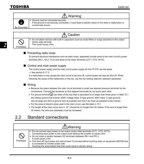
• Ground must be connected securely.<br />
If the ground is not securely connected, it could lead to electric shock or fire when a malfunction or<br />
current leak occurs.<br />
Caution<br />
• Do not attach devices with built-in capacitors (such as noise filters or surge absorber) to the output<br />
(motor side) terminal.<br />
This could cause a fire.<br />
Preventing radio noise<br />
To prevent electrical interference such as radio noise, separately bundle wires to the main circuit's power<br />
terminals (R/L1, S/L2, T/L3) and wires to the motor terminals (U/T1, V/T2, W/T3).<br />
Control and main power supply<br />
The control power supply and the main circuit power supply for the <strong>VF</strong>-<strong>FS1</strong> are the same.<br />
⇒ See section 6.17.3.<br />
If a malfunction or trip causes the main circuit to be shut off, control power will also be shut off. When<br />
checking the cause of the malfunction or the trip, use the trip holding retention selection parameter.<br />
Wiring<br />
• Because the space between the main circuit terminals is small use sleeved pressure terminals for the<br />
connections. Connect the terminals so that adjacent terminals do not touch each other.<br />
• For ground terminal use wires of the size that is equivalent to or larger than those given in table 10.1<br />
and always ground the inverter (200V voltage class: D type ground, 400V class: C type ground).<br />
Use as large and short a ground wire as possible and wire it as close as possible to the inverter.<br />
• For the sizes of electric wires used in the main circuit, see the table in 10.1.<br />
• The length of the main circuit wire in 10.1 should be no longer than 30 meters. If the wire is longer than<br />
30 meters, the wire size (diameter) must be increased.<br />
2.2 Standard connections<br />
Prohibited<br />
Warning<br />
• Do not connect input power to the output (motor side) terminals (U/T1, V/T2, W/T3).<br />
Connecting input power to the output could destroy the inverter or cause a fire.<br />
• Do not insert a resistor between DC terminals (between PA/+ and PC/-).<br />
It could cause a fire.<br />
• First shut off input power and wait at least 10 minutes before touching wires on equipment (MCCB) that<br />
is connected to inverter power side.<br />
Touching the wires before that time could result in electric shock.