- Page 1 and 2:
Industrial Inverter For 3-phase ind
- Page 3 and 4:
I General Operation Disassembly pr
- Page 5 and 6:
4 E6581381 I Warning See item • E
- Page 7 and 8:
I Disposal Mandatory 6 E6581381 Cau
- Page 9 and 10:
⎯⎯ Contents ⎯⎯ I Safety pre
- Page 11 and 12:
iii E6581381 12. Specifications....
- Page 13 and 14:
1 1.2 Contents of the product Expla
- Page 15 and 16:
1 Charge lamp Indicates that high v
- Page 17 and 18:
1 VFFS1-2004 ∼ 2037PM VFFS1-4004
- Page 19 and 20:
1 VFFS1-2220PM -4220, 4300, 4370, 4
- Page 21 and 22:
1 22kW or more: Switch 3) Control c
- Page 23 and 24:
1 A-12 E6581381 1.3.4 How to open t
- Page 25 and 26:
1 Low loads and low inertia loads A
- Page 27 and 28:
1 Power factor correction capacitor
- Page 29 and 30:
1 (2) Affects of leakage current ac
- Page 31 and 32:
1 A-20 E6581381 • Do not install
- Page 33 and 34:
1 Calorific values of the inverter
- Page 35 and 36:
2. Connection Disassembly prohibite
- Page 37 and 38:
2.2.1 Standard connection diagram 1
- Page 39 and 40:
2.3 Description of terminals 2.3.1
- Page 41 and 42:
Terminal symbol Input/output Functi
- Page 43 and 44:
B-9 E6581381 SINK (Negative) logic
- Page 45 and 46:
3. Operations Prohibited Mandatory
- Page 47 and 48:
3.1.1 How to start and stop Exampl
- Page 49 and 50:
(2) Setting the frequency using the
- Page 51 and 52:
Ex.2 (1) Wiring MCCB C-7 E6581381 R
- Page 53 and 54:
4 4.1 Flow of status monitor mode F
- Page 55 and 56:
4 4.2.1 How to set the basic parame
- Page 57 and 58:
4 Example of parameter setting D-6
- Page 59 and 60:
4 D-8 E6581381 [Parameter setting]
- Page 61 and 62: 4 D-10 E6581381 4.2.6 Parameters th
- Page 63 and 64: 5. Basic parameters Before you oper
- Page 65 and 66: E-3 E6581381 [Parameter setting] Ti
- Page 67 and 68: Coast stop (=) E-5 E6581381 Setting
- Page 69 and 70: 5.3 Selection of operation mode Loc
- Page 71 and 72: E-9 E6581381 Title Function Adjust
- Page 73 and 74: Resolution All FM terminals have a
- Page 75 and 76: 5.5 Standard default setting : Def
- Page 77 and 78: 5.6 Forward/reverse run selection (
- Page 79 and 80: E-17 E6581381 [Parameter setting] T
- Page 81 and 82: E-19 E6581381 Warning: When setting
- Page 83 and 84: Motor constant must be set E-21 E65
- Page 85 and 86: Relationship between V/F control mo
- Page 87 and 88: E-25 E6581381 [Parameter setting] T
- Page 89 and 90: [Using a VF motor (motor for use wi
- Page 91 and 92: E-29 E6581381 2) Preset-speed frequ
- Page 93 and 94: 6. Extended parameters Extended par
- Page 95 and 96: Output frequency [Hz] Designated fr
- Page 97 and 98: Output frequency [Hz] + ― Ov
- Page 99 and 100: F-7 E6581381 • Function Use the a
- Page 101 and 102: 3) Sink (Negative) logic / Source (
- Page 103 and 104: F-11 E6581381 (1) A signal is sent
- Page 105 and 106: 6.3.6 Analog VIA / VIB detection :
- Page 107 and 108: 6.4 Basic parameters 2 6.4.1 Switch
- Page 109 and 110: F-17 E6581381 [Parameter setting] T
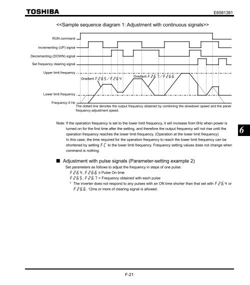
- Page 111: F-19 E6581381 [Parameter setting] T
- Page 115 and 116: 6.5.4 Fine adjustment of frequency
- Page 117 and 118: 6.7 DC braking 6.7.1 DC braking :
- Page 119 and 120: PID command value LL F-27 E6581381
- Page 121 and 122: 6.10 Bumpless operation LOC REM Key
- Page 123 and 124: 100% 90% 80% 70% 60% Reduction of r
- Page 125 and 126: 400V Class for IP20] Output current
- Page 127 and 128: 2) Restarting motor during coasting
- Page 129 and 130: Mandatory 6.12.3 Retry function :
- Page 131 and 132: 6.12.4 Avoiding overvoltage trippin
- Page 133 and 134: F-41 E6581381 [0: Supply voltage un
- Page 135 and 136: F-43 E6581381 The droop control fu
- Page 137 and 138: 2) Types of PID control interfaces
- Page 139 and 140: (D-gain adjustment parameter) F-47
- Page 141 and 142: [Selection 1: Setting vector contro
- Page 143 and 144: F-51 E6581381 : Using this paramete
- Page 145 and 146: 6.16 Acceleration/deceleration time
- Page 147 and 148: F-55 E6581381 Title Function Adjust
- Page 149 and 150: How to set parameters a) Operating
- Page 151 and 152: F-59 E6581381 [Display during opera
- Page 153 and 154: 6.17.5 Output phase failure detecti
- Page 155 and 156: F-63 E6581381 Title Function Adjust
- Page 157 and 158: 1) Output terminal function: 12 (OT
- Page 159 and 160: 6.17.12 Undervoltage trip : Underv
- Page 161 and 162: F-69 E6581381 Output of part repla
- Page 163 and 164:
6.18 Forced fire-speed control func
- Page 165 and 166:
6.20 Operation panel parameter F-73
- Page 167 and 168:
F-75 E6581381 6.20.3 Displaying the
- Page 169 and 170:
An example of setting when is 80 a
- Page 171 and 172:
Example of setting 2 F-79 E6581381
- Page 173 and 174:
F-81 E6581381 [Parameter setting] T
- Page 175 and 176:
The following are available as comm
- Page 177 and 178:
6.21.2 Using the RS485 Setting the
- Page 179 and 180:
6.22 Parameters for options : Para
- Page 181 and 182:
7 (3) Input voltage setting 1 (0 to
- Page 183 and 184:
7 Current signal Voltage signal G-4
- Page 185 and 186:
7 G-6 E6581381 (3) Operation from a
- Page 187 and 188:
8 Note 4 Note 5 Note 5 (Continued)
- Page 189 and 190:
8 Note 10 Note 1 Note 2 Note 3 Note
- Page 191 and 192:
8 Note 3 (Continued) Error code Fai
- Page 193 and 194:
8 Note 6 Note 6 Note 6 Note 6 Note
- Page 195 and 196:
9. Measures to satisfy the standard
- Page 197 and 198:
I-3 E6581381 Three-phase 400V class
- Page 199 and 200:
9.1.4 Measures to satisfy the low-v
- Page 201 and 202:
Voltage class Three-phase 200V clas
- Page 203 and 204:
10 J-2 E6581381 Note 4: For IEC, th
- Page 205 and 206:
10 Magnetic contactor in the secon
- Page 207 and 208:
11. Table of parameters and data 11
- Page 209 and 210:
Title Communication No. Function Un
- Page 211 and 212:
• Frequency parameters Title Comm
- Page 213 and 214:
Title Communicatio n Function Unit
- Page 215 and 216:
Title Communication No. Function Un
- Page 217 and 218:
• Output parameters Title Communi
- Page 219 and 220:
Title Communication No. Function Un
- Page 221 and 222:
Table of input terminal functions 1
- Page 223 and 224:
Table of output terminal functions
- Page 225 and 226:
Table of output terminal functions
- Page 227 and 228:
12 Principal control functions L-2
- Page 229 and 230:
12 12.2 Outside dimensions and mass
- Page 231 and 232:
12 Fig.E Fig.F Fig.G L-6 E6581381
- Page 233 and 234:
13. Before making a service call -
- Page 235 and 236:
M-3 E6581381 Error code (Continued)
- Page 237 and 238:
M-5 E6581381 Note: When the ON/OFF
- Page 239 and 240:
13.4 How to determine the causes of
- Page 241 and 242:
14 Check points 1. Something unusu
- Page 243 and 244:
14 N-4 E6581381 1) Cooling fan The
- Page 245 and 246:
15. Warranty O-1 E6581381 Any part
- Page 247:
TOSHIBA TOSHIBA INDUSTRIAL PRODUCTS