KG68 KG70 KG75 CD500 - Service - Black & Decker
KG68 KG70 KG75 CD500 - Service - Black & Decker
KG68 KG70 KG75 CD500 - Service - Black & Decker

Create successful ePaper yourself
Turn your PDF publications into a flip-book with our unique Google optimized e-Paper software.
10<br />
ENGLISH<br />
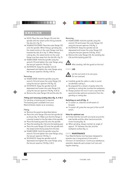
◆ <strong>KG70</strong>: Place the outer flange (12) onto the<br />
spindle with the raised centre facing towards<br />
the disc (A in fig. F).<br />
◆ <strong>KG68</strong>/<strong>KG75</strong>/<strong>CD500</strong>: Place the outer flange (12)<br />
onto the spindle. When fitting a grinding disc,<br />
the raised centre on the outer flange must face<br />
towards the disc (A in fig. F). When fitting a<br />
cutting disc, the raised centre on the outer<br />
flange must face away from the disc (B in fig. F).<br />
◆ <strong>KG68</strong>/<strong>CD500</strong>: Hold the spindle using the<br />
wrench (13) and tighten the outer flange using<br />
the two-pin spanner (14) (fig. G).<br />
◆ <strong>KG70</strong>/<strong>KG75</strong>: Keep the spindle lock (3)<br />
depressed and tighten the outer flange using<br />
the two-pin spanner (14) (fig. A & G).<br />
Removing<br />
◆ <strong>KG68</strong>/<strong>CD500</strong>: Hold the spindle using the<br />
wrench (13) and loosen the outer flange (12)<br />
using the two-pin spanner (14) (fig. G).<br />
◆ <strong>KG70</strong>/<strong>KG75</strong>: Keep the spindle lock (3)<br />
depressed and loosen the outer flange (12)<br />
using the two-pin spanner (14) (fig. A & G).<br />
◆ Remove the outer flange (12) and the disc (5).<br />
Fitting and removing sanding discs (fig. A, H & I)<br />
For sanding, a backing pad is required.<br />
The backing pad is available from your<br />
<strong>Black</strong> & <strong>Decker</strong> dealer as an accessory.<br />
Fitting<br />
◆ Remove the guard as described above.<br />
◆ Place the inner flange (10) onto the spindle (6)<br />
as shown (fig. H). Make sure that the flange is<br />
correctly located on the flat sides of the spindle.<br />
◆ Place the backing pad (15) onto the spindle.<br />
◆ Place the sanding disc (16) onto the backing pad.<br />
◆ Place the outer flange (12) onto the spindle with<br />
the raised centre facing away from the disc.<br />
◆ <strong>KG68</strong>/<strong>CD500</strong>: Hold the spindle using the<br />
wrench (13) and tighten the outer flange using<br />
the two-pin spanner (14) (fig. I).<br />
◆ <strong>KG70</strong>/<strong>KG75</strong>: Keep the spindle lock (3)<br />
depressed and tighten the outer flange using<br />
the two-pin spanner (14) (fig. A & I).<br />
Removing<br />
◆ <strong>KG68</strong>/<strong>CD500</strong>: Hold the spindle using the<br />
wrench (13) and loosen the outer flange (12)<br />
using the two-pin spanner (14) (fig. I).<br />
◆ <strong>KG70</strong>/<strong>KG75</strong>: Keep the spindle lock (3)<br />
depressed and loosen the outer flange (12)<br />
using the two-pin spanner (14) (fig. A & I).<br />
◆ Remove the outer flange (12), the sanding disc<br />
(16) and the backing pad (15).<br />
After sanding, refit the guard on the tool.<br />
USE<br />
Let the tool work at its own pace.<br />
Do not overload.<br />
◆ Carefully guide the cable in order to avoid<br />
accidentally cutting it.<br />
◆ Be prepared for a stream of sparks when the<br />
grinding or cutting disc touches the workpiece.<br />
◆ Always position the tool in such a way that the<br />
guard provides optimum protection from the<br />
grinding or cutting disc.<br />
Switching on and off (fig. J)<br />
◆ To switch on, slide the on/off switch (1)<br />
forward.<br />
◆ To switch off, press the rear part of the on/off<br />
switch.<br />
Hints for optimum use<br />
◆ Firmly hold the tool with one hand around the<br />
side handle and the other hand around the<br />
motor housing (fig. K).<br />
◆ When grinding, always maintain an angle of<br />
approx. 15° between the disc and the<br />
workpiece surface (fig. L).<br />
MAINTENANCE<br />
Your <strong>Black</strong> & <strong>Decker</strong> tool has been designed to<br />
operate over a long period of time with a<br />
minimum of maintenance. Continuous satisfactory<br />
operation depends upon proper tool care and<br />
regular cleaning.<br />
SAG.P65 10<br />
17-07-2001, 14:51